quick troubleshooting guide - tundra international · cm2012 / cm2010 / cm2008 / cm2006 cm2512 /...
TRANSCRIPT

Quick troubleshooting Guide TUN-QTSG-0519-EN_A3 For power inverter models M1500 – M2000 – M2500 – M3000
ANNEX 3
Tel.: 450.649.2470 / 1.877.964.2582 Fax.: 1.888.855.9834 TUNDRAINVERTERS.COM
INSTALLATION WORKBOOK
INSTALLATION WORKBOOK POWER INVERTER SYSTEM / SLEEPER TRUCKS
MODELS: M1500 – M2000 – M2500 – M3000
TUNDRA INTERNATIONAL ALL RIGHTS RESERVED
All rights reserved. No part of this publication may be reproduced or used without the prior written permission of Tundra International. No liability can be accepted for any inaccuracies or omissions in this publication, although every possible care has been taken to make it as complete and accurate as possible. The right is reserved to make changes at any time without prior notice, and without incurring an obligation to make such changes applicable to previously manufactured products. All information contained in this publication is based on the latest product information available at the time of publication. Illustrations and photographs in this publication are intended for reference use only.
© ALL RIGHTS RESERVED APRIL 2017
Part No. TDIW-0417-EN First Edition
PRINTED IN CANADA
1

Quick troubleshooting Guide TUN-QTSG-0519-EN_A3 For power inverter models M1500 – M2000 – M2500 – M3000
ANNEX 3
Tel.: 450.649.2470 / 1.877.964.2582 Fax.: 1.888.855.9834 TUNDRAINVERTERS.COM
TABLE OF CONTENTS
GENERAL INFORMATION FOREWORD 1-1 SAFETY FIRST 1-1 LIMITATIONS 1-2 PRESENTATION 1-2 PARTS LISTING 1-3
INSTALLATION – INSIDE THE CAB DANGER – HIGH VOLTAGE 2-1 THINK QUALITY 2-2 WHERE TO INSTALL THE INVERTER 2-3 VENTILATION 2-4 DETERMINING THE BEST LOCATION 2-5 VALIDATING YOUR LOCATION CHOICE 2-5 FLOOR ADAPTERS – PILOT HOLES 2-6 FLOOR ADAPTERS – HOLE SAW DRILLING 2-7 FLOOR ADAPTERS – INSTALLATION 2-8 POWER INVERTER – INSTALLATION 2-9 / 2-10 CONNECTING THE 12 V CABLES TO THE POWER INVERTER 2-10 / 2-11 GROUNDING VERIFICATION 2-12 GROUNDING PROCEDURE (if required) 2-13 MULTIDATA LCD MONITOR – BEST LOCATION 2-13 MULTIDATA LCD MONITOR – RECESSED INSTALLATION 2-14 / 2-15 MULTIDATA LCD MONITOR – SURFACE INSTALLATION 2-15 / 2-16
INSTALLATION – UNDER THE CAB CABLE PROTECTION 3-1 CABLE ROUTING 3-2 / 3-3 BATTERIES – FUSE HOLDER INSTALLATION 3-4 BATTERIES – CONNECTING CABLES 3-5 BATTERIES – SECURING CABLES 3-6
2

Quick troubleshooting Guide TUN-QTSG-0519-EN_A3 For power inverter models M1500 – M2000 – M2500 – M3000
ANNEX 3
Tel.: 450.649.2470 / 1.877.964.2582 Fax.: 1.888.855.9834 TUNDRAINVERTERS.COM
GENERAL INFORMATION 1-1
FOREWORD This manual is designed to be used primarily by trained mechanics in a properly equipped shop. However, it contains enough information to allow the owner to perform their own basic installation. A basic knowledge of mechanics and electricity, and the proper use of tools and workshop procedures is required in order to adequately and safely perform all tasks. If the owner has insufficient experience or doubts his ability to do the work, installation should only be carried out by a qualified technician. For a successful installation, and to avoid costly mistakes, be sure to read the instructions thoroughly so as to familiarize yourself with the procedures before starting the work. Make sure your work area is clean. Always use the specified tools. Using substitutes may adversely affect the results and the safety of the user. SAFETY FIRST TO REDUCE THE RISK OF ELECTRIC SHOCK, FIRE OR INJURY, PLEASE TAKE NOTE OF THE FOLLOWING RECOMMENDATIONS: 1. A power inverter is an energy conversion device that MUST be taken seriously and that MUST be
installed with care.
2. All steps in this manual should be carefully understood and applied for your own safety and that of others.
3. Do not play with electricity if you do not have the knowledge and the skills required. The electrical
current at the output of this inverter is similar to what the utilities provide and is therefore extremely dangerous if not handled properly. It can cause fire, damage, serious injury, and even death.
3

Quick troubleshooting Guide TUN-QTSG-0519-EN_A3 For power inverter models M1500 – M2000 – M2500 – M3000
ANNEX 3
Tel.: 450.649.2470 / 1.877.964.2582 Fax.: 1.888.855.9834
TUNDRAINVERTERS.COM
GENERAL INFORMATION 1-2
LIMITATIONS Electrical codes may vary depending on the region and type of installation. The electrical installation must comply with local and national standards, and must be carried out by a qualified professional. Tundra International cannot be held liable for incidental or consequential damages or any other damage arising from the use of its products. This includes, without limitation, damage resulting from loss of use, installation or uninstallation costs, and any other problems. Specifications and features for all Tundra International products are subject to change without notice. PRESENTATION The Tundra International truck power inverter system is a battery-powered electrical system providing 120 volts AC power similar to that provided by conventional power grids. When coupled to a battery bank, it produces enough power for the driver to use a variety of electrical and electronic devices. Incorporating the latest technologies, it is one of the most sophisticated and reliable in the industry, and will offer years of trouble-free operation.
Key features - State-of-the-art microprocessor - High-capacity components for a superior service life - Multidata LCD display to track energy consumption and resolve problems - Ultralight one-piece design that withstands strain, vibrations and impacts - Aeronautical-grade assembly Key benefits
- Outstanding efficiency and ultra-precise performance levels at all times - Extends the life cycle of the truck’s electrical charging and starting systems - Lowest cost of ownership – up to 2½ times less than the competition
4

Quick troubleshooting Guide TUN-QTSG-0519-EN_A3 For power inverter models M1500 – M2000 – M2500 – M3000
ANNEX 3
Tel.: 450.649.2470 / 1.877.964.2582 Fax.: 1.888.855.9834
TUNDRAINVERTERS.COM
GENERAL INFORMATION 1-3 PARTS LISTING
Power Inverter
1. Power inverter 2. Multidata LCD monitor 3. Multidata LCD monitor cable 4. Monitor surface mount kit 5. Rubber insulators 6. DC input screws 7. Instruction manual
CM Installation Kit
1. Negative battery cable* 2. Positive battery cable* 3. Positive cable for fuse holder* 4. Plastic ties 5. Floor adapters (strain reliefs) 6. Drilling template 7. Steel clamps 8. Screws for steel clamps 9. Plastic loom 10. Fuse holder 11. Fuse*
* The length and capacity of these parts vary according to each installation kit.
5

Quick troubleshooting Guide TUN-QTSG-0519-EN_A3 For power inverter models M1500 – M2000 – M2500 – M3000
ANNEX 3
Tel.: 450.649.2470 / 1.877.964.2582 Fax.: 1.888.855.9834
TUNDRAINVERTERS.COM
INSTALLATION – INSIDE THE CAB 2-1 DANGER – HIGH VOLTAGE
A power inverter produces an electrical current similar to that produced by conventional power grids. This electrical current has the potential to kill or injure anyone nearby. For safety reasons, a power inverter must always be installed inside the cab, in the luggage compartment under the bed.
6

Quick troubleshooting Guide TUN-QTSG-0519-EN_A3 For power inverter models M1500 – M2000 – M2500 – M3000
ANNEX 3
Tel.: 450.649.2470 / 1.877.964.2582 Fax.: 1.888.855.9834
TUNDRAINVERTERS.COM
INSTALLATION – INSIDE THE CAB 2-2 THINK QUALITY
QUALITY WORK =
RESULTS
7
Quick troubleshooting Guide TUN-QTSG-0519-EN_A3 For power inverter models M1500 – M2000 – M2500 – M3000
ANNEX 3
Tel.: 450.649.2470 / 1.877.964.2582 Fax.: 1.888.855.9834
TUNDRAINVERTERS.COM
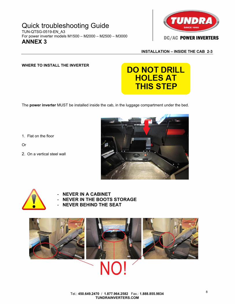
INSTALLATION – INSIDE THE CAB 2-3 WHERE TO INSTALL THE INVERTER The power inverter MUST be installed inside the cab, in the luggage compartment under the bed. 1. Flat on the floor Or 2. On a vertical steel wall
- NEVER IN A CABINET - NEVER IN THE BOOTS STORAGE - NEVER BEHIND THE SEAT
8

Quick troubleshooting Guide TUN-QTSG-0519-EN_A3 For power inverter models M1500 – M2000 – M2500 – M3000
ANNEX 3
Tel.: 450.649.2470 / 1.877.964.2582 Fax.: 1.888.855.9834
TUNDRAINVERTERS.COM
INSTALLATION – INSIDE THE CAB 2-4 VENTILATION 1. Compared to other brands, Tundra International power inverters produce very little heat. A minimum
clearance of 7 cm (2) at the ends is sufficient.
A power inverter should take up as little space as possible to favor the driver. If the power inverter is installed on the floor, make sure it is as close as possible to a wall. A protective plate could be installed over it so that this space can serve as additional storage.
9

Quick troubleshooting Guide TUN-QTSG-0519-EN_A3 For power inverter models M1500 – M2000 – M2500 – M3000
ANNEX 3
Tel.: 450.649.2470 / 1.877.964.2582 Fax.: 1.888.855.9834
TUNDRAINVERTERS.COM
INSTALLATION – INSIDE THE CAB 2-5
DETERMINING THE BEST LOCATION 1. Using the power inverter and the template included in the CM installation kit, determine the best location
to install the power inverter. VALIDATING YOUR LOCATION CHOICE Observe the following 5 criteria 1. The power inverter mounting holes must not damage wires, hoses or other parts under the cab. 2. Floor adapter holes must not damage wires, hoses or other parts under the cab. 3. Do not drill into the cab cross-member. 4. The cables should be kept close to the power inverter, but not too close. They need to be easily installed on
the inverter’s DC inputs. 5. Be aware of the cylinders used to lift the bed. They must not come into contact with the power inverter or its
cables during bed operation.
10

Quick troubleshooting Guide TUN-QTSG-0519-EN_A3 For power inverter models M1500 – M2000 – M2500 – M3000
ANNEX 3
Tel.: 450.649.2470 / 1.877.964.2582 Fax.: 1.888.855.9834
TUNDRAINVERTERS.COM
INSTALLATION – INSIDE THE CAB 2-6
FLOOR ADAPTERS – PILOT HOLES 1. Using the template included in the CM
installation kit, drill two 1/8″ pilot holes to validate your choice of location.
11

Quick troubleshooting Guide TUN-QTSG-0519-EN_A3 For power inverter models M1500 – M2000 – M2500 – M3000
ANNEX 3
Tel.: 450.649.2470 / 1.877.964.2582 Fax.: 1.888.855.9834
TUNDRAINVERTERS.COM
INSTALLATION – INSIDE THE CAB 2-7
FLOOR ADAPTERS – HOLE SAW DRILLING 1. Once the location is confirmed, drill the holes for the floor adapters based on the chart below.
HOLE SAW CHART (hole size depends on CM installation kit to be installed) MODEL CM1512 / CM1510 / CM1508 / CM1506 MODEL CM2012 / CM2010 / CM2008 / CM2006 CM2512 / CM2510 / CM2508 / CM2506 CM3012 / CM3010 / CM3008 / CM3006
Drill the carpet with a hole saw punch that’s the same size as the cables, and then drill the floor from underneath with the required hole saw for your floor adapters. You’ll get a better finish inside the truck.
12

Quick troubleshooting Guide TUN-QTSG-0519-EN_A3 For power inverter models M1500 – M2000 – M2500 – M3000
ANNEX 3
Tel.: 450.649.2470 / 1.877.964.2582 Fax.: 1.888.855.9834
TUNDRAINVERTERS.COM
INSTALLATION – INSIDE THE CAB 2-8
FLOOR ADAPTERS – INSTALLATION 1. Remove the preinstalled nuts. 2. Insert one of the cables through the floor. 3. Lift the carpet and install its nut by hand. 4. Tighten the nut securely with adjustable pliers. (Do not overly tighten.) 5. Repeat steps 1 to 4 for the second cable. 6. Fold the carpet over the cables. The cables should intersect between the floor and the DC inputs of the power inverter. Please note this when inserting cables through the floor. This will allow attaching both cables together and eliminate any possible vibrations of the cables, which could lead to loosening of connections.
1 2 4
13

Quick troubleshooting Guide TUN-QTSG-0519-EN_A3 For power inverter models M1500 – M2000 – M2500 – M3000
ANNEX 3
Tel.: 450.649.2470 / 1.877.964.2582 Fax.: 1.888.855.9834
TUNDRAINVERTERS.COM
INSTALLATION – INSIDE THE CAB 2-9
POWER INVERTER – INSTALLATION 1. Place the power inverter in the designated
location. 2. Using the included bolts, temporarily install the
cables to the DC inputs of the power inverter to validate its position.
Relocate the power inverter if required 3. Using the power inverter as a template, mark the
location of the 4 required mounting holes. 4. Remove the power inverter and drill the 4 holes
of 9/32 inches. 5. Secure the power inverter firmly to the vehicle
using the included bolts and self-locking nuts.
Make sure the power inverter is square with the surrounding surfaces before drilling. Your work will look much better!
CONTINUED ON P. 2-10
2
45 5
3
14

Quick troubleshooting Guide TUN-QTSG-0519-EN_A3 For power inverter models M1500 – M2000 – M2500 – M3000
ANNEX 3
Tel.: 450.649.2470 / 1.877.964.2582 Fax.: 1.888.855.9834
TUNDRAINVERTERS.COM
INSTALLATION – INSIDE THE CAB 2-10
POWER INVERTER – INSTALLATION (cont’d)
Never use self-drilling screws to secure the power inverter to the truck. The thickness of the floor/walls does not provide the required resistance to vibration and to the weight of the power inverter.
Tighten the 4 nuts gradually in crossed sequence at the corners of the power inverter for a uniform clamping force. If mounting on a mat or a rubber surface, do not over-tighten the nuts so as to avoid power inverter distortion.
CONNECTING THE 12 V CABLES TO THE POWER INVERTER 1. Insert the rubber insulators on the cables with the correct
polarity.
RED = POSITIVE BLACK = NEGATIVE
Gently heat the insulators with an electric heat gun; they will be more malleable and easier to insert.
2. Using the included bolts, install the cables to the DC inputs
of the power inverter with the correct polarity. Maximum tightening torque is 20 lb-ft.
1
2
15

Quick troubleshooting Guide TUN-QTSG-0519-EN_A3 For power inverter models M1500 – M2000 – M2500 – M3000
ANNEX 3
Tel.: 450.649.2470 / 1.877.964.2582 Fax.: 1.888.855.9834
TUNDRAINVERTERS.COM
INSTALLATION – INSIDE THE CAB 2-11
CONNECTING THE 12 V CABLES TO THE POWER INVERTER (cont’d) 3. Slide the rubber insulators on each of the cables to
protect the inverter’s DC inputs. 4. Adjust the cables so that they do not create
pressure on the inverter’s DC inputs. 5. Underneath the cab, tighten the floor adapter caps
by hand to secure the cables in place. Do not use pliers as they may damage them.
6. Install the plastic loom over both cable sections.
Use the loom included in the CM installation kit. 7. Using a plastic tie, secure the cables together so
they do not vibrate.
3
5
76
16

Quick troubleshooting Guide TUN-QTSG-0519-EN_A3 For power inverter models M1500 – M2000 – M2500 – M3000
ANNEX 3
Tel.: 450.649.2470 / 1.877.964.2582 Fax.: 1.888.855.9834
TUNDRAINVERTERS.COM
INSTALLATION – INSIDE THE CAB 2-12
GROUNDING VERIFICATION Grounding a mobile power inverter is purely theoretical and has nothing to do with conventional grounding. Grounding a mobile power inverter involves connecting its housing to the vehicle chassis so that the power inverter can more quickly detect any trace of voltage leakage resulting from a damaged 120 V device or extension, or from a positive wire coming into contact with the power inverter or with the vehicle chassis.
If the power inverter is attached to a metal plate in the cabin, its grounding is probably adequate. We recommend checking it by following these steps:
1. Using a test lamp, connect a 12 V power source to the grounding bolt on the back panel of the power inverter. If the lamp comes on, the grounding is adequate.
17

Quick troubleshooting Guide TUN-QTSG-0519-EN_A3 For power inverter models M1500 – M2000 – M2500 – M3000
ANNEX 3
Tel.: 450.649.2470 / 1.877.964.2582 Fax.: 1.888.855.9834
TUNDRAINVERTERS.COM
INSTALLATION – INSIDE THE CAB 2-13
GROUNDING PROCEDURE (if required) 1. Using a 12 V test lamp, find the “grounding” point closest to the power inverter. A metallic part connected to
the vehicle chassis is ideal.
2. Using an 8 AMG wire with terminals, connect the
GROUND terminal on the back panel of the power inverter to your grounding point of contact with the chassis.
3. Confirm your installation with a 12 V test lamp using the GROUNDING VERIFICATION procedure on page
2-12.
Do not connect the GROUND terminal to the negative input terminal of the power inverter.
MULTIDATA LCD MONITOR – BEST LOCATION Determine the best location to install the multidata LCD monitor according to the following 3 criteria: 1. The inverter’s location must allow the driver to
visualize it during operation.
2. The monitor cable measures 20 ft. (6 m). It must not be lengthened or doubled.
3. The multidata LCD monitor can be installed
flush or surface mounted.
18
Quick troubleshooting Guide TUN-QTSG-0519-EN_A3 For power inverter models M1500 – M2000 – M2500 – M3000
ANNEX 3
Tel.: 450.649.2470 / 1.877.964.2582 Fax.: 1.888.855.9834
TUNDRAINVERTERS.COM
INSTALLATION – INSIDE THE CAB 2-14
MULTIDATA LCD MONITOR
RECESSED INSTALLATION p. 2-14 SURFACE INSTALLATION p. 2-15
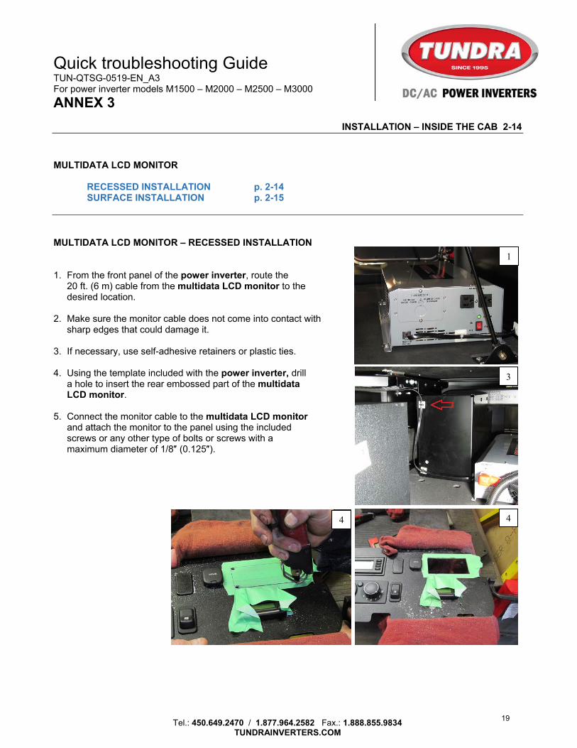
MULTIDATA LCD MONITOR – RECESSED INSTALLATION 1. From the front panel of the power inverter, route the
20 ft. (6 m) cable from the multidata LCD monitor to the desired location.
2. Make sure the monitor cable does not come into contact with
sharp edges that could damage it. 3. If necessary, use self-adhesive retainers or plastic ties. 4. Using the template included with the power inverter, drill
a hole to insert the rear embossed part of the multidata LCD monitor.
5. Connect the monitor cable to the multidata LCD monitor
and attach the monitor to the panel using the included screws or any other type of bolts or screws with a maximum diameter of 1/8″ (0.125″).
1
3
44
19

Quick troubleshooting Guide TUN-QTSG-0519-EN_A3 For power inverter models M1500 – M2000 – M2500 – M3000
ANNEX 3
Tel.: 450.649.2470 / 1.877.964.2582 Fax.: 1.888.855.9834
TUNDRAINVERTERS.COM
INSTALLATION – INSIDE THE CAB 2-15
MULTIDATA LCD MONITOR – RECESSED INSTALLATION (cont’d)
We suggest validating your cutting measurements more than once so as to minimize the chances of damaging the panel. Moreover, we suggest using masking tape to avoid scratches during cutting.
MULTIDATA LCD MONITOR – SURFACE INSTALLATION
1. From the front panel of the power inverter, route the 20 ft. (6 m) cable from the multidata LCD monitor to the desired location.
2. Make sure the monitor cable does not come into
contact with sharp edges that could damage it.
5
1
20

Quick troubleshooting Guide TUN-QTSG-0519-EN_A3 For power inverter models M1500 – M2000 – M2500 – M3000
ANNEX 3
Tel.: 450.649.2470 / 1.877.964.2582 Fax.: 1.888.855.9834
TUNDRAINVERTERS.COM
INSTALLATION – INSIDE THE CAB 2-16
MULTIDATA LCD MONITOR – SURFACE INSTALLATION (con’d)
3. Release the two parts of the monitor
surface mount kit (included).
4. Insert the cable into the opening of the bottom cover (part 1) and secure the cover to the desired surface.
5. Attach Part 2 to Part 1 by pressing firmly.
6. Connect the cable to the multidata LCD
monitor.
7. Install the multidata LCD monitor with the included screws.
4
75
3
21

Quick troubleshooting Guide TUN-QTSG-0519-EN_A3 For power inverter models M1500 – M2000 – M2500 – M3000
ANNEX 3
Tel.: 450.649.2470 / 1.877.964.2582 Fax.: 1.888.855.9834
TUNDRAINVERTERS.COM
INSTALLATION – UNDER THE CAB 3-1
CABLE PROTECTION 1. Before attaching the cables under the
cab, cover them with the plastic loom included in the CM installation kit (from one end to the other). This will help protect them from road debris and allow them to maintain their integrity much longer.
2. Every 12, attach the battery cables
together using the included plastic ties (from one end to the other). This will help to protect them.
DC cables can produce magnetic fields strong enough to interfere with radio communication devices. Tying them together will fuse the positive and negative fields and eliminate most negative effects.
1
2
22

Quick troubleshooting Guide TUN-QTSG-0519-EN_A3 For power inverter models M1500 – M2000 – M2500 – M3000
ANNEX 3
Tel.: 450.649.2470 / 1.877.964.2582 Fax.: 1.888.855.9834
TUNDRAINVERTERS.COM
INSTALLATION – UNDER THE CAB 3-2
CABLE ROUTING
Routing the cables to the battery box is an important step.
1. Never suspend the power inverter cables to the truck’s cables or hoses.
2. Beware of exhaust pipes. Their heat could damage the cables.
3. Pay attention to metal parts with sharp edges; they could damage the cables. 1. Route the power inverter cables to the battery
box. Fasten them securely to the chassis of the cab using the metallic clips and self-drilling screws included in the CM installation kit.
23
Quick troubleshooting Guide TUN-QTSG-0519-EN_A3 For power inverter models M1500 – M2000 – M2500 – M3000
ANNEX 3
Tel.: 450.649.2470 / 1.877.964.2582 Fax.: 1.888.855.9834
TUNDRAINVERTERS.COM
INSTALLATION – UNDER THE CAB 3-3
CABLE ROUTING (cont’d)
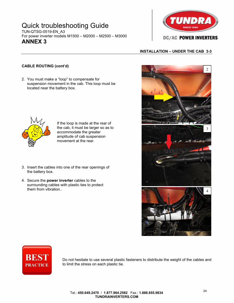
2. You must make a “loop” to compensate for suspension movement in the cab. This loop must be located near the battery box.
If the loop is made at the rear of the cab, it must be larger so as to accommodate the greater amplitude of cab suspension movement at the rear.
3. Insert the cables into one of the rear openings of the battery box.
4. Secure the power inverter cables to the
surrounding cables with plastic ties to protect them from vibration..
Do not hesitate to use several plastic fasteners to distribute the weight of the cables and to limit the stress on each plastic tie.
2
3
4
24

Quick troubleshooting Guide TUN-QTSG-0519-EN_A3 For power inverter models M1500 – M2000 – M2500 – M3000
ANNEX 3
Tel.: 450.649.2470 / 1.877.964.2582 Fax.: 1.888.855.9834
TUNDRAINVERTERS.COM
INSTALLATION – UNDER THE CAB 3-4
BATTERIES – FUSE HOLDER INSTALLATION 1. Detach the cover from the base of the fuse holder
by pressing firmly on both sides simultaneously, while lifting the cover to separate the two parts.
2. Remove the nuts and washers. 3. Install the fuse included in the CM installation
kit in accordance with the upper leg’s direction of rotation.
4. On one of the terminals, install the positive cable
(red) from the power inverter, overlap the washer and nut, and tighten the nut to 10 lb-ft.
5. On the other terminal, install the 12 positive
cable (red) included in the CM installation kit, overlap the washer and nut, and tighten the nut to 10 lb-ft.
6. Install the protective cover by pressing firmly.
Never apply a greasy “protective” product on battery posts. This will attract contaminants, interfere with the quality of the connections, and discharge the batteries. If necessary, use a liquid protective product that dries completely.
1
3
6
25

Quick troubleshooting Guide TUN-QTSG-0519-EN_A3 For power inverter models M1500 – M2000 – M2500 – M3000
ANNEX 3
Tel.: 450.649.2470 / 1.877.964.2582 Fax.: 1.888.855.9834
TUNDRAINVERTERS.COM
INSTALLATION – UNDER THE CAB 3-5
BATTERIES – CONNECTING CABLES
Before connecting the cables to the batteries, make sure that the switch on the front panel of the power inverter is OFF. If the vehicle is equipped with Dynacraft battery interconnectors, we suggest following the procedure in the Technical Bulletin section to maximize connectivity and ensure proper operation of the power inverter. Ignoring our instructions may result in the inverter not operating at full power.
1. The power inverter cables must be connected to
the batteries in order to distribute the charge evenly between the four batteries. A. The positive and negative cables must be as
far apart as possible from one another. B. Maximum of three terminals per battery post. C. The power inverter cables must be placed
above the interconnectors and not underneath.
D. Do not install other accessories where there is a power inverter cable.
2. Connexion of the cables must be made in the
following order: 1. Positive – 2. Negative
A spark may occur when connecting the negative cable. This is normal if the power inverter capacitors are not charged.
1
2
26

Quick troubleshooting Guide TUN-QTSG-0519-EN_A3 For power inverter models M1500 – M2000 – M2500 – M3000
ANNEX 3
Tel.: 450.649.2470 / 1.877.964.2582 Fax.: 1.888.855.9834
TUNDRAINVERTERS.COM
INSTALLATION – UNDER THE CAB 3-6
BATTERIES – SECURING CABLES To insure your safety:
1. The power inverter cables must be attached with plastic ties to the other cables on the top of the batteries.
2. If there is excess cable, do not cut it. It must be wound on the top of the batteries and also attached to the other cables.
It is preferable to never attach the fuse holder to a battery box wall. The safest location is on top of the batteries.
1
2
27