quickstart manual - speedway motors...1 550-849, 550-850, & 550-851 quickstart manual sniper efi...
TRANSCRIPT

1
550-849, 550-850, & 550-851
QUICKSTART MANUAL SNIPER EFI INSTALLATION INSTRUCTIONS
Congratulations on your purchase of a new Sniper EFI Throttle Body System built by craftsmen to exacting standards in our Bowling Green, Kentucky facility. Every Sniper EFI System is tested for functionality before it leaves our facility for “bolt on and go” performance.
Should you experience any problems or need parts assistance that this quickstart manual or the complete installation manual does not address, please feel free to contact our technical service department at 1-866-464-6553 Monday through Friday, 8 a.m. to 5 p.m. CST or log on to www.holley.com for a database of technical information and online support. For a full instruction manual please visit Holley.com and download the complete Instruction Manual. Link Address: http://documents.holley.com/199r11321.pdf
2
INTRODUCTION & SYSTEM REQUIREMENTS Holley Performance Products has written this manual for the installation of the Sniper EFI TBI fuel injection system. This basic manual contains the information necessary for the installation of the throttle body, wiring, and sensors. Please read all the WARNINGS and NOTES, as they contain valuable information that can save you time and money. It is our intent to provide the
best possible products for our customer; products that perform properly and satisfy your expectations.
Engine Requirements Before moving forward with the installation, please verify your vehicle meets the engine and fuel system requirements below:
Engine is in good running health
Engine is a naturally aspirated (no supercharger, turbo charger, etc.) 4, 6 or 8 cylinder
Engine has a 2 BBL, 2300 style flange intake manifold
Unleaded fuel only
Any RTV silicone sealants used on the engine are sensor safe
Fuel System Requirements The Sniper EFI system requires a high pressure fuel pump capable of operating at 60 psi. When selecting a pump and lines, be sure each component is designed to perform at high pressure. Holley offers a variety of fuel pumps, hoses and accessories to complete your installation. For best results, Holley strongly recommends an in-tank pump. Installing the fuel pump in the tank results in quieter operation, less chance of cavitation and a reduction in pump temperature. If mounting the pump in the tank is not an option, install the pump as close as possible to the tank, within 2-feet of sending unit is recommended. Once the fuel system is installed, checking the fuel pressure on the inlet side of the Sniper EFI is recommended. The 550-849K, 550-850K & 550-851K fuel injection systems include the complete fuel system. The fuel system parts
identification and instructions can be found in the Sniper EFI Reference Manual.
TOOLS REQUIRED FOR INSTALLATION
Standard Wrench Set Small Blade Screwdriver Allen Wrench Set
Medium Blade Screwdriver #2 Phillips Screwdriver Digital Voltmeter
Drill and Assorted Bit Sizes Terminal Crimping Tool
Factory Service Manual for your vehicle 7/8” Drill Bit (step-bit recommended)
An assistant is necessary for some installation and adjustment procedures and should be present for safety reasons. WARNING! Disconnect battery before proceeding with any Fuel Injection installation.
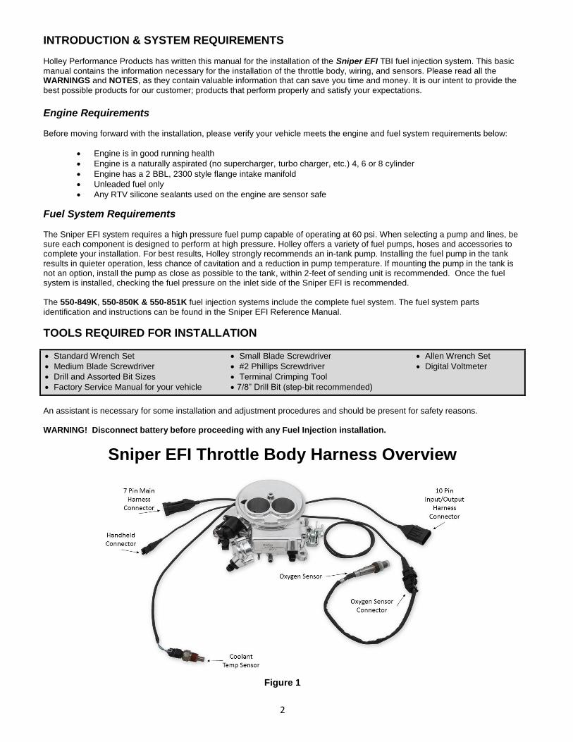
Sniper EFI Throttle Body Harness Overview
Figure 1

3
Before you get started – Are you experiencing any underlying problems?
Holley Performance highly recommends the following items be checked and/or corrected prior to installation of your
new Sniper EFI system to ensure optimum performance from your engine.
Many times a carburetor is looked at as the prime culprit or the main cause for a myriad of other engine-related difficulties that
might exist. Therefore, it’s best to check and verify the condition of the complete engine system before proceeding with an EFI
conversion. There should be no vacuum leaks, the ignition timing should be properly set, and the engine should be in
sound mechanical condition. Converting to EFI won’t cure bad valves, damaged head gaskets, worn piston rings, or
cracked and leaking vacuum lines.
Spark plug wires cannot be of Solid Core Construction – It is recommend to use MSD 8.5 Super Conductor Wires with the Sniper EFI
INSTALLATION:
NOTE: Please see the enclosed instruction manual for complete removal, installation, and tuning instructions.
NOTE: This Quickstart Manual covers NON-Timing Control Ignition Options. We highly recommend first starting the engine
with one of the two NON-Timing Control Ignition types shown in step 8 for your first start-up!
Before beginning the Sniper EFI installation, we recommend that you locate a CLEAN Switched
12v Ignition source. This source needs to have 12v while cranking, and with the key in the run
position. Label this source now, as you will need to use it for Step 9. Do NOT connect the
switched 12v wire to a source such as the ignition coil, or starter solenoid.
WARNING – Disconnect the NEGATIVE battery cable before any work is performed to the vehicle. 1. Start by labeling all vacuum lines for easy identification, i.e. brake booster & vac advance for distributor. If any lines appear
damaged, now is the time to replace them. Next, remove the carburetor, clean the gasket mating surface, and install the provided intake flange gasket on the intake manifold.
2. Place the Sniper EFI throttle body on top of the new flange gasket on the manifold. Install the hold down nuts and snug down progressively in a “criss-cross” pattern (60-80 in.lbs.). Depending on your application, this is also the time to install your throttle bracket and transmission kickdown brackets provided with your Sniper EFI Kit. You may be able to re-use the stock style throttle stud or transmission studs from your carburetor. If not, we have provided several universal throttle ball/stud options.
Throttle Linkage/Bracket Side View
Figure 2
3. Reconnect the throttle and transmission kick-down linkage. Be sure to check for any binding conditions and correct before proceeding. Poorly routed throttle cables & linkages can cause throttle pedal issues. See figure 2 for correct linkage placement.
4. Install the Coolant Temperature Sensor into a 3/8” NPT coolant passage in either the intake manifold or cylinder head.
Do not overtighten or damage to the cylinder head or intake may occur. It is best to drain some of the coolant before the sensor is installed. Use thread sealer or a small amount of thread tape. Do not install the sensor in the thermostat housing, or in an area that will not see a constant flow of coolant.
Throttle Stud/Ball
TH350 Kick Down
200-4R / 700-R4 Kick Down
Ford C4 / C6 Kick Down

4
5. Reconnect the appropriate vacuum hoses to the Sniper EFI throttle body. Be sure to plug any vacuum sources not used
on both the Sniper EFI Throttle Body and on the Engine. See Figure 3 for diagram of vacuum ports.
Vacuum Port Side View
Figure 3
6. Connect fuel feed and return hose. It is mandatory that the fuel outlet/return comes from the fuel pressure regulator and the
fuel inlet must go to the inlet fitting on the 2300 Sniper EFI. The inlet and outlet are indicated in Fuel Fitting Overview
below. The Sniper EFI System comes with a built in fuel pressure regulator, factory set at 58.5psi. We recommend at least a 3/8” feed line and 3/8” return line.
Note: Fuel pressure should be checked on the inlet fuel line before initial start up during the fuel pump prime.
We recommend Earl’s Part Number 100187ERL (0-100 psi Liquid filled gauge) & AT100199ERL (-6AN Gauge Adapter) to check fuel pressure.
Fuel Fitting Overviews
Figure 4
Locate a position for the oxygen sensor as close to the engine as possible. The oxygen sensor should be mounted at a point where it can read a good average of all the cylinders on one bank. This would be slightly after all the cylinders merge. If you have long tube headers, mount the sensor approximately 1-10” after the collector. You must have at least 18” of exhaust pipe

5
after the sensor. Verify that the Oxygen sensor is tight in the bung, if the gasket is not seated properly on the O2 sensor exhaust leaks and poor engine operation will occur.
7. If your vehicle has catalytic converters, the oxygen sensor MUST be located between the engine and the catalytic
converters. It is also CRITICAL that the oxygen sensor is NOT installed in the bottom of the exhaust tube. This will help prevent condensation in the exhaust tubing from entering the sensor. The clamp-on kit installation requires a 3/4 hole to be drilled in the exhaust system. Refer to main installation manual for more details.
a. Note: Verify that the O2 cable is supported correctly and away from heat sources such as the exhaust. If the
O2 cable has melted, this is not fixed under warranty and will require the unit to be sent back to Holley to be repaired at customer cost.
Oxygen Sensor Bung Clamp-On Oxygen Sensor Bung
WARNING! Only use ONE of the following Ignition Installation Options. Coil negative is intended for the stock ignition systems. CD Box Ignition is intended for users that have an aftermarket ignition system but do not want the ECU to control timing. A Magnetic Distributor such as an MSD distributor or a Holley Dual Sync Distributor is needed to have the Sniper EFI control the ignition timing. NEVER connect the Purple wire to the Ignition Coil!

6
8. Option 1. Coil (-) Ignition - Locate the YELLOW wire on the Main 7 Pin Harness, this wire will be labeled Coil (-) Input.
This wire can either go to the NEGATIVE side of your ignition coil, or to “Tach” label on a GM Large Cap HEI distributor w/
internal coil. NEVER run the YELLOW wire to the negative side of a coil while using a CD Ignition box.
Coil (-)
OR
9. Option 2. Capacitive Discharge Ignition – “CD Box” - Locate the small 1 purple wire ignition adapter. It has a single
PURPLE wire attached to a 2 pin connector (Shown in Figure 11). Connect this wire to the distributor connector on the main harness. The PURPLE wires should plug into each other – the GREEN wire will be unused. The loose end of the PURPLE wire will then be terminated to the tach output wire on the C/D Box. On an MSD 6AL (shown below) this wire is GREY. Refer to the ignition box instructions for more information on the tach output wiring. If using this step, NEVER connect the PURPLE wire to the ignition coil!
Note: If ignition box or distributor has ability to send rpm signals with initial key on (such as a Tach Sweep or Rev Limiter Verification), these settings must be disabled. Reference ignition system instructions.

7
CD Box
CAUTION! NEVER connect any of the EFI wires to the coil on any CD type ignition system. The ECU will
be permanently damaged!
10. The PINK wire labeled “Switched Ignition” needs to be terminated to the ignition source found at the beginning of this
manual. We STRONGLY recommend that you do not stack this wire with other switched 12v accessories. This wire needs
to be isolated on its own individual switched 12v power source. Failure to do this may result in a “no start” condition. 11. Connect the 3.5” Sniper EFI Handheld to the main harness. This is a simple plug and play connection. If you are going to
permanently leave the handheld in the vehicle, you will need to find a factory grommet in your firewall to pass the Display CAN bus connector through and secure the excess wire away from hazards. If no factory grommets can be utilized we recommend installing one.
Sniper EFI Touchscreen LCD Display
Note: If the Touch Screen LCD Display needs to be unhooked
from the Sniper EFI. Depress the lock tab on the male side of the
connector as show in the following pictures.

8
12. At this point you are ready to install the battery power and ground cables. The wires must go DIRECTLY to the physical
battery terminals. The battery must be fully charged before attempting to start the Sniper EFI. Do not attempt to start the
engine with the Sniper EFI hooked to a battery charger.
Battery connections MUST physically go the battery!
ADDITIONAL INPUTS AND OUTPUTS
The following tables outline the functions of each wire on the Sniper harnesses. For detailed information, please see referenced sections of the Sniper EFI Reference Manual included with your kit.
7 Pin Connector Pin Color Labeled Name Function E Red Battery Positive (+) Connects directly to battery positive terminal G Black Battery Negative (-) Connects directly to battery negative terminal C Blue Fuel Pump Output (+) +12v Fuel Pump Supply from Relay A Violet Crank Signal Positive (+) Engine Speed Signal Input (see Ignition Wring Section) B Dark Green Crank Signal Negative (-) Engine Speed Signal Ground (see Ignition Wiring section) D Yellow Coil (-) Input Engine Speed Input (see Ignition Wiring section) F Pink Switched Ignition (+12v) NOTE: must remain powered during cranking
10 Pin Connector – 8 wires are populated. This connector contains: Pin Color Labeled Name Function A Orange Input #1 (-) Optional - Connect to a ground triggered A/C relay B Yellow Input #2 (-) Optional - Connect to a programmable ground input C Light Blue Output #1 (-) Optional – Connect to Fan #1 relay ground trigger D Light Green Output #2 (-) Optional – Connect to Fan #2 relay ground trigger E Grey Output #6 (-) Optional – Connect to ground side trigger of A/C shutdown relay F White Points Output Used to trigger a CD ignition box or the included Coil Driver Module G Dark Brown Tach Output Used to drive an aftermarket tachometer H Tan Digital Gauge Output Used to drive Holley EFI analog gauges via 554-130 Gauge Module
NOTE: To have Sniper EFI control any cooling fans or AC kick, please refer to the Instruction Manual. The ground
outputs from the Sniper EFI are rated for 2 Amps and less, they can only be used to trigger a relay on the ground side.
INITIAL POWER-UP AND WIZARD
Turn the ignition key to the “run” position. If wired properly the Sniper EFI will power the Sniper EFI Touch Screen LCD. The Home Screen (figure below) should appear.
The Sniper EFI Home screen contains icons which will navigate to different functional features of the Touch Screen. These features will be discussed in detail throughout the main manual.

9
It is now time to begin the Calibration Wizard!
NOTE: DO NOT ATTEMPT TO START THE VEHICLE UNTIL YOU ARE TOLD TO DO SO IN THE INSTRUCTIONS BELOW. NOTE: The handheld has an SD memory card installed in the side. This card contains specific information that is required for
the use of the Sniper EFI product. DO NOT replace this card with another. There should be no need to remove this card for normal use.
STEP 1
Select WIZARD from the main menu
STEP 2
- Select your Sniper system type
- Press Next
STEP 3
- Select the number of cylinders your engine has
- Press Next
STEP 4
- Use the slider bar to input the displacement of
your engine
- Press Next
STEP 5
- Use the slider bar to set your desired HOT idle
speed. This is the RPM the Sniper will target at
coolant temperatures above 160 °F
- Press Next

10
STEP 6
- Select your camshaft type:
Stock/Mild = This selection will work well on most applications equipped with stock or “street performance” camshafts. Choose Stock/Mild if you are unsure of your camshaft specs
- Press Next
STEP 7
-Select your ignition type, Non Timing Controlled Methods covered by this Quick Start Guide are:
Coil (-) [no timing control]
CD Ignition Box [no timing control]
- Press Next
STEP 8
After answering all questions in the Wizard, your calibration will be created. Press the “Start” button to send the calibration to the ECU. Once this process is completed, you will see a screen indicating the file has been uploaded. Once file is uploaded, the Ignition Needs to be cycled.
SENSOR VERIFICATION
Before starting the vehicle, verify that all of the sensors are reading properly. To do this, turn the key off, and cycle it back on. You should hear the fuel pump come on and run for 5 seconds.
Note: This is a great time to check for fuel leaks and verify fuel pressure.
On the HOME SCREEN, select the MONITOR icon, then select the “Monitors” screen. You will see an icon named “Initial Startup”. Select this. With the key on and the engine off, these sensors should read as follows:
Engine RPM – This gauge should show “Stall!”, once you begin cranking the engine it will show actual engine RPM
TPS (Throttle Position Sensor) – Should read 0. Slowly depress the throttle to wide open. It should read between 85
and 100% at wide open throttle. If it does not, please verify your throttle linkage is allowing full travel of the throttle arm.
MAP (Manifold Air Pressure Sensor) – Should read from 95-102. At high elevations it could read as low as 75.
CTS (Coolant Temperature Sensor) – reads engine temperature.
IAC Position – See Idle Setting/Throttle Plate Setting section in this manual.
Battery – Will read battery voltage. Should be 12.0 volts minimum.
Fuel Prime occurs 2.5 seconds after key-on (which is also the amount of time it takes for the touch screen to load). If you quickly turn the ignition key without waiting for the full 2.5
seconds, the prime will not occur and it may take longer for the engine to start.
Caution! Multiple key cycles without firing the engine could potentially cause a flooded condition. If ignition box or distributor has ability to send rpm signals with initial key on (such as Tach Sweep or Rev
Limiter Verification), these settings must be disabled. Reference ignition system instructions.

11
Initial Startup Screen
If ANY of these sensors are not reading properly, the underlying issue must be resolved before the engine is started.
PRE-STARTUP CHECKLIST
Before starting the engine, double check for leaks, proper wire routing, any wiring hazards or loose nuts and bolts. This is a great time to visually inspect the overall Sniper EFI install.
- Verify Wiring - ECU must be powered and grounded directly at the battery and the battery is fully charged. o Pink Wire must be attached to a 12V+ switched source that has voltage during cranking and run positions
of the ignition switch. Verify this source with a multimeter. o Coil Negative Ignition setups must have the Yellow Wire (coil – input) on the negative terminal of the
Ignition Coil o CD Box Ignition (no timing control) setups must have the Tach Output Wire from CD box connected to the
purple wire (Crank Signal Positive) in the Sniper EFI Harness, using the provided Tach Signal Adapter. - Handheld powers up - Wizard has been run with correct Non Timing Controlled Ignition setup chosen - Fuel pressure has been verified at the Sniper EFI throttle body and is between 55 & 65 psi - All wiring has been tied away from potential hazards such as the exhaust, fans, pulleys, spark plug wires, 12 Volt
accessory wires, the ignition coil and ignition coil wiring. o Pay specific attention to the O2 sensor cable lead. Make sure that it is tied out of the way from any heat
sources or other hazards.
STARTUP With the handheld still on the “Initial Startup” screen, crank the engine and look at the RPM parameter. It should change to “Syncng”, indicating the ECU is syncing with the RPM signal for an instant, then show an RPM signal. The engine should fire and run and come to an idle. If the engine does not start please use the flow chart in the Sniper EFI Troubleshooting Guide on www.holley.com. If the issue still continues, call Holley Tech service for advice. If the engine starts but is idling too low and appears to be struggling for air, you may have to open the throttle body idle speed screw at this time. A loud whistling may be experienced at idle if the throttle blades need be opened further. Refer to the section called “Idle Setting/Throttle Plate Setting” on page 12. AFTER STARTUP Once the vehicle has started, double check for any fuel or coolant leaks. Let the vehicle warm up and look at some other parameters to make sure everything is operating properly. Go into the MONITOR, MULTI GAUGE, and select the “AIR/FUEL RATIO” Icon.
AFR, A/F – This will show the air/fuel ratio the wideband oxygen sensor is reading. The Closed Loop Compensation
should be adding or subtracting fuel all the time such that the AFR should always be close to the Target AFR value.
Target Air/Fuel Ratio – This is the target AFR (air/fuel ratio) the ECU is trying to maintain. This will vary depending on
the engine speed and load and coolant temperature.
Coolant Enr, %: Indicates the amount of enrichment based on the coolant temperature. 100% is zero enrichment and
will not reach this point until the engine is 160 Degree F. Engine will not go into learn mode until this is at 100%.
CL Status – Indicates whether the engine is “Closed Loop” or “Open Loop”. Closed Loop indicates that the ECU is
adding or subtracting fuel to maintain the target air/fuel ratio. The Sniper EFI calibrations are such that the system should be operating closed loop almost all of the time.
CL Comp, % – This is the percentage of fuel that the ECU is adding or subtracting to maintain the target air/fuel ratio
at any specific moment. A value with a minus (-) sign in front indicates the ECU is removing fuel. A value with no minus sign indicates the ECU is adding fuel. When in open loop operation, this will always stay at 0%.

12
Learn Status – This indicates the status of the Sniper EFI “Self Tuning” operation (Learn Status). The system will
automatically tune itself as you drive around. There are several conditions that must occur in order for the Self Tuning to occur. The engine temperature must exceed 160° F. The system must be operating in a closed loop mode, and the Self Tuning must be enabled. The base Sniper EFI setups have the Self Tuning enabled. Once the engine reaches 160° F, the Self Tuning should be active. The Learn Stat will show “NoLearn” when Self Tuning is not active and “Learn” if Self-tuning is active.
Current Learn, % - This is the percentage of fuel the ECU is adding or subtracting to the base fuel map. This is not a
progress bar. A value with a minus (-) sign in front indicates the ECU is removing fuel from the base fuel map. A value with no minus sign indicates the ECU is adding fuel to the base fuel map. Typical readings are between -20% - 20%, but can be higher or lower depending on the application that the Sniper EFI is installed on.
Inj PW, msec – Indicates the injector pulsewidth. This will vary depending on the engine speed and load.
RPM, rpm – Indicates the frequency that the engine is running at.
Fuel Flow, lb/hr – Indicates the amount of fuel being injected into the engine at any given time. This will vary
depending on the engine speed and load.
AIR/FUEL RATIO Multi-Gauge AIR/FUEL RATIO Multi-Gauge Engine below 160° F (NoLearn) Engine above 160° F (Learng)
If any of these parameters are not showing a proper value, find out why before further driving the vehicle.
IDLE SETTING/THROTTLE PLATE SETTING Once the engine is up to operating temperature (above 160° F), the idle speed can be set to what was configured in the Wizard. To do this, open up the Initial Startup gauge screen. With the vehicle in neutral, adjust the idle screw until the IAC Position reads between 2% and 10%. While adjusting the throttle plate screw, watch the TPS value and make sure it stays at 0%. While adjusting the throttle plate screw, the TPS position may begin to read higher than 0%. If this happens cycling the ignition switch will recalibrate the TPS back to zero. NOTE: Do not attempt to set the target idle speed and IAC position until the engine is above 160°F!

13
FIRST DRIVE Congratulations on a successful installation of your Sniper EFI system! Next, you need to simply drive your car and let the Sniper’s self-tuning occur. It is best to drive in an area without much traffic where you can drive under different conditions. It’s always a good idea to have a passenger present to look at things like coolant temperatures, battery voltage, etc, on the first drive. Start the car and let it idle. Let the car get up to operating temperature (coolant temperature over 160 degrees F) so that the self-tuning can occur. If you’d like, have a passenger look at the handheld display and look at the “Cl Comp” value. Once this value is close to zero, the self-tuning process has been completed in that engine operating area. Next, put the car into gear if it’s an automatic and let it run there. If the vehicle has air conditioning, you can turn it on, which will put the engine in a different tuning area as well. Next, slowly accelerate from a stop. If the transmission is a manual, do some slow clutch engagements away from a stop. Then cruise the vehicle at a steady speed, varying the speeds after a few minutes of steady driving. You can also drive in different gears. What you are trying to do is run the vehicle at different engine speed and loads. After driving under various driving conditions, you can perform some harder acceleration runs including WOT runs. After this, the Sniper EFI will have performed most of the self-tuning required for a good running engine. As closed loop percentage trends towards 0% in all driving conditions, the Sniper EFI has learned enough to transfer the learn table to the base fuel table and lower the Learn Comp Limits. Reference the Sniper EFI instructions for further details on transferring the learn table and lowering the Learn Comp Limits. Just performing routine driving will accomplish the learning process. After the engine is up and running and has some drive time on it minor tuning refinements can be performed to optimize fuel economy and power by the user.
14
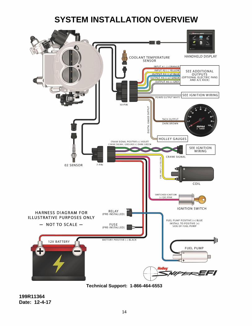
SYSTEM INSTALLATION OVERVIEW
Technical Support: 1-866-464-6553
199R11364 Date: 12-4-17