quickvision - subsea uk mckie... · 5 quickvision toolset level line draws a leveled plane/horizon...
TRANSCRIPT

QuickvisionMeasurement and Positioning by Augmented Reality

www.fugro.com2
Introduction
Technology
Application
Benefits
Track Record
www.fugro.com3
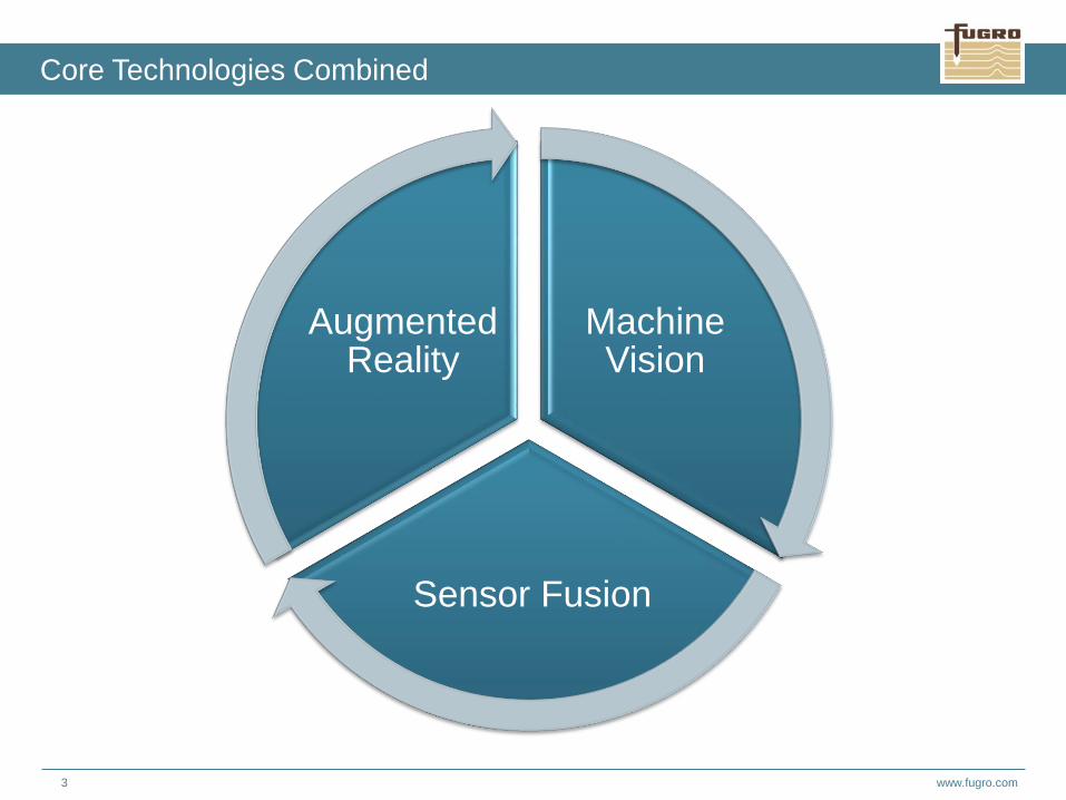
Core Technologies Combined
Machine Vision
Sensor Fusion
Augmented Reality

www.fugro.com4
Quickvision Hardware Details
(Standard) Hardware Features:
▪ Framerate: 10Hz
▪ Angle of View: 71 x 61degrees
▪ Field of View : Work. Dist. vs FoV ~ 1:1.4; 1:1.1
▪ Resolution: 2456 x 2054 pixels
▪ Sensor Type: Colour
▪ Lens: Fixed Focus / Fixed Aperture / Pre-calibrated
▪ Fixed Pose
▪ Spherical Sapphire Glass Viewport
▪ Mass in air: 4.1kg
▪ Mass in water: 2.1kg
▪ Supply voltage: 8 - 30VDC @ < 4.5W
Depth Rating: 6000m
Embedded MEMS IMU
Interface and I/O
Streaming: Gigabit Ethernet, support for 100Mbit
Camera triggering : RS232
IMU data transfer: RS422/232

www.fugro.com5
Quickvision Toolset
level line
Draws a leveled plane/horizon on the
image from which the height of an object
can be inferred.
Inclinometer
Measures the attitude/inclination of an object. The
protractor is drawn interactively on the screen on a
paused image The tool will automatically find and snap
to an edge.
Compass Rose
Augments the north-seeking sensor onto the screen,
making it possible to measure the heading of a
structure.
www.fugro.com6
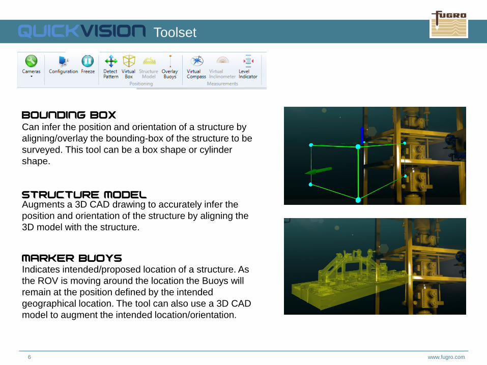
Quickvision Toolset
Bounding Box
Can infer the position and orientation of a structure by
aligning/overlay the bounding-box of the structure to be
surveyed. This tool can be a box shape or cylinder
shape.
Structure Model Augments a 3D CAD drawing to accurately infer the
position and orientation of the structure by aligning the
3D model with the structure.
Marker Buoys
Indicates intended/proposed location of a structure. As
the ROV is moving around the location the Buoys will
remain at the position defined by the intended
geographical location. The tool can also use a 3D CAD
model to augment the intended location/orientation.

www.fugro.com7
Real Time Pattern
Tracking

www.fugro.com8
If patterns are attached to an asset it becomes
possible to:
▪ Automatically track the position, orientation and
attitude of the asset
▪ Track/measure the relative position between two
assets
▪ Navigate relative to an asset
Pattern Targets
• Patterns are stickers, paint etc. of round dark dots
on light coloured backgrounds
• Offset of pattern relative to the asset reference
frame to be measured
• The size of the pattern depends on camera field of
view
Real Time Pattern Tracking

www.fugro.com9
▪ Vessel / Rig / ROV time saving – minimal
calibration required
▪ Real time tracked measurement with QC statistics
enabling efficient decision making
▪ Automated positioning during operations
▪ Minimal user interface during operations
▪ Minimal mobilisation of hardware
▪ Robust technology with no dependency on active
transponder/responder setups
▪ No acoustic interference with measurement
▪ Operationally low risk – no requirement to dock to
assets
Benefits

www.fugro.com10
Track Record
Quickvision has been successfully deployed on six projects in five different regions.
Scope Date Comments
Subsea Construction Support January 2017 Trial of full QuickVision toolkit plus pattern tracking
Topside Installation
(Surface)
May 2017 Surface mounted cameras on HLV deck
Subsea Construction Support June 2017 Pattern Tracking of HIPPS on well
Topside Installation (Surface) September 2017 Surface mounted cameras on HLV deck
UTA Survey November 2017 Monitoring of UTA azimuth
Deviated Conductor Installation October 2017 Monitoring of deviated conductor during installation

www.fugro.com11
Quickvision video demonstrating toolset.
QuickVision

Alastair McKie
Technical Lead Surveyor
T +44 1224 257 458 | M +44 7884 088 723
[email protected] | www.fugro.com