qwertyuiopasdfghjklzxcvbnmq...
TRANSCRIPT

qwertyuiopasdfghjklzxcvbnmqwertyuiopasdfghjklzxcvbnmqwertyuiopasdfghjklzxcvbnmqwertyuiopasdfghjklzxcvbnmqwertyuiopasdfghjklzxcvbnmqwertyuiopasdfghjklzxcvbnmqwertyuiopasdfghjklzxcvbnmqwertyuiopasdfghjklzxcvbnmqwertyuiopasdfghjklzxcvbnmqwertyuiopasdfghjklzxcvbnmqwertyuiopasdfghjklzxcvbnmqwertyuiopasdfghjklzxcvbnmqwertyuiopasdfghjklzxcvbnmqwertyuiopasdfghjklzxcvbnmqwertyuiopasdfghjklzxcvbnmqwertyuiopasdfghjklzxcvbnmqwertyuiopasdfghjklzxcvbnmqwertyuiopasdfghjklzxcvbnmrtyuiopasdfghjklzxcvbnmqwertyuiopasdfghjklzxcvbnmqwertyuiopasdfghjklzxcvbnmqwertyuiopasdf
FURKAN BAŞKURT
PROFESSIONAL PORTFOLIO – 1
EDUCATION & INDUSTRIAL EXPERIENCES
http://web.itu.edu.tr/baskurtf
+90 (535) 523 93 21
This document contains chronological list and details about my B.Sc./M.Sc. education and detailed explanations, technical information, download links for some documents, measurement results (tables, oscilloscope screenshots, pictures, video links, etc…) and
other information related with my industrial experience in electrical engineering.
In case of a question about this document you may contact me via the contact information given above.
PROFESSIONAL PORTFOLIO – 1 1
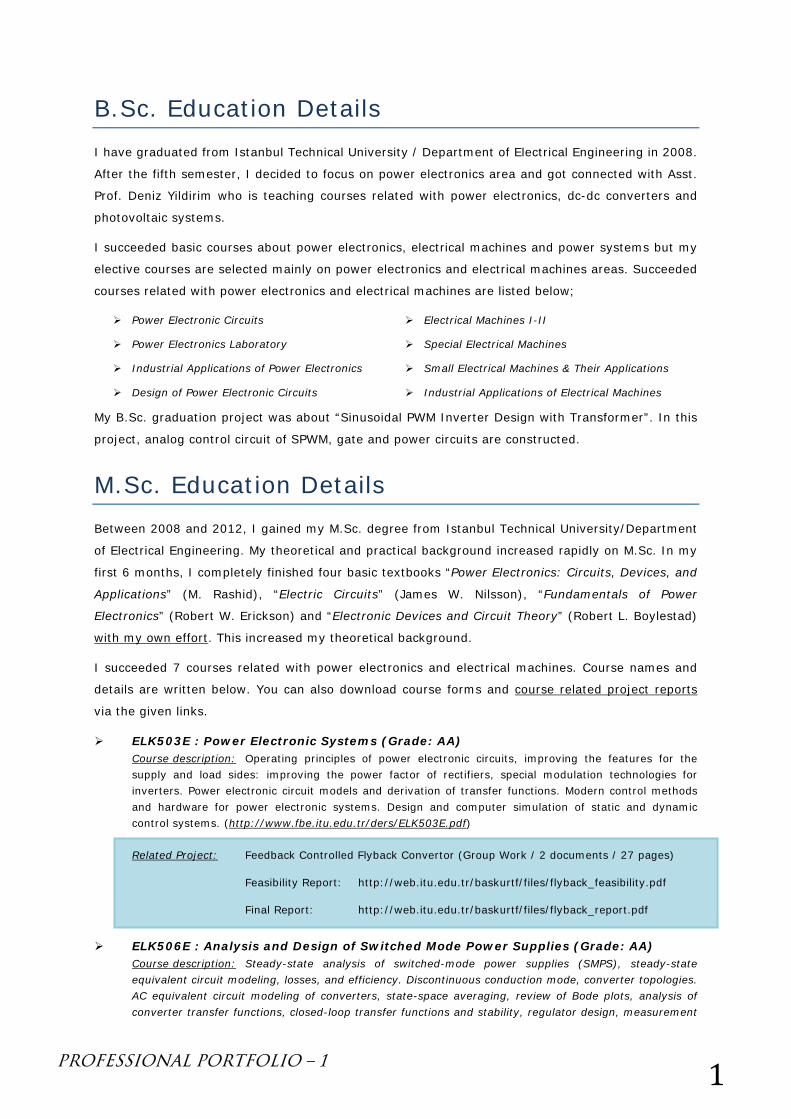
B.Sc. Education Details I have graduated from Istanbul Technical University / Department of Electrical Engineering in 2008.
After the fifth semester, I decided to focus on power electronics area and got connected with Asst.
Prof. Deniz Yildirim who is teaching courses related with power electronics, dc-dc converters and
photovoltaic systems.
I succeeded basic courses about power electronics, electrical machines and power systems but my
elective courses are selected mainly on power electronics and electrical machines areas. Succeeded
courses related with power electronics and electrical machines are listed below;
Power Electronic Circuits
Power Electronics Laboratory
Industrial Applications of Power Electronics
Design of Power Electronic Circuits
Electrical Machines I-II
Special Electrical Machines
Small Electrical Machines & Their Applications
Industrial Applications of Electrical Machines
My B.Sc. graduation project was about “Sinusoidal PWM Inverter Design with Transformer”. In this
project, analog control circuit of SPWM, gate and power circuits are constructed.
M.Sc. Education Details Between 2008 and 2012, I gained my M.Sc. degree from Istanbul Technical University/Department
of Electrical Engineering. My theoretical and practical background increased rapidly on M.Sc. In my
first 6 months, I completely finished four basic textbooks “Power Electronics: Circuits, Devices, and
Applications” (M. Rashid), “Electric Circuits” (James W. Nilsson), “Fundamentals of Power
Electronics” (Robert W. Erickson) and “Electronic Devices and Circuit Theory” (Robert L. Boylestad)
with my own effort. This increased my theoretical background.
I succeeded 7 courses related with power electronics and electrical machines. Course names and
details are written below. You can also download course forms and course related project reports
via the given links.
ELK503E : Power Electronic Systems (Grade: AA) Course description: Operating principles of power electronic circuits, improving the features for the supply and load sides: improving the power factor of rectifiers, special modulation technologies for inverters. Power electronic circuit models and derivation of transfer functions. Modern control methods and hardware for power electronic systems. Design and computer simulation of static and dynamic control systems. (http://www.fbe.itu.edu.tr/ders/ELK503E.pdf)
Related Project: Feedback Controlled Flyback Convertor (Group Work / 2 documents / 27 pages)
Feasibility Report: http://web.itu.edu.tr/baskurtf/files/flyback_feasibility.pdf
Final Report: http://web.itu.edu.tr/baskurtf/files/flyback_report.pdf
ELK506E : Analysis and Design of Switched Mode Power Supplies (Grade: AA) Course description: Steady-state analysis of switched-mode power supplies (SMPS), steady-state equivalent circuit modeling, losses, and efficiency. Discontinuous conduction mode, converter topologies. AC equivalent circuit modeling of converters, state-space averaging, review of Bode plots, analysis of converter transfer functions, closed-loop transfer functions and stability, regulator design, measurement
PROFESSIONAL PORTFOLIO – 1 2
of loop gains. Magnetics theory, loss mechanism in magnetic devices, filter inductor, multiple winding magnetic components, transformer and AC inductor design.
Related Project: DCM Buck-Boost Converter Design (Individual Work)
Presentation: http://web.itu.edu.tr/baskurtf/files/dcm_buckboost.pdf
ELK519E : Resonant Power Converters (Grade: BB) Course description: Introduction to resonant conversion principles, sinusoidal approximation for resonant converter analysis, averaging, state-plane analysis, series and parallel resonant converters, continuous and discontinuous conduction modes, LCC and LLC resonant converter, soft switching, zero-current switching (ZCS) and zero-voltage switching (ZVS) resonant converters, quasi-resonant square wave converters, half-wave and full-wave ZCS quasi-resonant-switch, small-signal AC modeling, analysis of multi-resonant converters. (http://www.fbe.itu.edu.tr/ders/ELK519E.pdf)
Related Project: ZVS Half Wave Quasi Resonant Buck Converter Design (Individual Work)
Final Report: http://web.itu.edu.tr/baskurtf/files/qr_buck_report.pdf
Presentation: http://web.itu.edu.tr/baskurtf/files/qr_buck_presentation.pdf
Video: http://www.youtube.com/watch?v=aLxnqVVTcYE
ELK606E : Brushless Servomotors & Their Applications (Grade: BA) Course description: Definition and classification, electromechanical energy conversion, structure and materials of brushless servomotors, permanent magnet materials and circuits, stepping motors, square-wave permanent magnet brushless motors, sine-wave permanent magnet brushless motors, sensors and digital signal processing for servomotors, power electronic supply circuits, brushless servomotor control, brushless servomotor applications. (http://www.fbe.itu.edu.tr/ders/ELK606E.pdf)
Related Project: Design of an Electric Bike (Individual Work)
Final Report: http://web.itu.edu.tr/baskurtf/files/e_bike.pdf
KOM506E : Control of Induction Machines (Grade: BA)
Course description: Dynamic mathematical model of induction machine for control, state variables and
transfer functions, control features and mathematical models of static power converters used as drivers.
Scalar control methods, field orientation, direct and indirect vector control, modern control applications
in induction machines. (http://www.fbe.itu.edu.tr/ders/KOM506E.pdf)
Related Project: DQ Modeling of an Induction Motor (Individual Work)
Simulation Model: http://web.itu.edu.tr/baskurtf/files/dq_model.pdf
ELK504E : Dynamics of Electrical Machines (Grade: BB) Course description: Principles of electromechanical energy conversion, conservation of energy, flux linkage, field energy, co-energy, induced torque and force expressions, state equations of electromechanical systems, mathematical modeling of electrical machines, reference frame theory, transformation between reference frames, transformed equivalent circuit model of alternating-current machines, linearization of machine equations, dynamic analysis of transformers, direct-current, synchronous and induction machines, computer analysis of single and multi-machine problems. (http://www.fbe.itu.edu.tr/ders/ELK504E.pdf)
Related Project: αβ Modeling of an Induction Motor (Individual Work)
Report: http://web.itu.edu.tr/baskurtf/files/ab_model.pdf
PROFESSIONAL PORTFOLIO – 1 3
ELK507 : Harmonics in Electrical Machines (Turkish) (Grade: AA) Course description: Methods of generating non-sinusoidal voltage waveforms, the type of non-sinusoidal voltage waveforms, Fourier Series, the MMF distribution in the air gap. The equivalent circuits of primary space harmonics. The secondary space harmonics. The calculation of air gap flux for sinusoidal and non-sinusoidal voltage waveform applications. Time harmonics. The deep bar effect. The equivalent circuit for time harmonics. The combined equivalent circuit space and time harmonics. The calculation of copper, iron and additional losses. Computer programs for calculation of machine performance. (http://www.fbe.itu.edu.tr/ders/ELK504E.pdf)
Ph.D. Education Details
I have started my Ph.D. degree at ITU because it is required for being a research/teaching
assistant here. I have succeeded 2 courses related with power electronics and electrical machines.
Course names and details are written below. You can also download course forms and course
related project reports via the given links.
ELK605 : Power Electronic Systems (Grade: BA) Course description: Advances in power electronics, control theory, and microprocessors initiated new research on electrical machines. As a result, electrical machines have become widely used and the new application areas have arisen. In this context, alternating current machines controlled by vector control have become heavily used in industrial applications of developed countries. Therefore, a course in this area is required to prepare our students for research and industrial applications. (http://www.fbe.itu.edu.tr/ders/ELK605.pdf)
Related Project: dq0 Simulink Model of Induction Machine (Group Work)
Scalar Control of Induction Machine (Group Work-Simulation)
Power Factor Correction Methods in Power Electronics (Grade: AA) Course description: The qualified usage of the energy has gained more importance. National and international restrictions and standards have been developed about the qualified and effective usage of electrical energy. In recent years, to fulfill the power factor and harmonics values determined in those standards, intensive academic and industrial studies have been implemented on power factor correction (PFC) circuits. (http://www.bologna.yildiz.edu.tr/ects/index.php?r=course/view&id=7572&aid=4)
M.Sc. Thesis Work Details
My M.Sc. thesis was “Investigation of a Utility-Connected Wind Energy System” (in Turkish). My thesis was a project for a telecommunication company. Base Transmission Stations (BTS) are utility connected systems and within this project electrical system of every individual BTS was decided to be supplied by a medium power (<2kW) wind turbine. Hence, the company wanted to decrease bill values. The suggested system has unidirectional power flow with the utility side (from utility to the BTS). A representative power share system is constructed at laboratory, power electronics converters are designed, and results are tabulated.
Theoretical Works;
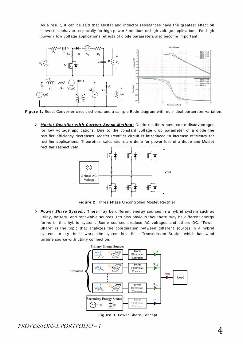
CCM Boost Converter Analysis and Modeling: The static and dynamic models of a CCM boost converter with four non-ideal parameters such as Mosfet ON resistance, inductor resistance, diode ON resistance and diode constant voltage drop are obtained with State Space Model. Effects of these non-ideal parameters on steady state and dynamic behaviors of the converter are shown in a detailed manner.
PROFESSIONAL PORTFOLIO – 1 4
As a result, it can be said that Mosfet and inductor resistances have the greatest effect on converter behavior, especially for high power / medium or high voltage applications. For high power / low voltage applications, effects of diode parameters also become important.
Mosfet Rectifier with Current Sense Method: Diode rectifiers have some disadvantages for low voltage applications. Due to the constant voltage drop parameter of a diode the rectifier efficiency decreases. Mosfet Rectifier circuit is introduced to increase efficiency for rectifier applications. Theoretical calculations are done for power loss of a diode and Mosfet rectifier respectively.
Power Share System: There may be different energy sources in a hybrid system such as utility, battery, and renewable sources. It’s also obvious that there may be different energy forms in this hybrid system. Some sources produce AC voltages and others DC. “Power Share” is the topic that analyzes the coordination between different sources in a hybrid system. In my thesis work, the system is a Base Transmission Station which has wind turbine source with utility connection.
Figure 1. Boost Converter circuit schema and a sample Bode diagram with non-ideal parameter variation.
Figure 2. Three Phase Uncontrolled Mosfet Rectifier.
Figure 3. Power Share Concept.
PROFESSIONAL PORTFOLIO – 1 5
• Experimental Works;
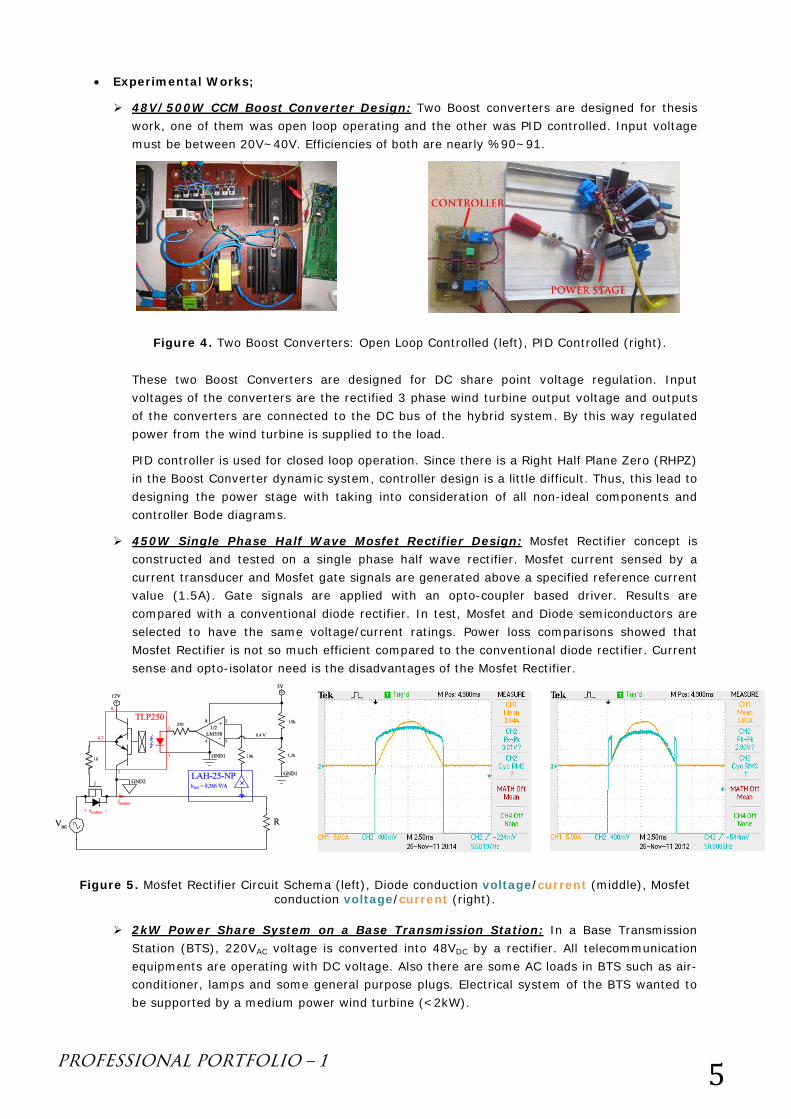
48V/500W CCM Boost Converter Design: Two Boost converters are designed for thesis work, one of them was open loop operating and the other was PID controlled. Input voltage must be between 20V~40V. Efficiencies of both are nearly %90~91.
These two Boost Converters are designed for DC share point voltage regulation. Input voltages of the converters are the rectified 3 phase wind turbine output voltage and outputs of the converters are connected to the DC bus of the hybrid system. By this way regulated power from the wind turbine is supplied to the load.
PID controller is used for closed loop operation. Since there is a Right Half Plane Zero (RHPZ) in the Boost Converter dynamic system, controller design is a little difficult. Thus, this lead to designing the power stage with taking into consideration of all non-ideal components and controller Bode diagrams.
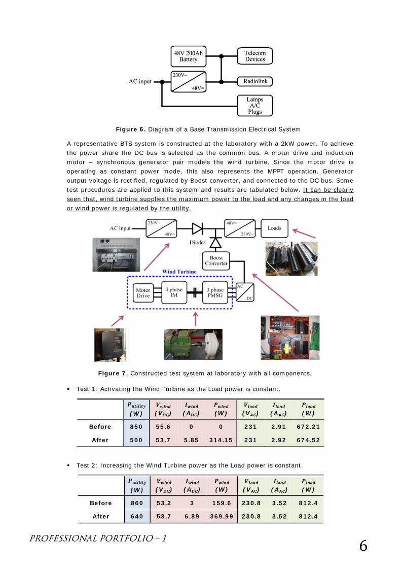
450W Single Phase Half Wave Mosfet Rectifier Design: Mosfet Rectifier concept is constructed and tested on a single phase half wave rectifier. Mosfet current sensed by a current transducer and Mosfet gate signals are generated above a specified reference current value (1.5A). Gate signals are applied with an opto-coupler based driver. Results are compared with a conventional diode rectifier. In test, Mosfet and Diode semiconductors are selected to have the same voltage/current ratings. Power loss comparisons showed that Mosfet Rectifier is not so much efficient compared to the conventional diode rectifier. Current sense and opto-isolator need is the disadvantages of the Mosfet Rectifier.
2kW Power Share System on a Base Transmission Station: In a Base Transmission Station (BTS), 220VAC voltage is converted into 48VDC by a rectifier. All telecommunication equipments are operating with DC voltage. Also there are some AC loads in BTS such as air-conditioner, lamps and some general purpose plugs. Electrical system of the BTS wanted to be supported by a medium power wind turbine (<2kW).
Figure 4. Two Boost Converters: Open Loop Controlled (left), PID Controlled (right).
Figure 5. Mosfet Rectifier Circuit Schema (left), Diode conduction voltage/current (middle), Mosfet conduction voltage/current (right).
PROFESSIONAL PORTFOLIO – 1 6
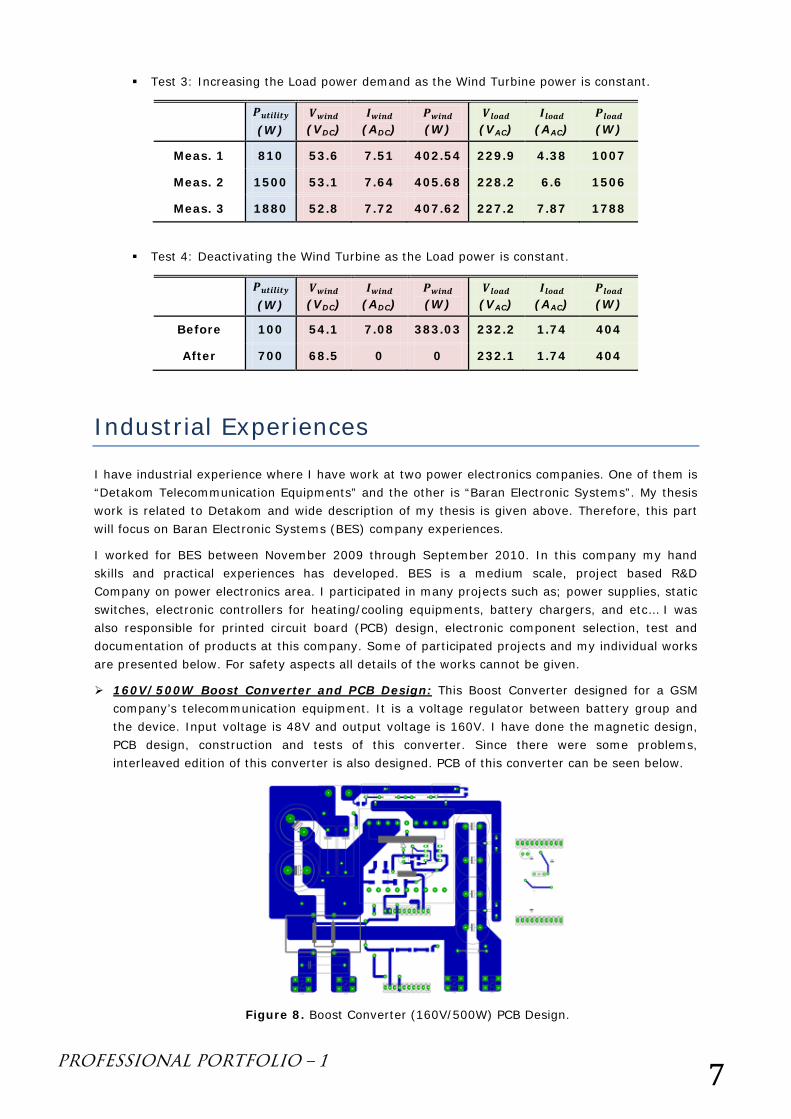
A representative BTS system is constructed at the laboratory with a 2kW power. To achieve the power share the DC bus is selected as the common bus. A motor drive and induction motor – synchronous generator pair models the wind turbine. Since the motor drive is operating as constant power mode, this also represents the MPPT operation. Generator output voltage is rectified, regulated by Boost converter, and connected to the DC bus. Some test procedures are applied to this system and results are tabulated below. It can be clearly seen that, wind turbine supplies the maximum power to the load and any changes in the load or wind power is regulated by the utility.
Test 1: Activating the Wind Turbine as the Load power is constant.
𝑷𝒖𝒕𝒊𝒍𝒊𝒕𝒚 (W)
𝑽𝒘𝒊𝒏𝒅 (VDC)
𝑰𝒘𝒊𝒏𝒅 (ADC)
𝑷𝒘𝒊𝒏𝒅 (W)
𝑽𝒍𝒐𝒂𝒅 (VAC)
𝑰𝒍𝒐𝒂𝒅 (AAC)
𝑷𝒍𝒐𝒂𝒅 (W)
Before 850 55.6 0 0 231 2.91 672.21
After 500 53.7 5.85 314.15 231 2.92 674.52
Test 2: Increasing the Wind Turbine power as the Load power is constant.
𝑷𝒖𝒕𝒊𝒍𝒊𝒕𝒚 (W)
𝑽𝒘𝒊𝒏𝒅 (VDC)
𝑰𝒘𝒊𝒏𝒅 (ADC)
𝑷𝒘𝒊𝒏𝒅 (W)
𝑽𝒍𝒐𝒂𝒅 (VAC)
𝑰𝒍𝒐𝒂𝒅 (AAC)
𝑷𝒍𝒐𝒂𝒅 (W)
Before 860 53.2 3 159.6 230.8 3.52 812.4
After 640 53.7 6.89 369.99 230.8 3.52 812.4
Figure 6. Diagram of a Base Transmission Electrical System
Figure 7. Constructed test system at laboratory with all components.
PROFESSIONAL PORTFOLIO – 1 7
Test 3: Increasing the Load power demand as the Wind Turbine power is constant.
𝑷𝒖𝒕𝒊𝒍𝒊𝒕𝒚 (W)
𝑽𝒘𝒊𝒏𝒅 (VDC)
𝑰𝒘𝒊𝒏𝒅 (ADC)
𝑷𝒘𝒊𝒏𝒅 (W)
𝑽𝒍𝒐𝒂𝒅 (VAC)
𝑰𝒍𝒐𝒂𝒅 (AAC)
𝑷𝒍𝒐𝒂𝒅 (W)
Meas. 1 810 53.6 7.51 402.54 229.9 4.38 1007
Meas. 2 1500 53.1 7.64 405.68 228.2 6.6 1506
Meas. 3 1880 52.8 7.72 407.62 227.2 7.87 1788
Test 4: Deactivating the Wind Turbine as the Load power is constant.
𝑷𝒖𝒕𝒊𝒍𝒊𝒕𝒚 (W)
𝑽𝒘𝒊𝒏𝒅 (VDC)
𝑰𝒘𝒊𝒏𝒅 (ADC)
𝑷𝒘𝒊𝒏𝒅 (W)
𝑽𝒍𝒐𝒂𝒅 (VAC)
𝑰𝒍𝒐𝒂𝒅 (AAC)
𝑷𝒍𝒐𝒂𝒅 (W)
Before 100 54.1 7.08 383.03 232.2 1.74 404
After 700 68.5 0 0 232.1 1.74 404
Industrial Experiences
I have industrial experience where I have work at two power electronics companies. One of them is “Detakom Telecommunication Equipments” and the other is “Baran Electronic Systems”. My thesis work is related to Detakom and wide description of my thesis is given above. Therefore, this part will focus on Baran Electronic Systems (BES) company experiences.
I worked for BES between November 2009 through September 2010. In this company my hand skills and practical experiences has developed. BES is a medium scale, project based R&D Company on power electronics area. I participated in many projects such as; power supplies, static switches, electronic controllers for heating/cooling equipments, battery chargers, and etc… I was also responsible for printed circuit board (PCB) design, electronic component selection, test and documentation of products at this company. Some of participated projects and my individual works are presented below. For safety aspects all details of the works cannot be given.
160V/500W Boost Converter and PCB Design: This Boost Converter designed for a GSM company’s telecommunication equipment. It is a voltage regulator between battery group and the device. Input voltage is 48V and output voltage is 160V. I have done the magnetic design, PCB design, construction and tests of this converter. Since there were some problems, interleaved edition of this converter is also designed. PCB of this converter can be seen below.
Figure 8. Boost Converter (160V/500W) PCB Design.
PROFESSIONAL PORTFOLIO – 1 8
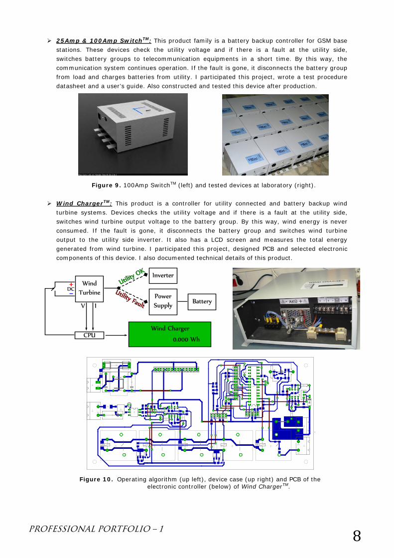
25Amp & 100Amp SwitchTM: This product family is a battery backup controller for GSM base stations. These devices check the utility voltage and if there is a fault at the utility side, switches battery groups to telecommunication equipments in a short time. By this way, the communication system continues operation. If the fault is gone, it disconnects the battery group from load and charges batteries from utility. I participated this project, wrote a test procedure datasheet and a user’s guide. Also constructed and tested this device after production.
Wind ChargerTM: This product is a controller for utility connected and battery backup wind turbine systems. Devices checks the utility voltage and if there is a fault at the utility side, switches wind turbine output voltage to the battery group. By this way, wind energy is never consumed. If the fault is gone, it disconnects the battery group and switches wind turbine output to the utility side inverter. It also has a LCD screen and measures the total energy generated from wind turbine. I participated this project, designed PCB and selected electronic components of this device. I also documented technical details of this product.
Figure 9. 100Amp SwitchTM (left) and tested devices at laboratory (right).
Figure 10. Operating algorithm (up left), device case (up right) and PCB of the electronic controller (below) of Wind ChargerTM.
PROFESSIONAL PORTFOLIO – 1 9
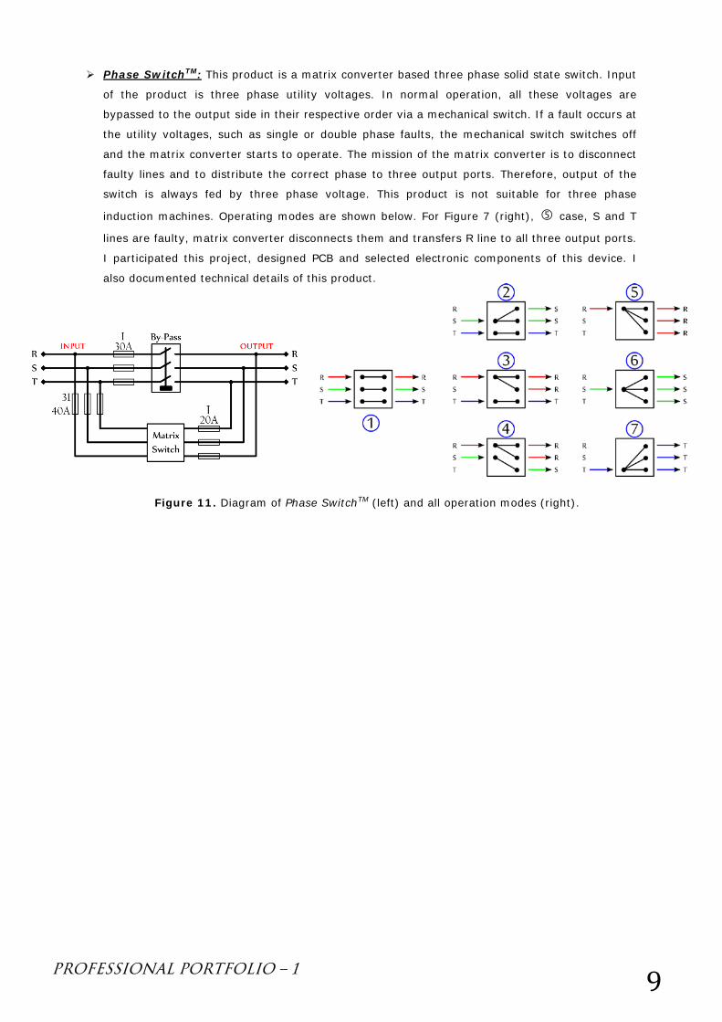
Phase SwitchTM: This product is a matrix converter based three phase solid state switch. Input
of the product is three phase utility voltages. In normal operation, all these voltages are
bypassed to the output side in their respective order via a mechanical switch. If a fault occurs at
the utility voltages, such as single or double phase faults, the mechanical switch switches off
and the matrix converter starts to operate. The mission of the matrix converter is to disconnect
faulty lines and to distribute the correct phase to three output ports. Therefore, output of the
switch is always fed by three phase voltage. This product is not suitable for three phase
induction machines. Operating modes are shown below. For Figure 7 (right), case, S and T
lines are faulty, matrix converter disconnects them and transfers R line to all three output ports.
I participated this project, designed PCB and selected electronic components of this device. I
also documented technical details of this product.
Figure 11. Diagram of Phase SwitchTM (left) and all operation modes (right).

qwertyuiopasdfghjklzxcvbnmqwertyuiopasdfghjklzxcvbnmqwertyuiopasdfghjklzxcvbnmqwertyuiopasdfghjklzxcvbnmqwertyuiopasdfghjklzxcvbnmqwertyuiopasdfghjklzxcvbnmqwertyuiopasdfghjklzxcvbnmqwertyuiopasdfghjklzxcvbnmqwertyuiopasdfghjklzxcvbnmqwertyuiopasdfghjklzxcvbnmqwertyuiopasdfghjklzxcvbnmqwertyuiopasdfghjklzxcvbnmqwertyuiopasdfghjklzxcvbnmqwertyuiopasdfghjklzxcvbnmqwertyuiopasdfghjklzxcvbnmqwertyuiopasdfghjklzxcvbnmqwertyuiopasdfghjklzxcvbnmqwertyuiopasdfghjklzxcvbnmrtyuiopasdfghjklzxcvbnmqwertyuiopasdfghjklzxcvbnmqwertyuiopasdfghjklzxcvbnmqwertyuiopasdf
FURKAN BAŞKURT
PROFESSIONAL PORTFOLIO – 2
ACADEMIC & LABORATORY EXPERIENCES
http://web.itu.edu.tr/baskurtf
+90 (535) 523 93 21
This document contains detailed explanations, technical information, measurement results (tables, oscilloscope screenshots, pictures, video links, etc…) and other
information related with my academic and laboratory experiences. In case of a question about this document you may contact me via the contact information given above.
PROFESSIONAL PORTFOLIO – 2 1
Academic Experiences I have started working at Istanbul Technical University / Department of Electrical Engineering at
November 2010. I am currently research & teaching assistant at Power Electronics Laboratory. Some of
my assisted courses and laboratories are listed in my CV but more details are written in this document.
ELK331E – Power Electronic Circuits (English) – 3 Years Course Content: http://www.sis.itu.edu.tr/eng/content/content.php?subj=ELK&numb=331E
My advisor Asst. Prof. Dr. Deniz Yildirim teaches “ELK331E Power Electronic Circuits” and I have
been the teaching assistant of this course for 3 years. ELK331E is a required course for Electrical
Engineering and Control Engineering students. Average of ~60 students takes this course per year.
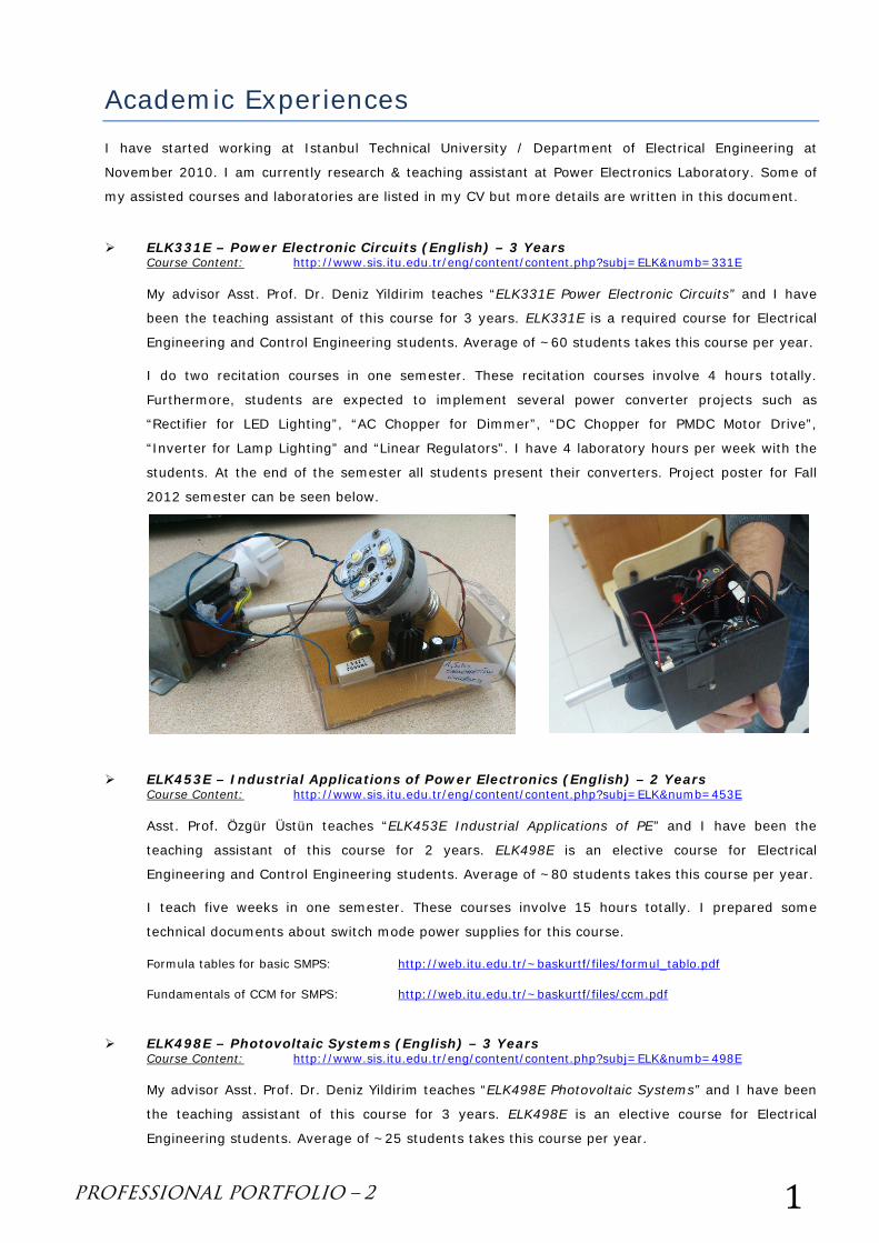
I do two recitation courses in one semester. These recitation courses involve 4 hours totally.
Furthermore, students are expected to implement several power converter projects such as
“Rectifier for LED Lighting”, “AC Chopper for Dimmer”, “DC Chopper for PMDC Motor Drive”,
“Inverter for Lamp Lighting” and “Linear Regulators”. I have 4 laboratory hours per week with the
students. At the end of the semester all students present their converters. Project poster for Fall
2012 semester can be seen below.
ELK453E – Industrial Applications of Power Electronics (English) – 2 Years Course Content: http://www.sis.itu.edu.tr/eng/content/content.php?subj=ELK&numb=453E
Asst. Prof. Özgür Üstün teaches “ELK453E Industrial Applications of PE” and I have been the
teaching assistant of this course for 2 years. ELK498E is an elective course for Electrical
Engineering and Control Engineering students. Average of ~80 students takes this course per year.
I teach five weeks in one semester. These courses involve 15 hours totally. I prepared some
technical documents about switch mode power supplies for this course.
Formula tables for basic SMPS: http://web.itu.edu.tr/~baskurtf/files/formul_tablo.pdf
Fundamentals of CCM for SMPS: http://web.itu.edu.tr/~baskurtf/files/ccm.pdf
ELK498E – Photovoltaic Systems (English) – 3 Years Course Content: http://www.sis.itu.edu.tr/eng/content/content.php?subj=ELK&numb=498E
My advisor Asst. Prof. Dr. Deniz Yildirim teaches “ELK498E Photovoltaic Systems” and I have been
the teaching assistant of this course for 3 years. ELK498E is an elective course for Electrical
Engineering students. Average of ~25 students takes this course per year.
PROFESSIONAL PORTFOLIO – 2 2
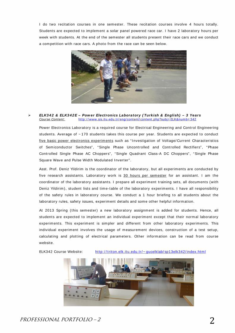
I do two recitation courses in one semester. These recitation courses involve 4 hours totally.
Students are expected to implement a solar panel powered race car. I have 2 laboratory hours per
week with students. At the end of the semester all students present their race cars and we conduct
a competition with race cars. A photo from the race can be seen below.
ELK342 & ELK342E – Power Electronics Laboratory (Turkish & English) – 3 Years Course Content: http://www.sis.itu.edu.tr/eng/content/content.php?subj=ELK&numb=342
Power Electronics Laboratory is a required course for Electrical Engineering and Control Engineering
students. Average of ~170 students takes this course per year. Students are expected to conduct
five basic power electronics experiments such as “Investigation of Voltage/Current Characteristics
of Semiconductor Switches”, “Single Phase Uncontrolled and Controlled Rectifiers”, “Phase
Controlled Single Phase AC Choppers”, “Single Quadrant Class-A DC Choppers”, “Single Phase
Square Wave and Pulse Width Modulated Inverter”.
Asst. Prof. Deniz Yildirim is the coordinator of the laboratory, but all experiments are conducted by
five research assistants. Laboratory work is 30 hours per semester for an assistant. I am the
coordinator of the laboratory assistants. I prepare all experiment training sets, all documents (with
Deniz Yildirim), student lists and time-table of the laboratory experiments. I have all responsibility
of the safety rules in laboratory course. We conduct a 1 hour briefing to all students about the
laboratory rules, safety issues, experiment details and some other helpful information.
At 2013 Spring (this semester) a new laboratory assignment is added for students. Hence, all
students are expected to implement an individual experiment except that their normal laboratory
experiments. This experiment is simpler and different from other laboratory experiments. This
individual experiment involves the usage of measurement devices, construction of a test setup,
calculating and plotting of electrical parameters. Other information can be read from course
website.
ELK342 Course Website: http://triton.elk.itu.edu.tr/~gucelklab/sp13elk342/index.html
PROFESSIONAL PORTFOLIO – 2 3
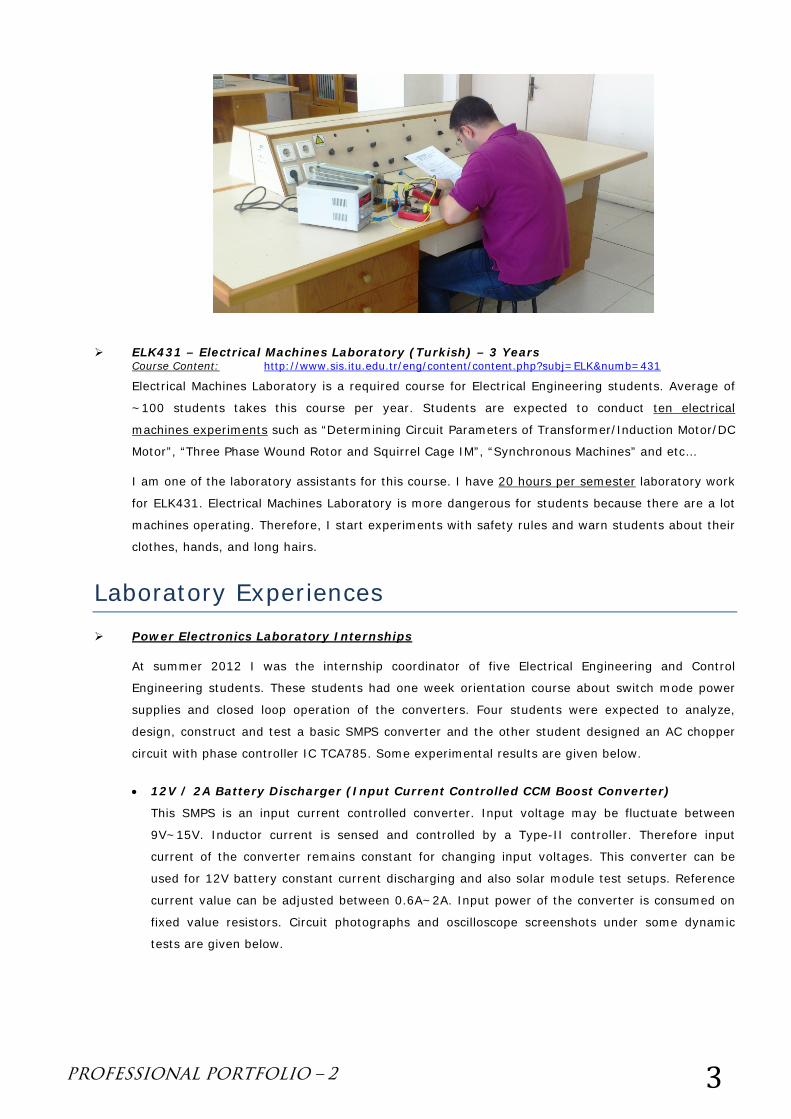
ELK431 – Electrical Machines Laboratory (Turkish) – 3 Years Course Content: http://www.sis.itu.edu.tr/eng/content/content.php?subj=ELK&numb=431
Electrical Machines Laboratory is a required course for Electrical Engineering students. Average of
~100 students takes this course per year. Students are expected to conduct ten electrical
machines experiments such as “Determining Circuit Parameters of Transformer/Induction Motor/DC
Motor”, “Three Phase Wound Rotor and Squirrel Cage IM”, “Synchronous Machines” and etc…
I am one of the laboratory assistants for this course. I have 20 hours per semester laboratory work
for ELK431. Electrical Machines Laboratory is more dangerous for students because there are a lot
machines operating. Therefore, I start experiments with safety rules and warn students about their
clothes, hands, and long hairs.
Laboratory Experiences Power Electronics Laboratory Internships
At summer 2012 I was the internship coordinator of five Electrical Engineering and Control
Engineering students. These students had one week orientation course about switch mode power
supplies and closed loop operation of the converters. Four students were expected to analyze,
design, construct and test a basic SMPS converter and the other student designed an AC chopper
circuit with phase controller IC TCA785. Some experimental results are given below.
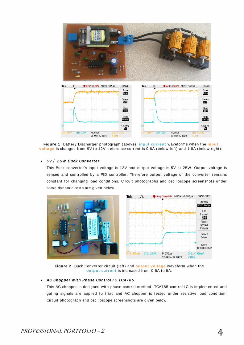
• 12V / 2A Battery Discharger (Input Current Controlled CCM Boost Converter)
This SMPS is an input current controlled converter. Input voltage may be fluctuate between
9V~15V. Inductor current is sensed and controlled by a Type-II controller. Therefore input
current of the converter remains constant for changing input voltages. This converter can be
used for 12V battery constant current discharging and also solar module test setups. Reference
current value can be adjusted between 0.6A~2A. Input power of the converter is consumed on
fixed value resistors. Circuit photographs and oscilloscope screenshots under some dynamic
tests are given below.
PROFESSIONAL PORTFOLIO – 2 4
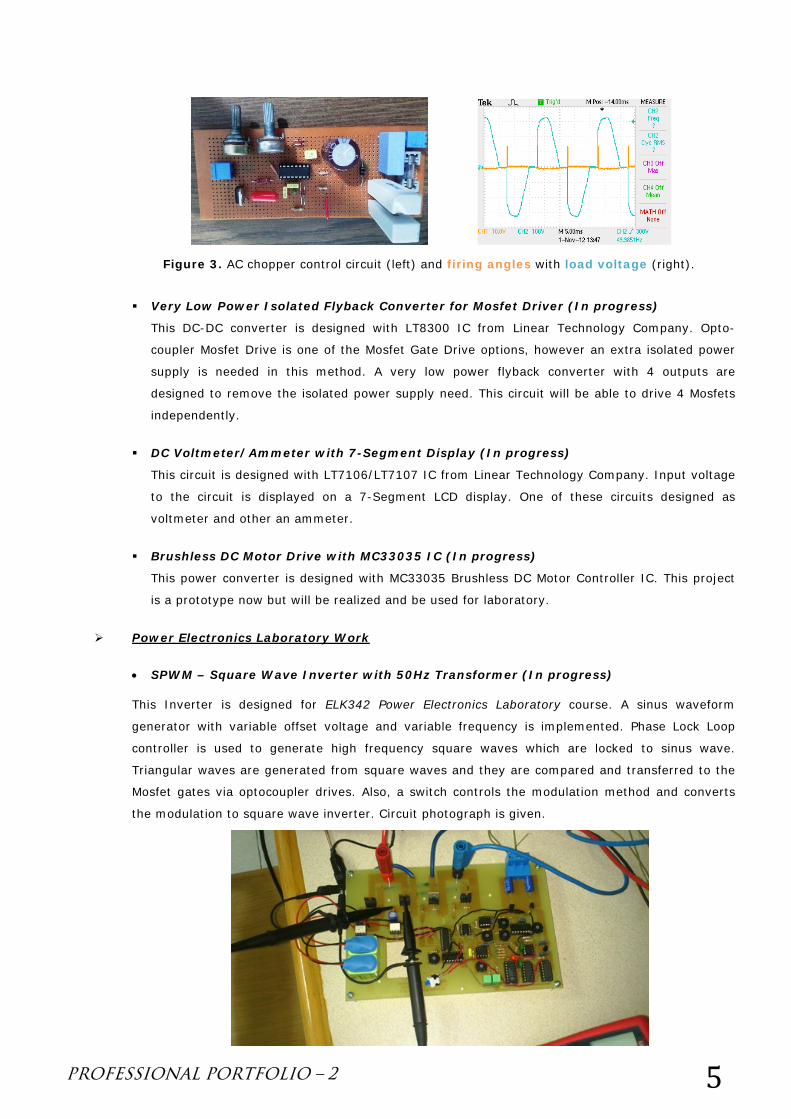
• 5V / 25W Buck Converter
This Buck converter’s input voltage is 12V and output voltage is 5V at 25W. Output voltage is
sensed and controlled by a PID controller. Therefore output voltage of the converter remains
constant for changing load conditions. Circuit photographs and oscilloscope screenshots under
some dynamic tests are given below.
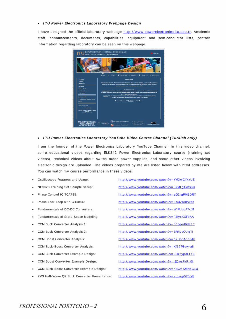
• AC Chopper with Phase Control IC TCA785
This AC chopper is designed with phase control method. TCA785 control IC is implemented and
gating signals are applied to triac and AC chopper is tested under resistive load condition.
Circuit photograph and oscilloscope screenshots are given below.
Figure 1. Battery Discharger photograph (above), input current waveforms when the input voltage is changed from 9V to 12V: reference current is 0.6A (below-left) and 1.8A (below right).
Figure 2. Buck Converter circuit (left) and output voltage waveform when the output current is increased from 0.5A to 5A.
PROFESSIONAL PORTFOLIO – 2 5
Very Low Power Isolated Flyback Converter for Mosfet Driver (In progress)
This DC-DC converter is designed with LT8300 IC from Linear Technology Company. Opto-
coupler Mosfet Drive is one of the Mosfet Gate Drive options, however an extra isolated power
supply is needed in this method. A very low power flyback converter with 4 outputs are
designed to remove the isolated power supply need. This circuit will be able to drive 4 Mosfets
independently.
DC Voltmeter/Ammeter with 7-Segment Display (In progress)
This circuit is designed with LT7106/LT7107 IC from Linear Technology Company. Input voltage
to the circuit is displayed on a 7-Segment LCD display. One of these circuits designed as
voltmeter and other an ammeter.
Brushless DC Motor Drive with MC33035 IC (In progress)
This power converter is designed with MC33035 Brushless DC Motor Controller IC. This project
is a prototype now but will be realized and be used for laboratory.
Power Electronics Laboratory Work
• SPWM – Square Wave Inverter with 50Hz Transformer (In progress)
This Inverter is designed for ELK342 Power Electronics Laboratory course. A sinus waveform
generator with variable offset voltage and variable frequency is implemented. Phase Lock Loop
controller is used to generate high frequency square waves which are locked to sinus wave.
Triangular waves are generated from square waves and they are compared and transferred to the
Mosfet gates via optocoupler drives. Also, a switch controls the modulation method and converts
the modulation to square wave inverter. Circuit photograph is given.
Figure 3. AC chopper control circuit (left) and firing angles with load voltage (right).
PROFESSIONAL PORTFOLIO – 2 6
• ITU Power Electronics Laboratory Webpage Design
I have designed the official laboratory webpage http://www.powerelectronics.itu.edu.tr. Academic
staff, announcements, documents, capabilities, equipment and semiconductor lists, contact
information regarding laboratory can be seen on this webpage.
• ITU Power Electronics Laboratory YouTube Video Course Channel (Turkish only)
I am the founder of the Power Electronics Laboratory YouTube Channel. In this video channel,
some educational videos regarding ELK342 Power Electronics Laboratory course (training set
videos), technical videos about switch mode power supplies, and some other videos involving
electronic design are uploaded. The videos prepared by me are listed below with html addresses.
You can watch my course performance in these videos.
• Oscilloscope Features and Usage: http://www.youtube.com/watch?v=YMXwClfkxUE
• NE9023 Training Set Sample Setup: http://www.youtube.com/watch?v=uYMLg4xbs3U
• Phase Control IC TCA785: http://www.youtube.com/watch?v=eG2rqPMBDRY
• Phase Lock Loop with CD4046: http://www.youtube.com/watch?v=iDOiZKmVSfc
• Fundamentals of DC-DC Converters: http://www.youtube.com/watch?v=WlPUqoA7cJ8
• Fundamentals of State-Space Modeling: http://www.youtube.com/watch?v=F4lyxKXFbAA
• CCM Buck Converter Analysis 1: http://www.youtube.com/watch?v=b5pqed6dLZE
• CCM Buck Converter Analysis 2: http://www.youtube.com/watch?v=BRhycCUigTI
• CCM Boost Converter Analysis: http://www.youtube.com/watch?v=q7DobAnn040
• CCM Buck-Boost Converter Analysis: http://www.youtube.com/watch?v=Kf37P8ew-a8
• CCM Buck Converter Example Design: http://www.youtube.com/watch?v=3DzpypXEFeE
• CCM Boost Converter Example Design: http://www.youtube.com/watch?v=jE0wsPvR_0I
• CCM Buck-Boost Converter Example Design: http://www.youtube.com/watch?v=nBCmSMN4CZU
• ZVS Half-Wave QR Buck Converter Presentation: http://www.youtube.com/watch?v=aLxnqVVTcYE