qxl - federation of american scientists acana detaila of record sections of nevada teot site (nts)...
TRANSCRIPT

,,,,1,.~..!\ .’ I,
LA-UR .80-3012
TITLE: Seismograms of Explosions at Regional Dista,lcss in the
\
Western U. S.: Observations and Refleccivicy MethodModeling
$$$$lt
4UTHOR(S): Kenneth t!. Olsen, G-7Lawrence W. Braile, Purdue bniv. & G-Div, Consultant
SUBMITTED TO: Proceedings Volume of the NATO Advanced StudyInstitute: “Identification of Seismic Sources -Earthquake or Underground Explosion. ” (Held8- 18 September 1980, Oslo Norway)
CG.-C
?5.-
0>.-(n
g.-
5
I)yilcu!lllmlco of tlll$ Ottl(ll , Ill!, l)(lt)ll\llltr 11,( ()(Jrll/l~\ 111,1! till!
() S, (;t]vI, If1tw13t rol{)lll,, o !IOI)0,V(I!,S,4V03, I,)yjIIIy f,,,,, 11,,,,,,,,
to I,(lt)ll’,h or Il,l)fod(lct! tl!u l)(lllll\lll$lt f[)fttl of !114$ , olltttl)(l
11011, or 10 illl IIw [)tlwm to II{) \(I, III! () S I;(Iv I, 1111711sIII I)tlr
IX)W!3
11),, I [)$ AI OITN)$ SC IPI\IIfI(: Lnl)ornt OIy II (11111$1$11101tl](~ l)(d)
lI~tItIr I!hIIIt IfV IIII! iIr IIcl I! m work I1o II I)r IIwIt !jt\,lt, r tlw ,1(1$
IIICPf of 11111L) !; [)!,l)iittl!rt, !!t of 1 I Ilr,;{
Qxl LOS ALAMOS SCIENTIFIC LABORATORYPostOfficeBcx16f/3 Los Alamos, N~w Mexico87545
An Affirm&tiveActic,l):F.qualOpporWity
I 01111 N(), 11.hi 1{,1
!;!, No, ,II!;J!)1;~l /}1

SEISM~RAi4S OF
UNITED STATES:EXPLOSIONS AT REGIONAL DISTANCES IN THE WESTERN
OBSERVATIONSMD REFLEXIVITY METHODMODELING
K. H. Oleenl and L. W. Braile2
1 Geosciences Divi8ion, LOO Alamon ScientificLaboratory, Lo- Alamos, New Plexico 87545, U.S.A.
2 Geoscience Department, Purdue University,West Lafayette, Indiana 47907, U.S.A.
ABSTRACT. Seismic ●uergy propagating through vertically ●ndlaterally varying structures of the ●arth’s crumt ●nd lowerlithosphere-.uppermoot mantle is responsible for the numerous ●ndcomplex seismic Phaors observed on short-period seiomograma atregional distance ranges (100 to 2000 km). Recent adv..ncea intechniques for computing synthetic ●eimogram~ make it practicalto calculate complete tcismograms that realistically model manyfeaturee of regional phases. A ❑edified reflectivity methodprogram is used to interpret acana detaila of record sections ofNevada Teot Site (NTS) underground ●xplomionm that were observed700 to 800 km from the eourceo.
1, INTRODUCTION
Regional meimmic phases recorded by high-gain, ●hort-period orbroadband instruments ●re likely to play ●n increasingly im-portant role in ●eiamic source location ●nd identification asacceptable magnitude threthold~ ●re pushed to lower levels.From the standpoint of complexity of seismograms, the epicentraldistance range between ’200 km and the transition to simplerteleseismic waveformo ●round 2000 km presents many challenges tothe seismic ●nalyst. In thic range, propagation pathe cantraverse the crust, the lower lithosphere, and the uppermcmtmantle where both vnrtical and lateral heterogeneities stronglyinfluence waveform characteristics. Good observational data ●rerare for te-ting analysis techniques developed for r~gionalproblems. In contrast to the nunrouc detailed crumtalrefraction/reflection pL’ofilas that have been obtained from manyparts of the world out to diotances ’200 km, relatively few

long-range profiles exist where station spacing is sufficientlytight to facilitate a clear interpretation of the onset,development , and amplitl~de vs. dititance behavior of the many
observable phases. Thus , although sig~als from sources ofinterest may be easily obser~-able at regional distances,derivation of source parameters from observations at sparselylocated observatd’ries or r.rrays will require careful ailalysisand modeling of the intricacies of wave propagation at thesescales.
Phases of interest in regional identification studies fall
into two main categories: large amplitude, long duration, butsomewhat indistinct w,~ve groups such as Lg and ~; and body wcves
(mainly compres~ional) that appear either as first arrivals orclosely following as possible wide angle r~flections/near-critical refractions from interfaces and/or steep velocitygradients in the deep- crust., lower lithosphere, and uppermostmant le. The Lg and ? phases are often the largest amplitudefeatures on regional seismogran(s, but a clear explanation of howLg and ~ propagate is still lacJing [1]; this lack perhaps isreflected in the fact that the P phase is sometimes inappropri-ately called ~g in the liter~ture. The grou~ velocities(-3.5 km/s f~r Lg, ‘6.0 km/s for P) imply that Lg (P) propagatesas shear (congressional) waves multiply reflected within thecrust---which may thus act as a waveguide,
of high~~n’jo~~tyo~~ ~~jprefer to trest Lg as a superpositionRayleigh waves propagating in a nearly laterally homogeneous,vertically layered crust. ln any case, the propagation physicsis complicated and will require quite sophisticated syntheticseismogram codes to properly mode: and intexpret observedwaveforma.
Record sect;ons of long-range seismic refraction profiles
often show one or more nearly parallel travel time (T) VS.
distance (A) branches following witk,in several seconds of firstarrivals [3, 4, 5]. Each secondary branch may be traceable onlyover a distance interval of 50 to 200 km bet~re being replacedwith another branch or set of arrivals [5, 6]. These- areusually interpreted as parts of cusp phases arising from criticalrefractions andlor wide-angle reflections from first orderdiscontinuities or steep velocity gradients in the upper mantle.
Archambcau ?t al, 17] and Burdick and Helmberger [8], forexample? have derived velocity vs. depth models for the majorfeatures of the upper manLle beneath the U.S. by a joint analysisof travel times, amplitude vs. distance variations, and wqveformfitting of the first few compressional arrivaln obeerved atwidely separated seismograph stations ti>roughout the U.S. Theseand similar models by others are most valid for depths greaterthan about 250 km, Alt!~ough these analyses suggest that themain features of mantle structure at depths below about 300 km
(corresponding to compressional first arrivals at epicentral
ranges beyond 1500 km) may be more uniform over a global scale[8], it is known that significant lateral variations in lowerlithosphere and uppermost mantle properties occur beneath thecontinents on regional and perhaps aven finer scales [8, 9, 10,11]0 In the depth range between the Moho and 300 km, severaltypes of structural variations have been sugge?ted in the litera-ture that would give rise to wide angle reflections, convertedphases, and similar closely spaced arrivals on seismograms atregional ranges. These include the presence or absence of theS-wave andlor the P-wave low velocity zone (LVZ) in theathencsphere, high velocity mantle lids [12, 13], alternatinglamellae of positive and negative velocity gradie~ts [6], etc.These early arriving phases often have better defined onsetsthan the P and Lg phases and, since they are observed atdistances beyond that where a true head wave Pn arrival can beexpected, ?hey may be useful in regional source locatioi? andidentification. In order to make uae of the informationcontained in these arrivals (especially the amplitude vs.distance behavior for particular paths of interest), it will benecessary to use modern sophisticated synthetic seismogramtechniques to derive lccalized fine scale details fromgeneralized crust-mantle models.
The purpose of this paper ig to explore a few of theproblems in modeling regional short-period seismograms by meansof a modified reflectivity method [14] computer programdeveloped by R. Kind [15]. This numerical progvam accounts forthe effects of a buxied source and is thus capable of computing‘complete’ seismograms --including surface reflected body wavesand surface waves. The effects of anelastic attenuation (Q) foreach layer are included as an integral part of the r,lethod[15].The most severe limitation of the technique for studies ofregional seismograms is the assumption of ~dteral homogeneity(this is also a limitation for normal modes summationtechniques), An item of interest will be the extent syntheticscan be made to match observed waveforms under this restriction.
Two problems are considered, The first, labeled the B-3model for brevity, employs a simple model consisting cf threelayers in the crust without velocity gradients and an almostuniform velocity ❑antle. A large ranpe of apparent eurfacephase velocities is used in order to display S phaaes andsurface waves. The second calculation, the A-10 model, treatsthe mantle structure in detail, but confine$ attention tocompressional phases near ther start of the seismogram. The
more important conclusions of the A-10 model ore summarizedhere--a fuller discussion of this calculation and the implica-tions for uppermost mar,tle structure beneath the weotern U.S.can be found in a previous publication [16].

A comparison of the synthetic seismogram calculations hasbeen made with a 100-km-long record section of short-periodvertical component seismograms obtained in eastern Idaho during
the i9?8 Yellowstone-Eastern Snake River Plains (Y-ESRP) seismicprofiling experiment. For these observations, the sources wereunderground nuclear explosions at the Nevada Test Site (NTS) atdistances between 720 and 820 km from the nearly radiallyoriented linear station array (Fig l). Only the records fromthe largest NTS explosion, the %= 5.7 RUMMY event at1720:Og,076 GMT, 27 September 1978, are reproduced here sincethey have the best signal-to-noise ratio of the three NTSexplosions observed during tkz experime~t. Additional details
of the Y-ES!IP instrumentation, experiment, and data can be foundelsewhere [16].
As discussed by Kind [15] and by Fuchs and Miiller [14], the
reflection coefficient and time shift calculations are carriedout in the frequency domain and then Fourier transformed to plotseismograms. We included Muller’s [17] earth flatteningapproximateion in both of our problems to account for earthcurvature effects. Both P and S velclcities are independentlyspecified in all calculations, since the c:flection coefficientsare functions of both P and S velocity contrasts at non-normalincidence angles and are required even when only computing Pphases over a narrow time window. In the A-10 calculation, forexample, the departure C! the P/S velocity ratio in a layer fromthat given by Poisson’s rat~,o = 1/4 is an important factor inour interpretation [16]. Densities arc given by a Birch’s Lawrelation (density = 0.252 + 0.3788*P velocity), The attenuationfactor Qa for P waves was chosen as 25 in the source layers, 200in the upper crust, and 1000 in the lower crust and the upper-most mantl~ layers; for the LVZ modeling of the A-10 model, (&in the athenosphcric layers was adjusted as part of the fittingprocedure (see Fig. 5). The attenuation factor for S waves wasalways assumed to be 4Qa/9. The explosive eource algorithm [16]was used with the source buried at a depth of C.(AO km in alayer of P velocity = 3,55 km/s, These were close to actualfield values for the NTS RUMMY ●xplosion. Time intervals,n~lmber of samples, and computed len~tha of seismograms werechosen so that the dominant frequency of the eource spectrum wan1.6 Hz for the A-10 calculation--again close to the obqervedvalue, In order to save computer time for the extended d~lrationB-3 seismogram eections, the parameter wer~ chosen so that thedominant frequency of the source was shifted to 0.25 Hz;although this was low, WP felt it w~B adequate for the puposesof this initial study. To avoid long computer rune, th? wave
field was only computed within a limit~d phase velocity window;
1 km/s to 20 kmfs for B-3, and 6.5 km/s to 10CO km/s for A-10.These integration limits sometimes introduced spurious singlecycle “phases” at these apparent velocities in the computedrecord suctions. The limit velocities were chosen so as to notoverlap or interfere with arrivals of interest in theobservations . In the record section plots, the amplitudes ofeach trace have been multiplied by station distance to maintaina convenient scpling of the cpreading phases.
3. DISCUSSION
3.1 The Extended Time Seismograms> B-3 Model
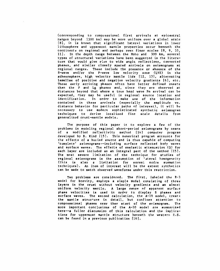
Figure 2 is a true relative amplitude vertical component record
section of the RUMMY explosion recorded on ten matched short-period (1 Hz natural frequency) instruments deployed in theeastern Snake River Plains (Fig. 1). Although the time scale istoo compressed to reveal many details of the waveforms, severalimportant overall features can be noted. The broad (-40-second-lo~g) envelope of the ~ phasp appears at reduced times betweenapproximately 30 to 60+ seconds, and is the largest amplitudefeature on the record. In contrast, the Lg phase expected atreduced time’s of -130+ seconds (an avera~e velocity of about 3.5km/s) is poorly rleveloped c;, these unfiltered records; it isonly obvious at the 770-km station. A few impulsive arrivalscan be seen (such as the first arrivals at reduced time -10seconds, which will be discussed in Sec. 3.2, and perhaps an Sn
[ ] phase at tred-?o seconds and A>78(I km), but the imPres-s~n one gets by viewing this observed section is that thecorrections seem to be better described as broad energycorrelations rather than phase correlations. A sirilar con-clusion is suggested by seismograms from central Asia shown inthe paper of Ruzaikin et al, [11. A coherent structure in the Pand Lg phases IS difficult to trace from station to station eventhough the stationa are only separated by 8 km on the average.
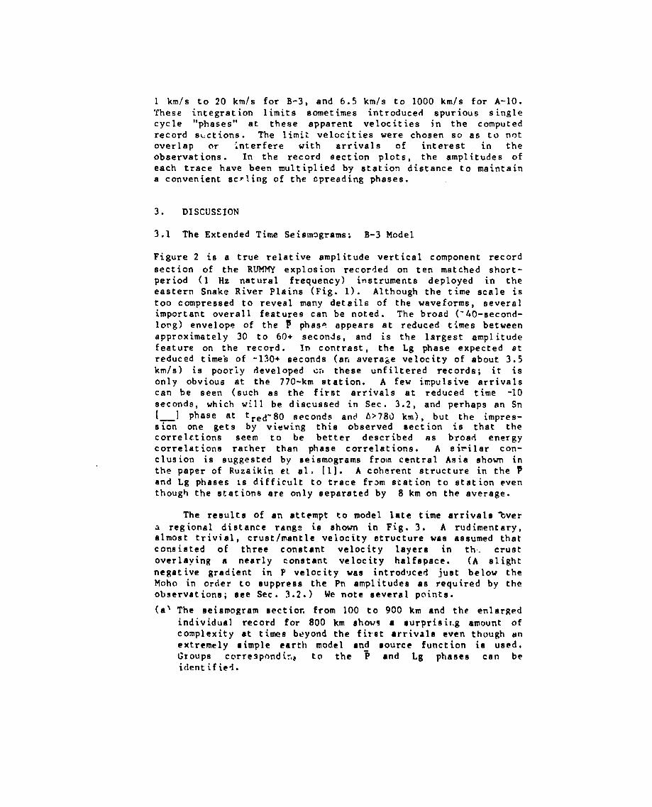
The results of an att?mpt to model late time arrivals %ver
a regional distance range ia shown in Fig. 3. A rudimentary,almost trivial, crust/mantle velocity ~tructure waa assumed thatconsisted of three constant velocity layera in th. crustoverlaying n nearly constant velocity halfspace. (A slightnegative gradient in P velocity was introd~jced just below theMoho in order to suppress the Pn amplitudes aa required by theobservations; aee Sec. 3.2.) We note several points.
(a’ The seismogram oectior, from 100 to 900 km and the enlarged
individual record for 800 km shows ● aurprieit.g smount ofcomplexity at timee beyond the firet arrivals even though anextremely nimple earth model ●nd source function is used,Groups correspr)ndir,c to the ~ ●nd Lg phaaes can beidentified.
(b) There appears to be a considerable amount of S-wave energy
although none is pcresent in the explosion source algorithm.This is probably due to P-to-J and S-to-P, etc., conversionsat interfaces and to multiples the program adequatelyincludes.
(c) The calculated dispersed fundamental mode Rayleigh wave is
very large. There are at least two reasons thie Rayleighwave is not representative of the observations. First, nocorrections for the short-period bandpass response of theseismometers were included in the synthetics. Second,because of limitations on computer time and storage, theassumed source spectrum has too much energy at t?e longer
periods, over enhancing the Rayleigh waves. Long-periodRayleigh waves from actual underground explosions are
probably generated or enhanced by mechanisms such as spanclosure and/or tectonic strain release; these mechanisms arenot treated by the explosion algorithm used for the presentcalculation.
(d) Because the calculated seismograms are quite complicatedeven for this simple earth model, they give the impressionof “energy correlation” rather than phase correlation for atleast the ~ and Lg phases as was the case with the observa-tions in Fig. 2. In order to better understand the grossbehavior’ of these phases with distance and to identify theorigin of obscure features, it will be necessary to includecalculations of the horizontal (radial) component.
These results suggest that tl”temodified reflectivity method,even with the restrictive assumption of lateral homogeneity, canbe a useful technique in understanding the intricacies of Lg andP phases and the types of earth structures that most affect them.Paramete! studies would help identify those aspects where refine-
ments due to lateral heterogeneity andlor scattering need to beconsidered in order to better match observations.
3.2 Early Time Arrivals: A-lo Model
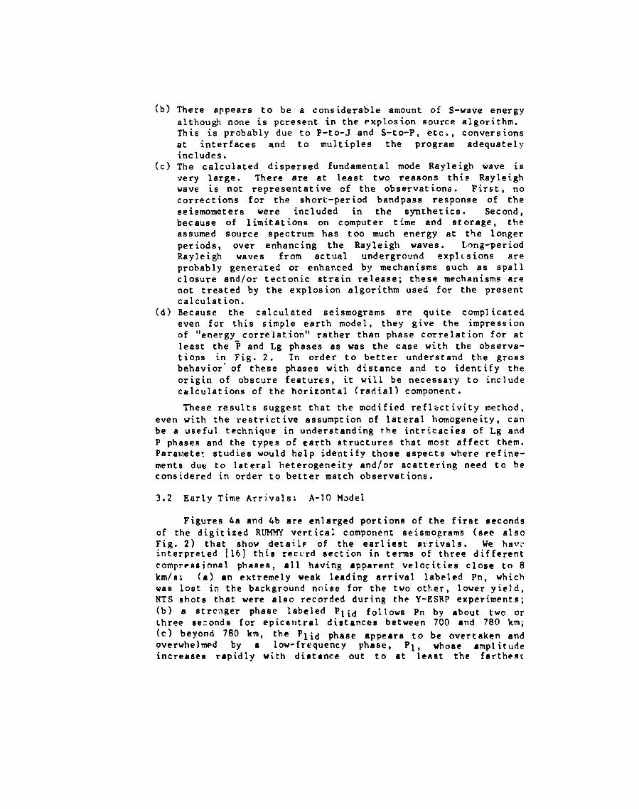
Figures 4a and 4b are enlarged portions of the first oecondsof the digitized RUMMY vertical component seismograms (see alsoFig. 2) that show detailp of the earliest al’rivals. We hav?interpreted [16] this reccrd section in terms of three differentcompregsional phases, all having apparent velocities close to 8
km/s: (a) an extremely weak leading arrival labeled Pn, whichwas lost in the background noise for the two ott,er, lower yield,NTS shots that were also recorded during the Y-ESRP experiments;(b) a strcnger phase labeled plid follows Pn by about two orthree se:onds for epicentral distances between 700 and 780 km;(c) beyond 780 km, the p~id phase appears to be overtaken andoverwhelnwd by a low-frequency phase, Pl, whose amplitudeincreases rapidly with distance out to at le~st the farthest
station of the linear array. The detailed reasons for these
labels and identifications are discussed in [161; tht, can besummarized as follows.
The phase labeled Pn could be a wide angle reflection from
a weak P-velocity contrast in the lower lithosphere below theMohc rather than a true headwave (in the strict sense of themathematical definition) that travels along the M-discontinuityinterface over the entire 800-km path. However, ince the
sub-Moho P velocity (7.7 to 7.9 km/s) in this region of theGreat Basin is known to be close to both the average and theapparent velocity observed in Figs. 2 and 4, plus the fact thatother travel time arguments [16] suggest there is no evidencefor mantle lids or other thin but fairly high gradient zonesdown to a depth of about 100 km, argues that the most straight-
forward explar! ion for this arrival is that it is a pn-typephase. The energy at 800 km is greatly reduced because the wavetravels in a region beneath the Moho that has a slight butnegative gradient.
The sudden onset at about 780 km and subsequent rapid
amplitude growth of the PI phase indicates it is the cusp ofthe critically refracted P-waves from the steep velocitygradient at ‘the base of thz athenospheric low velocity zone.The observed dominant low frequency content is then easilyexplained by the attenuation of the high frequency components asthe energy travels first downward and then back up through the
very 1ow-Q region of the LVZ. The notation of P1 for thisphase follows the convention established by Archambeau et al.[7].
The travel times, moderate amplitudes, and relatively high
frequzncy content imply the phase identified as plid is a wide
angle reflection from a discontinuity near the base of themantle lid (= top of LVZ) in this area.
The conclusions concerning these three early arriving
compressional phases summarized above were confirmed by usingthe modified reflectivity program to quantitatively model thearrival times, amplitudes, and waveforms in the first 15 secondsof the record sections. The procedure was to begin with a~eneric P-velocity vs depth model for the western U.S. (the T-7model) derived from a wider data set by Burdick and Helmberger
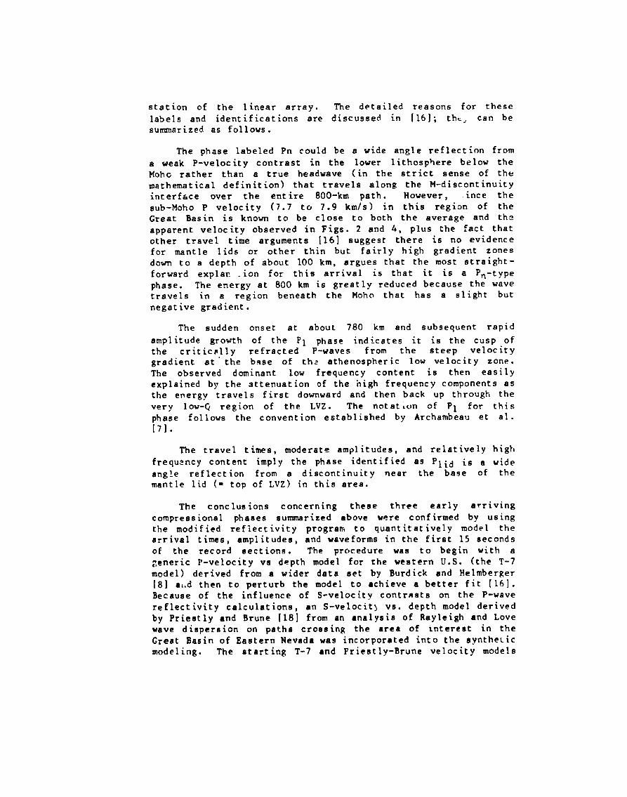
[8] at.d then to perturb the model to achieve a better fit [16].Becauae of the influence of S-velocity contrnsts on the P-wavereflectivity calculations, an S-velocit} vs. depth model derivedby Priestly and Brune [18] from an ●nalysis of Rayleigh and Lovewave dispersion on paths crossing the area of tntereat in theGreat Basin of Eastern Nevada was incorporated into the syntheticmodeling. The starting T-7 and Priestly-Brune velocity models

are shown by dotted lines in Fig. 5. The generic T-7 P-wavemodel has a pronounced mantle lid with a strong positiveP-velocity gradient beneath the Moho for depths from 33 to 65km. Calculation of synthetics for this lid structure gave verylcrge amplitudes for the “pn” arrival, which WaS superimposedon a strong reflection from the base of the lid at 65 km [16].Thus, the T-7/Priestly-Brune starting model gave results verydifferent from observations. To bring the calculated syntheticseismograms into agreement with observations, the gradient atthe base of the LVZ had to be raised to shallower depths and thepositive gradient lid replaced with a smooth but gradual nega-tive gradient starting at the M-discontinuity. The final model,A-10, that matches observations is shown by the solid lines inFig. 5. Figure 6 is the comparison between the observed andsynthetic record sections. Interestingly, no discontinuity inp-VelOCity iS necessary to eXplain the p~id ref~e~tions; thereflections can be adequately modeled by a small negative stepin S velocities at a depth of about 100 km. The synthetics,however, do not seem to adequately ❑odel the long oscillatorytrains following the P1 phase onset. This is probably due toir,terference effects caused by fine structure in the lower LVZvelocity gradient that we have not yet modeled by thin enoughlayers in the calculation [i6j.
These calculations illustrate that synthetic modeling tech-
niques can be helpful in phase identification and in quantitativecalculations of amplitude v;. distance behavior and waveformcharacteristics. With a sophisticated reflectivity methoJcalculation we were able to model several important features of
regional short-period seismograms. The technique appearspromising in advancing knowledge of wave propagation and sourceidentification at regiorIaldistance ranges.
ACKNOWLEDGMENTS
We especially thank Rainer Kind for making avaiiable to us the
modified reflectivity method computer prog?am that we haveadapted for our analyses. Paul A. Johnson was responsible forthe computer runs. The calclllational and data reduction effortsfor this research were supported by the U.S. Department ofEnergy and partially by ONR Earth Physics ProgramNOOO14-75-C-0972 to L.W.B.
grant
The Snake River Plains data werecollected during research partially funded by the U.S. NationalScience Foundation (grant EAR-77-23707 to the University of Utahand EAR-77-23357 to Purdue University) and by the U.S.G.S.Geothermal Exploration Program grant 14-08-0001-G-532 to Purdue.

FIGURE CAPTIONS
Fig. 1. (a) Location map of the western United States with
relative positions of the Nevada Test Site and tie Y-ESRPrecording line. (b) Enlargement showing pos:.tions of stationsthat recorded the 27 September 1978 RUMMY explosion. Asteriskdenotes approximate area for mantle ray turning points from NTSexplosions.
Fig. 2. Low time resolution seismic record section of the RIUMMY
explosion as recorded at Snake River Plains stations. Upwardaround motion to the left.
Fig. 3. (a) Synthetic seismogram vertical component recordsection calculated from the P and S velocity vs depth structure(Model B-3) shown in (b). (c) Expanded plot of the syn:heticseismogram at the 800-km distance. Approximate arrival time andaverage velocity windows for different phases or groups areindicated.
Fig. 4. (a) True relative amplitude record section of earlycompressional arrivals from the RUMMY explosion. (b) Same as(a) with increased amplitudes to show weak Pn Phase. Up&ardmotion to tn’e left. All traces bandpass filtered between O and3 Hz.
Fig. 5. P-velocity (a) and S-velocity (13) vs depth plots forthe T-7/Priestly-Brune and A-10 models. Assumed Q structure atleft: u is Poisson’s ratio.
Fig. 6. Comparison of the observed (a) record section with thesynthetic section calculated from the A-10 model (b).

REFERENCES
1.
2
3.
4.c~.
6.7.
8.
9.
10.11.
12.
13.14.
15.lb.
17.18.
A. 1. Ruzaikin, I. L. Nersesov, V. I. Khalturin, and P.
Molnar, J. Geophys. Res. 82, pp. 307-316, 1977.L. Knopoff, F. Schwab, K. Nakanishi, and F. Chang, Geophys.J. R. astr. Sot. 39, pp. 41-70, 1974.V. Z. Ryaboi, Izv. (Bull.) Acad. Sci. USSR, Ceophys. Ser.,
AGU Trans. 3, PPO 177-lfJ~* 19f560R. P. Masse, Bull. Seism. Sot. Am. 63, pp. 911-935, 1973.
A. Hirrt, L. Steinmetz, R. Kind, and K. Fuchs, Z. Geophys.39, p?. 363-384, 197:,R. Kind, J. Geophys. 40, pp. 189-202, 1974.C. B. Archambeau, E. A. Flinn, and D. G. Lambert, J.Gcophys. Res. 74, pp. 5825-5865, 1969.L. J. Burdick and D. V. Helmberger, J. Geophys. Res. 83,pp. 1699-1712, 1978.J. E. York and D. V. Helmberger, J. Geophys. Res. 78, pp.1883-1886, 1973.M. Cara, Geophys J. R. astr. Sot. 57, pp. 649-670, 1979.B. A,. Romanowicz and M. Cara, Geophys. Res. Lett. 7, PP.
417-420, 1980.A. L. Hales, Earth and Planet. Sci. Lett. 7, pp. 44-46,1969.D. P. H;ll, Geol. Sot. Am. Bull. 83, pp. 1639-1648, 1972.K. Fuchs and G. Mtiller, Geophys. J. R. abstr. SCC. 23, PP.
417-433, 1971.R. Kind, J. Geophvs. 44, pp. 603-612, 1978.K. H. Olsen, L. W. Brails, and P. A. Johnson, J. Geophys.Res., sh.tmitted for publication 1980.G. Muller, J. Geophys. 42, pp. 429-436, 1977.K. Priestly and J. Brune, J. Geophys. Res. 83, pp.~~65_2272.

m
&&2?E!b(a)
llW
IL-J I
5E1s?lIcslnTIas/
1
llSU llW
(b)

. .
240r
740 760 780OISTQNCE [?irl
RUMMY
800 a201
Y-SRP

240
220
200
180
_160
2140
ylzo
:100
[“dO -
6040
20
0
oloo2003004m 6m6m700mo 9mi~X [KM) Z-COW. SYtWIL B-3
(a)
[
Fll NDAMENTAI,
M[ll.l’ll)l,lts, I{ AYI. KI(; II
(’ONVttl(SloNS, ”l’*, II(, s I,u (?)
& IT
–+ A!~ALs__~ ~t
~ ~.l[i
4111-l-----l---l---”l----! ‘9. ‘7 () (+() rlrl rl(~ 4 rl 4(I 3 rl :1()
4 60V f KF1/S1
(b)
, m
F!l{urt!“j

20 ,
15
rP
10 !i!
(
, ,OL700 720 740 760 780 800
● n DISTRNCE fKtll
P t
B
I
‘q---“ (
----Pn
) .820 840
cl)
(b)
700 720 740 760 780 800 820 840DISTFINCE :Ktll
RUMMY

VE1.OCITY (KM/S)
Qi
L~
I1
I 1 1 I I
A– 10
T7+P/B ------------
Figure 5

w
I
m
15
10
5
c700 720 740 760 780 800 82!) 840
fJ~sTQNcE [Km]
(a)
7m 760 840
x IKMI I-Ctltfp. SYW?L Q-10
(b)