r a q-jei j.^.-^^^^^^^j-^f^'-.^.-b f —.js^fc.j ... · the astronautics laboratory, ... state...
TRANSCRIPT

\ /
r A Q-JE- F LL E- a.« .jr-«g- B^ .fa- . i J. .- ^^^^^^J- f '-. .B —.js^fc.J.^.'-'- '^^^^ji.^.f.t-fT.vj^.
COPY
S COMfV«/VV
i
https://ntrs.nasa.gov/search.jsp?R=19730008919 2018-07-28T13:36:11+00:00Z

Page Intentionally Left Blank
COPY NO.
IMPROVEMENT OF REUSABLE
SURFACE INSULATION (RSI)
MATERIALS
4 AUGUST 1972 MDC E0647
FINAL REPORT23 JUNE 1971 TO 23 JUNE 1972
J.C. BlomeSubmitted in Accordance with
Requirements of ContractNAS 8-27688
MCDONNELL DOUGLAS ASTRONAUTICS COMPANY -EAST
Saint Louis, Missouri 63166 (314)232-0232
MCDONNELL.
(J -

Page Intentionally Left Blank

IMPROVED RSI4 AUGUST 1972 FINAL REPORT MDCE0647
FOREWORD
This final report was prepared by the McDonnell Douglas Astronautics Company -
East under NASA Contract NAS 8-27688 and covers work performed during the period
23 June 1971 to 23 June 1972. This work was administered under the direction of
the Astronautics Laboratory, NASA George C. Marshall Space Flight Center, Alabama,
with Harry M. King as the Contracting Officer's Representative.
The author wishes to acknowledge the contributions of the following personnel
who were responsible for the program's efforts that fell in their respective fields
of endeavor: H. E. Christensen and J. M. Buchanan (Therodynamics), J. K. Lehman
and J. A. Smittkamp (Strength), E. L. Rusert, C. J. Goodbrake, J. F. Preston,
M. W. Vance, T. M. Day (Materials and Processes), E. F. Disser, B. J. Myers
(Manufacturing), D. N. Drennan, R. Patterson, H. W. Jacobus, W. C. Mayden, L. E.
McCrary, E. Cox, R. H. Brooks, Jr., R. Wilcox, W. B. Munsell (Engineering Labora-
tories), and J. Jortner (MDAC-West).
ii
/frfCf?OAr/Vff.f- DOUGLAS ASTRONAUTICS COM f ANY - EAST

IMPROVED RSI4 AUGUST 1972 FINAL REPORT MDCE0647
ABSTRACT
The mullite fiber based hardened compacted fibers (HCF) type of reusable sur-
face insulation was further developed for use in the Space Shuttle Program. Two
hundred fifty formulations of fiber mixtures, fillers, binders, and organic proces-
sing aids were made using mullite fibers as the basic ingredient. Most of the work
3was accomplished on 15-lb/ft material. It was established that higher density
2materials are stronger with strength values as high as 250 Ib/in in tension. New
measurement techniques and equipment were developed for accurate determination of
strength and strain to failure. Room temperature to 2300°F stress-strain relation-
ships were made. The room temperature tensile modulus of elasticity is 61,700
2Ib/in and the strain at failure is 0.165 percent, typically, when measured longi-
tudinally parallel to the long axes of the fibers. Thermal insulating effectiveness
"' was increased 20 percent by reducing the diameter of some of the fibers in the
material. Improvements were made in density uniformity and strength uniformity in
a block of HCF by mixing improvements and by the use of organic additives. Speci-
fications were established on the materials and processes used in making the
insulation. Metal wire reinforcement techniques were developed, and it was demon-
strated that the reinforcement would hold cracked pieces together without appreciably
increasing density or thermal conductivity. Improvements were made in the glassy
2reusable liquid-waterproof coating by decreasing density from 0.24 to 0.15 Ib/ft
and increasing surface smoothness and reproducibility. Organic coatings applied
over the HCF provided liquid-waterproofing.
iii
MCDOnihlELL. DOUGLAS ASTRONAUTICS COMPANY • EAST
\ A

Page Intentionally Uft Blank

IMPROVED RSI4 AUGUST 1972 FINAL REPORT MDCE0647
TABLE OF CONTENTS
PAGE
Foreword • • « ii
Abstract iii
Table of Contents . . , iv
Table of Contents (Continued) . ../.... v
List of Pages v
1,0 Introduction and Summary. ..... 1-1
2,0 HCF Development 2-1
2.1 Raw Materials 2-1
2.2 Formulation and Processing 2-7
2.3 Quality Assurance Provisions 2-25
3,0 HCF Properties 3-1
3.1 Physical Properties 3-1
3.2 Mechanical Properties 3-1
3.3 Thermal Properties 3-35
4,0 Coating Development 4-1
4.1 Coating Improvements 4-2
4.2 Scale-Up to Full Size Tiles 4-4
5.0 Coating Properties.. 5-1
5.1 Mechanical Properties. . 5-1
5.2 Thermal Properties 5-4
6,0 Reinforcement 6-1
6.1 Materials Considered 6-1
6.2 Ceramic Thread Reinforcement 6-1
6.3 Nichrome Wire Reinforcements 6-3
6.4 Columbium Wire Reinforcement 6-6
6.5 Thermal Response of Full Depth Columbium
Wire Reinforced HCF Specimen 6-15
6.6 Strengthened and Reinforced HCF. . .- 6-15
6.7 Summary bf'ReinfbrcemeritsrAccomplishrients ...... 6-20
iv
DOUGLAS ASTRONAUTICS COMfAMY • EAST

Page Intentionally Left Blank

IMPROVED RSI4 AUGUST 1972 FINAL REPORT MDCE0647
TABLE OF CONTENTS (Continued)
PAGE
7.0 Conclusions and Recommendations 7-1
7..1 Strength. 7-1
7.2 Density 7-1
7.3 Thermal Performance 7-1
7.4 Coatings 7-2
7.5 Reinforcements 7-3
8.0' References . . 8-1
LIST OF PAGES
Title Page
ii thru v
(~~ 1-1 thru 1-4
""' 2-1 thru 2-35
3-1 thru 3-45
4-1 thru 4-16
5-1 thru 5-20
6-1 thru 6-20
7-1 thru 7-3
8-1
MCDONNELL DOUGLAS ASTftOMAtJTiCS GOAf PUl/VK • EAST
IMPROVED RSI•4 AUGUST 1972 FINAL REPORT MDCE0647
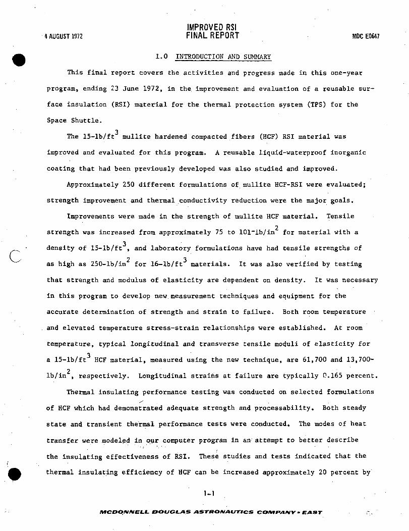
1.0 INTRODUCTION AND SUMMARY
This final report covers the activities and progress made in this one-year
program, ending 23 June 1972, in the improvement and evaluation of a reusable sur-
face insulation (RSI) material for the thermal protection system (IPS) for the
Space Shuttle.
The 15-lb/ft mullite hardened compacted fibers (HCF) RSI material was
improved and evaluated for this program. A reusable liquid-waterproof inorganic
coating that had been previously developed was also studied and improved.
Approximately 250 different formulations of mullite HCF-RSI were evaluated;
strength improvement and thermal conductivity reduction were the major goals.
Improvements were made in the strength of mullite HCF material. Tensile
2strength was increased from approximately 75 to 101~lb/in for material with a
3^_^ - density of 15-lb/ft , and laboratory formulations have had tensile strengths of
\ 2 3""" as high as 250-lb/in for 16-lb/ft materials. It was also verified by testing
that strength and modulus of elasticity are dependent on density. It was necessary
in this program to develop new measurement techniques and equipment for the
accurate determination of strength and strain to failure. Both room temperature
. and elevated temperature stress-strain relationships were established. At room
temperature, typical longitudinal and transverse tensile moduli of elasticity for
a 15-lb/ft HCF material, measured using the new technique, are 61,700 and 13,700-
2Ib/in , respectively. Longitudinal strains at failure are typically 0.165 percent.
Thermal insulating performance testing was conducted on selected formulations/ .
of HCF which had demonstrated adequate strength and processability. Both steady
state and transient thermal performance tests were conducted. The modes of heat
transfer were modeled in our computer program in an attempt to better describe
the insulating effectiveness of RSI. These studies and tests indicated that the
thermal insulating efficiency of HCF can be increased approximately 20 percent by
1-1
MCDOMNELL DOUGLAS ASTaOMAUTICS COHVf>AHY • EAST • -.,

IMPROVED RSI4 AUGUST 1972 FINAL REPORT MOCE0647
reducing the fiber diameter of about 20 percent of the fibers to below 2y diameter
and by reducing the fraction of filler (glassy spheres). A still lower thermal
conductivity would be expected if all of the fibers were below 2u diameter.
Improvements in material density and strength uniformity were constant goals
during this program. We concentrated first on density uniformity and then on
reducing the strength gradients in the material. Several cases were found where
the density gradients were near zero, but, surprisingly, the strength gradients
were severe: the weak areas were usually near the center of the HCF block. This
problem was alleviated by changing the processing: two organic materials were
added, the mixing procedure was improved, and the HCF felts were turned during
drying.
Processing and materials improvements, such as mixing and additives, have
resulted in a stronger and more uniform product. Binder solids control and wet
density control have both proven to be successful in improving the strength repro-
ducibility of HCF. Reimpregnation of fired felts with binder to improve the
strength was unsuccessful.
We have tightened controls on the incoming raw materials, and have improved
in-process and postprocessing controls in the fabrication of HCF. Two process
specifications have been prepared which define the process operations and control
parameters necessary for HCF fabrication and for the application of the inorganic
coating.
A summary of the designations of the major materials formulated and tested in
this program is given in Figure 1-1.
Reinforcement techniques (to hold the pieces together in case of separation
or delamination within the HCF material, and not as a strengthening device for the
HCF material), have been investigated. We have successfully processed reinforced
HCF tiles using ceramic yarn and metal wires in a 3-D array using the standard HCF
1-2
* j .
MCDONNELL DOUGLAS ASTRONAUTICS COMfAIW- EAST

4 AUGUST 1972IMPROVED RSIFINAL REPORT MDC E0647
c
MDAC-EASTDESIGNATION
MODI
MODI)
MOD III
MOD IDA
MOD IV
MODV
FORMULATION*
FIBERS
6(j MULLITE
6u MULLITE
4.7^ MULLITE
4.7 n MULUTE
2-5n MULLITE
4.7ti MULLITE+1.2(1 SILICA
FILLERS
ECCOSPHERES
CENOSPHERES
ECCOSPHERES
ECCOSPHERES
ECCOSPHERES
OPACIFIERS
ZIRCON
-
ZIRCON
ZIRCON
—
BINDER
RSB-2
RSB-2
RSB-2
RSB-2
RSB-2
RSB-2
OTHER**
-
—
-
HMT +CELLU-LOSE
HMT +CELLU-LOSE
HMT +CELLU-LOSE
COMMENTS
BASELINE MATERIAL
HIGHER MULLITEFRACTION INCOMPOSITION
UNIFORMITYUNACCEPTABLE
BASELINE SELECTEDAT END OF PROGRAM;VERY UNI FORM
DIFFICULT TO PROCESS;FIBERS NOT AVAILABLEIN QUANTITY
BEST THERMALPERFORMANCE;PROCESSING VARIABLESNOT YET DEFINED
C
*THE FORMULATIONS LISTED HERE ARE NOMINAL AND WERE VARIED DURING THE COURSE OF THIS PROGRAM.
** PROCESSING ADDITIVES WHICH DO NOT BECOME PART OF THE FINISHED PRODUCT BECAUSE THEYBURN OUT DURING FIRING CYCLE
MATERIALS DESIGNATIONS
FIGURE 1-1
felting process; no voids or cavities were found in the HCF tile, based on X-ray
and visual examination. An increase in density of 1.5-lb/ft resulted from the
use of a: columbium wire reinforcement. One sample of wire reinforced HCF was
tested to 2500°F without any sign of damage. This reinforcement effort led to the
concept of strengthening HCF by including metallic trusses in the HCF. When
metallic trusses are used in the HCF combined with the use of an efficient low-
density insulation, they could save up to 50 percent of the weight of an unrein-,^
forced RSI thermal protection system.
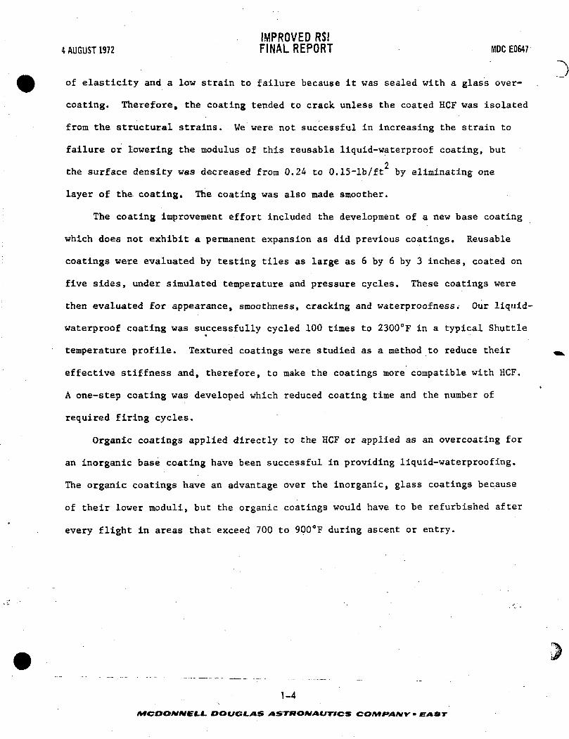
The reusable liquid-waterproof coating previously developed had a high modulus
1-3
DOUGLAS ASTRONAUTICS COMfANY • EAST
IMPROVED RSI4AUGUST1972 FINAL REPORT MDCE0647
of elasticity and a low strain to failure because it was sealed with a glass over-
coating. Therefore, the coating tended to crack unless the coated HCF was isolated
from the structural strains. We were not successful in increasing the strain to
failure or lowering the modulus of this reusable liquid-waterproof coating, but2
the surface density was decreased from 0.24 to 0.15-lb/ft by eliminating one
layer of the coating. The coating was also made smoother.
The coating improvement effort included the development of a new base coating
which does not exhibit a permanent expansion as did previous coatings. Reusable
coatings were evaluated by testing tiles as large as 6 by 6 by 3 inches, coated on
five sides, under simulated temperature and pressure cycles. These coatings were
then evaluated for appearance, smoothness, cracking and waterproofness. Our liquid-
waterproof coating was successfully cycled 100 times to 2300°F in a typical Shuttle*
temperature profile. Textured coatings were studied as a method to reduce their
effective stiffness and, therefore, to make the coatings more compatible with HCF.
A one-step coating was developed which reduced coating time and the number of
required firing cycles.
Organic coatings applied directly to the HCF or applied as an overcoating for
an inorganic base coating have been successful in providing liquid-waterproofing.
The organic coatings have an advantage over the inorganic, glass coatings because
of their lower moduli, but the organic coatings would have to be refurbished after
every flight in areas that exceed 700 to 900°F during ascent or entry.
1-4
/VfCOO/V/Vf C.C. DOUGLAS ASTRONAUTICS COH^fAtVV - EAST

IMPROVED RSI4 AUGUST 1972 FINAL REPORT MDCE0647
2.0 HCF DEVELOPMENT
The major goals of this program were to improve mullite HCF in the areas of
strength, thermal performance, uniformity in density and strength, and processabil-
ity. To accomplish these tasks we evaluated and selected raw materials, formulated
various compositions, and instituted and developed quality control procedures and
practices.
2.1 RAW MATERIALS - Mullite fibers of different diameters, various fillers
(hollow ceramic spheres), several inorganic binders, opacifiers, and several
organic processing aids were evaluated. Micrographic examination and other methods
were used to aid in the selection of the various materials. The materials were
classified as to appearance and dimensions both as received and after exposure to
several selected high temperatures.
Fibers - In addition to mullite fibers, which are currently available from
\_, Babcock and Wilcox (B&W) in a variety of fiber diameters, fine diameter silica
fibers were evaluated as a substitute for the hollow silica spheres (filler)
(Mod V).
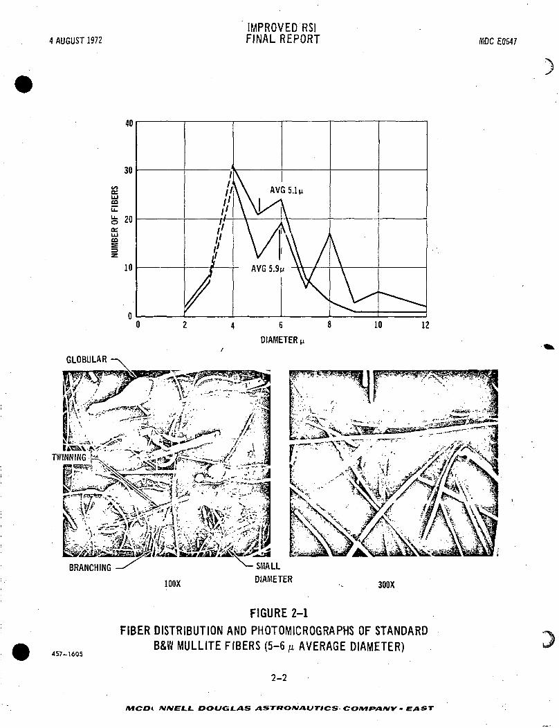
The mullite fiber grades which were investigated included:
0 Standard - 5 to 6-y average fiber diameter
0 Intermediate - 4.25 to 5.25-y average fiber diameter
0 Fine - 4.0-y average fiber diameter
0 Very fine - 2.5-y average fiber diameter
Figures 2-1, 2-2, 2-3, and 2-4 show the photomicrographs of representative
fiber specimens in conjunction with the distribution of fiber diameters for each
grade of fiber as supplied by the vendor. The differences between the standard,
intermediate and fine fibers seem to be due to the selective removal of the
coarser fibers, while the very fine (2.5-p diameter) fibers appear to be more
uniformly finer (more normally distributed fibers) than the other grades of fibers.
2-1
MCDONNELL DOUGLAS ASTRONAUTICS COMfA/VY - EAST ' ~
4 AUGUST 1972IMPROVED RSIFINAL REPORT IHDC E0547
GLOBULAR
TWINNING
4 6
DIAMETER,
100X
SMALLDIAMETER
300X
457-1605
FIGURE 2-1
FIBER DISTRIBUTION AND PHOTOMICROGRAPHS OF STANDARDB&W MULLITE FIBERS (5-6 M AVERAGE DIAMETER)
2-2
/VfCOi NNEL.L. DOUGLAS ASTRONAUTICS- COMPAIVY • EAST

4 AUGUST 1972IMPROVED RSIFINAL REPORT MDC E0647
cDIAMETER u
H%^?'l%||---M- j&ri -1 •#?•'?$!a tvT /'-'•.. :v'/ J/ 1tT'rtiira'' -<-"
K/:-'.:-'•''•-•? fer -^rf^Ug>£ 4- Wl^V*A. v-I 's , ,/» ?.ct
11
i^- «f- 3 .»>--• a ,-* > • / A'^'"lp*-'v
100X 300X
457-1004
FIGURE 2-2
FIBER DISTRIBUTION AND PHOTOMICROGRAPHS OF INTERMEDIATEB&W MULLITE FIBERS (4.25-5.25 AVERAGE DIAMETER)
2-3
MCDONNEL.L. DOUGLAS ASTt9O*/AUTICS COMPANY - EAST

4 AUGUST 1972IMPROVED RSIFINAL REPORT MDC EC647
4 6DIAMETER M
_: : . ^ V i* ^^ *• + "~
/^P^^f.f^ " .^^ ' »
457-1568
FIGURE 2-3FIBER DISTRIBUTION AND PHOTOMICROGRAPHS OF FINE B&W
MULLITE FJBERS (4.0 AVERAGE DIAMETER)
2-4
AfCDO/V/VE-L.L. DOUGLAS ASTttONAUTFICS COMPANY - EAST

4 AUGUST 1972IMPROVED RSIFINAL REPORT MDC E0647
C
;st WiS« vt, iF.-:"!..•>!.',': m %.; vvifi'A^'''-\ '^ " --Vn^
100 X
FIBER DIAMETER DISTRIBUTION:• 80% LESS THAN 4n• 65% LESS THAN 3n. 30% LESS THAN 2.5u• RIODE=2.5u
FIGURE 2-4
FIBER DIAMETER DISTRIBUTION AND PHOTOMICROGRAPHS OF VERY FINEB & W MULLITE FIBERS (2.5 ju DIAMETER)
300 X
c
Silica fibers, as shown in Figure 2-5, with an average fiber diameter of
1.2-y have a much softer texture than the coarser mullite fibers and are more
difficult to chop.
Fillers - Some of the inherent advantages and disadvantages of candidate
fillers for HCF are indicated in Figure 2-6. SI grade Eccospheres*, while light-
weight, sinter rapidly at 2500°F as shown in Figure 2-7. Although Cenospheres
sinter more slowly at 2500°F (See Figure 2-8), they are significantly heavier
than SI Eccospheres. , The "floaters," a fly ash product similar to Cenospheres
* Emerson & Cuming, Inc.2-5
AfOOO/V/VfLC. DOUGLAS ASTRONAUTICS COMfAIW • EAST

4 AUGUST 1972IMPROVED RSIFINAL REPORT MDC E0647
-fflSMlw ' ft aKjf* 54?"-- 5*' ^-tni^fe'lI' tCT'yJE^^*-^
s. J^ ' . /tfW^^ i i ' ^H^^
-iCi-** ' . feS^Wr ^ j'-'.iBSv*. SZZZsrtk £^S^A
300 X
FIGURE 2-5
PHOTOMICROGRAPHS OF SILICA FIBERS (1.2M AVERAGE DIAMETER)437-2537
2-6
XtST»O/V/»C/7-/CS CO/Vf^A/VK- EXIST

4 AUGUST 1972IMPROVED RSIFINAL REPORT MDC E0647
c
c
FILLER TYPE
COMPOSITION
PARTICLE SIZE(DIAMETER)
BULK DENSITY
PARTICLE DENSITY
SINTERINGTEMPERATURE
SI ECCOSPHERES
Si02~90%
30 TO 125u
11 PCF
16 PCF
~2300°F
LOW P CENOSPHERES
Si02~ 60%
A1203 ~ 30%
50T0150u
17 PCF
22 PCF
~2500°F
"FLOATERS" *
Si02~53%
A1203~ 33%
40 TO 180M
28 PCF
37 PCF
~2500°F
FA-A ECCOSPHERES
NOT AVAILABLE
60 TO 325M
25 PCF
35 PCF
1800°F
437-2340
*A FLY ASH COMPONENT FROM LOCAL ELECTRICITY GENERATING STATION OF UNION ELECTRIC CO.
FIGURE 2-6
PROPERTIES OF CANDIDATE FILLERS
but from a local power plant, were much denser than the Cenospheres.
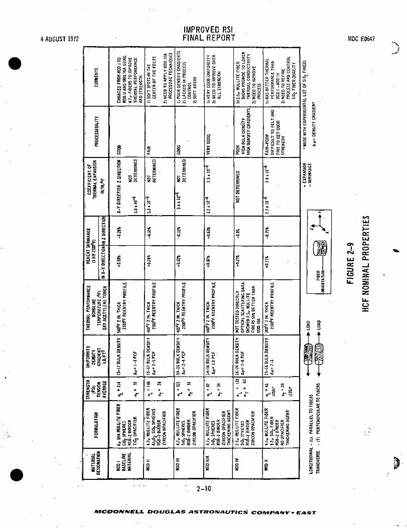
2.2 FORMULATION AND PROCESSING - Five new general mullite HCF compositions«
were formulated and their properties were evaluated relative to Mod I HCF, our
baseline HCF at the beginning of this period. Figure 2-9 shows the basic proper-
ties of Mod I and the properties of the newer HCF materials. The new HCF insulations
were tested for strength, impact indentation, uniformity, density, processability,
and thermal performance. Specimens of 3.3-inch diameter were formed to determine
the initial fabrication parameters for each new HCF composition. Factors which
were controlled included blending time, binder specific gravity, slurry viscosity,
drain time, batch size, height and weight of the felt, drying cycle and firing
cycle. Initial strength and density gradient data were obtained from the 3.3-inch
diameter specimens. The felting and testing procedures were later scaled up to
9 and 11-inch diameter specimens. The most promising HCF compositions (Mod IIIA
and Mod V) were scaled up to 14 by 16 by 4-1/2-inch specimens. Mechanical
2-7
DOUGLAS ASTRONAUTICS COMf»A*IY • EAST

4 AUGUST 1972IMPROVED RSIFINAL REPORT MDC E0647
i';TN^T-
|, P~
K'- Sii
, ' . - - . i t • '- -vj-^\^*' d* V&A,-V>Vr^>.^r^3a
^•Kir-y^*»^,.ft1
*' - *-*I P^ • --v --^ X rt ' ' ' ' I*- ^ * ' "'• >r._>'-* --*:• •V-A, ' - . , - .- \a&"* '^?\- £f ' -• F:*\ " -' F%& *^3^-V^ \.-- !T *v...^-rv -, v-^^J
-•«<.;; T--r-VSgf . ^.-;, '.-^ : ' / ' >~~<* " ' '.'. s-' V^"^f^^
SI ECCOSPHERES AS RECEIVED
457-1271 100 X
j>^^SS^>---:>^.^*^;-j^^ ;-' ^S,-k e*--'-"- -x^r',-.-- ' . - • , - . - "/ * T 5 ^ ' - - - . V / * - T »l";C^ fe- ••• - .#- • - - -, - ":, .-,?5?L' \ ,-J?^t ' ^
K-;^?^^--' ; B|/ "- ^g/^?^/ '-^^^ ':1J->^W*.fer :<v--:;-;:/^i^^
SI ECCOSPHERES FIRED AT457-1272 2500°F FOR 1 HOUR
100 X
FIGURE 2-7—-—— . - - • • - 2 _ 8
MCDONNELL. DOUGLAS ASTRONAUTICS COMPANY • EAST

4 AUGUST 1972IMPROVED RSIFINAL REPORT MDC E0647
G
c
l»-:2t4» mm <t&» JkaA. r*~i 4w/m*
457-,273
LOW DENSITY CENOSPHERES
AS RECEIVED
100 X
' ' '
^ ;-^P¥^f^ 0^v^P^SB •^^^^^Q- ' ^^li--.-/' ,>asa*«~BS* <» C'j^hkC-is- -,a _fisi.j*iA.-nrf-MrW'"V^>^2*8®^ fc '«^-?;.. -^A5«g
^M^J^Sfe^iMiSl
457-1274 LOW DENSITY CENOSPHERES
AFTER FIRING AT 2500°F FOR 15 MINUTES
100 xFIGURE 2-8
2-9
MCDOfHtVELL. DOUGLAS ASTKOMAUTICS CO/VifAMY • EAST
4 AUGUST 1972IMPROVED RSIFINAL REPORT MDC E0647
COM
MEN
TS
^"' 2
CO
' UJuo
fei(_ g
. UJ X
y.UJ **•u, S z7
; ui s • ; S£ £; ^^ -
*~
: °CJ
. uj, UJca or3C °
•oc u7 z
£i g
:l= §
^
o 55 u7£S o °
g UJ UJ uj
as J 2' UJ
;:P||:|. "i
i E.^ 5*»—
; o S s t'z Q§ ™
f. X"1
f. M ^ IV-
UJ Z uj
v>
; g
! 3 "
£
sia
r
HANG
ED F
ROM
MOD
1 T
O00
II A
ND
MO
D II
IA U
SINI
7u F
IBER
S TO
IMPR
OVE
HERM
AL P
ERFO
RMAN
CEND
STR
ENG
TH
CJ S * S- «
3O
Z °o uj
CJ . S
O O UJNJ Z 0
as-of=«JUJ IO
— 0
H 3
i1
iCD+•
UJ_Ju-
£
^ ^ .y »-
— u.
£§5
*-"£UJ0 u.
3 0-
CD 1
I 4-
«« m
a u
i-acUJCOu_uj ec
T « S -_J 1.1 UJ \f
= * z "
iflrUJ ^
' j S™ QJ UJat / i t—
_ «s
SOFT
SPO
TS IN
THE
CENT
ER O
F TH
E FE
LTS
NEED
TO
APPL
Y M
OO 1
1PR
OCES
SING
TEC
HNIQ
U
- cs.
ce
u.
oUJ
oz .
O UJac a
^M
CO
soi
+
UJ
iZo£
y *~
z or
% is?
t
UJa u.
5 of
r^ ****
i^-
« °^ii u
<r „g £ \a
t||§* <-T^ °^s'is
ai
P
POOR
DEN
SITY
GRA
DIEI
LAC
KED
IN P
ROCE
SSCO
NTRO
LS
On
AREA
S
- ~ "
a|
aUJ
alUJ
^ v~z o
1~T
11
1+1
UJ.Ju_gG_
^ trO H-
Z K
— u.
§; §^
^UJ
0 u.
5 a-CD 1
Z <
II II
o-1 f
ac.
u. ii
t||<
2 ;fi S
_ai
>• K
VERY
GO
OD
UNIF
ORM
ITNE
ED T
O I
MPR
OVE
OVE
ALL
STRE
NGTH
— <-g
a
UI
2
f\
T>
s
s•?
so+•
* :oz
— u.cst ii
fe §5
^UJ° u.-J a.
2 °
ii
it nD-1 J"
o.
u. EZ o
=liii^"ola
!|
£>•
2.5 M
MU
LLIT
E F
IBER
SHOW
S PR
OM
ISE
TO L
OWTH
ERM
AL C
ON
OU
CTW
nNE
ED T
O I
MPR
OVE
PROC
ESS
- ~
J.t gs °Q t
111
oLUZ
UJ
UJo
g
se>
s.a
<
2|uj|
uj £ d st E
i-P,K P g g g
z o 5 ii £
t—
UJ0 u.
5 S
f "<SJ ||
U II
_1 t-O 0
£00 £
u- u.
¥ uj £ ^
t-0 irt ae M
^oi
HAS
BETT
ER T
HERM
ALPE
RFO
RMAN
CE T
HAN
MO
D 1
. M
OD
IV
NEED
TO
REF
INE
PROC
ESS
AND
CONT
ROL
Si0 2
FIB
ER Q
UAL
ITY
-* csi
0z^_
UJ Ou. o
a: . ujO j O ^C
u. a u7 S
0
fvj
t,
ctj
g
=7*
*»
•*•
UJ_ju,o
°x: or
z— u.
^ §s
»—
2UJa
_jCD 1
5^-
3 ._ S ,_
S i-e SU. CC uuj "J oc ee *t
5 ^ l.gMa a i o o
i— tv <s* O Z^ « a: z t-
§
L LO
T O
F Si
0 2 F
IBER
S
h-
UJO
u££UJo
I <
X UJo o
i5« si E
ss4. 1
>•t •
-^xAffil1 jjijy
1SP
SorO
0 0
1 3
11
Si] U l lE 9 fe^l
C^ 03,, |
UJCO
0 U_
£5 o00 ^
IJuj a-J Z-J UJ
S o.CC
«t UJa. a.
5 £
z uj
z g-1 h-
OC.UJ
<n 0.i oCM a;
Hi CLOS. _J=3 «£CS z
O
2-10
MCDOIVIVELL DOUGLAS ASTttOnJAUTICS COMPANY* EAST

IMPROVED RSI4 AUGUST 1972 FINAL REPORT MDCEOH7
properties testing and coating development were conducted using the. larger HCF
specimens (9-inch diameter or 14 by 16-inch sizes).
Mod II HCF - Mod II HCF was formulated as a totally mullite reusable surface
insulation. Initially, Mod II consisted of 6.0-y mullite fibers, mullite binder
and aluminosilicate glass spheres. Several 3.3 and 9.0-inch diameter all-mullite
specimens were processed. X-ray diffraction studies showed the Mod II to be gamma
Al-0. and mullite. No silica (cristobalite) was detected. The strength of the
Mod II with mullite binder was low. An evaluation of slurry viscosities, blending
procedures, and firing cycles indicated that the strength properties desired could
not be obtained with this all-mullite system. A silica binder, RSB-2, that had
been used successfully with Mod I HCF to improve its strength was tried. Strength
values did increase substantially when the new binder was used. With the addition
of the silica, X-ray diffraction showed some cristobalite formation after firing.
At the same time, we began using 4.7-y diameter mullite fibers. The 4.7-u mullite
fibers seemed to improve the thermal performance during early screening tests.
The altered Mod II consisted of 4.7-y mullite fibers, aluminosilicate spheres,
RSB-2 binder, and zircon opacifier. The only compositional change from the Mod I
material was the substitution of aluminosilicate glass spheres for the silica
spheres. Two types of aluminosilicate glass spheres were tested. The first was a
fly ash derivative from a local source (Union Electric "Floaters"). The second
was fly ash spheres from England (Cenospheres). The Cenospheres had a higher
degradation temperature than the SiO™ spheres due to the greater wall thickness
and the composition of the Cenospheres (see Section 2.1).
Mod II specimens were produced in two diameters, 3.3 and 9.0-inches. The
Mod II felts processed much differently than the Mod I; i.e., nearly every Mod II
felt retained excessive binder on the top and bottom surface, causing a soft
center problem. Photomicrographs clearly showed the lack of binder in the center
2-11
MCDONNELL DOUGLAS ASTRONAUTICS COIMfANY' - EAOT "

IMPROVED RSI4 AUGUST 1972 FINAL REPORT MDCE0547
of the Mod II specimen. Figure 2-10 shows a typical density gradient, through a
sample of Mod II. We believe the binder deficiency was caused by a binder, fiber,
Cenosphere wetting phenomenon, and binder migration during drying. To correct
the soft center problem in Mod II, we varied the slurry viscosity and the solids
content in the binder. The results of these studies showed that an increase in
blending time decreased the slurry viscosity and increased the bulk density of the
Mod II specimen. The soft center condition was partially controlled by longer
blending times, but many Mod II felts were unacceptably dense (16-18 Ib/ft ).
Work on Mod II was suspended because it did not appear that an acceptable product
could be made using this formulation.
Mod III HCF - Mod III was the next series of HCF materials formulated, and it
consisted of 4.7-y diameter mullite fibers, SiCL spheres, RSB-2 silica binder and
zircon opacifier. Mod III processed easily but the uniformity of the material and
the reproducibility of the process were erratic as shown in Figure 2-11. The most
serious problems with Mod III were the densified surfaces and the soft centers of
many felts.
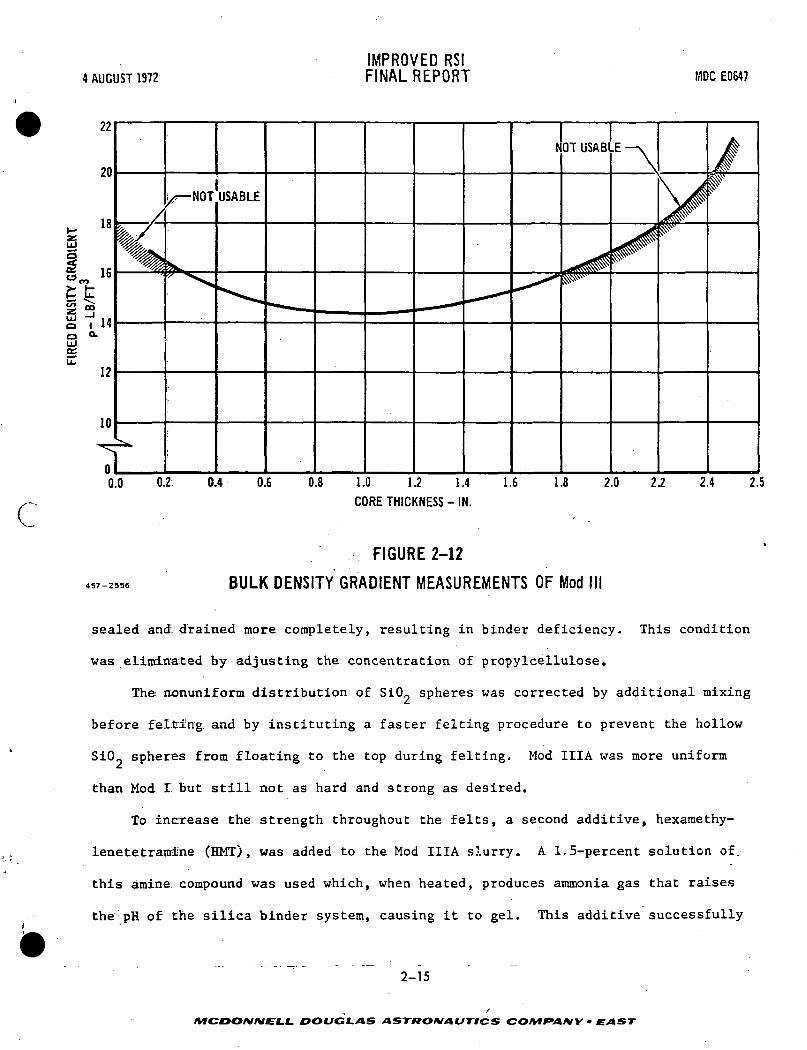
We processed Mod III HCF to obtain felts which had 15 + 1.5-lb/ft bulk fired
density with a minimum density gradient through and across the specimen. Figure
2-12 shows typical gradients encountered in a typical Mod III felt. We also
noticed the tendency of coated Mod III blocks to fail during reentry simulation due
to delamination cracks in the X-Y plane. Many of the cracks occurred through the
soft center portion of the Mod III tiles.
Mod IIIA HCF - Mod IIIA has the same composition after firing as Mod III. The
basic change was the use of additives (processing aids) to make fabrication of
Mod IIIA easier and to improve the uniformity of the HCF. The first additive tested
was propylcellulose . When added in small quantities (less than 0.2 percent by
Prbpylcellulose - Klucel, Hercules Corp.
2-12
~>
i_l_ DOUGLAS A&T99OMAUTICS COMf»AMY - EAST "'•

4 AUGUST 1972IMPROVED RSIFINAL REPORT MDC ECS47
c
20
18
17
16
LUo
15
14
\ HARDCRUST
SOFT CENTERWITH LOWER DENSITY
HARDCRUST
0.2 0.4 0.6 0.8 1.0 1.2 1.4
THICKNESS - IN.
487-2537
FIGURE 2-10
DENSITY GRADIENT OF MOD II HCF
2-13
1.6 1.8 2.0 2.2 2.4
MCDOIMMELt- DOUGLAS ASTftOMAiJTICS COMfA/VV • EAST

4 AUGUST 1972IMPROVED RSIFINAL REPORT MDC E0647
18
17I/CO
t
_J
1
ui 16ooUJccu.
_lCO
1C13
;
o J
o
o
f
)
oo
(o
o
)
<
o
o
o
) O
o oc
-
o
o u>
o
265 270 275 280
FELT NUMBER SEQUENCE
285 290
437-2578;
FIGURE 2-11
PROCESS VARIABILITY OF MOD III WITH NO PROCESSING AIDS
weight of: binder), the cellulose decreased the felting and drain time and drastically
reduced the density gradient through and across the Mod IIIA specimens. In con-
centrations greater than 0.2 weight percent, the cellulose additive thickens and
foams the slurry. Figure 2-13 shows the improved uniformity in Mod IIIA compared
to Mod III.. The cellulose additive did not correct the soft centers even though
the density of the Mod IIIA was extremely uniform and the final fired densities
became controllable. Photomicrographs showed two conditions which caused soft
spots. One was less binder in the central portion of the felt, the other was
silica sphere migration. It was found that the 4.7-p fibers pulled away from the
felting column as soon as the felt formed, preventing adequate drainage around the
edge of the specimen due to air leakage. The center of the specimen was still well
. - - - - - : - - 2-14 - - • - - •
MCDONNELL DOUGLAS ASTRONAUTICS COIVtrANY ~ EAST
c
4 AUGUST 1972IMPROVED RSIFINAL REPORT MDC E0647
oLJ
22
20
18
16
14
12
10
-NOT USABLE
NOT USABLE •
0.0 0.2 0.4 0.6 0.8 1.0 1.2 1.4CORE THICKNESS - IN.
1.6 1.8 2.0 2.2 2.4 2.5
457-2536
FIGURE 2-12
BULK DENSITY GRADIENT MEASUREMENTS OF Mod
sealed and:. drained more completely, resulting in binder deficiency. This condition
was eliminated by adjusting the concentration of propylcellulose.
The nonuniform distribution of SiO~ spheres was corrected by additional mixing
before fel.ti'ng and by instituting a faster felting procedure to prevent the hollow
SiO? spheres from floating to the top during felting. Mod IIIA was more uniform
than Mod I but still not as hard and strong as desired.
To increase the strength throughout the felts, a second additive, hexamethy-
lenetetramine (HMT), was added to the Mod IIIA slurry. A 1.5-percent solution of.
this amine: compound was used which, when heated, produces ammonia gas that raises
the pH of the silica binder system, causing it to gel. This additive successfully
2-15
MCDONNELL DOUGLAS ASTRONAUTICS COMfANY • EAST

4 AUGUST 1972IMPROVED RSIFINAL REPORT YDC E0647
Iin
ri. Si
^
=303
j.U/81-d
UJ .oc oo zo
2-16
MCDONNELL DOUGLAS ASTRONAUTICS COMPANY • EAST

IMPROVED RSI4 AUGUST 1972 FINAL REPORT MDC E0647
f
set the binder, but it did not totally eliminate the strength gradients through
larger (14 by 16 by 4.5-inch) HCF felts. The edges of the felts were consistently
stronger than the centers, even when the density was uniform. Bind°.r migration is
believed to have caused this for three reasons:
1. transporting of binder solids caused by drying at the surfaces
2. excessive draining in certain areas caused by location of drain holes
in the felting apparatus
3. settling to one side caused by gravity prior to curing.
The binder migration was significantly reduced, but not completely eliminated
by adding the hexamethylenetetramine (HMT).
Figure 2-14 shows the effects of temperature and HMT concentration on gel
time. The circled points are actual data; the remainders of the curves are-E
extrapolations based upon Arrhenius1 theory K = Ae "KT. In the temperature range
used (140 to 190°F), the time to gel is rather short, ranging from 3 to 13 minutes.
An in-process control which eliminated excessive draining was the weighing of
the felt during the vacuum drain portion of the felt forming operation. The wet
weight, monitored during the drain period, was used as a measure of the amount of
the binder left in the felt. When a predetermined wet weight was reached, the
vacuum pumping was discontinued, stopping the flow of liquid binder from the felt.
A series of 154 felts was made using this additional control; a significant improve-
ment in HCF strength, and a narrowing of the strength scatter band resulted. The
continual monitoring of the wet weight of all felts during production has improved
the reproducibility of the processing.
Manufacturing facilities for Mod IIIA have been scaled up, and many 14 by 16
by 4-1/2-inch tiles have been produced for coating evaluation and basic property
testing. Mod IIIA has finer texture and is easier to coat than Mod III. The
addition of the cellulose thickener allows longer blending times and permits drain-
2-17
MCDOHMELL DOUGLAS ASTftOMAUTICS COIVir'AMY - EAST

IMPROVED RSIFINAL REPORT
ACTUAL DATAPOINTS ARECIRCLED.
CURVES AREDERIVED FROMTHESE POINTS
MDC E0647
457-Z448
170
TEMPERATURE (°F)
FIGURE 2-14REACTION RATE OF HMT AND COLLOIDAL SILICA BINDER
K= Ae
WHERE
-E
RT
K =A =
e =E=R =T =
ARRHENIUS' RATE EQUATION
SPECIFIC REACTION RATE (SEC'1)NUMBER OF MOLECULES COLLIDING PERGRAM MOLECULAR WEIGHT PER SECOND2.718ACTIVATION ENERGY (CAL/GM.MOL. WT.)GAS CONSTANT (CAL./GM.MOL.feT.-0K)ABSOLUTE TEMPERATURE (°K)
2-18
/MCOO/V/VEf-l. DOUGLAS ASTftOfHAUTICS COM F»AIW - E AST

IMPROVED RSI4 AUGUST 1972 FINAL REPORT MDCE0647
ing of excess binder.
Mod IV HCF - Mod IV HCF consisted of 2.5-y mullite fibers, SiCL spheres, and
RSB-2 binder. Its strength was nearly the same as Mod III, but its calculated
thermal performance was better. Actual thermal performance was determined from
optical scattering data and oxyacetylene torch tests. The finer fiber mullite was
much more difficult to process than the fiber used for Mod IIIA HCF. The use of
additives (propylcellulose and HMT) hindered binder drainage.
Work on Mod IV HCF was suspended because a sufficient quantity of the 2.5-y
mullite fiber was not available during the contract period. More work is needed
to determine the full potential of Mod IV HCF.
Mod V HCF - Mod V was pursued to improve the thermal performance of HCF
insulation. All of the HCFs (Mod II, Mod III, Mod IIIA and Mod IV) had a spherical
hollow glassy filler as part of their formulation. By substituting the very small
C diameter silica fiber for the glassy spheres, a reduction in radiant heat transfer
seemed likely. The basic formulation of Mod V was set at 80-percent mullite fibers
and 20-percent SiO~ fibers by weight. Because the SiO™ may devitrify and undergo
disruptive volume change upon heating and cooling, an upper limit of 25 weight
percent was set for experimentation. Mod V was fired at 2300°F.
The texture of Mod V was superior to any other HCF composition tested, and
it was also easily coated. Mod V had thermal performance superior.to the other
HCFs. (See Section 3.3.) This is due to the increased heat radiation scattering
caused by the 1.2-y Si02 fibers. An HCF composed entirely of SiO~ fiber HCF had
somewhat lower thermal conductivity than Mod V, but an all-SiO_ HCF exhibited con-
siderable shrinkage and some cracking when heated to 2500°F. The mixture of mul-
lite and SiO? fibers seems to produce both good thermal performance and good
physical stability.s •/ L
The microstructure of Mod V is much more compact than any previous HCF. This
2-19
MCDONNELL DOUGLAS ASTRONAUTICS COI*if»A*IY - CAST

IMPROVED RSI4 AUGUST 1972 FINAL REPORT MDC E0647
compactness required long felting and drain times and mechanical pressing of the
fibers. Figure 2-15 shows a density profile through a Mod V specimen and the
effect of pressing. The Mod V felts were very difficult to remove from the felting
apparatus. During felting, the Mod V would pull away from the column walls. This
sealing problem was solved by pouring mixed slurry into the gap between the wet
felt and felting column immediately after felting. Resealing the Mod V felts
allowed proper binder drainage. The problem of removing the Mod V felt from the
column without damage was accomplished by lining the felting apparatus with a
removable liner and mechanically forcing the felt backward out of the felting
column.
Another processing procedure which affected the compounding of Mod V was the
propylcellulose. On all other HCF compositions, the cellulose additive was added
to and mixed with the entire slurry batch. In processing Mod V, the cellulose
thickener and HMT processing aids were dissolved in water and-then added to the
binder. The dissolved additives were discovered to be much more active when they
were dissolved prior to use. Mod V, however, because it was a totally fibrous
system, had to be mixed longer than other HCF compositions. The energy imparted
by the mixer during longer mixing heated the slurry to over 120°F. The cellulose
material had higher solubilities when cool, so the binder was cooled to 40°F before
processing. Figure 2-16 shows the temperature rise of the binder during.mixing
Mod V.
The most important processing step during manufacturing Mod V was the firing
cycle. Once Mod V is properly fired, it is very stable through coating processing
and reentry simulation cycling. Mod V, however, is sensitive to the initial firing
cycle and a quick firing cycle appears to be best overall. Mod V HCF has good
potential as a reusable surface insulation. Specimens up to 16 by 14 by 4-1/2
inches have been fabricated and tested. When properly formed and fired, the
2-20
MCDONNELL DOUGLAS ASTRONAUTICS COMPANY - EAST

4 AUGUST 1972
c
• /"
IMPROVED RSIFINAL REPORT
DMOD V SPECIMEN PRESSED FROMTOP OF FELT DURING DRAINING
MDC E0647
AS FELTEDNOT PRESSED
0 0.2 0.4 0.6
BOTTOM OF FELT
0.8 1.0 1.2 1.4 1.6 1.8 2.0 2.2 ' 2.4
TOP OF FELT
THICKNESS - IN.
457-2M8 FIGURE 2-15
TYPICAL DENSITY GRADIENT THROUGH MOD V HCF SHOWING
THE EFFECT OF MECHANICAL PRESSING DURING FABRICATION
thermal shock resistance and strength of processed Mod V was equal to that of
Mod IIIA. However, a major difficulty with Mod V was establishing an acceptable
initial firing cycle due to the batch-to-batch variation in the heat stability of
the SiO fibers. The prior processing history of the SiCL fibers was the major
remaining problem preventing production of good quality Mod V in quantity.
Opacifiers - Many HCF specimens were formulated, fabricated and evaluated to
improve the thermal performance of HCF by reducing radiant heat transfer, as
shown in Figure 2-17. Oxides such as Cr, , Go^ and NiO colored the HCF: Cr2°
2-21
MCDO/VMELL DOUGLAS ASTRONAUTICS CO/VI#WV>- » EAST

4 AUGUST 1972IMPROVED RSIFINAL REPORT MDC E0647
CELLULOSE THICKENER HARDENS HCF AT 110°F ALMOST INSTANTLY
ceLUo_
BINDER UNSTABLE (32°F)
•HS-
3 4
TIME (MINUTES)
LS—| HS-
NOTE: LS - LOW SPEED ON HOBART 80HS-HIGH SPEED ON HOBART 80
437-2360
FIGURE 2-16SLURRY TEMPERATURE INCREASES WITH MIXING TIME IN HOBART 80 MIXER
(green), Co_0, (blue) and NiO (black), and all caused some local fluxing of the
HCF and increased its strength. Cr2°3»
c°3°4» and Ni° very likely increased the
emittance' of the mullite fibers but also increased the heat transfer through the
HCF slightly. The best ceramic opacifiers were TiO_ and ZrSiO^. Both Ti02 and
ZrSiO, are white, have a high refractive index (scatter heat radiation well), and
are thermally stable in the HCF composition. One, three and ten percent additions
by weight were added to the baseline Mod IIIA composition and evaluated for thermal
performance in 3.3-inch diameter "hockey puck" tests (see Section 3.3). In these
evaluations the maximum surface temperature of the specimens was 2300°F and the
time as a function of backface temperature was recorded. The best results were
obtained using 3-percent by weight ZrSiO, (zircon) opacifier. (In comparison to
basic Mod IIIA, the opacifiers had relatively little effect on thermal performance.)
The second method of opacification was to vary the fiber diameter. Studies
2-22
MCDONNELL DOUGLAS ASTRONAUTICS COIVIfAHY-EAST

4 AUGUST 1972
IMPROVED RSIFINAL REPORT MDC E0547
c
OO
CC
1ou
TYIV
IS T
TI NSE M
CO
ND
UC
SP
EC
IME
DIA
(9
o <"t— in
_ 31
£3=i£ 2 ^P£ Eo . u.
—i 1112 o> zLU <CCC 3CQ. U
S SCM CM
I ceCO LUs =oSU CL.O O
•V ~il2
ui uia. -J
h- UJ
= ?
si§5
•n
OoLU
o u o ce
O CM CM CM CM CM CMCp e o o o o o o o o o , o o
0 -
[-0 ,^
^ s: s«:O 0 0
C^C^O** 3 3' C ^ ' 0 0 0 0 0 0
CM CM CM000
o CM csj c^
457-2330
; r FIGURE 2-17HCF COMPOSITIONS CONTAINING OPACIFIERS
2-23
DOUGLAS ASTKOMAUTICS COntf»AfVy - EAST

IMPROVED RSI4 AUGUST 1972 FINAL REPORT MDC E00.47
(Reference a) showed that thermal performance improved (lower thermal conductivity)
as the fiber diameter decreased. Mullite fibers of 2.5, 4.7 and 6.0-u diameters
were evaluated for thermal performance by optical scattering measurements. The
2.5-u mullite fibers were the most promising fibers of the group and were used to
make several Mod IV felts. However, no thermal conductivity tests were run on
Mod IV (2.5-y diameter fibers) because not enough fibers were available to fabricate
specimens.
Because of availability, small fiber diameter, and a composition somewhat
similar to mullite, we evaluated SKX Fiberfrax* (2.5-u aluminosilicate fiber) mixed
with 4.7-y mullite fibers. From a radiation scattering standpoint, the SKX fibers
were found to be approximately equal to the Si02 fibers (reference a). However,
the SKX fibers were harder to process and did not survive thermal cycling as well
as Si02 fibers'. We also evaluated a 1.2-y mullite type fiber, Fiberfrax HT^, which
was extremely hard to process and the resultant HCF specimens were very weak. The
HT fiber contained fiberized material and it was judged unsuitable for producing
HCF.
Of all the fibers additions evaluated, the 1.2-y SiO~ fibers (Microquartz)
were the most effective radiation scatterer. The Mod V HCF contained 20-percent
SiCL fiber substituted for the SiCL spheres and was discussed previously.
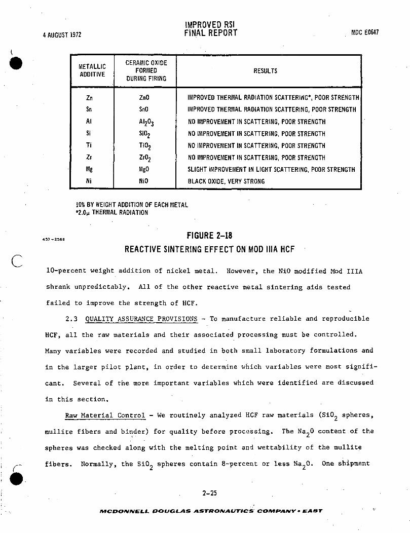
Reaction Sintering - The opacification studies indicated that the strength of
HCF might be improved by using reactive metal additives. By adding a selected
metal to the HCF a desired ceramic oxide might be formed in place within the
insulation during the firing cycle. This oxide then would react with the ceramic
fibers and filler as the block is fired and it would affect the strength. Certain
oxidized metals slightly inqjroved the radiation scattering of the Mod IIIA material
2(see Figure 2-18). Strengths of over 200-lb/in in tension were obtained with a
* Experimental Fiber - Carborundum Co.
t Carborundum Co.2-24
/VTC0O/V/V£-J.£, DOUGLAS ASTttONAUTICS COMPANY • EAST
4 AUGUST 1972
IMPROVED RSIFINAL REPORT MDC E0647
c
METALLICADDITIVE
Zn
Sn
Al
Si
Ti
Zr
Mg
Ni
CERAMIC OXIDEFORMED
DURING FIRING
ZnO
SnO
AI203
Si02
Ti02
Zr02
MgO
NiO
RESULTS
IMPROVED THERMAL RADIATION SCATTERING*, POOR STRENGTH
IMPROVED THERMAL RADIATION SCATTERING, POOR STRENGTH
NO IMPROVEMENT IN SCATTERING, POOR STRENGTH
NO IMPROVEMENT IN SCATTERING, POOR STRENGTH
NO IMPROVEMENT IN SCATTERING, POOR STRENGTH
NO IMPROVEMENT IN SCATTERING, POOR STRENGTH
SLIGHT IMPROVEMENT IN LIGHT SCATTERING, POOR STRENGTH
BLACK OXIDE, VERY STRONG
10% BY WEIGHT ADDITION OF EACH METAL*2.0M THERMAL RADIATION
457-2568 FIGURE 2-18
REACTIVE SINTERING EFFECT ON MOD MIA HCF
10-percent weight addition of nickel metal. However, the NiO modified Mod IIIA
shrank unpredictably. All of the other reactive metal sintering aids tested
failed to improve the strength of HCF.
2.3 QUALITY ASSURANCE PROVISIONS - To manufacture reliable and reproducible
HCF, all the raw materials and their associated processing must be controlled.
Many variables were recorded and studied in both small laboratory formulations and
in the larger pilot plant, in order to determine which variables were most signifi-
cant. Several of the more important variables which were identified are discussed
in this section.
Raw Material Control - We routinely analyzed HCF raw materials (SiO- spheres,
mullite fibers and binder) for quality before processing. The Na-O content of the
spheres was checked along with the melting point and wettability of the mullite
fibers. Normally, the SiCL spheres contain 8-percent or less Na_0. One shipment
2-25
MCDONNELL. DOUGLAS ASTRONAUTICS COMF>ANY • EAST

IMPROVED RSI4 AUGUST 1972 FINAL REPORT MDCE0647
of SiO™ spheres was rejected because of high Na~0 content.
Quantitative analysis was performed by atomic absorption spectrophotometry
after dissolving each specimen using the Bedrick Bernas method.* The test results
for various fibers follows. All values are reported in weight percent of the
oxide and the silica content was obtained by difference.
//I Early #2 Intermediate #3 Contami- /M LocalBatch - SI Batch - SI nated Batch Spheres (UnionEccospheres Eccospheres Eccospheres Electric)
Aluminum (Al-O,)
Lithium (Li20)
Potassium (K.O)
Sodium (Na20)
Iron (Fe203)
Magnesium (MgO)
Calcium (CaO)
Silicon (Si02)
The variation of sodium (Na.O) content is apparent between Eccosphere batches
and especially in the contaminated material (material contaminated during processing
by Emerson and Cuming). The local fly ash taken from the Union Electric material
has a high alumina (Al,,0_) content as expected.
The "as processed" Mod II HCF was also analyzed by the same process as the
Eccospheres and the test results are given as follows:
Samples
Standard #122
Aluminum (Al ) 32.9 35.9
Lithium (Li20) < 0.01 < 0.01 >
Potassium (K20) < 0.06 < 0.06
* Bernas, Bedrick, Anal. Chem. 40, 1682, October 1969.2-26
DOUGLAS ASTRONAUTICS COMfANY • EAST
0.08
0.02
0.03
8.1
0.04
0.03
0.04
91.7
0.11
0.02
0.03
12.4
0.05
0.12
0.04
87.2
0.10
0.02
0.02
15.4
0.05
0.09
0.04
84.4
32.6
0.04
4.05
4.1
5.1
0.90
0.42
52.8

IMPROVED RSI4 AUGUST 1972 FINAL REPORT MDCE0647
Sodium (Na20) 2.47 2.10
Iron. (Fe20 ) 0.05 0.07
Magnesium (MgO) 0.23 0.20
Calcium (CaO) < 0.01 < 0.01
Titanium (Ti02> < 0.02 0.53
Silicon (Si02) 64.3 61.1
NOTE: Percent silicon calculated by difference.
The. .specif ic gravity and solids content of the silica binder were monitored.
These two properties help control the final density and strength of the HCF. For
a given HCF formulation, the final density of the material can be predictably
raised or lowered. The binder is generally diluted to a fixed specific gravity
before processing. Specific gravity is adjusted by adding deionized water or
fresh binder as necessary. Figure 2-19 shows the relationship between specific
c gravity and solids content. In spite of the replenishment, the binder can only be
1 reused once before it becomes deficient in silica and degrades the strength of the
product.
Analyses have been run on samples of binder which had been used various
numbers of times. The results of these analyses are shown in Figure 2-20. The
solids remained constant but the silica (SiO?) containing binder phase was removed
with reuse. Figure 2-21 shows the binder analysis when cellulose thickener is
added to the RSB-2 binder. Again silica was depleted with reuse.
During the felting process, the opacifiers (Ti02 or ZrSiO.) collected in the
binder. The analysis of binder for the TiO opacifier in Mod I is shown below:
Fresh Binder • 1 Reuse
Magnesium (MgO) 0.23 0.20
Calcium (CaO) <0.01 <0.01
Titanium (Ti02) <0.02 0.53
"S i l i c o n (Si02) ' " 64.3 " 61.12-27
MCDONNELL. DOUGLAS ASTKOKIAUTICS COMfVUVV • EAST

4 AUGUST 1972IMPROVED RSIFINAL REPORT MDC EOS47
1^4
1.22
UO
1.18
1.16
>- 1.14
I U2o
5J 1-wfe
1.08
1.06
1.04
1.02
1.00 XXS~
_*
XX
Xr
xX
X^Xr
\
\
>*
o
Xw<ftX
cX
X
] 2 4 6 8 10 12 14 16 18 20 22 24 26 28 3(
SOLIDS - PERCENT BY WEIGHT
NOTE: BINDER AS RECEIVED-30% SCLIDS/1.23 SG
457-2447
FIGURE 2-19
SPECIFIC GRAVITY OF COLLOIDAL SILICA BINDER AS A FUNCTION OF SOLIDS CONTENT
Three percent by weight TiCL was added to the slurry before felting. The
standard material had no opacifier added. Specimen #122 (Mod I) retained only
about 18-percent of the 3-percent added to the felting slurry. The TiCL opacifier
had no effect on the strength of the Mod I HCF.
The mullite fibers were checked for melting point and wettability. The .-.
melting point was determined by fusing mullite fibers with an oxyacetylene torch.
This test indicates the impurity levels in the fibers. Some batches of fiber are
2-28
MCDONNELL DOUGLAS ASTftOIVAUTICS COMPANY - EAST

4 AUGUST 1972IMPROVED RSIFINAL REPORT HOC E0647
c
NO. OF REUSES
FRESH
1
2
3
4
5
% SOLIDS
29.0%
29.3%
29.0%
29.0%
29.1%
29.4%
% OF SOLIDS - MEASURED AS METALLIC CATION
Me0.13
0.09
0.37
0.48
0.37
0.18
Na
1.0
1.1
1.0
1.2
1.0
0.9
Al
7.0
6.0
6.1
6.4
5.8
4.8
Si
52.5
51.2
48.7
47.2
47.8
42.7
Zr
<2
<2
<2
<2
<2
<2
FIGURE 2-20
VARIATION IN BINDER CONSTITUENTS vs REUSE
SPECIMENNUMBER
1 - FRESH BINDERWITH CELLULOSETHICKENER*
2 - 1 REUSECELLULOSETHICKENER
3-3 REUSESCELLULOSETHICKENER
PERCENTSOLIDS
28.4
27.2
26.4
PERCENT OF SOLID
Si
32.0
29.6
28.0
Al
3.88
4.43
4.03
Mg
0.67
0.80
0.53
Zr
<0.2
<0.2
0.8
THE CELLULOSE THICKENER LEAVES NO SOLID RESIDUE
457-Z5S3
FIGURE 2-21
BINDER SOLIDS ANALYSIS
wetted by binder easier than others. It is necessary for the binder to set the
fibers where they intersect each other and the Si02 spheres to obtain a strong,
uniform material. Wetting of the fibers by the binder also affects fiber chopping,
slurry dispersion, and binder retention. Wetting of batch materials was examined .,
prior to mixing; soiae fibers floated on the binder and some sank. In some slurry
batches the silica spheres floated in an unwetted mass after partial blending.
2-29
MCDONNELL DOUGLAS ASTRONAUTICS CO/VT/Vt/Vf - EAST
IMPROVED RSI4 AUGUST 1972 FINAL REPORT MDCE0647
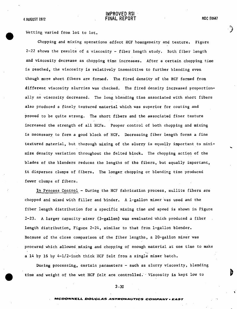
Wetting varied from lot to lot.
Chopping and mixing operations affect HCF homogeneity and texture. Figure
2-22 shows the results of a viscosity - fiber length study. Both fiber length
and viscosity decrease as chopping time increases. After a certain chopping time
is reached, the viscosity is relatively insensitive to further blending even
though more short fibers are formed. The fired density of the HCF formed from
different viscosity slurries was checked. The fired density increased proportion-
ally as viscosity decreased. The long blending time associated with short fibers
also produced a finely textured material which was superior for coating and
proved to be quite strong. The short fibers and the associated finer texture
increased the strength of all HCFs. Proper control of both chopping and mixing
is necessary to form a good block of HCF. Decreasing fiber length forms a fine
textured material, but thorough mixing of the slurry is equally important to mini-
mize density variation throughout the felted block. The chopping action of the
blades of the blenders reduces the lengths of the fibers, but equally important,
it disperses clumps of fibers. The longer chopping or blending time produced
fewer clumps of fibers.
In Process Control - During the HCF fabrication process, mullite fibers are
chopped and mixed with filler and binder. A 1-gallon mixer was used and the
fiber length distribution for a specific mixing time and speed is shown in Figure
2-23. A larger capacity mixer (3-gallon) was evaluated which produced a fiber
length distribution, Figure 2-24, similar to that from 1-gallon blender.
Because of the close comparison of the fiber lengths, a 20-gallon mixer was
procured which allowed mixing and chopping of enough material at one time to make
a 14 by 16 by 4-1/2-iuch thick HCF felt from a single mixer batch.
During processing, certain parameters - such as slurry viscosity, blending
time and weight of the wet HCF felt are controlled. Viscosity is kept low to
2-30
/MCOO/V/VEf.!. DOUGLAS ASTftOMAUTtCS COn*f*ANY • EAST

C
4 AUGUST 1972
/ ' • • ' : --Vfe^ti
10 SEC
10008%
600
400
200
100£* 80>
g 60
20
10
4S7-2S31
IMPROVED RSIFINAL REPORT MDC EOC47
$£j$^^~i3\--- -' •; \/d^k^TS>^sgrr^^*il
20 SEC
TYPICAL VISCOSITIES FORMODI, II, III AND IIIA
180 SEC
I I I10 15 20 25
BLENDING TIME-SEC
FIGURE 2-22HCF CHOPPING PARAMETERS
2-31
30 180
AfCOOJVJViE*.f. DOUGLAS ASTHOMAUTICS COMPANY • EAST

4 AUGUST 1972IMPROVED RSIFINAL REPORT HOC E0647
11in
UJ °1—
0
£m 6
It 5
UJ00 1=z
r—
„
—
LT»
1o
„I
Lrt
<3
gI
LO
aes
sLO
LO
"3
gi
u*»CSI
s
WPP
s1
s1
=>
§J,
10c* U1
1
RANGE: 0.0021 IN.-0.0976 IN.
AVERAGE: 0.0273 IN."
i : I I_ 1 i | j [ j | . . (in
s g s s c s g s s s s s K g s j s e s s s s s s1 1 1 t 1 t 1 1 1 1 1 1 1 I 1 t f 1 1 1 1 I 1 1
c> LO ^ (/> o to ^ LO o 10 ^ in ^ LTJ ^ to ^ LO ^ m ^ *o ^ m
— — — CN, « ;yS!
457-1395FIBER LENGTH - a 10'4 IN.
FIGURE 2-23
ONE GALLON MIXER
14
13
12
oilUJ
i 9o *QC "ul92 7LL, '
U. c0 0
CD 5s3z 4
32
o
-
-
__
—
—
L
~
LO
1
O
1LO
LO s1
*-
LO
t
g
•***•«
st
CNJ
P ~f
LO
1
LO
i
§1
M
ia
s
ai
S
£
1
s
RANGE: 0.0021 IN. -0.0976 IN.
AVERAGE: 0.0273 IN.
n i i i i; I li i 1 nil m
§ ' o L O C 9 L O O LO o LO o i-n ^ LO ^ LO ^ LO a 10 ^ LO ^ LO ^ LOLO r-- o cvi LO r^ o tsi LO r~~ ^ <vj LO r-. ^ rsj u^ t~~. o esi LO r-- o cvi
i i ( i i i i i i t i T T i i i i i i i i t i i t i
R ~ i £ ? p ; g 5 i ! 5 5 S W K R S 3 ! . 3 B S K S P : S S 3 S E 5 8 S
457-1394FIBER LENGTH - x 10"4 IN.
FIGURE 2-24
THREE GALLON MIXER
2-32
MCDONMELL DOUGLAS ASTRONAUTICS CO/*t EAST

IMPROVED RSI4 AUGUST 1972 FINAL REPORT MDCE0647
prevent excessive, felting time. The control-having the greatest effect on the
density uniformity finished product is the wet weight of the HCF blocks. By keep-
ing the wet weight within a predetermined band, the density and the strength of
the final product can be controlled.
As mentioned previously, a processing aid was added to prevent binder migra-
tion in the felt. The compound (hexamethylenetetramine) decomposes on heating,
and produces ammonia which gels the binder. During the heat-up cycle, the HCF
felts are inverted every 15 minutes to prevent binder migration due to gravity.
Since HCF is formed in a high speed mixer, the possibility of breaking the
hollow SiO_ spheres during processing was analyzed. An experimental batch of HCF
slurry (binder, fibers and spheres) was mixed for about 60 seconds (about twice
the normal mixing time) and the whole spheres were separated by water flotation.
Less than 7-percent of the total batch of spheres was broken during mixing. The
\^, test was repeated using only distilled water and Eccospheres to remove the effect
of the fibers. Again, the slurry was blended 60 seconds. Less than 5-percent of
the spheres batch was broken during this test. It was concluded that the broken
spheres, as seen in SEM the photomicrographs, are not broken primarily by the
mixing operation. See Figure 2-25.
Post Processing Control - Each processed HCF felt is cored and the density
and hardness gradients are determined for each large felt. Density gradient
records were kept to aid in the selection of acceptable HCF and to monitor process-
ing variations. If variation in density occurs, the HCF is evaluated for accepta-
bility. The hardness through and across each HCF felt is measured by the ball
drop test as discussed in Section 3.2.
In order to determine the reason for variation in strength, HCF specimens were
examined with a scanning electron microscope (SEM) to locate the filler (hollow
silica spheres) and binder. Figure 2-26 shows a specimen of HCF with a density of
2-33
MCDONNELL DOUGLAS ASTRONAUTICS COM PA MY • EAST

4 AUGUST 1972
IMPROVED RSIFINAL REPORT MDC E0647
457-2443
-SPHERES
SPHERES
FIGURE 2-25
HOLLOW SPHERE MORPHOLOGY IN PROCESSED MOD IHA HCF C100X)
Bf fj/£p^F*$Sf li** ^51*1!! ^ ^M f X*^?T~ • «S£j?iw 11&k^ i;>*, ;f *" ,,. • -; - m^ '/ l*^pgfp r , ^giy 'JS^Cl "
457-2443 FIGURE 2-26NORMAL FILLER AND BINDER DISTRIBUTION IN MOD IIIA HCF
. AS FIRED AT 2300°F FOR 3 HOURS
(300 X)
2-34
MCf>< 'A//VELC DOUGLAS ASTrtOKIAUTICfi COMPANY • EAST
c
IMPROVED RSI4 AUGUST 1972 FINAL REPORT NIDCE0647
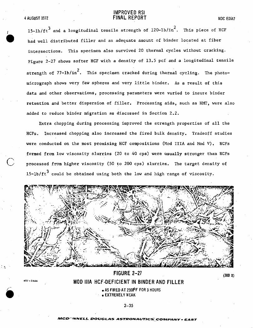
o 215-lb/ft and a longitudinal tensile strength of 120-lb/in . This piece of HCF
had well distributed filler and an adequate amount of binder located at fiber
intersections. This specimen also survived 20 thermal cycles without cracking.
Figure 2-27 shows softer HCF with a density of 13.5 pcf and a longitudinal tensile
2strength of 77-lb/in . This specimen cracked during thermal cycling. The photo-
micrograph shows very few spheres and very little binder. As a result of this
data and other observations, processing parameters were varied to insure binder
retention and better dispersion of filler. Processing aids, such as HMT, were also
added to reduce binder migration as discussed in Section 2.2.
Extra chopping during processing improved the strength properties of all the
HCFs. Increased chopping also increased the fired bulk density. Tradeoff studies
were conducted on the most promising HCF compositions (Mod IIIA and Mod V). HCFs
formed from low viscosity slurries (20 to 40 cps) were usually stronger than HCFs
processed from higher viscosity (50 to 200 cps) slurries. The target density of
315-lb/ft could be obtained using both the low and high range of viscosity.
V ' '•' "• • T.?*f J^W^^'^% ^-^S^x;
V^Sl^^wife|fe%4^tS^-,» . •-i^A^l.t-^A^ »^<r*/Si#i*jBi»f-«k.'i-<-- J*~ ' :J^ ^L^'f : \~• " - ^^^-^ • " :^^^K i ^^^^^>, . ' y-^^^tf '.^C/ 'vyv^ . •. :JL ' •'•i^vmv*' ^ *^^^^^^f^r*?^5^-! 2^ .--:
^Jfe^fi -^w:
437-2444
FIGURE 2-27
MOD IIIA HCF-DEFICIENT IN BINDER AND FILLER
• AS FIRED AT 2300°F FOR 3 HOURS. EXTREMELY WEAK
2-35
(300 X)
DOUGLAS ASTKOniAUTICS:.COmr»AIW • EAST

IMPROVED RSI4 AUGUST 1972 FINAL REPORT MDCE0647
3.0 HCF PROPERTIES
In this section are presented the results of the efforts to achieve the goals
of this program to improve mullite HCF ±n the following areas:
density control,
density gradients reduction,
strength increase,
strength gradients reduction,
thermal conductivity decrease.
3.1 PHYSICAL PROPERTIES - Overall density control and density gradient reduc-
tion were the major two physical properties of HCF which were concentrated on during
this program. The results of the efforts in these two areas are discussed in detail
in Section 2.0.
The efforts in both of these areas were successful. The overall density was
controlled to 15 +1 Ib/ft . Density gradients, which were prevalent during the
early part of the program, were essentially eliminated. The organic processing aids
and the density control during draining were two major factors which contributed to
the elimination of density gradients.
3.2 MECHANICAL PROPERTIES - HCF mechanical properties were measured through-
out this program to aid in screening materials. Various test methods were
evaluated for accurately determining mechanical properties. This section includes
discussions of the various formulations of HCF tested, test methods used and
results.
Strength Screening Tests - Mechanical property tests of various HCF formula-
tions were conducted to aid in guiding HCF development. Tensile and compressive, _ . * . -
properties were determined at room and elevated temperatures and both longitudinal
and transverse fiber orientations were tested. During this program several improve-
ments were made in test methods which resulted in more precise mechanical property
3-1
MCDONNELL. DOUGLAS ASTRONAUTICS COMPANY • EAST •<-

4 AUGUST 1972IMPROVED RSIFINAL REPORT MDC E0647
measurements. Room temperature tests discussed in this section were conducted at
MDAC-E. Elevated temperature tests which utilized an optical extensometer to
measure strains were conducted at MDAC-W and are discussed later in this section.
Test Methods - MDAC-E HCF mechanical property test specimens are illustrated
in Figure 3-1. All specimens were loaded to failure at 0.01 to 0.02 inches per
minute loading rate. Specimen densities, approximately 15 +1 Ib/ft , are listed
with test results.
Tensile Tests - Room temperature tensile tests were conducted on cylindfi-
cally shaped HCF specimens 1.29 inches in diameter by 1.0 inch long. Both longi-
tudinal and transverse fiber orientations were tested. Aluminum loading blocks
were bonded to the specimens with Scotchweld 2216 adhesive.* Loads were applied
to the aluminum blocks through universal joints to eliminate bending loads. Load
and strain were continuously monitored for room temperature specimens.
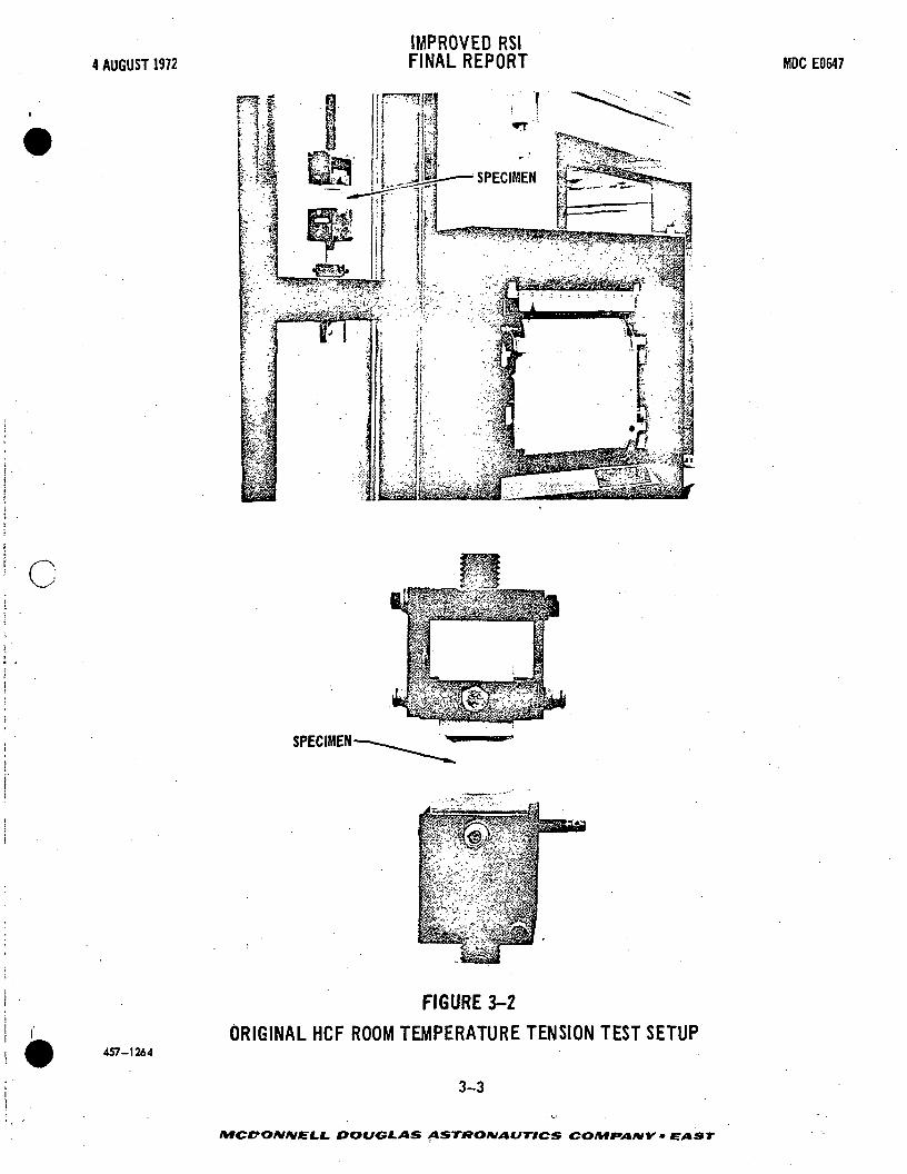
Methods for determining tensile strain were improved during this program.
Early in the program, strains were measured using test machine crosshead travel.
This original test setup is illustrated in Figure 3-2. Unreasonably low elastic
* 3M CorporationROOM TEMPERATURE TENSION AND ROOM ANDELEVATED TEMPERATURE COMPRESSION
U9-
ELEVATED TEMPERATURE TENSION
1.00
487-2436
NOTE: ALL DIMENSIONS IN INCHES
FIGURE 3-1HCF MECHANICAL PROPERTY SPECIMENS
3-2
/HCDO/V/VEJLi- DOUGLAS ASTRONAUTICS COIYIfAfHY - EAST
4 AUGUST 1972
c
457-1264
IMPROVED RSIFINAL REPORT
SPECIMEN
FIGURE 3-2
ORIGINAL HCF ROOM TEMPERATURE TENSION TEST SETUP
3-3
MDC E0647
DOUGLAS ASTRONAUTICS COMr*AMY • EAST

IMPROVED RSI4 AUGUST 1972 FINAL REPORT MDC E0647
moduli were obtained using this test method, and it was concluded that machine
crosshead travel could not be used satisfactorily to compute strains. As a result,
the test setup was changed to include the use of a clip-on displacement gage attached
between loading blocks. Two clip-on displacement gages were used on opposite sides
of each specimen as illustrated in Figure 3-3, in order to compensate for cocking of
specimens,.
The double cantilever clip-on displacement gages are composed of strain
gages bonded to cantilever arms. The displacement gages were calibrated by relat-
ing strain gage output to displacement of the cantilever arms. The gages were
attached to two sides of each specimen to compensate for differential strains due
to specimen misalignment or nonuniform specimen density. The gages were accurate
to within 0.0003 inch per inch.
Elevated temperature tensile tests were conducted at 1200°F, 1800°F, and
2300°F. The test setup is illustrated in Figure 3-4. Coated columbium grips»
were used to load the specimens. Ten-inch quartz lamps rated at three hundred
sixty watts per inch were used to heat the specimens. Specimens were heated to
test temperature in approximately 3 minutes and allowed to soak at test temper-
ature for 3 minutes prior to testing.
Compression Tests - HCF compression tests were conducted on cylindrically
shaped specimens 1.29 inches in diameter by 1.0 inch long. Both longitudinal and
transverse fiber orientations were tested. Tests were conducted at room tempera-j ~
ture, 1200°F, 1800°F, and 2300°F. Load and strain were continuously monitored for
room temperature specimens./
Methods for determining compression strain were also improved during this
program. The original test setup is shown in Figure 3-5. Specimens were com-
pressed between machine loading heads and strains were determined from machine
cross-head travel. It was found that a large portion of the strain obtained from
. _ . - . - - ' • -- 3-4 - '
DOUGLAS ASTBOMAUTICS COMPANY • EAST

4 AUGUST 1972IMPROVED RSIFINAL REPORT MOC E0647
C
^LT—yj PLOTTER ! |
437-2170
DISPLACEMENTGAGE
ALUMINUMLOADING
BLOCK
UNIVERSALJOINTS
FIGURE 3-3
IMPROVED HCF ROOM TEMPERATURE TENSION TEST SETUP
3-5
MCDONNELL DOUGLAS ASTRONAUTICS COMPANY • EAST

4 AUGUST 1972IMPROVED RSIFINAL REPORT MDC EG547
457-2109
FIGURE 3-4
HCF ELEVATED TEMPERATURE TENSION TEST SETUP
3-6
MCDONNELL DOUGLAS ASTRONAUTICS CO/Vf*V»/VK- EAST

4 AUGUST 1972IMPROVED RSIFINAL REPORT MOC E0647
457-1265
:&'>>?:-i ?-::~ ; 4s: v^-C^ fe^^^^s
FIGURE 3-5OJlJGftlAL HCF ROOM TEMPERATURE COMPRESSION TEST SETUP
3-7
DOUGLAS ASTRONAUTICS CO/V»*V»*WV • EAST

IMPROVED RSI4 AUGUST 1972 FINAL REPORT MDCE0647
machine cross-head travel was due to local crushing at the ends of specimens. The
crushing was eliminated by bonding the specimens to aluminum loading blocks with
Scotchweld. 2216 adhesive. Strain measurement accuracy was improved by using a
clip-on extensometer attached between the loading blocks. The final test setup
used two double cantilever clip-on displacement gages as illustrated in Figure 3-6.
The elevated temperature compression test setup is illustrated in Figure 3-7.
The ends of the specimens were coated with Sauereisen No. 78* ceramic cement to
prevent crushing. ATJ graphite cylinders were used to load specimens and 10-inch
quartz lamps were used to provide heat. Specimens were heated to test temperature
in approximately 5 minutes and allowed to soak for 3 minutes prior to testing.
Test Results - Mechanical property screening test results are listed in
Figure 3-8.. Properties were determined for a group of experimental materials
with different fillers, Mod I, Mod II, Mod III, Mod IIIA and Mod V materials. ^
The composition of each material, as well as firing temperature and density are
defined. Specimens were tested in the "as fabricated" condition and all specimens
were loaded to failure. Both longitudinal and transverse fiber orientations were
tested. Ultimate strengths were obtained by dividing ultimate load by specimen
cross sectional area. Elastic moduli represent the slope of the linear portion of
the stress-strain curve, and the footnotes used in Figure 3-8 indicate the various
types of strain measurement used. Stress-strain curves for both tension and com-
pression are generally linear to failure. Typical stress-strain curves are shown,
in Figure 3-9. Stress-strain data were recorded for all room temperature test
specimens. Typical tensile and compressive failures are illustrated in Figure
3-10.
Elevated Temperature Mechanical Properties of Mod IIIA HCF - One goal of
this program was to develop methods for accurately determining HCF mechanical _2
* Sauereisen Cements Company
". "" 3-8 ~ " ' "~ '
MCDONNELL DOUGLAS ASTRONAUTICS COMfA/VY • EAST

4 AUGUST 1972IMPROVED RSIFINAL REPORT MDC E0847
c
457-2111
'fitter fiff
1 tlli - ' i\ r _ iTffSffl rii_':*r.'-*>&?£& J& t '
J-S^ i ^aeM^ '-•',<?7°*\
i«__r»,--"3&
d' ^^rs.' f^^^r^S' l• ,.tr-.'/-4yff>^f,^ ' : ••'"'.'*;«
:^Sf4:-^;-
•I.-*..'-..' -,-_;^! •, ,^. -'\-/-'" -1"*- -."V ...
IMPROVED HCF ROOM TEMPERATURE COMPRESSION TEST SETUP3-9
/VfCDO/V/Vf Ll. DOUGLAS ASTRONAUTICS ~ EAST

4 AUGUST 1972IMPROVED RSIFINAL REPORT MDC El'647
457-2110 FIGURE 3-7HCF ELEVATED TEMPERATURE COMPRESSION TEST SETUP
3-10
/VTCOO/V/VE-I.C. y»sT-wo/vx»t/r-/cs - EAST

4 AUGUST 1972IMPROVED RSIFINAL REPORT MDC E0647
PRO
PER
TIES
Ut'
$
I
PRO
PER
TIES
I3too
£Ik
_i1J blo: t—O U.'
Z 1—
* o:
|£
i
sa£g<_>
S«/i
ZUJh-
IJ3UJQ=
&
3
if| =
SPc£ -a
s—
3
IfegSi
MA
TER
IAL
DES
IGN
ATIO
N
iu"
3
uT
3
uj"
3Lk
UJ
U.
UJ (j
| fesil oi g££S a§ Si§S -3 iSas 2£ g g £ S AS= - z d ~ = "~" S = = ~ £S^ < = l a E = ^1iotu ujriu^ f^z
dS sgsisi^«S So- = >->-=co
1
5
S — S S !C — " S S S ^ ^ ^ S S J C J p S — — £> — £ S > 5 S 3 3 J C
S S S R S 3 2 ^ S S - - 2 2 2 ^ 2 2 S S S S S ! G K 3 » S : S
Gt
c 3 o o ^ ^ ^ ^ « ^ o e 3 ^ c b r t c ^ ' * 1 ^ 2 c 5 ^ S ^ * ^ « «I ^ S3 ci ^g u O O u - l r — ^ E ^ S O j g ' J ^ O n O O ' ^ ' - O g ^ ^ ^ Z Z ^ *^
_^— . — — — — — — W- — —. — — — — — - . — — . — — — — — — — — —
s S S S 3 S S S § S § S § § g § S S § § ^ 8( c« <s» (si rw" p*T cJ cxi (vT <-u *vl' rs* CM" (si <N." oj «-j rsi rsi" «^ f
ts> t/i
& i ia i d£ 2 2* g g£ O O v>
| a^ _J5 ^ 5
S§ Sg g rf.*«BBg£ Sl ^S S 3-5H2SS = SSUJ™ U.O. O- -J _ J < U . U . U . U . O U U U
Ss S o o o o o 5*o o" c £0o'o o o*c?taJ- " W- "-_ J ^ - O ^ *
< J < J <- > ' ^
a e * ' ^ ' t J O O O «s. *\(^ < « <^ M S " « " < j - J u j ujo o o c j o o -FITS 533
T ' t l 7 T 7 f 7 T ' ? 7 T 7 T 7 7 - - 7 7 7 T ' r 7 7 7 * r 7 ' r 2
Hii111 =UJ U- " O
X
£3 Z „0 <= UJ J= £
ill! !!u- E 3 n uJ •"gas" °so 2. x u- ^~ C(D S UJ 0 0 £— — • a as uj •2. •£. u> <c »-
CM
'3§ 2«»» «»? rK
SS »
c
i §s" —
K »
~
£|§S§S|Sg|g| gg § SS
— t -»<*» jNgp j«o«^«g»2 SR S 53 —««£.SlNI^— — . — — .^ (Mtsj — — —
•• •- - S
iillisiililiil § ? I
^SZ'°*s 'SIn«K^^'~" l '> ' ** iS S S "*
s . , S 3 S S S 8 . .§
? f 17 22& ^ 2 2 - ^ 2& S S ? S ? £ £ £ £ §
U O> O (NI (uU O (J O (_>o t j c j i , o c j T o t iUl UJUJ^ M U J U J ^ i U J UJ
^ Si^ ^" £fg£ ia. a a •< 5 a a. < a. a
10 10 bp t/t l ^ l « 0 ( A I ^ I A fcO
U. C, X _ U. •? V ? ? f? V f V?^-> CM ^ — « «st «« I I 1 l l r - . r - . f - f l O « o « n < T v O « O
r « t ^ ^ a » « v « r > r f ^ ' t o » . . « v . H _ H V M v _ a . « « « « . M r « c 4 ( s j r i > t
M S 2 — R S R 5 * 5 5 S S S 2 5 S
i
UJte.
T £CO -_
OS ==
U. CC.O
3-n
E-f-I. DOUGLAS ASTKOMAUTICS COMf»ANY • EAST

4 AUGUST 1972IMPROVED RSIFINAL REPORT MDC E0647
PROP
ERTI
ES
S
TRAN
SV'E
L PR
OPER
TIE
«
3
^
a<K
C
Ktf
flA
KK
S A
DD
KtA
SU
HS
FOR
TEST
S
|
1
g
UIt—
i
1o
g5
5"ES* CD
d
UJa:=>
S"UJ-
s
»
r
isII
IM
TER
IAL
OESI
GNAT
IOM
uT
3u.
uT
=u.
uT
3u.
UJ
uT
fe£ u- u-
as II£g K3 SP o *~ *~K a « _ _ «0 d 0 * * oSo IS Sa s a s1— O t— 1—
^Iirt
trt
ISi
un
5
S o **> e» g es5 r»- a S o
oa" to •*> W < f <=>"
ss 22§=
ci
11 ii § Z K Z §•A **» r-T *X lA
ss .as ss-=s
° . r 8
rsi *v»
O O' O Ru o U £<E oe o= —N N'S ^
£ i! £ «7 77 *"*CQ _ cfl.ra fS£ ffi.fi: " ^E.o o o 2s ss gUJ UJ UJ
£ *£ »^ a a £
ouJU-Of lnVouJu-ox^r^l l l l | l | l l l l l l ^ . v m u >
i 32. Sllll
i
ROOM
TEM
PERA
TURE
TES
TS O
NLY
|
§*fi
X
_
§a
s
i
S3
^
s
s
AV
ER
AG
E
aV- uj O
- S »i3 Z S gS5gg £»Sfel Is= = g ft £fe-Sp . S3o^iJig g^|iii ii3E 0 -1 = s 0 «ro ft: LU */» o o —U 0. <J > S Z =
_ S 5
1 Is3§ 5s s• ff <e trt *e" i/f irt" ui"
a s s x s s ~ s
G **"
I §ii§ is if1 ss'ss sa 5f
s S S B S a» as
ts
S gooo ^ 9 S 9 SI gas RSlI I.
s 2 5S5 5S5 : ?
=
S 8 g S SS SS §§8o c a S o ^ x < 5 > s * O i s i taioo
3 S's?Sz SS 53 • . 9 XS
5 '5.2S5 ' R S 3 S S K S
S . ,_ s~ ~-
a ai Is . • . d2 -2"fcfi"" K-£8= S*UK UKui 2u • ui u
si si58 5iS
mu«o »ou -OB i t j u . - czzZ i>>5 — <SI"*' —i r i i < u u o u . c 3 u J K e o o < e a u J X u . o c a o u . c 3 n o u . z U < < o u i u J u a . a.7 7 T T 7 T 7 7 T T 7 7 7 7 7 7 7 7 7 7 7 7 T T 7 7 7 7 T T 7 7 7 7 7 g SS 5 2 5 f C ' . - f i S S
<
i
Q1-Zny0-rxinM
tin•*T
a>3C
OO
COUJoc
UJh-CD
a:o
oUJoc.
3-12
oo(yc<->ts XISTWO/VX»C/T-*CS co/vrna/vv • EAST

4 AUGUST 1972IMPROVED RSIFINAL REPORT KDC E0647
-
PRO
PERT
IES
UJ
£g
yi£<
S0
C1
£
u.
KU
BA
N*)
AN
D K
LA
WN
5FO
R TE
STS
1Ul
is
sXUJh-
S
O
5t-
$t§s
*si
i—
1
i§Si
SS
{M
AT
ER
IAL
DE
SIG
NA
TIO
N
uT
Su.
uT
3u.
uj"
3
UJ
J!
11 §*» 10 i»»
sss
>
ill.-is
a = s
111 i§
SS* a =
= rSSS 3°o <5 «-i 25 i/»
= 2= 2 z
S3 s ss
mirioi i j '»>j- iu- iLOuwiqiu'*covd^u">™a
3 . - 8
c* fN»
a1 #»z p£ *j
1 15; " •- yttK ' (K
O O
uT u.'S •
J> «a
T f ? 1"r f 7 f -f f f ? T f T I15 S
O
S
_
ito
S
—
1K
•
i
_
_
Is^
AVER
AGE
dU.
|sUJ ul
E ujfe t
21
§S I^ *-j «**
0s ;;
5
I §§CNi — T r-."
S 2J3
rvi
£ ? . s > a ^ r 3 cvj Jl m u ^ . u i p ^ rsi^jg eaS r~ r*. & w O
^ 9 ^ « »S 3 S — S KIS SJ5S SS iS« £
»C m
§ S 8 S S 8 S3 8§ §8 S3 SS • "g 8<~t ifi Q Q Q iff o 100 S ur» U3 ^ ^ vn • (So
"~~ ' " -2 =- -= 22 2= =s sa
S S » S » f 3 *3 S^ 33 SS SC SS
"""" " " " " . .ss a a a s a s s sa as s a ss sss a a sss „ -8csi csi «sj r* «si rj r*j «">J c«J j «^ <si esi «si (sj isi CM' *** r*J «*ii i*«* cvj *>j «"« «*-J ^
S SS £U N
i7 ri rtSfS f ~~ ~
• "= T ~ m m 10 <o
7785i . ^B BB ' BS S .fft . ' — ' "' " ~ •' * o — " o o •" ^o< * K - > = ° ' gS Su5 • S
gii'g'S S" Vf VS UJ UJ UJ 1 ^ UJ UJ UJ UJ
u," u." u." u." u.' u,' a x s cm m m m x » a a a aiA uo u> ^a <-o IA W •* W •»
« c a € j o < ( D c j o < a i c j c i « o D ( _ } o * X ( D ( _ > C > < x c o u o m ( _ > o o a < x c D o u J u . oi i i ' i i i i i i i i i i i i i ( i i i i i i i i • i t i i i i i r
7 7 7 7 7 77 77 7J "T ? ; £ 1 > - f 7 7 7 T 7 7&' rsi'3 *f? m m«n S *-> (£**i mm ! £ « ? * ? * ? ^
I
8
S
1(SI
ilO
/>
iS
s
AVER
AGE
S>-*zo
&•KCN
1
R*r
o>
oO
</»
tyOUJ0=
ooUJ
CD
a:ooo
CD
UJCC
<s»
3-13
MC DO MM ELL DOUGLAS ASTftONAUTHZS COMPANY - EAST

4 AUGUST 1972IMPROVED RSIFINAL REPORT MDC E0547
QC
1
TRAN
SVER
SE
u
^
1
U
U.
0 RE
ASON
SES
TS
Sss'i
§3
iUJt—
oa£§O
s
H-
if5 a0 -j
K-Su
h-
D
3
srt
cm
tnNU
MBE
RI
MIfc
KM
LDE
SIG
NATI
ON
UJ
u.8
uT
uT
uw"
3
UJ
^
Q =Z U. H-«* o -J «
L I! II 1£ = £i 5g ifeu! ££ SS o sililllllllliZ0 z i; z v, - ~ <- ~~~
p o ,_ g i-i-- o «t<£«<*t«t -K««<t-<«*<r•* 3 *f rr- «< OS S a- Q O O O O O O O O O Q O O13 » = S =UJ= £ uJtUUJUJlUUJUJUJUJLlJUJUJUJ-1 z -1 rt -J Q_ Q > _ j _ ^ ^ _ t _ t _ K - t - k - t - » - t - t -< £ *t " < O O ;= t X V L ^ t / l t ^ V l M V t t ^ l i O M t ^ b ^ t O^= > Z ? O C O £ UJUJUJUJUIUJUIUJLUUJUJUJUJuj ij? uj m UJO.E to t— t— t— t— - t— i— >— t— t— > — * — > —
I igssss » »•
= 5§2§s
IS! !§ii§»SS a ~ ss-'s
3 3 S X S S S S
§ S S S S 8 S «<« <•*r ^ i A S r ^ r * , , ^ K V Z z z
s » B'« a a s
5 * =~ * s = gss §s
!§§!§ | §11 gll§ S2g S S S S SiS £ S R' R IS S S * S « S »
a a s a a = s % s xt:Si- ass as-n-
( M ^ r ^ t n r N ^ i n o t ( M « « f ^ ^ < s 4 — • ^ r » 4 4 ^ ^ i A i a ^ i / i ^ a f t < ^ » « * > > < ^ ^ V t « r ^ r ^ p ^ « A « ~ ^ ( < k « i / f t 0 4 4 4 4 ^ 9 i « at A t n t ^ k / i i ^ u ^ ^ i / i ^ - v r W ^ ^ V f ^ m t e i ^ w ^ ^ ^ i n t ^ w ^ M ^ t f i i n r ^ ^ f ^ i i ^ ^ u ^ w ^ W W u S W i r i J C Z K Z Z t X t / i
8 , r §^ " : - ~
U» t/>
1 1UJ UJCJ 0
aa GO
8s 8*as asu,* £ ij £C ^ . E 3C
aS it!w S 3 *
T 7 7 T 7 7 7 T l ' ? ' f T c 7 f u o " o T ? ^ „ «= u^ -.oa.«N» tvi u*> lA ^. T-. 1 1 t 1— — ™^ ( -MC* ) ^^ f f l — . — trttj^. — p w r o _ - « ^,fcO«rt — «* t - rCOUJf t t li (— — « v r > * | » ; - f | | i / » m * p — . t s j i f — ™ -- O. £L n. ) 1 I n. Q. — —
»A Jl f— r- r-» -, 1 1 1 1 <*. «rt r- ^ . l l T l t < r » < r . t l l e o o p o p o - . i T . ( 7 i e 3 Oil2 ~2 22 ^ ^ " Z — « — 2 Z22l iKJC — — «<C?33»^r: r :z ;5 35S
ioi
5g
h-
5p!SS-s>—
5
s
is
5»
Cn1
e
^
is"
S
AVER
AGE
0 SUJ ' C1
S? S3UJ 0
0 g
- tCO o< s
§1 Is s" . s
S S 2
S§ 1112as s s te
— M N 0 r^ _.
« 0 ^ ( 0 ^ i / > V B t A U B t ^
^ . . f
P>* ^
i'1*' 2i ££•" <2~
" c?«s* •
E *
»H- r? ~ t
jDS2-r . -~-1 t | | f- »_ »- »- H-— — a_ a. a. a. x
s slllls
>
c.f-zo
or^*nCN
1l«v*n•n
o>c
o
CO
UJOS
UJI-CJ
ono
CD
UJa:C/l
3-14
ooc/ci.>as ASTRONAUTICS connr*Aiw • EAST

4 AUGUST 1972IMPROVED RSIFINAL REPORT MDC E0647
c:
s .
nf
2: uj »_
uj oe5gu al
*i
*l
seaast- o
1SI" "
» s s R a a"
S S 5S
-: s
— — .z Q . Q . Q - 0 - z z z a . Q - a . Q . z
B"
OO
CO
=3CO
coLU
O
LUO=OCO
C3ZLUa:CO
all:S
§ a(£ Ku. £ ^ ^ ^
S i ^ i x « U j a . . , , u j ^ n r ?( c u j e e ^ y i z i j o o
Is lslss^ga0 > U - £ f e B 3 j i u . u .U J u J ^ 2 i ; n ^ i ^ > Q O O
55§a5.55i5gs— I — l u j > - U t - X _ t < X <o 3 —* ztO >— o ce aE S E T i l k U J Z U J O U O
_JSjUJ UJ Z S (Q= P=. S 3 '
uj as5- o o vTi 7~ G D U . U U 1 'l <*£
^ o S g g ^ w Z
e o g S . . U
3-15
/V»Cr?O/V/VEf-C DOUGLAS ASTffO/VAUT/CS • EAST
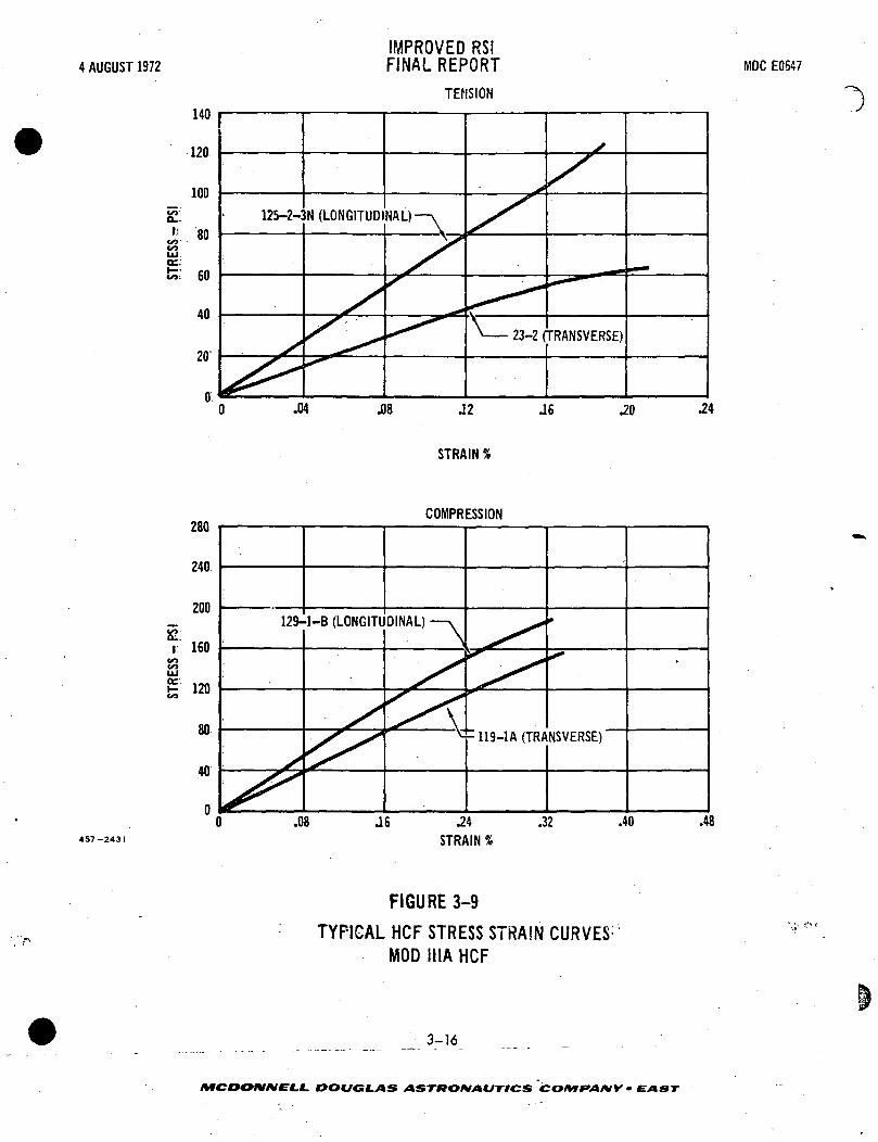
\ AUGUST 1972
sc:l;.
COUJ
fc; 60
IMPROVED RSIFINAL REPORT
TENSION
MDC E0647
125-2-3N (LONGITUDINAL)
STRAIN %
COMPRESSION
129-1-B (LONGITUDINAL)
457-2431
.24
STRAIN %
FIGURE 3-9
TYPICAL HCF STRESS STRAIN CURVESMOD IIIA HCF
3-16
AffCDOJV4VfC.f. DOUGLAS ASTKOKIAUTICS CO/MFAtVY • EAST

4 AUGUST 1972IMPROVED RSIFINAL REPORT MDC E0547
i .^
7 • " " • ; • " • ' - • ' '
'&
TensionSPECIMEN NO. 322R
(REFB)
>,' '••*jp->,'
;.i)* ••:1 -• t ^^ ^,
•'^"•l
^ ...'ii! .: .'.'V-i. A«a.JAL. aLi35 .i. --*
...~#^
' fj; >'
l '••-
r.,.v. «--- 1
2**! i^»
;' •'•£-'.'*:£
-;•- -.., ;'M'V:.<--^;. ; ^ ,^,?,J $.&- ' jt yfl
Compression
FIGURE 3-10
TYPICAL FAILED SPECIMENS
3-17
SPECIMEN NO. 322M(REF B)
DOUGLAS ASTKOftJAUTICS COMPANY • EAST
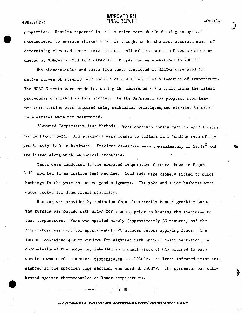
IMPROVED RSI4 AUGUST 1972 FINAL REPORT MDCE0647 ~
properties. Results reported in this section were obtained using an optical
extensometer to measure strains which is thought to be the most accurate means of
determining elevated temperature strains. All of this series of tests were con-
ducted at MDAC-W on Mod IIIA material. Properties were measured to 2300°F.
The above'results and those from tests conducted at MDAC-E were used to
derive curves of strength and modulus of Mod IIIA HCF as a function of temperature.
The MDAC-E tests were conducted during the Reference (b) program using the latest
procedures described in this section. In the Reference (b) program, room tem-
perature strains were measured using mechanical techniques, and elevated tempera-
ture strains were not determined. „
Elevated Temperature Test Methods - Test specimen configurations are 'illustra-
ted in Figure 3-11. All specimens were loaded to failure at a loading rate of ap-
proximately 0.05 inch/minute. Specimen densities were approximately 15 lb/ft3 and ^
are listed along with mechanical properties. '
Tests were conducted in the elevated temperature fixture shown in Figure
3-12 mounted in an Instron test machine. Load rods were closely fitted to guide
bushings in the yoke to ensure good alignment. The yoke and guide bushings were
water cooled for dimensional stability.
Heating was provided by radiation from electrically heated graphite bars.
The furnace was purged with argon for 2 hours prior to heating the specimens to
test temperature. Heat was applied slowly (approximately 30 minutes) and the
temperature was held for approximately 20 minutes before applying loads. The
furnace contained quartz windows for sighting with optical instrumentation. A
chrome1-alumel thermocouple, imbedded in a small block of HCF clamped to each
specimen was used to measure temperatures to 1900CF. An Ircon infrared pyrometer,
sighted at the specimen gage section, was used at 2300°F. The pyrometer was cali- «
Ibrated against thermocouples at lower temperatures.
- . - - - 3-18
MCDOIV/V£LL DOUGLAS ASTTttOMAtJTICS-COM f»AIMV - EAST

4 AUGUST 1972IMPROVED RSIFINAL REPORT MDC E0647
c8.0
TENSION
CD
NOTE: ALL DIMENSIONS IN INCHES
COMPRESSION
20) R
0.510)0 R-
CD.X
-1.0-
\ )
-.500 DIA
-0.31.5-
3.0
\
X1.0
457-2545
-—1.5
FIGURE 3-11
HCF ELEVATED TEMPERATURE MECHANICAL PROPERTY SPECIMENS
3-19
MCDONNELI. DOUGLAS ASTRONAUTICS' COMPANY • EAST
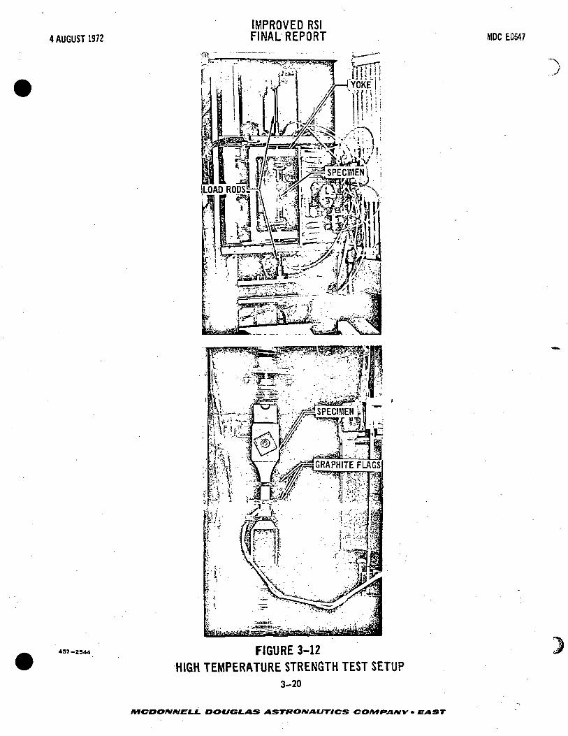
4 AUGUST 1972IMPROVED RSIFINAL REPORT MOC EC547
497-2344
r-, \ *y*f v^^y^C^K?^^--
Ml \"> lu/h-
FIGURE 3-12HIGH TEMPERATURE STRENGTH TEST SETUP
3-20
MCDOMMELL DOUGLAS ASTRONAUTICS COMfAIW • EAST
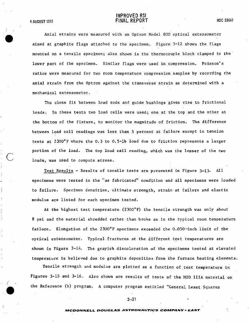
IMPROVED RSI4 AUGUST 1972 FINAL REPORT MDCE0647
Axial strains were measured with an Optron Model 800 optical extensometer
aimed at graphite flags attached to the specimen. Figure 3-12 shows the flags
mounted on a tensile specimen; also shown is the thermocouple block clamped to the
lower part of the specimen. Similar flags were used in compression. Poisson's
ratios were measured for two room temperature compression samples by recording the
axial strain from the Optron against the transverse strain as determined with a
mechanical extensometer.
The close fit between load rods and guide bushings gives rise to frictional
loads. In these tests two load cells were used; one at the top and the other at
the bottom of the fixture, to monitor the magnitude of friction. The difference
between load cell readings was less than 5 percent at failure except in tension
tests at 2300°F where the 0.3 to 0.5-lb load due to friction represents a larger
portion of the load. The top load cell reading, which was the lesser of the twoc—^ loads, was used to compute stress.
Test Results - Results of tensile tests are presented in Figure 3-13- All
specimens were tested in the "as fabricated" condition and all specimens were loaded
to failure. Specimen densities, ultimate strength, strain at failure and elastic
modulus are listed for each specimen tested.
At the highest test temperature (2300°F) the tensile strength was only about
8 psi and the material shredded rather than broke as in the typical room temperature
failure. Elongation of the 2300°F specimens exceeded the 0.050-inch limit of the
optical extensometer. Typical fractures at the different test temperatures are
shown in Figure 3-14. The grayish discoloration of the specimens tested at elevated
temperature is believed due to graphite deposition from the furnace heating elements.
Tensile strength and modulus are plotted as a function of test temperature in
Figures 3-15 and 3-16. Also shown are results of tests of the MOD IIIA material on/
the Reference (b) program. A computer program entitled "General Least Squares
3-21
AfCDO/V/VELL DOUGLAS ASTRONAUTICS COMfVl/VK • EAST ';
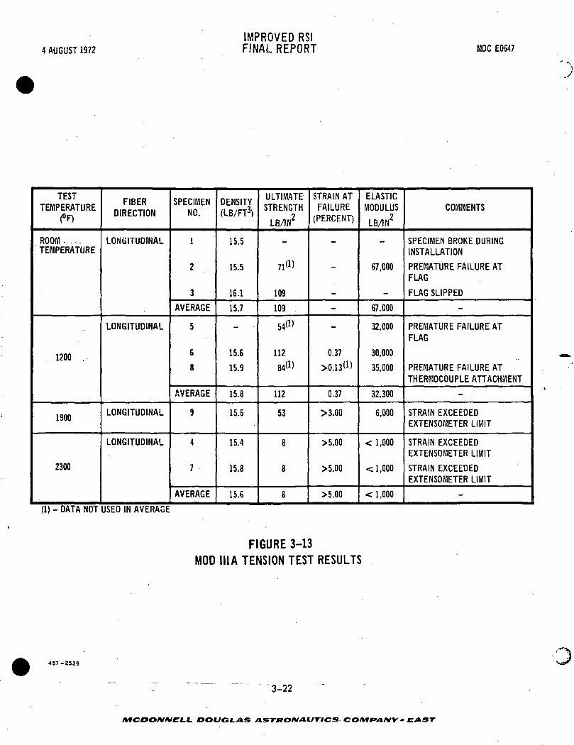
4 AUGUST 1972IMPROVED RSIFINAL REPORT MDC E0547
TESTTEMPERATURE
(°F)
ROOM .....TEMPERATURE
1200 .
1900
2300
FIBERDIRECTION
LONGITUDINAL
LONGITUDINAL
LONGITUDINAL
LONGITUDINAL
SPECIMENNO.
1
2
3
AVERAGE
5
6
8
AVERAGE
9
4
7
AVERAGE
DENSITY(LB/FT3)
15.5
15.5
16.1
15.7
—
15.6
15.9
15.8
15.6
15.4
15.8
15.6
ULTIMATESTRENGTH
LB/1N2
_
71(D
109
109
54<«
112
84»)
112
53
8
8
8
STRAIN ATFAILURE
(PERCENT)
_—
-
-
-
_
0.37
>0.13<D
0.37
>3.00
>5.00
>5.00
>5.00
ELASTICMODULUS
L8/IN2
L^
67,000
-
67,000
32,000
30,000
35,000
32,300
6,000
< 1,000
< 1,000
< 1,000
COMMENTS
SPECIMEN BROKE DURINGINSTALLATION
PREMATURE FAILURE ATFLAG
FLAG SLIPPED
-
PREMATURE FAILURE ATFLAG
PREMATURE FAILURE ATTHERMOCOUPLE ATTACHMENT
-
STRAIN EXCEEDEDEXTENSOMETER LIMIT
STRAIN EXCEEDEDEXTENSOMETER LIMIT
STRAIN EXCEEDEDEXTENSOMETER LIMIT
-
(1) - DATA NOT USED IN AVERAGE
FIGURE 3-13MOD IIIA TENSION TEST RESULTS
457-2539
3-22
MCDONNELL. DOUGLAS ASTRONAUTICS COIVIfANY • EAST

4 AUGUST 1972IMPROVED RSIFINAL REPORT MDC E0547
r
457-25S1
1RJJ ;jl2000Fi )l900°F!''*<-TJJ*Hl - ' ']"ty*Vr..':!fU.t$y-''-'. , . •'£3-y?.*£f.*!f|- .
• jftfi'ntifi'* '. ' :^^>^^*^. -' ' '. •J A&.JaLrC^ ^ -
FIGURE 3-14
TYPICAL FAILED TENSILE SPECIMENS
3-23
MCDONNELL .DOUGLAS ASTRONAUTICS COMfAIVY . EAST

4 AUGUST 1972IMPROVED RSIFINAL REPORT IVIDC E0647
14U
120
100
£
STRE
NGTH
oo o
UJ1
<s>
UJ
£ 60
g
40
20
0-5
&xD
oD
D^SVXD ^X,
D
X
D
O
\DV
>u
D
O MDAC-WE 5T TESTS
g PREVIOUS TESTS(REFERE
^X.>\
*JCEB)
D
\D
D
0
10 0 500 1000 1500 2000 25
457-2543
TEST TEMPERATURE °F
FIGURE 3-15
HCF LONGITUDINAL TENSION STRENGTHMod III A
3-24
/VfCDO/V/VEJL*. DOUGLAS ASTfTOMAtJTICS COMPAMY • EAST

IMPROVED RSI
c
4 AUGUST 1
80
60
i</*3
O
1 40
LU1-
20
0-5
972 FINAL REPORT MDC E
D9n
VD\
\X^o
O MDAC-W
D PREVIOU(REFERE
\0
TESTS
; TESTSNCEB)
00 0 500 1000 1500 2000 25
TEST TEMPERATURE °F497-"47 FIGURE 3-16
HCF LONGITUDINAL TENSION MODULUSMod III A
Analysis" was used to fit the data to linear least squares curves. The data fit a
straight line relationship adequately; therefore, it was not necessary to consider
higher order equations.
Compression test results are given in Figure 3-17. Typical compression failures
are illustrated in Figure 3-18. At the higher test temperatures the longitudinal
specimens did not break but only bulged. As can be seen in Figure 3-18, there was
an appreciable expansion in the transverse direction at the center of these specimens,
Longitudinal compression strength and modulus"'are plotted in Figures 3-19 and"
3-20 and transverse compression strength and modulus are plotted in Figures 3-21
and 3-22 as a function of temperature. Also shown are results of previous tests of
3-25
MCDONMELL- DOUGLAS ASTRONAUTICS CO/MfV*/VV • EAST

4 AUGUST 1972IMPROVED RSIFINAL REPORT MDC E0647
TESTTEMP.(°F)
ROOMTEMP.
1200
1900
2300
FIBERDIRECTION
LONGITUDINAL
TRANSVERSE
LONGITUDINAL
LONGITUDINAL
TRANSVERSE
LONGITUDINAL
SPECIMENNO.
23
AVERAGE
45'6
AVERAGE
131415
AVERAGE
89
AVERAGE
101112
AVERAGE
7
DENSITY(LB/FT3)
15.815.5
15.6
15X15.815.9
15.5
15.9 (1)16.015.3
15.7
16.615.8
16.2
16.517.017.1
16.9
16.7
ULTIMATESTRENGTH
LB/1N2
230247
238
9796
105
100
233227
230
3657
47
272430
27
10
STRAIN ATFAILURE
(«)
0.170.22
020
0.430.30
0.35
OJ50.13
0.14
__
—
E——
ELASTICMODULUS
LB/1N2
145,000114,000
130,000
36,00025,00037,000
32,700
127,00081,000
104,000
91,000120,000
106,000
1,800900
1,100
1,300
—
. COMMENTS
u = 0.160(2)
—
n = 0.093(2)
' —
ENDS OF SPECIMEN CRUSHEDDURING LOADING
—
—
—
(1) DATA NOT USED IN AVERAGE(2) POISSON'S RATIO
FIGURE 3-17
COMPRESSION TEST RESULTS
MOD III A
457-2349
3-26
DOUGLAS ASTttOMAUTICS COMPANY • EAST

4 AUGUST 1972IMPROVED RSIFINAL REPORT MDC E0647
iRT TRANSVERSE |1SQ00F LONGITUDINAL i2300°F LONGITUDINAL
c »'&3&g!&*%!Rfv*;P -'-'*5>^ "*•T Sn^ r rt?*
457-253Z
2300°F LONGITUDINAL'
FIGURE 3-18
TYPICAL FAILED COMPRESSION SPECIMENS
3-27
/VfCOO/V/VfLJ- DOUGLAS ASTRONAUTICS COMF*A/VY - EAST

4 AUGUST 1972IMPROVED RSIFINAL REPORT MDC E0647
10U
O*nitv
200
icn1DU
lift1ZU
onOU
40
\
DD
a
80
a
>^
\\
a \\
oo
D
\X
O MDAC-V
D PREVIOU(REFERE
\\
O
o
TESTS
S TESTS.MCE B)
\
§0
-500 0 500 . 1000 1500 2000 251
LUCC.
OCQ.
OO
437-2550
TEMPERATURE °F
FIGURE 3-19HCF LONGITUDINAL COMPRESSION STRENGTH
Mod III A
3-28
MCDONNELL DOUGLAS ASTItO*tAtJTICS~ CO/VfFV»/VV -

4 AUGUST 1972IMPROVED RSIFINAL REPORT MDC E0547
c
160
140
120
100oo
eeQ_
80
40
f-500
O MDAC-Y/EST TESTS
D PREVIOUS TESTS(REFERENCE B)
O
-OH
0 500 1000 1500
: TEMPERATURE °F
FIGURE 3-20HCF LONGITUDINAL COMPRESSION MODULUS
Mod III A
2000
4S7-2S41
3-29
MCDOfUfVELL DOUGLAS ASTHOMAVTiCS COMPANY • EAST

4 AUGUST 1972IMPROVED RSIFINAL REPORT MDC E0647
120
100
80
UJ
ac.a.oo
60
40
20
B
6
O MDAC-WEST TESTSD PREVIOUS TESTS
(REFERENCE 8)
-500 500 15001000
TEMPERATURE °F
FIGURE 3-21
HCF TRANSVERSE COMPRESSIVE STRENGTHMod III A
2000 2500
437-2342
3-30
/VfCDO/V/VE'I.f. DOUGLAS ASTRONAUTICS COMPANY - EAST
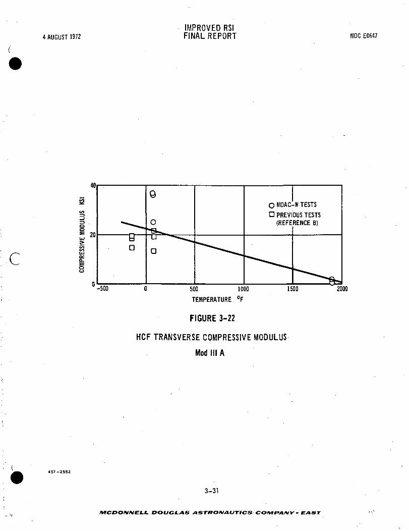
4 AUGUST 1972IMPROVED RSIFINAL REPORT MDC E0647
£V)
c 01Cga.
I
O MDAC-W TESTS
D PREVIOUS TESTS(REFERENCE B)
0 500 1000
TEMPERATURE °F
FIGURE 3-22
HCF TRANSVERSE COMPRESSIVE MODULUS
Mod III A
1500 2000
3-31
/VTCDO/V/VC'f.C. DOUGLAS ASTRONAUTICS COMfAIVY • E AST

IMPROVED RSI4 AUGUST 1972 FINAL REPORT MDCE0647
MOD IIIA material from the Reference (b) program. Straight line least squares curve
fits are also shown. The curve for the longitudinal compression modulus, shown in
Figure 3-20, indicates that modulus increases with test temperature. This does not
seem reasonable and is therefore questionable. Other curves show both strength and
modulus decreasing with temperature. The large scatter in test results is charac-
teristic of brittle ceramics.
Strength Gradient Improvements - As discussed in Section 2.2, density gradients
were reduced and overall uniformity less improved; however, some HCF specimens which
were uniformly dense were still weak in the center of the felt. Therefore, causes
were identified and problem areas were isolated and the strength uniformity was
improved.
The problem was approached by attempting to obtain a more uniform felt compo-
sition. Two components of the HCF were suspected of not being uniformly distributed:
the binder and the hollow silica spheres. The binder was suspected because the sur-
faces were stronger than the center; this condition io characteristic of the
migration mechanism which occurs during the drying of this type of binder. .When
liquid migrates to the surface to evaporate, it carries with it some of the binder
solids phase which is then deposited near the surface. The hollow spheres in HCF
were considered to be a cause of nonuniformity because they could be seen floating
during the felting process when the felting time became excessive. Also, micro-
graphic examination revealed that the concentration of the spheres was higher near
the top surface in some cases.
Rapid Strength Screening Test - Several techniques were investigated for
quickly measuring the strength uality of HCF material. (See Figure 3-23.) Such
subjective techniques as simply observing, squeezing, and rubbing the material may
be satisfactory for determining variations across the surface area of a tile, but
they are not adequate in quantitizing differences from tile to tile. The most
3-32
LL DOUGLAS ASTRONAUTICS' COMf>AHY - EAST

IMPROVED RSI4 AUGUST 1972 FINAL REPORT MDCE0647
promising method evaluated for providing a rapid, quantitative indication of
strength was a free falling sphere impact indentation test.
The impact indentation test (Figure 3-24) utilizes a dial micrometer with an 85-
gram load and a 0.25-inch ball tip (per ASTM D395, method B) to measure the specimen
thickness before and after a glass sphere impacts the surface of the HCF. A glass
sphere with a weight of 5.05 grams and a diameter of 0.616 inch is dropped through
a tube from a height of 25.4 inches onto the HCF specimen. The measurement of the
depth of the impact depression (in mils) is reported as the impact indentation
number. A range of acceptable impact indentation numbers was established,
based on observation and strength data:
Impact Indentation (Mils) Remarks
20-30 Very Strong
30-40 Strong
40-50 Fair
50-60 Barely acceptable
60 and above Weak
3-33
MCDONNELL. DOUGLAS ASTRONAUTICS : COMfANY • EAST

4 AUGUST 1972IMPROVED RSIFINAL REPORT MDC ECS47
~v
METHOD
(1) VISUAL AND PHYSICALOBSERVATION
(2) IMPACT INDENTATIONTEST
(3) TENSILE/COMPRESSIVESTRENGTH TESTS
(4) X-RAY
PROS
FAST, SLIGHT VARIATIONS INTILE SEEN
RELIABLY CALIBRATED, REPRO-DUCIBLE, FAST
ACCURATE MEASURE OFSTRENGTH, REPRODUCIBLE
CAN DETECT GRAIN, DENSEINCLUSIONS, VOIDS, LARGE AREAVISIBLE
CONS
SUBJECT TO OBSERVER ERROR, NON-REPRODUCIBLE
NOT DIRECT MEASURE OF STRENGTH, CHECK ONLYSMALL AREA
SLOW, CHECKS ONLY SMALL AREA
SLOW, NEED 2 VIEWS TO ACCURATELY LOCATE DEFECTSEDGE AFFECT DISTORTION. CANNOT PROVIDE ESTIMATEOF STRENGTH
FIGURE 3-23
HCF QUALITY MEASUREMENT METHODS
DIAL MICROMETER
SPECIFICATIONS:
• LOAD =85 GRAMS• TIP =0.25 INCH
BALL
1 1 /""^r
/
i
r-T
I/
25.
/,
UBE
— PIN
i
UN.
y — GLASS SPHERE SPECIFICATIONS:/ • WEIGHT = 5.05 GRAMS
• DIAMETER = 0.616 INCH
>*Hw^
457-2437
FIGURE 3-24
HCF IMPACT HARDNESS TEST DEVICE
3-34
MCDONNELL DOUGLAS ASTRONAUTICS COMPANY • EAST

IMPROVED-RSI4AUGUST1972 FINAL REPORT MDCE0647
3.3 THERMAL PROPERTIES - The thermal properties improvement of candidate
HCF formulations was measured by thermal shock tests using the oxyacetylene torch
and by thermal performance tests using radiant graphite heaters.
Thermal Shock Testing - Mullite HCF specimens with four candidate binders
were exposed to the calibrated oxyacetylene torch simulating the chock obtained
from plasma jet testing performed at NASA centers where a large thermal gradient
in the surface plane and rapid heat-up and cool-down were experienced. The speci-
mens were held at 2300°F for 5 minutes during each cycle.
Specimens made with RSB-1 (silicate binder) survived 6 to 9 cycles before
cracking, while RSB-2 (silica binder) specimens lasted 17 to 19 cycles before
cracking. While RSB-3 (mullite binder) specimens lasted 30 cycles before testing
was terminated, they had very low measured strength values. RSB-4 (alumina binder)
specimens failed after 9 cycles.
^~ Thermal Performance Testing - Candidate materials were tested and ranked
according to performance, and an effective thermal conductivity was computed for
comparison with guarded hot plate measurements which indicated an additional mode
of heat transfer through RSI, probably direct short wavelength radiation. In this
section, details of the thermal performance testing and a comparison of effective
and guarded hot plate conductivities are discussed.
To determine if a candidate HCF formulation had improved performance, a com-
parative test method was established and used in which seven 3.3-inch diameter
specimens were exposed to the same environment at one time. The heat source was
a radiant graphite heater, which heats a coated columbium susceptor plate (21.5
by 21.5 inches) which in turn heats the seven HCF specimens. It was employed for
these tests because of its heat flux uniformity at atmospheric as well as at reduced
pressure. The test specimen consisted of a disk of HCF bonded to a honeycomb backup
(' •structure. Thermocouples were installed at intervals through the test specimen for
3-35
MCDOIVtVELL DOUGLAS ASTRONAUTICS COMFV1/VV • EAST '"

4 AUGUST 1972IMPROVED RSIFINAL REPORT MDCE0647
THERMOCOUPLELEAD ORIENTATION
0.8 EMITTANCECOATING
HCF
3.3 IN. DIAMETER
Pt- 10% Rh SURFACE THERMOCOUPLE
FOUR IN-DEPTH THERMOCOUPLES
I I ONE BONDLINE THERMOCOUPLEFIBERGLASS HONEYCOMB
4S7-Z440
X-RAY PLAN VIEW X-RAY SIDE VIEW
(SPECIMEN 101-2)
FIGURE 3-25COMPARATIVE THERMAL PERFORMANCE TEST SPECIMEN
3-36
MCDONNELL DOUGLAS ASTRONAUTICS COMPANY • EAST

4 AUGUST 1972
IMPROVED RSIFINAL REPORT MOC E0647
c
. ./.
457-2441 FIGURE 3-26THERMAL PERFORMANCE TEST SPECIMENS MOUNTED IN SPECIMEN HOLDER
3-37
AfGOO/V/VE-f.1. DOUGLAS ASTRONAUTICS COn*r*A*IY • EAST

4 AUGUST 1972
IMPROVED RSiFINAL REPORT MDC E0647
.'3
. RADIANT HEATER TESTS
.ATMOSPHERIC AND REDUCEDPRESSURE
. TEST FIXTURE OVER HEATER
. DIRECT COMPARISON BETWEENSEVEN SPECIMENS IN SAMETEST
FIGURE 3-27
OPACIFIED HCF - THERMAL PERFORMANCE TESTS
" ~* -'• ^ ' •^"''M^T' ranis I1" ' s- *~"T7r K ''*- -•--'• •>' - i:****---!
•' l-B' ^^^>4h--^=*-~•• .v.l-ipi^^^ -?%^\^=^. VYV!JW-1:'3E-J . JfX->-«'A -^•-.:
i ^S^s^^^ f- S^
L- • '',>'- • •££~(~\4*} 3
S$£r -PTWli Wn^vxLir'' :1^ • \\(. . _^ fc ;J._ •' •• .--r|- j ,-<•„ j •• .•S.-'h-~»j
• - - i- V^. '^^i <V ——
FIGURE 3-28
HCF TEST FIXTURES IN SPACE CHAMBER
3-38
/VfCDO/V/VEUL DOUGLAS ASTRONAUTICS COIYIF»AHY - EAST
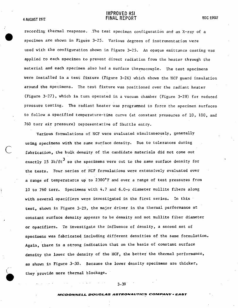
IMPROVED RSI4 AUGUST 1972 FINAL REPORT MDCE0647
recording thermal response. .The test specimen configuration and an X-ray of a
specimen are shown in Figure 3-25. Various degrees of instrumentation were
used with the configuration shown in Figure 3-25. An opaque emittance coating was
applied to each specimen to prevent direct radiation from the heater through the
material and each specimen also had a surface thermocouple. The test specimens
were installed in a test fixture (Figure 3-26) which shows the HCF guard insulation
around the specimens. The test fixture was positioned over the radiant heater
(Figure 3<-27) , which in turn operated in a vacuum chamber (Figure 3-28) for reduced
pressure testing. The radiant heater was programmed to force the specimen surfaces
to follow a specified temperature-time curve (at constant pressures of 10, 100, and
760 torr air pressure) representative of Shuttle entry.
Various formulations of HCF were evaluated simultaneously, generally
using specimens with the same surface density. Due to tolerances during
c—" fabrication, the bulk density of the candidate materials did not come out3
exactly 15 Ib/ft so the specimens were cut to the same surface density for
the tests. Four series of HCF formulations were extensively evaluated over
a range of temperatures up to 2300°F and over a range of test pressures from
10 to 760 torr. Specimens with 4.7 and 6.0-y diameter mullite fibers along
with several opacifiers were investigated in the first series. In this
test, shown in Figure 3-29, the major driver in the thermal performance at
constant surface density appears to be density and not mullite fiber diameter
or opacifiers. To investigate the influence of density, a second set of
specimens was fabricated including different densities of the same formulation.
Again, there is a strong indication that on the basis of constant surface
density the lower the density of the HCF, the better the thermal performance,
as shown in Figure 3-30. Because the lower density specimens are thicker,i
they provide more thermal blockage.
- 3-39
MCDONNELL DOUGLAS ASTRONAUTICS CO/Vf*»A/VV • EXIST

I AUGUST 1972IMPROVED RS!FINAL REPORT MOC E0647
10
457-14*6
760 TORR100 TORR10 TORR
100TEST PRESSURE - TQRR
1000
TESTTEMPERATUREPROFILE
400TIME - SEC
FIBERDIAMETER
(M)
4.7
4.7
6
6
4.7
4.7
OPACIFIER
3% ZIRCON
NONE
NONE
3Ui02
1% ZIRCON
3% ZIRCON
FILLER
CENO-SPHERESCENO-SPHERESECCO-SPHERESECCO-SPHERESECCO-SPHERES
ECCO-SPHERES
DENSITY(pen
17.71
15.04
15.67
14.93
14.74
13.87
SAMPLE
49-12(MOO II)
47-2
37-1— C(STANDARD)123-B(MOD 1)
41-1-A
41-2-A(MOD III)
SAMPLE SURFACE DENSITY = 1.3 PSF LB/FT21 0.01 LB/FT2
HCF SPECIMEN DENSITYHAS GREATEST INFLUENCEON THERMAL PERFORMANCE
FIGURE 3-29
DECREASED HCF DENSITY IMPROVES THERMAL PERFORMANCE FORCONSTANT SURFACE DENSITY USING VARYING FORMULATIONS
3-40
MCDONNELL DOUGLAS ASTRONAUTICS COMPANY • EAST

4 AUGUST 1972IMPROVED RSIFINAL REPORT MDC E0647
c457-2533
400 EDO 800 1000
SPECIMEN NO.
— 69-5
— 53-7
— 257-A
— 53-6
^-53-8
^—53-5
— 69-2
FIBERDIAMETER
(»)
4.7
4.7
6.0
4.7
4.7
4.7
4.7
FILLER
ECCOSPHERES
ECCOSPHERES
ECCOSPHERES
CENOSPHERES
ECCOSPHERES
CENOSPHERES
ECCOSPHERES
OPACIFIER
3% ZIRCON
3% ZIRCON
3% Ti02
3% ZIRCON
3% ZIRCON
3% ZIRCON
3% ZIRCON
DENSITY(LB/FT3)
13.15
14.41
15.29
14.75
15.03
14.97
17.31
SURFACE DENSITY =
TEST PRESSURE-TORR1000
FIGURE 3-30
DECREASED HCF DENSITY IMPROVES THERMAL PERFORMANCEFOR CONSTANT SURFACE DENSITY USING VARYING FORMULATION
Figure 3-31 shows the results of testing a set of specimens of identical
composition, but varying bulk density and surface density. To separate actual
density effects from those resulting from increased or decreased HCF thickness,
the specimens were cut to the same thickness; and surface density was, therefore,
not constant among specimens. In general, the results indicate that (for
constant HCF thickness) higher density specimens perform better. The trend,
however, is not conclusive; it has a large amount or" scatter.
Effective thermal conductivities for MOD IIIA were calculated using
the measured temperature histories of the heated surface and of the bondline
3-41 ,
MCDONMELL. DOUGLAS ASTRONAUTICS COMfANY - EAST

IMPROVED RSI4 AUGUST 1972 FINAL REPORT MDCE0647
as the boundary conditions for a thermal model. The thermal conductivity curve
(a function of temperature) was adjusted to produce computed temperature
histories for all the thermocouples throughout the specimen that best correlated
with the measured response by producing the smallest least-squares error. This
procedure was employed for the three test pressures and the resulting effective
conductivity is compared with the guarded hot plate data in Figure 3-32. Similar
results were obtained for arc tunnel and radiant heater tests using the Thermal
Property Analyzer Computer Method. For these tests it can be concluded that
an additional mechanism of heat transfer exists within RSI other than conduction
measured by the guarded hot plate device.
A fourth test was conducted using mullite specimens with the addition of fine
fibers, opacifiers and with the deletion of the normal silica spheres. (See Figure
3-33.) The addition of fine silica fibers appeared to improve the thermal perfor-">• •
mance of mullite HCF as indicated by specimen B103-1 (MOD V type), compared with
the baseline MOD IIIA specimens.
These test results agree with the Reference (a) work, which showed that the
radiant heat transfer in 6-y diameter mullite fibers is considerably higher
than 2.5-y diameter fibers of the same chemical composition. The Reference (a)
work found this same relationship using silica fibers of two different diameters.
3-42
/VTCDO/V/VEXL. DOUGLAS ASTKOAIAUTICS CO/tfFVa/VV • EAST

4 AUGUST 1972IMPROVED RSIFINAL REPORT MDC EOS47
cotuI
u_.?D
troLU
Ooaoeou_oui
soc
• MOD III HCF:;4.7-u MULLITE FIBERS, ZIRCON OPACIFIERECCOSPHERE FILLER, THICKNESS = 1.5 INCHESPRODUCTION-MAGNITUDE DENSITY GRADIENTS
SPECIMEN NO.
296C3174
SYMBOL
0aAD0O
^
DENSITY LB/FT3
15.6516.7013.9014.9914.0013.3012.84
LOCATION OF DENSERSURFACE
HEATED SURFACEBONOLINEBONDLINEBONDLINEBONDLINEBONDLINEHEATED SURFACE
55010
4S7-2538
50 100TEST PRESSURE - TORR
FIGURE 3-31
EFFECT OF DENSITY ON HCF THERMAL PERFORMANCEUSING CONSTANT FORMULATION
— - - - - - 3-43
MCDONMELL. DOUGLAS ASTRONAUTICS COIVIfANY • EAST

4 AUGUST 1972
o u.
3 tUJ
3.0
2.0
1.0
IMPROVED RSIFINAL REPORT
10 TORR
0 400 800 1200 1600 2000 2400
TEMPERATURE - °F
MDC E0647
100 TORR
457-2161
i>-
o u_
CO
i>-
o u_E .-•
3.0
2.0
1.0
0 400 800 1200 1600 2000 2400
TEMPERATURE - °F
760 TORR
CO
0 400 800 1200 1600 2000 2400
.TEMPERATURE - °F
EFFECTIVE THERMAL CONDUCTIVITYGUARDED HOT PLATE DERIVED DERIVED FROM PERFORMANCE TESTINGTHERMAL CONDUCTIVITIES • "CF DENSITY = LB/FT3
• HCF Cp = 0.25 BTUAB-°F
FIGURE 3-32
EFFECT OF PRESSURE ON THERMAL CONDUCTIVITY
3-44
DOUGLAS ASTRONAUTICS COMPANY • EAST
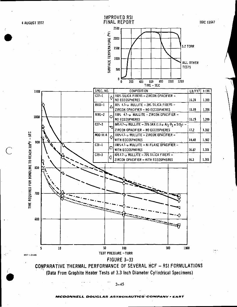
4 AUGUST 1972
1100
1000
oUJ
900
cUJo:o
UJ
z 800o
mCEoU-oUJ
I 700oUJ
600
IMPROVED RSIFINAL REPORT filDC E0647
13UU
uT<a_o?3
S: ison5 13W
Q_
UJi — inoftUJo
| 50000
n
/
J
,
/
^
V\
1"N
\
X
5.2 TORR
ALL OTHERTESTS
200 400 600 800TIME - SEC
1000 1200
SPEC. NO.
C37-1
B103-1
B101-2
C37-3
MOD III A
COMPOSITION
100% SILICA FIBERS - ZIRCON OPACIFIER -NO ECCOSPHERES80% 4.7-n MULLITE -20% SILICA. FIBERS -
ZIRCON OPACIFIER - NO ECCOSPHERES
100% 4.7-n MULLITE -ZIRCON OPACIFIER
NO ECCOSPHERES
LB/FT?
16.28
15.59
15.1980%4.7-u MULLITE - 20% SKX (1.6 n AI2 03
ZIRCON OPACIFIER - NO ECCOSPHERES
100%4.7-u MULLITE - ZIRCON OPACIFIER -
WITH ECCOSPHERES
100%4.7-p MULLITE - Ni FLAKE OPACIFIER -
WITH ECCOSPHERES
20% SILICA FIBERS -
WITH ECCOSPHERES
17.2
14.48
16.87
16.3
h(IN)
1.300
1.398
1.399
1.302
1.502
1.301
1.365
50 100
<6 TEST PRESSURE-TORR
FIGURE 3-33COMPARATIVE THERMAL PERFORMANCE OF SEVERAL HCF - RSI FORMULATIONS
(Data From Graphite Heater Tests of 3.3 Inch Diameter Cylindrical Specimens)
DOUGLAS ASTBOHIAUTICS- CO/Wf»/»/VV • EAST

IMPROVED RSI4 AUGUST 1972 FINAL REPORT MDCE0647 ,/l
4.0 COATING DEVELOPMENT
Prior to this program, a liquid waterproof high emittance inorganic coating
system, designated M25A7, was developed for the mullite HCF. This was a multi-
layered, gradated density coating which was successfully scaled up and tested on
6 by 6 by 1.5-inch and 12 by 12 by 1.5-inch tiles.
In this and in the concurrent MSC program (Reference (b)), new concepts were
investigated to improve the reusable liquid waterproof coating (glass sealed).
The basic problem with a glassy coating is cracking due to: (1) high thermal
stresses in the coating caused by thermal gradients during entry heating; and (2)
residual stresses in the coating resulting from differential thermal expansion of
the coating relative to the HCF.
Factors which aggravate this cracking tendency are:
a. increased tile thickness,
( b. inorganic coating on five sides of a tile,
c. variations in insulation material strength,
d. nonuniform surface texture of the HCF material.
During this program and related programs, the following methods were used to
evaluate the high temperature resistance of the HCF coatings:
a. screening of coatings applied to 2 by 2 by 1/2-inch HCF coupons using an
oxyacetylene torch,
b. application of the coatings to full-size tiles for testing in the graphite
heater or quartz lamps,
c. thermal expansion measurements,
d. low pressure tests in the graphite heater.
The major tasks to reduce cracking of the coating which were performed in
each respective program were:
4-1
MCDOMMELL DOUGLAS ASTKOIVAUTICS COMPANY • EAST

IMPROVED RSI4 AUGUST 1972 FINAL REPORT MDCE0647
NASA-MSC
1. M25A7 Coating Improvements,
2. liquid waterproof coating development,
NASA-MSFC
1. reinforcement techniques in base coating,
2. grooves in coating,
3. nonglassy seal coatings,
MDAC-IN-HOUSE-EFFORT
1. one-step glassy coatings,
2. coating properties measurements.
4.1 COATING IMPROVEMENTS - A summary of early coating development work
performed on 2 by 2 by 1/2-inch HCF coupons is given in Figure 4-1. The main index
of improvement was thermal shock resistance determined by using the oxyacetylene
torch to rapidly heat the surface. A maximum test temperature of 2300°F was main-
tained over a 5-minute period to complete the test cycle. The M25A7 coated
Phase I Mullite HCF was used as a standard for gaging improvement.
During this phase of the work, the coating weight was reduced by eliminating
the "intermediate coating" in the M25A7 coating system. Improved coating texture
resulted from a smoother base coating. The thermal expansion of the base coating
was measured and was found to closely match that of the mullite HCF; and changing
the expansion coefficient of the base coating did not improve the thermal cycling
resistance of the coating. Reducing the base coating modulus did not improve the
thermal shock resistance because more glass sealer was required to obtain a water-
proof coating.
The current trend of the development work has b~een toward the one-step coatings
which offer potential weight and cost improvements over the multistep coatings
(M25A7, MMpP7). The basic structure of the multistep coatings compared with the
4-2
DOUGLAS ASTRONAUTICS COMfAIVY • EAST :
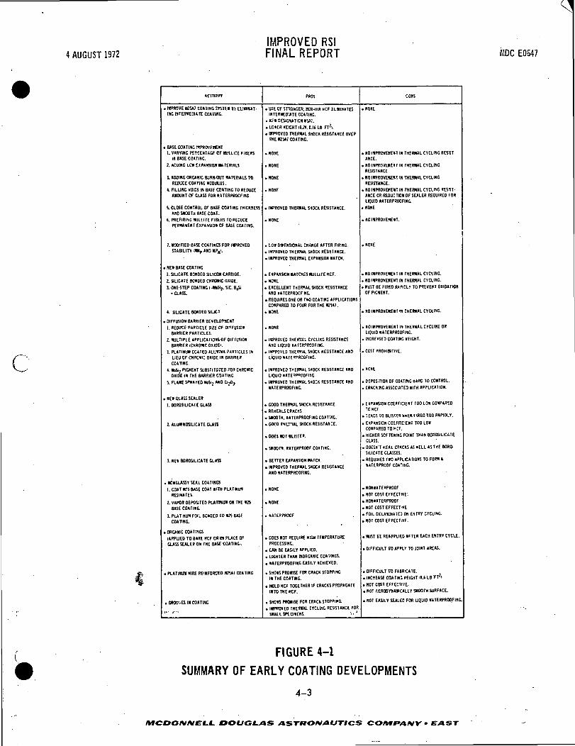
4 AUGUST 1972IMPROVED RSIFINAL REPORT MDC E0547
c
Acnvin
. MPROVE MB5AI COATING SYSTEM 91 EL1M»»1-inG INTERMEDIATE COATOG.
. BASE COATING IMPROVEMENT1. VARYING PERCENTAGE OF MULLITE FIBERS
III BASE COATING.
2. ADDING LOU EXPANSION MATERIALS
1 ADOIHC ORGANIC BURH-OUT MATERIALS TOREDUCE COATING "OOIH-US.
1. FILUNG VOIDS IN BASE COATING TO REDUCEAMOUNT OF GLASS FOR tATERPROOFING.
S. CLOSE CONTROL OF BASE COATING WCKNESSAND SMOOTH BASE CDAT.
6. PREFIRING MULLITE FIBERS TO REDUCEPERMANENT EXPANSION OF BASE COATING.
T. MODIFIED BASE COATINGS FOR IMPROVEDSTABILITY IMMp AND •?£*.
• NEI BASE COATING
1. SILICATE BONDED SILICON CARBIDE.
2. SILICATE BONDED CHROtlC OXIDE.
1. ONE-STEP COATING I-«SS<?. SiC. 6,5.• CLASS.
< SILICATE BONDED SILICA
. DIFFUSION BARRIER DEVELOPMENT
1. REDUCE PARTICLE Ml OF DIFFUSIONBARRIER PARTICLES.
2. «ULT1PLE APPLICATIONS OF DIFFUSIONBARRIER tCHROMC OXKJE'.
3. PLAT1NU1I COATED ALUKNA PARTICLES INLIEU OF CHROMIC OXIDE IN BARRIERCOATING.
1. MoSti PIGMENT SUBSTITUTED FOR CHROMICOHIOEIN THE BARRIER COATING.
S. FLAME SPRAYED KoS>2 »»0 CtjOj.
. NE» CLASS SEALER
1. BOROSIUCATE GLASS
2. ALUMWOSILICATE CLASS
3. NEI BOROSILICATE GLASS
. NDNGLASST SEAL COATINGS
1. COAT M2S BASE COAT WITH PUTINU»RESINATES.
2. VAPOR DEPOSITED PLATBUM ON THE »25BASE COATING.
!. PLATINUM FOIL BONDED 10 M2i BASECOATING.
. ORGANIC COA7I1GS
lAPPUEO TO BARE HCF OH 01 PUCE OFGLASS SEALER ON THE BAS£ COATINGi.
. PLATINUM "IRE REINFORCED M2SAJ COATING
. GROO'.tS III COATING
,.. ,...
PROS
• USE OF STRONGER, MOD-IIIA HCF ELIMINATESINTERMEDIATE COATING.
.KEI DESIGNATION ««1.
.LOWER WEIGHT 10.24. (US LB FTZI.
. IMPROVED THERMAL SHOCK RESISTANCE OVERTHE M2SAJ COATING.
.NONE
.NONE
.NONE
.HONE
. IMPROVED THER1UL SHOCK RESISTANCE.
. NONE
. LOW DIMENSIONAL CHANGE AFTER FIRING.
. IMPROVED THERMAL SHOCK RESISTANCE.
. IMPROVED THERMAL EXPANSION MATCH.
. EXPANSION MATCHES MULLITE HCF.
.NONE
. EXCELLENT THERMAL SHOCK RESISTANCEAND IATERPROOFING.
. REQUIRES ONE OR TWO COATING APPLICATIONSCOMPARED TO FOUR FOR THE M2SA1 .
.NONE
. NONE
• IMPROVED THER*«AL CYCLING RESISTANCEAND LIQUID WATERPROOFING.
. IMPROVED THERMAL SHOCK RESISTANCE ANDLIQUID WATERPROOFING.
. IMPROVED THERMAL SHOCK RESISTANCE ANDLIQUID WATERPROOFING
. IMPROVED THERMAL SHOCK RESISTANCE ANDWATERPROOFING.
. GOOD THERMAL SHOCK RESISTANCE.
• REHEALS CRACKS
. SMOOTH. WATERPROOFING COATING.
. GOOD IHLTUL SHOCK RESISTANCE.
. DOES NOT BUSTER.
• SMOOTH. WATERPROOF COATING.
. BETTER EXPANSION HATCH.
. IMPROVED THERMAL SHOCK RESISTANCEAND WATERPROOFING.
.NONE
.NONE
. WATERPROOF
. DOES NOT REQUIRE HIGH TEMPERATUREPROCESSING.
. CM BE EASILY APPLIED.
. LIGHTER THAN INORGANIC COATINGS.
. WATERPROOFING EASILY ACHIEVED.
. SHOWS PROMISE FOR CRACK STOPPINGIN THE COATOIC.
. HOLD HCF TOGETHER IF CRACKS PROPAGATEINTO THE HCF.
. SHOB PROMISE FOR CRACK STOPPING.
. IMPROVED THERMAL CYCLING RESISTANCE FORSHALL SPECIMENS. '••'
CONS
.NONE
• NO IMPROVEMENT IN THERMAL CYCLING RESIST-ANCE.
. NO IMPROVEMENT IK THERMAL CYCLINGRESISTANCE.
. NO IMPROVEMENT IN THERMAL CYCLINGRESISTANCE.
. NO IMPROVEMENT IN THERMAL CYCLING RESIST-ANCE OR REDUCTION OF SEALER REQUIRED FORLIQUID WATERPROOFING.
. NONE
. NO IMPROVEMENT.
1
.NONE
. NO IMPROVEMENT IN THERMAL CYCLING.
. NO IMPROVEMENT IN THERJWL CYCLING.
. MUST BE FIRED RAPIDLY TO PREVENT OXIDATIONOF PIGMENT.
. NO IMPROVEMENT IN THERMAL CYCLING.
. NO IMPROVEMENT IN THERMAL CYCLING ORLIQUID WATERPROOFING.
. INCREASED COATING WEIGHT.
. COST PROHIBITIVE.
.NONE
. DEPOSITION OF COATING HARD TO CONTROL.
. CRACKING ASSOCIATED WITH APPLICATION.
. EXPANSION COEFFICIENT TOO LOW COMPAREDTO HCF.
. TENDS TO BLISTER «MENFIREO TOO RAPIDLY.
. EXPANSION COEFFICIENT TOO LOWCOMPARED TO HCF.
. HIGHER SOFTENING POINT THAN BOROSILICATEGLASS.
. OOESH'T HEAL CRACKS AS WELL AS THE BORO-SILICATE GLASSES.
. REQUIRES TWO APPLICATIONS TO FORM AWATERPROOF COATING.
. NONWATERPROOF
.NOT COST EFFECTIVE.
. NONWATERPROOF
. NOT COST EFFECTIVE
. FOIL DELAMINATED ON ENTRY CYCLING.
. NOT COST EFFECTIVE.
. MUST BE REAPPLIED AFTER EACH ENTRY CYCLE.
. DIFFICULT TO APPLY TO JOINT AREAS.
. DIFFICULT TO FABRICATE.
. INCREASE COATING WEIGHT O.t LB 'FT!I
. NOT COST EFFECTIVE.
. NOT f.EROOVNAIICALLY SMOOTH SURFACE.
. NOT EASILY SEALED FOR LIQUID WATERPROOFING.
FIGURE 4-1
SUMMARY OF EARLY COATING DEVELOPMENTS
4-3
MCDONNELL DOUGLAS ASTRONAUTICS CO/tffVl/VK - £ AST
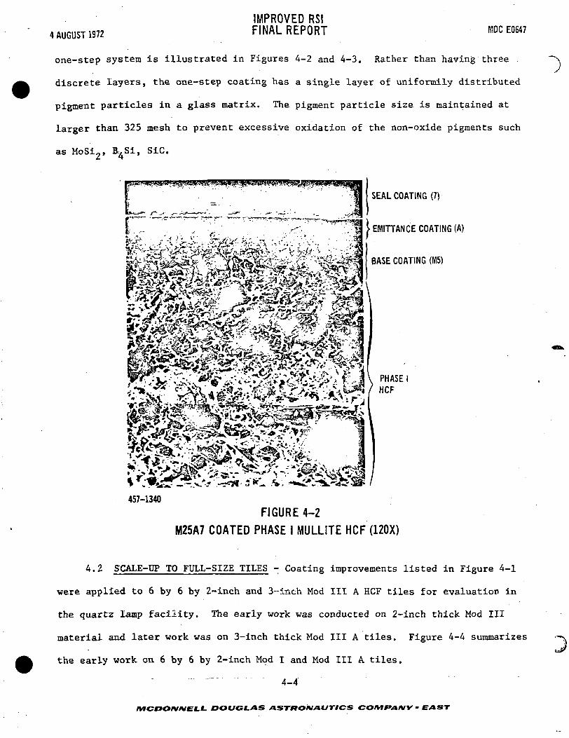
IMPROVED RSIFINAL REPORT MDC E06474 AUGUST 1972
one-step system is illustrated in Figures 4-2 and 4-3. Rather than having three
discrete layers, the one-step coating has a single layer of uniformily distributed
pigment particles in a glass matrix. The pigment particle size is maintained at
larger than 325 mesh to prevent excessive oxidation of the non-oxide pigments such
as MoSi2, B^Si, SiC.
SEAL COATING (7)
EMITTANCE COATING (A)
BASE COATING (M5)
PHASE IHCF
457-1340
FIGURE 4-2M25A7 COATED PHASE I MULLITE HCF (120X)
4.2 SCALE-UP TO FULL-SIZE TILES - Coating improvements listed in Figure 4-1
were applied to 6 by 6 by 2-inch and 3--inch Mod III A HCF tiles for evaluation in
the quartz lamp facility. The early work was conducted on 2-inch thick Mod III
material and later work was on 3-inch thick Mod III A tiles. Figure 4-4 summarizes
the early work on 6 by 6 by 2-inch Mod I and Mod III A tiles.
" 4-4
\
/VfOOO/V/WEf.L DOUGLAS ASTKOMAUTICS COMfAMY' • EAST

4 AUGUST 1972
IMPROVED RSIFINAL REPORT MDC EOS47
457-2442
.v
jtt *c*lv • v **.••• -"SSi X$&&-'-$m•^<s±&'-S3aif • '•:. *f* ?aSr»iL «.H
^ ;, tl-if-.--, -Vs;* ^ is^<^-vj**ai ' 1^x>^-^\j* >^». '' w;:- ,S^rN .,--JS^M '-S^if i^-T ' -:^V-^^V^^P^4»!^te^^fc^^M4ieiai^^
ONE-STEP COATING (Mo7)
MOD IIIA HCF
FIGURE 4-3
Mo7 COATED MOD IIIA MULLITE HCF (100X)TESTED 20 CYCLES AT 2500°F IN TORCH
The tiles,, equipment and test setup are shown in the following figures. The three
basic configurations of test tiles are shown in Figure 4-5. HCF tiles were usually
2 or 3-ineh thick and were coated on 5 sides or on 1 surface only, as pictured.
These tiles were bonded with RTV-560 silicone adhesive to titanium with a 1/4-inch
thick silicone sponge layer for strain isolation. A "Data Trak" Controller
(Figure 4-6) programmed the power input to the quartz lamps shown in Figures 4-7
and 4-8. The surface temperatures on the specimen and the bondline temperatures
~ " 4-5
!_£. DOUGLAS ASTRONAUTICS CO/tf f/I/VK • EAST

4 AUGUST 1972
IMPROVED RSIFINAL REPORT MDC E0647
COATING
(top only)
(top only)
(5 sides)
M523A7056
(top only)
M523A7056
(5 sides)
M523A7
(5 sides)
MMpP7
COATING
LB/FT2
0.190
0.200
0.185
0.218
0.200
0.180
0.145
NO. OF CYCLESAT 2300°F
30 (wp)*
30 (wp)
30(wp-20 eyeSWP-25 eye)
30 (wp)
30 (wp)
30 (wp)
30 (wp)
COMMENTS
Slight blistering on coating after10 cycles, single small crack notedon one edge (uncoated) after 10 cycles.
Few secondary bubbles in glass after20 cycles. No cracks noted.
Slight blistering on coating after5 cycles. No cracks noted.
No blistering, slight crack onone side (uncoated)
Slight crack on edge and top oftile. No blistering.
Moderate blistering. No cracks.
No blisters, no cracks.
(wp) = waterproof
FIGURE 4-4FULL SCALE COATING IMPROVEMENT TEST RESULTS
Note: All HCF tiles were bonded to titanium (.03-inch) plate with RTV-560silicone adhesive and a 1/4-inch thick strain isolation siliconesponge insert.
were plotted as a function of time on the recorder (Figure 4-9). The same time/
temperature entry profile (Section 5.2) used in the low pressure tests which
describes the predicted surface temperature history on one area of the Shuttle
Orbiter was used. Figures 4-10, 4-11, and 4-12 show the HCF tile in place in the
quartz lamp test fixture before, during and after testing, respectively. Glass
sealed 6 by 6-inch HCF tiles have been cycled up to 100 times using this facility.
The standard M5~_A7 coating which uses a phosphate bonded chromium oxide (A)
emittance coating tends to blister to various degrees as a result of heating
4-6
MCDONMELL. DOUGLAS ASTRONAUTICS - EAST

4 AUGUST 1972IMPROVED RSIFINAL REPORT MDC E0647
\ r~
r
\- 'O.UJ .
IfCM
.-**
-^m
;o•Q-o
x
,IO
OUJ0.
»-UJI-o_s
m j
4- MUJ ^S5 <1 Si*- u.
o
oo
4-7
MCDOfVfVELL DOUGLAS ASTRONAUTICS COMf*AIVY - EAST

4 AUGUST 1972
IMPROVED RSIFINAL REPORT MDC E0647
» V
F^
B
11
%
.)
i a • *
e .*_•*'"*e*
FIGURE 4-6
QUARTZ LAMP CONTROLLER BANK
I S %*» ^ _ .A^-^gj^A-tftiUia^l^«^.-> Zf t^' '
:r " =-lj5S ELEMENTS
FIGURE 4-7
FRONT VIEW OF QUARTZ LAMPBANK SHOWING ELEMENTS
FIGURE 4-8
REAR VIEW OF QUARTZ LAMP BANKSHOWING WATER-COOLED REFLECTOR
'• *-V-"-:"-"»t':«"."''.* '-M- o I ; • < i e ) » s u -4 • ' •'•'-- r,L__4- 0 I 2 3 4 5 6 1 ! 9 10 .
: A
T^J-JJ'»^-.'«:*W!!t'';ri*«*| ;-| . p^ii^fjjsijijjs^^ ^IH I ^jg
j 'j^g^g?y?fe= '•" •••iBMhiiiViiig'j
^a^
FIGURE 4-9
QUARTZ LAMP RECORDER BANK
4-8
DOUGLAS ASTRONAUTICS CO/VtfXt/W - EAST
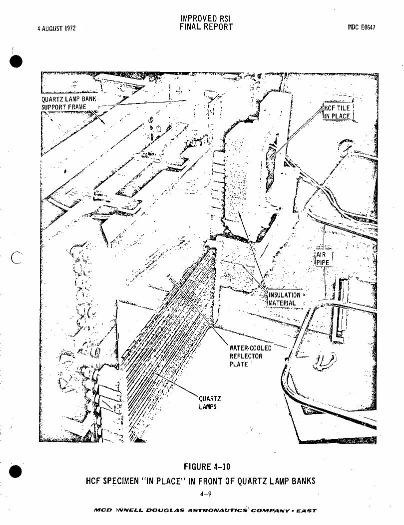
4 AUGUST 1972IMPROVED RSIFINAL REPORT MDC E0647
c
QUARTZ LAMP BANKSUPPORT FRAME
-*= ^INSULATION"1 MATERIAL
WATER-COOLEDREFLECTORPLATE
FIGURE 4-10
HCF SPECIMEN "IN PLACE" IN FRONT OF QUARTZ LAMP BANKS4-9
MCD W/VE-JLJL. I7OOCf-/4S ASTRONAUTICS COMfAIW • EAST

4 AUGUST 1972IMPROVED RS!FINAL REPORT MDC E0647
FIGURE 4-11
HCF TILE "IN PLACE" DURING HEAT-UP PHASE OF TEST(Insulation Removed)
451-2377
ibi *?'•' ~ -:gfy&*j ~-"K••"3 / • •"•• ' - ' ' • " • - • '
FIGURE 4-12
HCF TILE AFTER TEST WITH INSULATION PARTIALLY REMOVED4-10
MCDONNELL. DOUGLAS >ISTf7OM/lCSTYCS COMfANY - EAST

IMPROVED RSI4 AUGUST 1972 FINAL REPORT MDCEOS47
above 2300°F. The MS-.,?? coatings, with a silicate bonded chromium oxide (P)
emittance coating, showed a marked improvement in blister reduction. The M52_A7
did not blister using a different borosilicate glass, but two coats were required
to waterproof the tiles. The MM P7 coated tile did not blister or crack and wasP
tested to a total of 100 cycles in the quartz lamps without failure or loss of
waterproofing.
The next step was to scale-up the most improved coatings to 3 and 3.5-inch
thick tiles. Early attempts to increase HCF tile thickness resulted in tile
failure which occurred in two basic modest The first mode was cracking or
delamination of the basic HCF material due to strength and density gradients
through the tile thickness and the second mode was cracking of the coating on
the top and sides of the tile due to the high thermal stresses in the coating.
Typical locations of these cracks are shown in Figure 4-13. Poor strength HCF
tends to propagate cracks which initiate in the coating. The cracks arising in
the coating are mainly a result of the stresses induced by thermal gradients across
the tile thickness. Slots, machined in the coating* stop cracks and provide stress
relieving mechanisms for the coating. Tiles have been tested with slots cut on the
sides in parallel and orthogonal grid patterns. Cracks did not propagate across
the slots but, in some cases, did run along the slots in the HCF material. The
overall cracking was greatly reduced by the slots.
Further scale-up work included the coating of full-size tiles which were
bonded to a copper support plate and to a titanium 1/2-size panel. The copper
support plate, shown in Figure 4-14, was tested in the graphite heater facility
shown in Figure 4-15. The specimens, positioned face-down on top of the heater
elements are shown in Figure 4-15. The test results (for the titanium 1/2-size
panel), shown in Figure 4-16, show the relative stability of coatings in a low
pressure (10-torr air) environment. The MoSi,,/Borosilicate (Mo7) and SiC/
aluminosilicate coatings did not blister or react at 2300°F. The MMp P 7P™-
4-11
MCDONNELL DOUGLAS ASTRONAUTICS-COMfANY - EAST
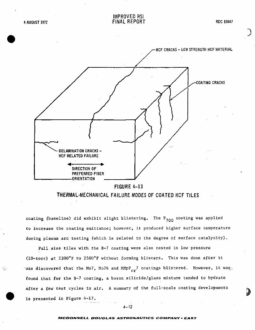
4 AUGUST 1972IMPROVED RSIFINAL REPORT MDC E0647
HCF CRACKS - LOW STRENGTH HCF MATERIAL
COATING CRACKS
-DELAMINATION CRACKS -HCF RELATED FAILURE
«4 *DIRECTION OFPREFERRED FIBER
: ORIENTATION
FIGURE 4-13
THERMAL-MECHANICAL FAILURE MODES OF COATED HCF TILES
coating (baseline) did exhibit slight blistering. The P70Q coating was applied
to increase the coating emittance; however, it produced higher surface temperature
during plasma arc testing (which is related to the degree of surface catalycity).
Full size tiles with the B-7 coating were also tested in low pressure
(10-torr) st 2300°F to 2500°F without forming blisters. This was done after it
was discovered that the Mo7, Mo76 and MMpP 7 coatings blist-ered. However, it was.
found that for the B-7 coating, a boron silicide/glass mixture tended to hydrate
after a few test cycles in air. A summary of the full-scale coating developments
is presented in Figure 4-17.
4-12
MCDONNELL. DOUGLAS ASTRONAUTICS COMPANY - EAST

4 AUGUST 1972IMPROVED RSIFINAL REPORT MDC E0647
r.
FIGURE 4-14
FULL SIZE TEST TILES BONDED TO COPPER SUPPORT PANEL
457-2573
4-13
MCDONNELL DOUGLAS ASTRONAUTICS COM&ANY • EAST

4 AUGUST 1972IMPROVED RS!FINAL REPORT MDC E0547
COLUMBIUM RADIATORPANEL
FIGURE 4-15
FULL SIZE PANELS IN POSITION ABOVE THE GRAPHITE HEATER
4S7-2574
4-14
MCDONNELL DOUGLAS ASTRONAUTICS COMPANY • EAST

4 AUGUST 1972IMPROVED RSIFINAL REPORT MDC EOS47
c
TILE NO.
B-67-2(DUMMY TILE)
409-1
409-3
425-1
442-2
445-1
445-2
445-3
COATING
MMS450-I5 SIDES COATED
™pPCr7P700
5 SIDES COATED
MIVIp SiC/1717
5 SIDES COATED
2 SiC/1717(1 COAT)5 SIDES COATED
2 Mo Si2/7740(1 COAT)(UNCOATED ON ONE END)
MNL SiC/17175 SIDES COATED
2 SiC/1717(1 COAT)5 SIDES COATED
2 Mo Si2/7740(1 COAT)5 SIDES COATED
TEST COMMENTS (EXAMINED AFTER:1 CYCLE AT 70% AREA 2P)
(1 CYCLE AT 90% AREA 2P)(4 CYCLES AT 100% AREA 2P)*
NO CHANGE, NOT W/P**
EMITTANCE OVERCOATING SPALLED EXTENSIVELY. W/PP700 DID NOT SPALL. SOME BLISTERS ON TOP. NOT W/PSPALLED AREA
WHEREON
COATING W/P. NO REACTION OR BLISTERING
COATING W/P. NO REACTION OR BLISTERING
COATED W/P. NO REACTION OR BLISTERING
COATING W/P. NO REACTION OR BLISTERING
NO CHANGE AFTER 4 - 2300°F CYCLES. NO REACTION ORBLISTERING
COATING W/P. NO REACTION OR BLISTERING
*70%-1500°FTMAX
** W/P-WATER PROOF
90% - 2000°F 100% - 2300°F
F I G U R E 4-16
TEST RESULTS ON TITANIUM 1/2 SIZEAREA 2P PANEL WITH 2.88 IN. THICK HCF
457-2529
4-15
MCDONNELL. DOUGLAS ASTRONAUTICS COMF»AfHV - EAST

4 AUGUST 1972IMPROVED RSIFINAL REPORT MDC E0647
t
I
COATING HCF TILE SIZE COMMENTS
M25A7
M523A7
sP7
Mo7, Mo76
B7
SiC17
APPLIED TO FULL SIZETILES 12 BY 12 BY 1.5-INCH
APPLIED TO 6 BY 6 BY 2-INCHTILES (MOD I)
APPLIED TO 6 BY 6 BY 2-!NCH(MOD I)
APPLIED TO6 BY6BY2- INCKAND 3 TO 3.5-INCH THICKTILES. (MOD I, MOD III A)
APPLIED TO 6 BY 6 BY 3 TO3.5-INCH TILES. (MOD MIA, MOD V)
APPLIED TO 6 BY 6 BY 3 TO3.5-INCH TILES, 5 SIDESCOATED. (MOD MIA, MOD V)
APPLIED TO 6 BY 6 BY 3 TO3.5-INCH TILES, 5 SIDES COATED.(MOD MIA)
• TESTED 50 CYCLES UP TO 2500°F IN QUARTZ LAMPS.• ORIGINAL COATING APPLIED TO PHASE I MATERIAL.• FOUR STEP APPLICATION.
. ELIMINATED INTERMEDIATE COATING, LIGHTER WEIGHT.• COATING BLISTERED DURING PROCESSING.• PREFIRED FIBERS IN BASE COAT TO REDUCE PERMANENT EXPANSION.
• REDUCED SEALER COATING BLISTERING.
• ELIMINATE PERMANENT EXPANSION IN BASE COAT.. TESTED 100 CYCLES IN QUARTZ LAMPS(6"x6"x2") AT 2300°F.. BLISTERS AT LOW PRESSURE AT 2500°F.• THICKER TILES CRACK ON SIDES.
. ONE-STEP COATING.
. HEALS CRACKS DURING ENTRY.• TESTED 20 CYCLES UP TO 2500°F IN QUARTZ LAMPS.• BLISTERS AT LOW PRESSURE AT 2500°F.• THICKER TILES CRACK ON SIDES.
• ONE-STEP COATING.• HEALS CRACKS DURING ENTRY.• TESTED 20 CYCLES UP TO 2500°F IN QUARTZ LAMPS.• DOES NOT BLISTER AT LOW PRESSURE AT 2500°F.• THICKER TILES CRACK ON SIDES.• COATING HYDRATES.
• ONE-STEP COATING, FIRE AT 2500°F• TESTED 6 CYCLES UP TO 2300°F IN QUARTZ LAMPS.• DOES NOT BLISTER AT LOW PRESSURE AT 2500°F.• THICKER TILES CRACK ON SIDES.• COATING BLOATS WHEN TESTED AT 2500°F IN AIR.
FIGURE 4-17
SUMMARY OF FULL SCALE COATING DEVELOPMENT
457-2564
4-16
MCOOMNELl. DOUGLAS ASTRONAUTICS CO/Vf*V»/VV - EAST

IMPROVED RSI4 AUGUST 1972 FINAL REPORT MDCE0647
5.0 COATING PROPERTIES
Both mechanical and thermal properties were determined to assist in analysis
and thereby aid in the improvement of the various vitreous coating systems.
Again, as in the work with the HCF materials, new test methods had to be
developed and tested before they could be used to actually determine the coating's
mechanical properties. These methods and the test results will be discussed in
this section.
The thermal properties, or the properties after exposure to thermal environ-
ments, were determined in two phases; The developmental phase in which new
coating candidates were applied to small (2 by 2-inch) , and a scale-up phase in
which the new coatings, showing the improvements were applied to 6 by 6 by 3-inch
HCF tiles. The specimens were tested at reduced pressure, and through a simulated
\ time/temperature profile. Samples were evaluated for smoothness, cracks, blisters
and bloating, and liquid-water proofness.
Emittance and thermal expansion measurements were made over the expected
environmental spectra as a further aid in the analyses which were made on the
coating systems.
5.1 MECHANICAL PROPERTIES - One goal of this program was to develop methods
for accurately determining coating mechanical properties. Previous mechanical
property tests of coating, reported in Reference (b), utilized coated HCF dog-bone
shaped specimens. Strain gages, bonded to the coating, were used to determine
elastic modulus. Since strain gages could not be used above 500°F it was impossi-
ble to measure elevated temperature strains. In this program, flexure specimenss •• ' Jt •
were coated, and the flexure data were then used tc estimate room and elevated
temperature properties of the coating. Tests reported in this section were con-
ducted at MDAC-W using the M25A7 coating. Properties were measured to 1500°F.
5-1
MCDONNEL.L DOUGLAS ASTRONAUTICS COMPANY • EAST

4 AUGUST 1972
IMPROVED RSIFINAL REPORT WiDC E0647
Test Methods - The coating mechanical property test specimen geometry is
illustrated, in Figure 5-1. Specimens consisted of HCF bars coated on two sides
and loaded in flexure. The flexure test setup is illustrated in Figure 5-2. The
four point graphite load fixture had an overall span length of 2.500 inches and
applied loads were separated by 0.833 inch. Loads and reactions were applied
through 0.25-inch diameter pins. Crosshead travel was recorded during the flexure
tests to determine specimen deflection. At the low loads used (less than 6-lb)
no correction for deflection of the load train was necessary.
All tests were conducted in the elevated temperature fixture shown in
Figure 5-2 mounted on an Instron test machine. Specimens were loaded to failure at
a loading rate of approximately 0.05 inch/minute. Load rods are closely fitted
to guide bushings in the yoke to insure good alignment. The yoke and guide
bushings are water cooled for dimensional stability.
Heating, was provided by radiation from electrically heated graphite bars. The
furnace was purged with argon for 2 hours prior to heating the specimens to the test
temperature. Heat was applied slowly (approximately 30 minutes) and the temperature
was held approximately 20 minutes before applying loads. A chromel-alumel thermo-
couple, imbedded in a small block of HCF clamped to the loading fixture, was used to
measure temperature.
0.833"-
0.125"
t i « ° son" •. 1-m. . ^OQ' ,»»
0.375*
437-2354
FIGURE 5-1
COATING MECHANICAL PROPERTY SPECIMENS
5-2
AfCOO/V/VfLL DOUGLAS ASTRONAUTICS COIVir»A*IY • EAST
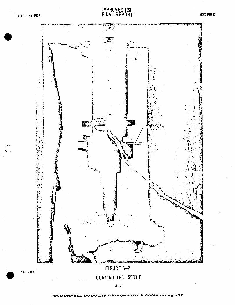
4 AUGUST 1972IMPROVED RSIFINAL REPORT MDC E0647
C
437-2559FIGURE 5-2
COATING TEST SETUP
5-3
MCDONNELL DOUGLAS ASTRONAUTICS COMPANY - EAST

IMPROVED RSI4 AUGUST 1972 FINAL REPORT MDCEOS47
Test Results - Results of flexure tests are presented in Figure 5-3. All
specimens were tested in the "as fabricated" condition and all specimens were loaded
to failure. Specimen geometry, ultimate strength, and elastic modulus are listed
for each specimen tested.
The tensile strength and modulus of elasticity of the coating were computed
from the test data using linear-elastic beam theory. Thickness of coating on each
specimen was measured. It was not possible to tell during the test if the first
surface to fail was in tension or compression. However, previous tests of coated
tension and compression specimens, reported in Reference (b), indicated the compres-
sive strength to be much larger than the tensile strength. Coating strengths were,
therefore, assumed to be tensile.
The coating elastic modulus was assumed to be the same in tension and compres-
sion and much greater than the HCF modulus. The coating modulus was determined fromt,
the flexure specimen load deflection curve. Calculations indicated that HCF shear
deflections were a significant part of total specimen deflections. Deflections due
to shear were therefore calculated and subtracted from measured deflections to deter-
mine modulus,
Coating tensile strength and elastic modulus are plotted in Figures 5-4 and
5-5. Also shown are results of tests conducted during the Reference (b) program. A
computer program entitled "General Least Squares Analysis" was used to fit the curves
5.2 THERMAL PROPERTIES - Various coatings in different phases of development
were exposed to the expected shuttle thermal environment, then surface character-
istics such as smoothness, etc., were evaluated. Selected coatings were applied
to full sized tiles and were then further tested. Other necessary properties such
as emittence of high temperature, and thermal expansion characteristics were also
determined; these are discussed in this section along with the thermal exposure
results.
5-4
AfCDO/V/VELL DOUGLAS ASTRONAUTICS COMPANY' EAST "'•

4 AUGUST 1972IMPROVED RSIFINAL REPORT MDC E0647
L
TESTTEMPERATURE
<°F)
ROOMTEMPERATURE
_.
900
1200
1500
SPECIMENNO.
1221161092
AVERAGE
18
15
AVERAGE
35
22
AVERAGE
46
25
AVERAGE
*t(IN.)
0.1320.1240.1330.1340.1290.127
_
0.1230.1420.135
-
0.1290.1360.130
-
0.1340.1360.131
-
»1(IN.)
0.0140.0120.0120.0090.0100.010
-
0.0100.0100.012
-
0.0150.0100.012
-
0.0130.0140.010
-
'2(IN.)
0.0120.0150.0140.0130.0110.010
_
0.0100.0120.013
-
0.0120.0120.013
-
0.0140.0120.010
-
b(IN.)
0.3670.3640.3660.3720.3650.367
—
0.3580.3710.368
-
0.3690.3680.369
-
0.3670.3700.367
-
ULTIMATESTRENGTH
LB/IN2
2378227619392080 .18152290
2130
620219541807
3321
283642683076
3393
121416271943
1595
ELASTICMODULUS
LB/IN2
13.1 x 10⁶
6.6 x 10⁵
8:2 x 10⁶
6.6 x 10⁶
28.5 x 10⁶
10.4 x 10s
12.2 x 10⁶
13.5 x 10⁶
10.1 x 10⁶
9.5 x 10⁶
11.0 x 10⁶
«
6.6 x 10⁶
8.0 x 10⁶
7.3 x 10⁶
1.0 x 10s
1.7 x 10⁶
2.5 x 10⁶
1.7 x 10⁶
FIGURE 5-3
COATING MECHANICAL PROPERTY TEST RESULTS
line least squares curves to the test results. The large scatter in test results
is typical, of brittle ceramics.
Low-Pressure, High-Temperature Testing - This work was conducted in two
phases: the developmental phase in which new coatings were applied to 2 by 2 by
2-inch HCF test specimens, and the scale-up phase in which the new coatings showing
the improvements were applied to 6 by 6 by 3-inch or 3.5-inch thick HCF tiles. The
specimens were tested in the graphite heater facility at 2300°F and at 2500°F max-
imum temperature and at 10-tcrr air pressure. The.; test chamber and graphite heater
assembly are shown in Figure 5-6. The time/temperature profiles used for these
tests are shown in Figure 5-7.
MCDONNELL DOUGLAS ASTKONAUTICS COMPANY • EAST

4 AUGUST 1972
7000
6000
• 5000
1i
£ 4000LLJce
3000
2000
1000
0-500
D
D
IMPROVED RSIFINAL REPORT MDC E0647
O MDAC-WEST TESTS
D PREVIOUS TESTS(REFERENCE B)
500 1000
TESTTEMPERATURE~OF,
FIGURE 5-4COATING TENSILE STRENGTH
5-6
MCDONNELL. DOUGLAS ASTRONAUTICS COMPANY » EAST

4 AUGUST 1972
IMPROVED RSIFINAL REPORT MDC E0647
Xtst
O
o
0£
'ft
24
20
16
12
P
4
D
a.^^^
D
O
e,n4J
O ^^
B ^oaeD
O
0O
^v^^^^s
O MDAC-WEST TESTS
D PREVIOUS TESTS(REFEREN(
O,
S^°
^s
<
;EB>
fc.
?\-500 0 500 1000 1500 2000
457-2546
TEST TEMPERATURE °F
FIGURE 5-5 '
COATING ELASTIC MODULUS
5-7
DOUGLAS ASTftOIVAUTICS CO/Vf*»/»/VV - EAST

4 AUGUST 1972IMPROVED RSIFINAL REPORT MDC E0647
TEST SPECIMEN LSUPPORT PANEL '
457-2575
FIGURE 5-6
ENVIRONMENTAL TEST CHAMBER AND SUPPORT FIXTURE
The developmental and full-scale test specimens were bonded to a water-cooled
copper plate which holds the specimens in position above a columbium susceptor
panel. The susceptor panel is, in turn, heated by the graphite resistance heating
elements which are kept in a vacuum. The time/temperature profile was controlled
according to Space Shuttle requirements.
A test panel shown in Figure 5-8, containing the 2 by 2-inch development test
specimens, was used to determine the high-temperature, low pressure stability of
the new one-step coatings compared with our standard MMpP 7 coating. The basic
function of the test was to determine what constitutents, either pigment or glass,
5-8
DOUGLAS ASTRONAUTICS CO/V»FV»/VV - EAST

c
4 AUGUST 1972
28001—
2400
2000
1600
IMPROVED RSIFINAL REPORT MDC E0547
2500°F MAXIMUM TEMPERATUREHEAT PULSE
2300°F MAXIMUM TEMPERATUREHEAT PULSE
1200
1200 1600 2000 2400 2800 3200
57-2434 TIME (SECONDS)
FIGURES-?
TEMPERATURE - TIME PROFILES FORSHUTTLE ENTRY SIMULATION
would be volatile and would cause blistering at 2500°F, 10-torr air conditions.
The following one-step coatings were tested: SiC, MoSi™, ZrB-, WSi_, and B^Si
pigments in conjunction with borosilicate and alurcinosilicate glasses. Silica
(SiO_) was added to the one-step coatings to reduce blistering at low pressure and
high temperatures. Testing on the MMpP 7 and Mo7 coatings at low pressure and
high temperature had resulted in blistering of the coatings at 2500°F. Also, the
5-9
MCDOIV/VELL DOUGLAS ASTRONAUTICS COIHIPAIW • EAST

4 AUGUST 1972
IMPROVED RSIFINAL REPORT MDC E0647
457-2S72FIGURE 5-8
DEVELOPMENTAL COATING SPECIMENS FOR LOW PRESSURE TESTING
ability of the coatings to remain liquid waterproof during the test was a major
test criterion in selection of an improved coating. The developmental specimens
were then heated on a total of six cycles to peak temperatures of 2300°, 2400°,
and 2500°F under 10-torr air pressure conditions. The coatings were inspected
after each cycle for oxidation, cracking, blistering, and retention of liquid water-
proofing. The coating formulations showing the most promise were as follows:
PIGMENT GLASS OTHER
Borosilicate
Borosilicate
5-10
a. B4Si
b. B-Sio
DOUGLAS ASTRONAUTICS COMF>A*IY • EAST

IMPROVED RS!4 AUGUST 1972 FINAL REPORT MDCE0647
» B.Si Borosilicate Si00 (reduce blisters)c. . 4 2
d. SiC (fired @ 2300°F) Aluminosilicate
e. SiC (fired @ 2500°F) Aluminosilicate
f. SiC (fired @. 2300°F) Aluminosilicate PbO (flux)
g. WSi2 Borosilicate
The earlier MoSi_/borosilicate glass mixtures and the MMpP 7 baseline
coating both blistered after 2500°F exposure at 10 torr, although the latter
did not blister severely and remained waterproof. The SiC/Aluminosilicate
glass coatings were fired at 2500°F to achieve liquid waterproof coatings
because firing at 2300°F did not result in a waterproof coating. The addition
of flux, lead oxide (PbO) to this coating provided a waterproof coating after
firing at 2300°F. During testing at 2500°F (low pressure), the SiC17 coatings
which were fired at 2300°F became liquid waterproof. These coatings thereafter
remained smooth and waterproof during test. The B.Si and B,Si/glass mixtures
exhibited some discoloration, but did not blister or lose liquid waterproofing
during testing. The WSi2/glass coating performed in a similar manner.
After the low-pressure testing, the specimens with the most promising coatings
were subjected to oxyacetylene torch testing in air at 2300° and 2500°F
for 5-minute cycles to determine the effect of high-temperature exposure at
one atmosphere on the coatings. The B,Si/glass coatings remained waterproof
throughout the testing. The SiC/glass coatings which had been fired at 2300°F
lost their liquid waterproofing ability and began to bloat. The SiC/glass
coatings which had been fired at 2500°F did not bloat, but the coating
delaminated from the HQF. Overall, the best coating composition was the
B,3i/Si02/7740 mixture, designated B-7, which exhibited little change through
the torch testing. The WSi2/glass coating oxidized extensively and was
eliminated. The B-7 coating and modifications of the MoSi2/glass and SiC/
- - • — 5-11 '
MCDONNELL DOUGLAS ASTRONAUTICS COMPANY* E AST

IMPROVED RSI4 AUGUST 1972 FINAL REPORT MDCEOS47
glass coatings (to reduce blistering and bloating) will be scaled up as a s
future developmental activity.
Emittance Measurement - The total normal spectral emittance of coated and
uncoated Mod IIIA mullite HCF was measured using a push-pull apparatus (shown in
Figure 5-90 heated by an Astro tube furnace.
The total normal emittance of coated HCF was measured by a method that is
based upon the comparison of the energy emitted by the test specimen and a black-
body cavity at the same temperature. The specimen is mounted at the rear of a
heated cavity on the end of a pushrod. In this position, the specimen can be
moved to any location within the cavity up to the aperture. The emitted energy
is detected by a fast response thermopile. The energy received when the thermo-
pile "sees" the black-body cavity (specimen at initial position) is considered as
1.0.and as zero when the field of view is closed (specimen at final position). The
specimen is moved rapidly to the aperture and is "seen" by the thermopile. This
action corresponds to the time interval AT and is typically 0.2 second. Specimen
cooling then begins as it radiates to the water-cooled sight port. It is important
to account for specimen cooling effects since the ratio of emitted energy from
the specimen in the two locations is used as the basis for the emittance deter-
mination (Figure 5-10). This cooling effect can be estimated by extrapolating
the cooling curve through the AT time span. Except for specimens where cooling
is very rapid, the error introduced in emittance determinations is typically
+0.02 emittance units.
The Model 2570C Astro furnace is resistance heated using a graphite tube as
the heating element. Two components make up the pushrod mechanism: a stainless
steel rod with a water cooling tube through the center, and a coated graphite rod.
One end of the graphite rod is machined to form a sample holder. A stainless steel
;. . . . *kstud is used to connect the two parts of the pushrod mechanism, and sealing rings are Jr
5-12
MCDOIVIVEt-L DOUGLAS ASTRONAUTICS COMfAWY - EAST -•

4 AUGUST 1972IMPROVED RSIFINAL REPORT MDC E0647
C
SAMPLE(INITIAL POSITION)
THERMOPILESHIELD
SIGHT -|~WINDOW C
TO /AMPLIFIERSRECORDER
457-2S24
- FURNACE
WATER OUT
JLJ (J WATER IN
SAMPLE{FINAL POSITION)
ZIRCONIUM OXIDE TUBETHERMOPILE
FIGURE 5-9
TOTAL NORMAL EMITTANCE ACCESSORY
lO'
£ 827°= 6UJ c_j 5
IS01 rLU 2
= 0.90
BLACK BODY -, —
ENERGY SPECIMEN \LEVEL EMITTANCE
ENERGYLEVEL
t
SPECIMENCOOLING CURVE
TIME
FIGURE 5-10
THERMOPILE RESPONSE CURVE FOR e= 0.65 AND e= 0.9
5-13
MCOONKIEt-L DOUGLAS ASTRONAUTICS COMfAfilY - £ AST

IMPROVED RSI4 AUGUST 1972 FINAL REPORT MDCE0647
provided around the pushrod and under the cover plate to enable furnace depressur-
ization.
The emittance of all the new coatings was not measured, however, the eraittance
as a function of temperature of the SiC17, MiSi_ and MMpP 7 coatings can be closely
estimated from test data on the M25A7 coating, Figure 5-11 and from data on the
overcoatings for the M5A7 coating containing the emittance of pigments (MoSi^, SiC,
Co-Fe-Cr oxide mixture).
The emittances of these surface overcoatings as a function of test temperature
are shown in Figure 5-12 and is compared with uncoated HCF material. The emittance
of boron silicide pigments was not measured, but the emittance of this material is
estimated to be in excess of 0.8.
Note that the SiC and MoSi pigments have greater emittance values at lower
temperature Chan the standard M25A7. The M25A7 emittance should be equivalent to
that of the MMpP 7 system because both utilize a chromic oxide pigment. The inor-
ganic bonded P-700 pigment (Co-Cr-Fe oxide) used as an overcoating increases the
emittance from 0.78 to 0.82 when applied to the M25A7 or MMpP 7.
Although the nonoxide pigments possess high emittance at lower temperature,
elevated temperatures result in a marked decrease in emittance due to oxidation.
The current one-step coatings are mixtures of glass and nonoxide pigments; the glass
provides oxidation protection for the pigment and the high emittance is maintained
at higher temperatures. As an example, the SiC pigmented coating without glass
protection shows a degradation of emittance, but the SiC/17 glass mixture retains
its original emittance and is an improvement over the standard coating. From these
data, the predicted emittance data for the temperature range of 2000° to 2500°F for
the new coatings are given in Figure 5-13.
Coating Thermal Expansion Measurement - The linear thermal expansion as a
function of temperature of the various coatings and the Mod IIIA mullite HCF from
5-14 " .
MCOOIV/VELL DOUGLAS ASTRONAUTICS CO/VfRa/VK - EAST
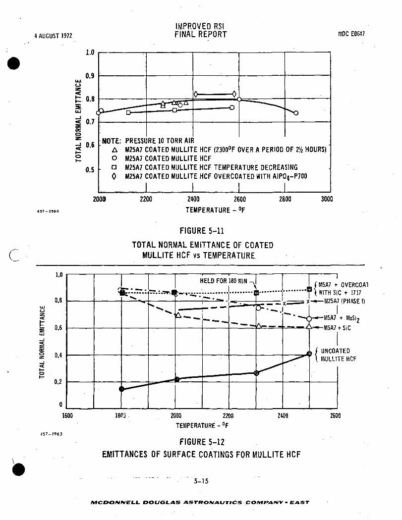
4 AUGUST 1972IMPROVED RS!FINAL REPORT MDC E0547
LU0
1.0
0.9
0.8
UJ
a »•'oeo
«to
0.6
0.5
NOTE: PRESSURE 10 TORR AIRA M25A7 COATED MULLITE HCF (2300°F OVER A PERIOD OF 254 HOURS)O M25A7 COATED MULLITE HCFD M25A7 COATED MULLITE HCF TEMPERATURE DECREASING0 M25A7 COATED MULLITE HCF OVERCOATED WITH AIP04-P700
2000 2200 2400 2600
TEMPERATURE - °F
2800 3000
C
FIGURE 5-11
TOTAL NORMAL EMITTANCE OF COATEDMULLITE HCF vs TEMPERATURE
1600
457-1963
IM5A7 + OVERCOATWITH SiC '+ 1717
x-*—M25A7 (PHASE I)
-*-u I I""" ' —<W-M5A7 + MoSi2
UNCOATEDMULLITE HCF
1803 2000 2200
TEMPERATURE - °F
2600
FIGURE 5-12
EMITTANCES OF SURFACE COATINGS FOR MULLITE HCF
5-15
MCDONMEl-L. DOUGLAS AST-ROMAUTHCS COMPANY ' EAST

IMPROVED RSI4 AUGUST 1972 FINAL REPORT MDCEOE47
COATING • (TOTAL NORMAL EMITTANCE) '
2000°F 2500°F
M25A7 0.73 0.80
MMpPcr7* . 0.73 0.80mpPcr7P700 (OVERCOATED)* 0.82 0.82
Mo7 (MOLYBDENUM DISILICIDE PIGMENT)* 0.88 0.84
S1C17 (SILICON CARBIDE PIGMENT)* 0.88 0.88
B7 (BORON SILICIDE PIGMENT)* GREATER THAN 0.80
'PREDICTED FROM FIGURES 3-26 AND 3-27
437-2565 FIGURE 5-13
ACTUAL AND PREDICTED EMITTANCES FOR HCF COATINGS
room temperature to 2500°F and back to room temperature was measured using a modi-
fied Astro tube furace. This apparatus can provide expansion measurements from
500°F to 5000°F. The expansion of 3 by 0.25 by 0.25-inch test specimens was measured
optically using a calibrated telescope to observe the change in distance between
two slots which were machined in the bars; the expansion was determined by dividing
the expansion or contraction by the distance between the slots.
The thermal expansion of a coating should closely match the expansion of the
HCF material to reduce stresses between the coating and the HCF. A comparison of
the thermal expansion coefficients of the various coatings developed is presented
in Figure 5-14. Note that the Mod IIIA material exhibited very little dimensional
change after the 2500°F test exposure. The thermal expansion of the Mod IIIA in
both orthogonal directions of fiber orientation is plotted in Figure 5-15. The
expansion in the X-Y plane of the HCF material could possibly be attributed to
grain growth in the mullite fibers. The thermal expansion of the mullite fiber
based M5 base coating was developed to match closely'that of the HCF and is plotted
as a function of temperature in Figure 5-16. A large permanent expansion which
occurred in this coating at 2200°F was decreased by altering the binder used in the
base coating.
5-16
DOUGLAS ASTRONAUTICS CO/VTPVt/V V - EAST
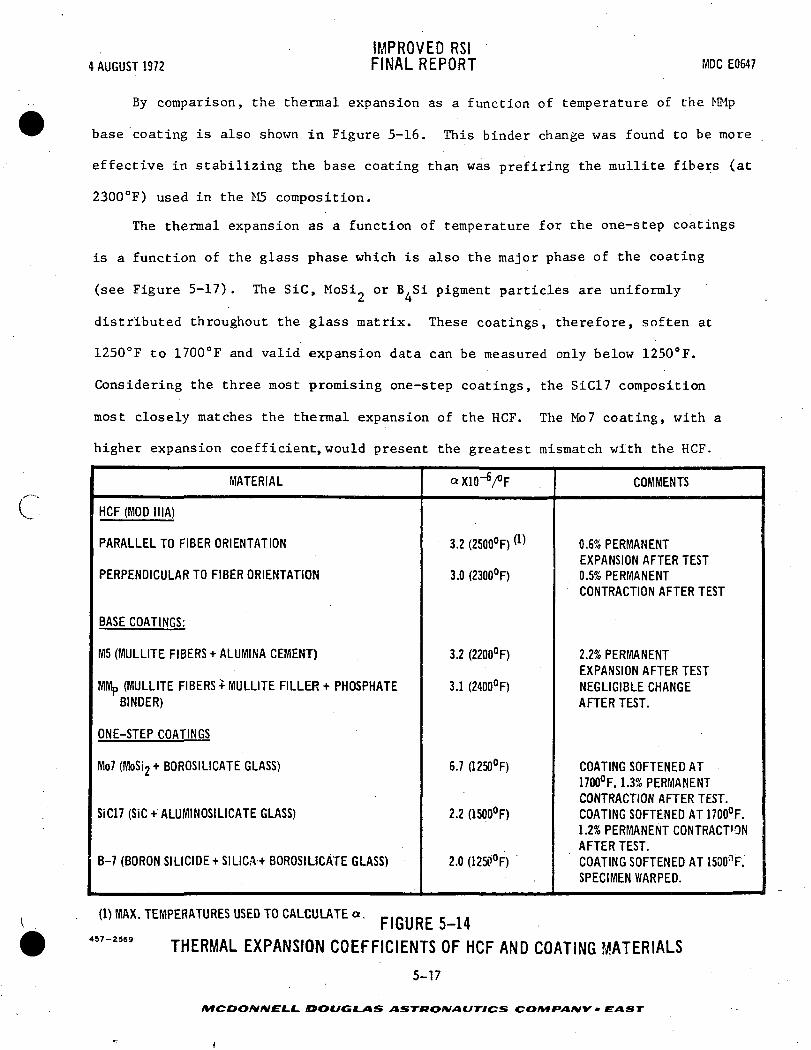
4 AUGUST 1972IMPROVED RSIFINAL REPORT MDC E0647
c
By comparison, the thermal expansion as a function of temperature of the MMp
base coating is also shown in Figure 5-16. This binder change was found to be more
effective in stabilizing the base coating than was prefiring the mullite fibers (at
2300°F) used in the M5 composition.
The thermal expansion as a function of temperature for the one-step coatings
is a function of the glass phase which is also the major phase of the coating
(see Figure 5-17) . The SiC, MoSi^ or B.Si pigment particles are uniformly
distributed throughout the glass matrix. These coatings, therefore, soften at
1250°F to 1700°F and valid expansion data can be measured only below 1250°F.
Considering the three most promising one-step coatings, the SiC17 composition
most closely matches the thermal expansion of the HCF. The Mo7 coating, with a
higher expansion coefficient, would present the greatest mismatch with the HCF.
MATERIAL
HCF (MOD IIIA)
PARALLEL TO FIBER ORIENTATION
PERPENDICULAR TO FIBER ORIENTATION
BASE COATINGS:
M5 (MULLITE FIBERS + ALUMINA CEMENT)
(MULLITE FIBERS + MULLITE FILLER + PHOSPHATEBINDER)
ONE-STEP COATINGS
Mo7 (MoSi2+ BOROSILICATE GLASS)
SiC17 (SiC +ALUMINOSILICATE GLASS)
B-7 (BORON SILICIDE +SILICA + BOROSILICATE GLASS)
aXlO'V'F
3.2 (2500°F)
3.0 (2300°F)
3.2 (2200°F)
3.1 (2400°F)
6.7 (1250°F)
2.2 (1500°F)
2.0 (12»°F)
COMMENTS
0.6% PERMANENTEXPANSION AFTER TEST0.5% PERMANENTCONTRACTION AFTER TEST
2.2% PERMANENTEXPANSION AFTER TESTNEGLIGIBLE CHANGEAFTER TEST.
COATING SOFTENED AT1700°F. 1.3% PERMANENTCONTRACTION AFTER TEST.COATING SOFTENED AT 1700°F.1.2% PERMANENT CONTRACT'ONAFTER TEST.COATING SOFTENED AT 1500nF.SPECIMEN WARPED.
(1) MAX. TEMPERATURES USED TO CALCULATE a.
457-3569
FIGURE 5-14THERMAL EXPANSION COEFFICIENTS OF HCF AND COATING MATERIALS
5-17
MCDOMNEL-L. DOUGLAS >»STWO/V/»C/T7CS CO/Vf fVl/VV - EXIST

.4 AUGUST 1972IMPROVED RSIFINAL REPORT MDC E0647
16
12
S 4x
LEGEND:
A PARALLEL TO X-Y PLANE(PLANE OF PREFERRED
. ORIENTATION OF FIBERS)
O NORMAL TO X-Y PLANE
EXPANSION COEFFICIENTS:
a = 3.2 X 10~6 IN./IN./°F
a = 3.0 X 1<T6 IN./IN./°F
/
A,/
457-2528
0 ' 500 1000 1500 2000 2500
TEST TEMPERATURES - °F
FIGURE 5-15
AL/L OF MOD MIA AS A FUNCTION OF TEMPERATURE AND SPECIMEN ORIENTATION
5-18
i.I_ DOUGLAS ASTRONAUTICS COMfANY - EAST

4 AUGUST 1972IMPROVED RSIFINAL REPORT MDC E0647
32
C
28
24
20
x 16
12
LEGEND: |O MS BASE COATING
A Mp BASE COATINGi
EXPANSION COEFFICIENTS:
a = 3.2 X 10"6 IN./IN./°FO
a = 3.1 X 10"6 IN./IN./°F
500 25001000 1500
TEST TEMPERATURE - °F ''"
FIGURE 5-16COMPARISON OF THERMAL EXPANSION OF M5 BASE COAT WITH MMp BASE COAT
457-2370
5-19
MCD ~>/V/VELL DOUGLAS ASTKOKJAUTICS COMfAHY'' EAST
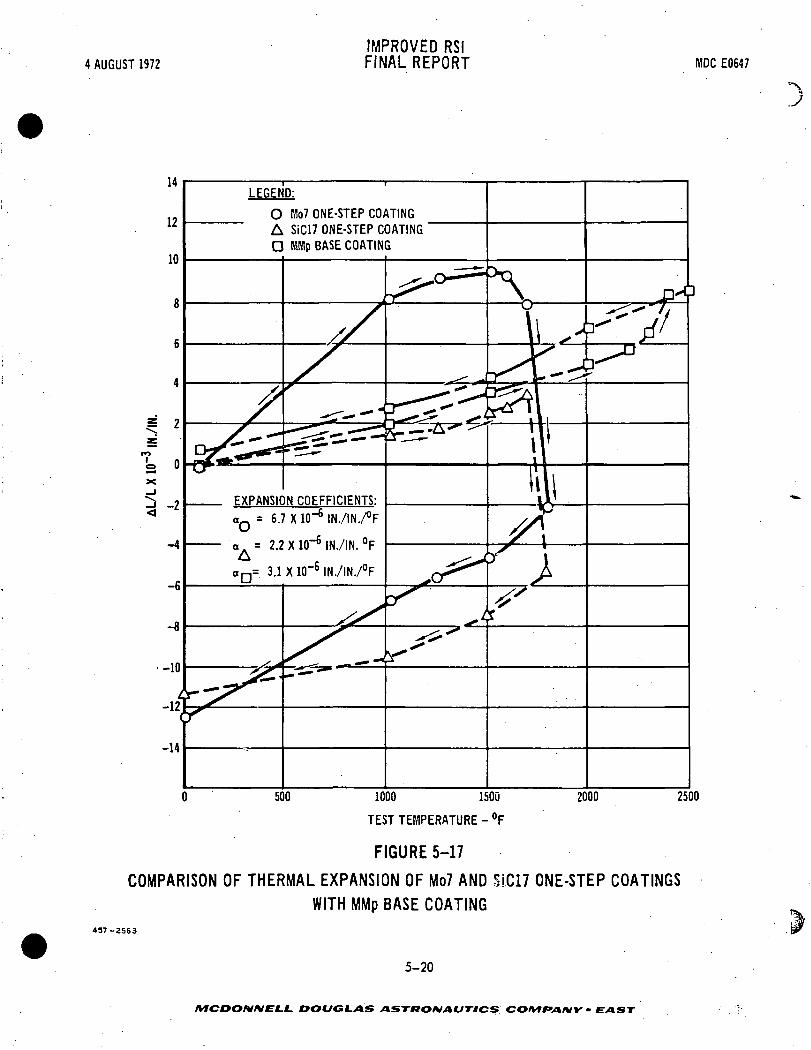
4 AUGUST 1972
12
10
8
6
5 2
-4
-6
IMPROVED RSIFINAL REPORT MDC E0647
LEGEND:
O Mo7 ONE-STEP COATINGA SiC17 ONE-STEP COATINGD WMp BASE COATING
EXPANSION COEFFICIENTS:aQ = 6.7 X ID"6 IN./IN./°F
a. = 2.2 X 10"6 IN./IN. °FA
500 1000 1500
TEST TEMPERATURE - °F
2000
FIGURE 5-17
COMPARISON OF THERMAL EXPANSION OF Mo7 AND SIC17 ONE-STEP COATINGSWITH MMp BASE COATING
457-2563
5-20
MCDOMIVELL DOUGLAS ASTRONAUTICS COtVlfAKUV" EAST

IMPROVED RSI4 AUGUST 1972 FINAL REPORT NIDCE0647
6.0 REINFORCEMENT
The objective of reinforcing HCF is to hold the material together in case of
cracking. The approach taken was to emplace a reliable, continuous, high strength
filament. Although reinforcement may also increase the ultimate strength of the
HCF material, this was not the goal of our effort.
6.1 MATERIALS CONSIDERED - Astroquartz* (Si02> and Zircar** (ZrO threads,
which have breaking strengths of approximately 20 pounds and 4 pounds, respectively,
were considered for reinforcement materials because of their oxidation resistance,
temperature resistance, and availability in thread form. Small test samples of
these threads in HCF were fabricated and heat treated to 2150°F. Both the SiO 'and
ZrO_ threads became brittle and lost all appreciable strength when fired to 2150°F.
Columbium, platinum, nickel-chromium, and Kovar wires were then considered as
_ HCF reinforcements; however, only Cb and nichrome specimens were fabricated.
~- 6.2 CERAMIC THREAD REINFORCEMENT - Figure 6-1 shows the fixture used to hold
the silica thread in place during the felting operation. The threads were strung
with 3/4-inch spacings in three orthogonal directions. Using conventional felting
techniques, the HCF slurry was poured through the fixture. The felt formed around
the reinforcement threads into a continuous block without voids. The block of
material was cured before removing the sides and top of the mold. The block was
then fired at 2150°F in 16 hours. Figure 6-2 shows the HCF block reinforced with
the threads before machining.
The material used to construct the supporting frame tooling was commercial
acrylic sheet, The box frame was constructed of 1/4-inch thick acrylic sheets,
3 inches wide and 1-1/2 inches long, to form the four sides of the frame. One-
eighth-inch holes were drilled on three-quarter-inch centerlines laterally and
longitudinally, to allow insertion of the thread in two axes. Positioning in the( ' * J. P. Stevens Co.
** Union Carbide
. . . . - -'.. 6-1
MCDONNELL DOUGLAS ASTRONAUTICS COMPANY • £AST
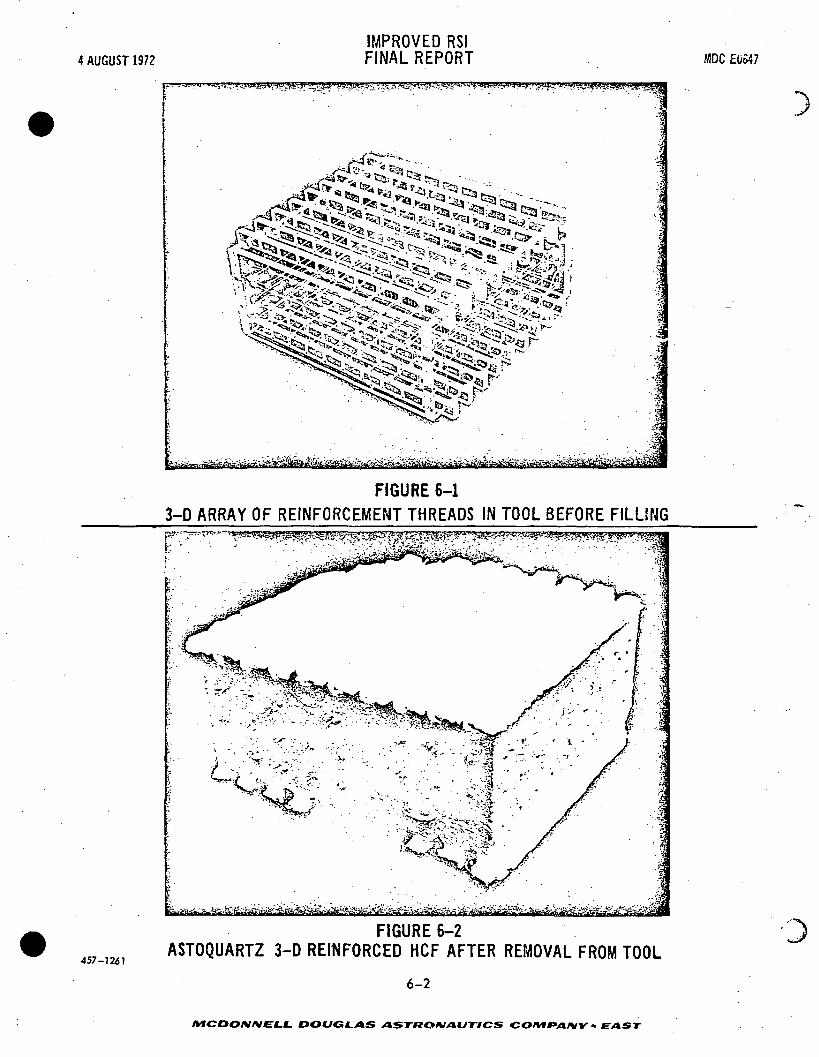
4 AUGUST 1972IMPROVED RSIFINAL REPORT MDC EU547
457-1261
^ -i- ^c^^"^^^ I. v^
ftfe»3t«v<a!^ii&^&B£B^iy
IMPROVED RSI4 AUGUST 1972 FINAL REPORT - MDCE0647
assembly of the four sides was accomplished by 3/16-inch diameter acrylic dowels.
Fiber tension provided mechanical fastening of the mold. A series of 1/2-inch wide,
1/4-inch thick acrylic bars with 1/8-inch holes in 3/4-inch centers drilled through
the 1/2-inch width provided a grid support for the fibers in the Z axis.
The box frame was assembled and Dacron polyester thread was used in a trial
fabrication. The fiber insertion or "string up" method used was an 8-inch long
needle passed back and forth through the holes provided. The fibers were first
pulled through the two sides parallel to the locator dowels (to be referred to as
the X axis) to provide mechanical assembly of the four frame (or box) sides. Next,
the fiber was strung through the two sides perpendicular to the X axis. The 1/4 by
1/2-inch acrylic bars were progressively added as thread was inserted in the Z axis,
resulting in a cubic lattice. Notches were provided in the box sides of the X axis
^_ to locate the Z axis support bars. The assembly method described above was chosen
""' because it provided simple disassembly of the completed specimen by cutting exterior
loops without potential damage to the completed HCF composite. The actual Astro-
quartz thread (#300-4/4) specimen was fabricated as outlined above.
Preliminary cost estimates indicated that an additional 20 manhours would be
required to produce one cubic foot of silica thread reinforced HCF compared to
unreinforced material. This included only the time required for threading the
reinforcement through the tool on 3/4-inch centers. Tooling, planning, and other
related costs were not included.
6.3 NICHROME WIRE REINFORCEMENTS - The first wire reinforcement concept
evaluated used reinforcement only across the thickness. It was felt that this
reinforcement would provide support if delaminations should occur in the weaker
HCF plane (parallel to the moldline).
Initial specimens were fabricated using nichrome wire inserted in predrilled
holes in fired HCF. It was found that pulling the wires into position with a small
6-3
DOUGLAS ASTflOMAVnCS CO/V»*V»/VV • EAST

IMPROVED RSI4 AUGUST 1972 FINAL REPORT MDCEOB47
force could easily cut through HCF. It was thought that vibration might cause this
catting in service. An alternate method was devised to hold the reinforcement
wires using 99-percent alumina tubes. These tubes provide a wire path during
insertion and also a bearing surface to prevent cutting (Figure 6-3). The ceramic
bearing concept was dropped because coating application was difficult and the alumina
tubes tended to work loose during thermal cycling.
Using a 3-D orthogonal array of 0.010-inch diameter nichrorae wires, two felts
were fabricated, one using the RSB-2 binder system and a second using precursor
silicone binder. In both cases it was found that the wires could be easily pulled
out of the. part. It was thought that if these wires were to provide reliable
retention of large, cracked pieces of HCF, the wires should be welded at their
intersections to prevent possible pullout. Radiographs were taken in two directions
of 3-D wire reinforced HCF to detect any possible voids which might be present due
to the wire reinforcements. No voids were detected, as shown in Figure 6-4. It
was concluded that sound HCF felts can be fabricated with 3-D wire reinforcements
using our present felting processes.
3-D Welded Nichrcme Wire Reinforcement Concep_t - One 3-D reinforced HCF
specimen was fabricated using 0.030-inch diameter nichrome wire. The nichrome
trusswork was 7 by 7 by 1/2-inch and the wires were spaced on 3/4-inch centers.
3Each intersection of wires was welded. Figure 6-5 shows the 14.2 Ib/ft tile,
including the weight of the support pads. The silicone precursor technique was
used to form this reinforced HCF block. The part was cured at 150°F for 2 hours
and then fired for 2 hours at 1500°F. The part was trimmed to final dimension
and coated with a high emittance ceramic. Figure 6-6 shows that no voids in the
HCF are detectable by X-ray.
- - - - - - - - - - 6 - 4
/WCOO/V/VEf-L DOUGLAS ASTRONAUTICS COMPANY • EAST

4 AUGUST 1972IMPROVED RSIFINAL REPORT MDC EOG47
c
EiKii
FIGURE 6-3
ONE DIMENSION WIRE REINFORCED HCF WITH ALUMINA TUBE BEARING SURFACES
457-1767
6-5
/VfCDO/V/V£-f-f- DOUGLAS ASTtTOMAUTlCS COMfANY - EAST

4 AUGUST 1972IMPROVED RSIFINAL REPORT MDC E0647
liv,^.0
•
v'
~- — :.V>vr:: — - : . " . - -
• . ' ••. •( :-* / i
. i . ,
i - ! •
'. * ' i
••- .. .v';:';.v/— . f : ..:/. - • - V -, • • *' - - •• f f' - 11 —
' . ' } • • ' . • . • - • . • • ! - . - / •i .i ' •
.;/ •• .:.4..__.;_ .> ' •. ,: . ^
. . . ' ' : ' • / • _' . ' ;
v" _* - - J~* - - • • • - = » • - - . - - - - x r - "X . *i • • • •" -
","^_ - , 1. .-.t "~ -1" ' •' '. -".-: .4>'.-> „ •
. »! .. ' » — . --.. - - - -.1
• - ' ' - : . ' - ' ' ' .
.
X j
. • •*"
*" v^ •' '"
V ' ,\
' :"'-r*T "r
; . -;!'.. -4''i '*-
, . '.•.'ffT"
-:--^vi3?f|
: ';::;Sfe' •••'•i^-
• --f-- t-:.
:---- • :->r ;A^M4^oSlfe'
PLAN VIEW EDGE VIEW
457-1772FIGURE 6-4
TWO VIEW X-RAYS OF 3-D WIRE REINFORCED HCF SHOWING VOID-FREE TEXTURE
6.4 COLUMBIUM WIRE REINFORCEMENT - Three columbium wire arrays were fabri-
cated to reinforce HCF. Coated columbium was selected as the best candidate wire
material because it most closely matches the thermal expansion of HCF and is
usable to 2500°F.
Partial Depth Columbium Wire Array - A layer c.f packaged insulation
(Hastelloy X metal foil and Microquartz insulation)'was included in the partial
depth columbium wire grid design. Figure 6-7 shows the columbium wire reinforce-
ment, the insulation package, and the substructure. The attachment points of the
6-6
AfCr-O/V/VELf. DOUGLAS ASTRONAUTICS COMfAtVY • EAST
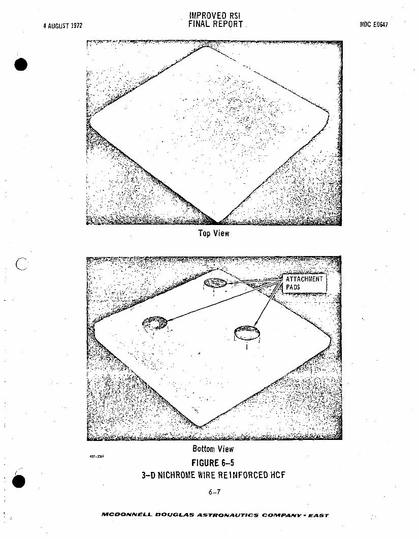
4 AUGUST 1972
IMPROVED RSIFINAL REPORT MDC E0547
FT
c
: ' •>•.#••;<••:..••••:-•.•" • ' ^v^";.':•:*-*
£r-:£' , •• v\>: «
••' ' ;Svv^• . ••,•-•?}.<?*.]L. .' • ii-i.c
;%S/?,A?;^s>!..
Top View
- " - , ' * • . , \ • ~'\c">" * ,. • '•;:', Vr'"Vn3
"•:»-.• .•••^4^":e^^^i
-.iilBIll
.?.; ~tl lj ^ ^
Bottom View
FIGURE 6-53-D NICHROME WIRE REINFORCED HCF
6-7
/MCOOrWEC.1. DOUGLAS ASTRONAUTICS COMPANY - EAST

4 AUGUST 1972IMPROVED RSIFINAL REPORT MDC F.0647
HCF
• ; . . . - :••;. .,:;:::;:..:-.-;'-..-.7$0.030 IN.1 DIAMETER NICHROIYIE WIRE
FIGURE'6-6X-RAY OF NICHROME WIRE REINFORCED HCF
Improved RSI
columbium reinforcement extended through the packaged insulation and were mechan-
ically attached to the primary structure. In order to prevent high temperature
oxidation of the columbium alloy (Cb-752) wire structure, a coating was applied
A fused slurry silicide coating (60 Si-20Cr-20Fe) was applied by dipping; it
was fired in an argon atmosphere in a graphite furnace at 2600°F for one hour.
The coating obtained was the desired thickness 3 +f;.-5 mils per side, but the
columbium base metal remaining was so embrittled that the wire structure could
not be handled without breaking some wires. Two broken pieces of wire, one 15
._ 6-8
MCDOIVIVELI- DOUGLAS ASTRONAUTICS CO/VfPA/VV - EAST

4 AUGUST 1972IMPROVED RSIFINAL REPORT MDC E0647
• "-x
cPrimary Structure Packaged Insulation
Cb Wire Grid FIGURE 6-7 Total System
3D COLUMBIUM WIRE REINFORCEMENT FOR HCF
6-9
MCDONNELL DOUGLAS ASTRONAUTICS COMPANY • EAST

IMPROVED RS!4 AUGUST 1972 . . FINAL REPORT MDCE0647
mils in diameter and the other 40 mils in diameter, were submitted for metallo-
graphic cross-sectioning in an attempt to determine the cause for embrittlement.
Photomicrographs are shown in Figures 6-8 and 6-9. There are many indications
of carbides which are much more predominant than would be expected in wire
products as supplied by the manufacturer. Oxides and nitrides are not as
easily identified as carbides by visual observation, but are suspected of being
major contributors to the embrittlement which was experienced due to poor
atmospheric control during diffusion coating.
Full Depth Columbium Wire Array - An oxidation protective coating was applied
to this array by Sylvania. The array had a full depth (thickness) HCF compared
with the first columbium array which had a half-thickness reinforced HCF. In the
first array, a space was provided below the array for efficient thermal insulation.
A one-inch spacing was used in making the second array using 0.032-inch
diameter columbium wire. The bracing and legs were made from 0.04-inch diameter
columbium wire. The legs were welded to columbium pads which were 0.063 by 1.375
inches in diameter. Each pad contained a 0.312-inch diameter hold which was pro-
vided for mechanical attachment to the airframe structure.
All intersections of wires were welded. Welding of this second array was
more simply done because the larger diameter wires were used. The wires in the
first array were 0.015-inch in diameter. The oxidation protective coating was
applied by the fused slurry silicide process and was composed of 60 percent Si,
20 percent Cr, and 20 percent Fe. No embrittlement problems, such as had occurred
on the first array were observed.
The array was visually inspected and appeared to be free of excess coating;
it was quite smooth and uniform in color. All welds were tight before and after
coating. The array was filled with mullite HCF and then dried and fired in the
normal manner for HCF. The results of filling the array were excellent. See
- "6-10 '
MCDONNELL DOUGLAS ASTRONAUTICS COMPANY * EAST

4 AUGUST 1972
c
497-2439.
IMPROVED RSIFINAL REPORT
100X
• • - • - - . ^.t&smim• - - ... fe, '$&&$%£&
D&^ - ^^AS
FIGURE 6-8CROSS SECTION OF 15 MIL DIAMETER,
EMBRITTLED, COATED COLUMBIUW-WIRE
MDCE0647
6-11
MCDONNELL DOUGLAS ASTRONAUTICS COMe*ANY - EAST
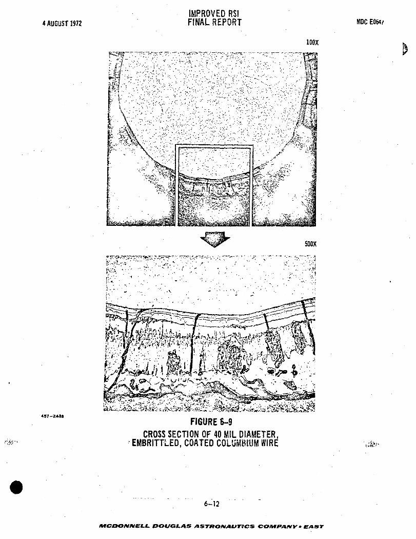
4 AUGUST 1972IMPROVED RS!FINAL REPORT MDC EOW/
100X
500X
.
437-2438
FIGURE 6-9CROSS SECTION OF 40 MIL DIAMETER,
EMBRITTiED, COATED COLliMBftlM WIRE
6-12
MCOKtNNELt. DOUGLAS ASTKOIVAUTICS COMPANY * EAST

c
IMPROVED RSI4 AUGUST 1972 FINAL REPORT HDCE0547
Figure 6-10. A complete visual and X-ray inspection revealed no voids, cracks,
or inclusions. However, during repair of a defect in the coating on the columbium
wire array, the HCF block developed a crack, probably due to the wire rapidly con-
ducting the heat to the interior and causing internal stresses and the cracking.
The type of localized heating used to effect the repair is not representative of
an actual Shuttle use.
Modified Columbium Wire Array - A columbium wire array of modified design was
fabricated as shown in Figure 6-11. The objective of this design was to optimize
4S72966
: FIGURE 6-10 -:-#-FULL DEPTH COLUMBIUM WIRE REINFORCED HCF AFTER
FIVE CYCLES AT 2300°F/2500°F
6-13
ATOOO/V/VfLL DOUGLAS ASTftOfVAUTICS COMPANY • EAST

4 AUGUST 1972
IMPROVED RSIFINAL REPORT MDC E0647
497-2934
FIGURE 6-11MODIFIED COLUMBIUM WIRE ARRAY
6-14
MCDONNELL DOUGLAS ASTRONAUTICS CO/VffA/WV - EAST
IMPROVED RSI4 AUGUST 1972 FINAL REPORT MDCE0647
the reinforcement by eliminating some unnecessary trusses and supports, while better
distributing the loads at the attachment points.
6.5 THERMAL RESPONSE TO FULL-DEPTH COLUMBIUM WIRE REINFORCED HCF SPECIMEN -
The full-depth columbium wire reinforced HCF specimen was exposed to five thermal
cycles. The first four cycles peaked at 2300°F and the last at 2500°F (Figures
6-12 and 6-13). The specimen was inspected between and during test cycles for
crack propagation and growth. The crack induced during processing did not grow
and no further cracks were observed. It may be concluded that the columbium wires
successfully reinforced the specimen by inhibiting crack growth.
In an attempt to measure the magnitude of "heat shorts" due to the wire rein-
forcements, one chrome1-alumel thermocouple was placed on the bottom surface of
the culumbium fastener foot and another was placed on the cold face of the HCF
specimen in an area away from the wires. As shown in Figures 6-12 and 6-13, the
foot was cooler than the HCF in both the 2300°F and 2500°F cases. These results
were probably due to cooling from the 0.060-inch thick titanium face plate to which
the reinforcement pads were bolted and to small heat conduction paths from the hot
HCF tile to the attachment pads. From this test, the conclusion was drawn that
the "heat short" consideration in our reinforced HCF concept is negligible. This
is in agreement with earlier calculations which indicated a "heat short" of under
one percent.
6.6 STRENGTHENED AND REINFORCED HCF - As an outgrowth of the reinforced HCF
concept, an approach was conceived which could save considerable HCF thermal pro-
tection system weight.
This concept, shown in Figure 6-14, uses a truss system which transfers air
pressure loads to three attachment points. The trusses are welded to the finer
diameter wires which form the standard reinforcements. An early model using 0.035-
inch diameter stainless wire is shown in Figure 6-15.
6-15
/VfCOO/V/VELL DOUGLAS ASTirOMAllTICS COMf*AIW • EAST

4 AUGUST 1972IMPROVED RSIFINAL REPORT MDC E0647
L-COATED COLUMBIUM FASTENER FOOTI I I
16 20 24 28
TIME - MINUTES
FIGURE 6-12THERMAL RESPONSE OF COATED COLUMBIUM WIRE REINFORCED
HCF DURING FIRST CYCLE AT 2300°F
497-2539
6-16
DOUGLAS ASTftOMAtJTiC& CONIf ANY * EAST

4 AUGUST 1972IMPROVED RSIFINAL REPORT MDC E0647
c
497-2936
QUARTZLAMPS
HCF HOT FACE
Cr-ALUIYIEL T/C
HCF COLD FACE
COATED COLUMBIUM FASTENER FOOTi i i i
8 12 16 20 24 28 32 36
TIME - MINUTES
FIGURE 6-13
THERMAL RESPONSE OF COATED COLUMBIUM WIRE REINFORCEDHCF DURING FIFTH CYCLE AT 2500°F
6-17
MCDONNELL. DOUGLAS ASTRONAUTICS COMPANY • EAST

4 AUGUST 1972IMPROVED RSIFINAL REPORT KDC EOS47
0.010 IN.COLUMBIUM WIRE
(OR MINIMUMVKiCH CAN
BE WELDED)
0.035 IN. DIAMETERTRUSS (COLUMBIUM)
4-0.035 IN.DIAMETER
COLUMBIUMWIRES
457-1768
PLATE-NUT
-ALUMINUM
STRUCTURE
WELD ALL
/ INTERSECTIONS
STAINLESS
FOILPACKAGE;1400°FTO 1800°F MAX
EFFICIENT LOW
DENSITY THERMALINSULATION
FIGURE 6-14
STRENGTHENED AND REINFORCED HCF THERMAL INSULATIONPROTECTION SYSTEM
6-18
MCDONNELL. DOUGLAS ASTRONAUTICS COMPANY - EAST

4 AUGUST 1972IMPROVED RSIFINAL REPORT IfiDC E0647
FIGURE 6-15
EARLY MODEL OF WIRE TRUSS STRENGTHENING SYSTEM
457-1777
6-19
MCDONMELL. DOUGLAS ASTKOIVAtJTICS COMPAIWY . EAST

IMPROVED RSI4 AUGUST 1972 FINAL REPORT MDCE0647
The weight reduction is achieved by trading HCF very efficient low density
insulation between the reinforced HCF tile and the airframe.
6.7 SUMMARY OF REINFORCEMENT ACCOMPLISHMENTS - The accomplishments and
conclusions from the reinforcement effort are summarized below:
o Metal wires are the best reinforcement material; SiO- and ZrO~ threads
became brittle,
o Columbium (Cb-752) wires are better than nickel-chromium and platinum
because of thermal expansion compatibility with HCF and temperature
resistance,
o Wire reinforced HCF was felted, dried, and fired in the conventional
manner with no difficulty.
o A simplified welded array of wires with load distribution attachment
points has evolved,
o Reinforcement inhibited separation of cracked HCF during five thermal
cycles,
o The "heat short" consideration in wire reinforcement was proven to be
negligible during thermal cycling.
6-20
MCDONNELL DOUGLAS ASTHOA/AUTtCS COMfANY • EAST

IMPROVED RSI4 AUGUST 1972 FINAL REPORT MDCE0647
7.0 CONCLUSIONS AND RECOMMENDATIONS
The following conclusions and recommendations are based on the work performed
in this program and the related work in References (a) and (b) of Section 8.
7.1 Strength - Improvements can be made in the strength of mullite HCF
2material by control of the processing variables, with values of up to 250-lb/in
3in tension possible for 16-lb/ft material. Strength and modulus of elasticity
are dependent on density. The strength of HCF is anisotropic because of the
preferred orientation of the fibers.
7.2 Density - Average density can be controlled to 15 + 1-lb/ft from felt
to felt, and + 1 PCF within a single tile by formulation and processing control.
Each new fiber type and diameter, filler and binder material processes differently.
Various blending times and speeds, and resulting viscosities, are examples of the
types of parameters which must be adjusted and then controlled to produce good
quality felts. Also, various organic processing aids can be added to control the
quality and uniformity of the final products.
7.3 Thermal Performance - Thermal performance efficiency can be improved on
the order of 20 percent by substituting about 20 percent of smaller diameter, less
than 2-u fibers for standard 6-y diameter fibers.
Our Mod V composition, which is an 80-20 mixture of mullite and silica fibers,
offers the thermal performance improvement described above and possible higher
strength, compared to our Mod IIIA material. This is based on laboratory size
felts.
Small diameter (1.6-jj) aluminosilicate fibers (SKX type) have shown to be
efficient in thermal performance when tested in an HCF type formulation; however,
they are not as temperature resistant as mullite fibers.
Small diameter (2.5-y) mullite has also recently been produced by B&W, and
evaluated by us to a limited degree. These fibers should also be efficient thermal
insulators. j_-\
AfCOO/V/VEXf. DOUGLAS ASTRONAUTICS COMF*A*IY • EAST

IMPROVED'RSI4 AUGUST 1972 FINAL REPORT M5C E0647
Mixtures of fibers, such as silica and mullite, and combinations of fine and I
medium diameter mullite fibers, are areas in which RSI could be further improved.
7.4 Coatings - A smoother inorganic surface coating can be obtained by first
filling the HCF surface irregularities and then overspraying. The surface density
2of the coating can be decreased to 0.15-lb/ft by eliminating one layer of the
coating. This system still remains waterproof and reusable but its strain to
failure could not be increased.
The following areas are suggested for future work on coatings:
0 Develop a low modulus reusable inorganic coating that is sealed from
liquid water with an organic coating that would be refurbished after
entry. The inorganic coating would provide handling abrasion, resistance
when the organic coating is absent. This would eliminate the high
modulus glass seal coating that is a shortcoming of that type coatingN.
system.
0 Develop an inorganic glassy sealed coating that is self-healing. This
would provide waterproofing of cracked coating upon cool-down. The
present coating systems that provide this feature, blister at reduced
pressure and at temperatures around 2500°F.
0 Evaluate organic coatings that provide liquid waterproofing of the
gaps in the RSI tiles and that can be refurbished after different
temperature exposures up to 2500°F.
0 Evaluate organic impregnants which provide waterproofing for several
flights by pyrolysis/condensation mechanisms.
- - . - . - . - - 7 _ 2
/frfCDOA//VE(.£. DOUGLAS ASTRONAUTICS COMfA/VY • EAST

c:
IMPROVED RSI4 AUGUST 1972 FINAL REPORT MDCE0647
7.5 Reinforcements - Metal wires are an effective means of preventing the-
separation of cracked pieces of HCF and do not cause appreciable heat shorts.
Reinforced HCF can be made void free, by standard felting techniques. An increase
3in density of 1.5-lb/ft resulted from the use of a coated columbium wire reinforce-
ment.
This reinforcement effort led to the concept of strengthening HCF by including
metallic trusses in the HCF. When combined with the use of efficient low-density
insulation, these trusses could save up to 50 percent of the weight of an unreinforced
RSI thermal protection system.
7-3
/VfCDO/V/VE-f.1. DOUGLAS ASTRONAUTICS COM fAMY ' EAST

IMPROVED RSI4 AUGUST 1972 FINAL REPORT MDCE0647
8.0 REFERENCES
Reference (a) : High Temperature Insulation Materials for Reradiative Thermal
Protection Systems, MDC Report E0666, 19 July 1972.
Reference (b): Reusable Surface Insulation (RSI) Thermal Protection Development
for Shuttle, HDC Report E0557, Volume I, 21 March 1972.
C
8-1
/VIC >OIV/V£LL DOUGLAS ASTKOMAUTICS COI*lf*AfW • EAST

Page Intentionally Left Biank

^
DG9JGL.AS
Saint Louis. Missouri 63166 (314)232-0232
-EAST

Page Intentionally Left Blank