r eg n a tiv b yp ck s m model 17030 - chromaus.com · chroma's 17030 system include a driving...
TRANSCRIPT

Model 17030
Regenerative Battery Pack Test System
Chroma's 17030 is an automated regenerative test system specifically designed for high power battery pack tests. Accurate power sources and measurements ensure test quality suitable for repetitive and reliable testing of crucial battery packs. Applications include incoming inspections capacity validation, production and certification testing.
Chroma's 17030 system architec ture offers regenerative discharging designed to recycle the electric energy sourced by the battery pack. This feature saves electricity, reduces the facilities costs, reduces the thermal foot print and provides a green solution by reducing the environmental impact to the planet.
Chroma's 17030 system include a driving cycle simulation function. Since automotive battery packs are used at quick and irregular intervals, the 17030 incudes the capability to create seamless t ransit ions bet ween maximum charge and maximum discharge (or maximum discharge and maximum charge) with a rapid 50 ms conversion.
This feature allows for charge/discharge mode simulations of real world driving scenarios. The system simulates the real conditions on the battery pack in its working condition.
Chroma's 17030 system has �exible programming functions and includes Chroma's powerful Battery Pro software. Battery Pro is a user friendly software environment allowing for the creation of a wide range of test scenarios from basic charge and discharge to complex drive cycle testing. Battery Pro's features allows quick and intuitive test development to eliminate the need for tedious scripting or programming by a software developer.
There are multiple safety features built into the 17030 including battery polarity checks, overvoltage protection, overcurrent protection and over temperature protection. In the unlikely event of a power or computer communication loss, the data is securely stored within the system in non-volatile memory thereby protecting against potential data loss and allowing for continuous �ow after restart.
Key Features:█ Supports high power battery certification:
IEC, SAE, GB⋯etc.
█ Regenerative battery discharge, Saves energy,
environment-friendly and provides low heat
dissipation
█ Driving cycle simulator
█ Industry Leading Accuracy
█ 10ms Data acquisition
█ Charge / discharge mode
- Constant Current
- Constant Voltage
- Constant Power
█ Customized rating power
- Voltage range:10~1200V
- Current range:0~1000A
- Power range:90~350kW
█ System Integration:
- Chamber Control
- Multi-channels voltage/
temperature measurement (Max 192CH)
- BMS Communication
Ethernet
REGENERATIVE BATTERY PACK TEST SYSTEM MODEL 17030

Customized rated power17030 design allows for customized power levels. █ Channels are easily paralleled with same model to support higher current requirements. This feature provides ultimate flexibility between high channel count and high current testing. (Supports a maximum of 2 units)█ Dual output in one system, independent control
Regenerative Energy█ Regenerate power to grid, Low heat dissipation, reduce air-conditioner loads and facility power consumption█ THD under 5% at rated power█ The PF over 0.9 at rated power█ Efficiency above 85% when operated above 20% of rated power
Driving Cycle Simulation (Power/ Current Waveform mode)Simulate real automotive working conditions by defining quick andirregular charging and discharging conditions.█ Import dynamic charge/discharge waveforms to simulate the DRIVE CYCLE or other actual applications via .xls file formats█ Supports 720,000 points within driving profile memory for saving profiles of each channel█ Minimum transition time (Δt) = 10ms
High accuracy capacity calculationVoltage/current sampling rate of 50kHz used for calculations of capacity ratings in current waveform mode. █ V/I sampling rate : 50KHz█ Minimum data acquisition: 10ms █ Integrate calculus : For I : Capacity, - For V x I : Energy
System FunctionCharge / discharge mode█ Constant Current/Constant current- limited Voltage/Constant Power█ Waveform current mode█ DCIR mode (IEC61960-2004)█ Rest mode
Cut-off condition█ Time/ Capacity/ Voltage/ Current/ Temperature█ Data Acquisition from data logger (option)█ Data Acquisition from BMS (option)
Protection█ OVP/UVP/OCP/OTP/OQP█ Data Acquisition from data logger (option)█ Data Acquisition from BMS (option)█ Turn the main loop off for safety issues of AC line█ ΔV protection / ΔI protection for internal short of battery pack█ ΔV period protection / ΔI period protection█ CC-CV transition time
Testing Data█ Generate the detailed report and step report█ Customized report format
Continuous transition█ Continuous charge and discharge transition: No time delay to transit from charge to discharge█ Continuous CC-CV transition: No overshoot current or voltage which may damage the battery when transiting modes
Response time█ The trip time between maximum charge and maximum discharge current in static modes is 50ms. (10mS in waveform mode)█ Smooth current profiling without overshoot to avoid damage the battery
Data Recovery Function█ 60 min of temporary data storage when sampling time is 1 sec█ Automatic data recording in non-volatile memory allows for resumption of testing following power interruption
Temperature Measurement█ Temperature measured for each channel within the range of 0~90℃±2℃█ Maximum 4 thermal sensors can be connected in series for measuring 4 independent battery points█ Data Acquisition for temperature protection
KEY SYSTEM FEATURES
Regenerate the energy to AC line
DST Power Profile
Loading DST waveform current
Support FUDS test
Loading FUDS waveform current
Other Cycler Double Integrating Method
Sampling rateCatch the V/I pre 20us
Feedback the V/I pre 10ms
Sampling rate
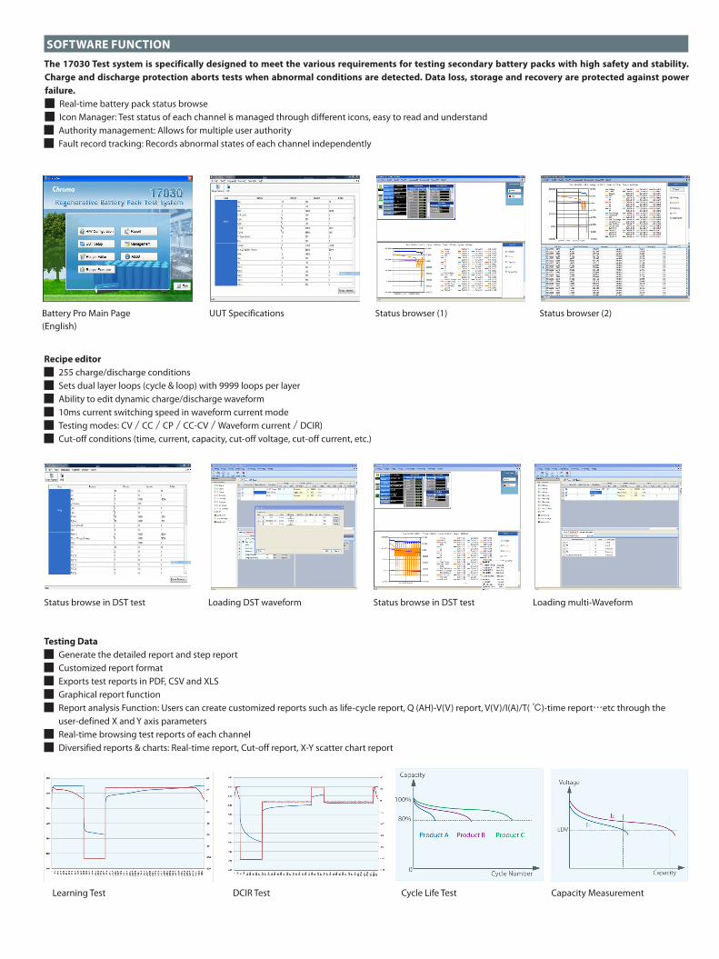
SOFTWARE FUNCTIONThe 17030 Test system is specifically designed to meet the various requirements for testing secondary battery packs with high safety and stability. Charge and discharge protection aborts tests when abnormal conditions are detected. Data loss, storage and recovery are protected against power failure.█ Real-time battery pack status browse█ Icon Manager: Test status of each channel is managed through different icons, easy to read and understand█ Authority management: Allows for multiple user authority█ Fault record tracking: Records abnormal states of each channel independently
Recipe editor█ 255 charge/discharge conditions█ Sets dual layer loops (cycle & loop) with 9999 loops per layer█ Ability to edit dynamic charge/discharge waveform█ 10ms current switching speed in waveform current mode█ Testing modes: CV/CC/CP/CC-CV/Waveform current/DCIR)█ Cut-off conditions (time, current, capacity, cut-off voltage, cut-off current, etc.)
Testing Data█ Generate the detailed report and step report█ Customized report format█ Exports test reports in PDF, CSV and XLS█ Graphical report function█ Report analysis Function: Users can create customized reports such as life-cycle report, Q (AH)-V(V) report, V(V)/I(A)/T( ℃)-time report⋯etc through the user-defined X and Y axis parameters█ Real-time browsing test reports of each channel█ Diversified reports & charts: Real-time report, Cut-off report, X-Y scatter chart report
Battery Pro Main Page (English)
UUT Specifications Status browser (1) Status browser (2)
Status browse in DST testStatus browse in DST test
Capacity MeasurementDCIR Test
Loading DST waveform
Cycle Life Test
Loading multi-Waveform
Learning Test

SOFTWARE INTEGRATION (OPTION)
█ Battery Pro can communicate to most thermal chambers for life and temperature testing .█ Many third party devices can be integrated into the 17030 via standard interface protocols (discrete I/O interface, GPIB, etc).
█ BMS communication interface: Collect Battery Management System data automatically during testing. -User types in the CAN massage -Convert DBC to Battery Cycler by Software Tools
█ Data logger: Data logger integration allows for detailed collection of voltage, current and temperature data during charge/ discharge profiling. -Support B, E, J, K, N, R, S, and T type thermal couples with ITS-90 defined temperature range -Individual channel cold junction compensation with <±0.3˚C accuracy -Temperature resolution up to 0.01˚C,error down to (0.01% of reading+0.3˚C) -Voltage full range ±10VDC;resolution 10uV; error down to 0.015% of reading+100uV -No matter how many channels are active, the data rate can be as fast as 5 samples per second per channel.
System configuration
17030
CAN
Ethernet
Entrance control
Many third party devices
RS485RS232
GPIB
Earthquake sensor
Chamber
V/I
Digital I/O
HF AC Tester
Ethernet
USB
Hi-Pot Test
Data logger Status browse Sample rate per channel = constant
BMS Status browse System configuration
Chroma's 64 channel data loogerModel 51101-64
System configuration
Convert DB Tools
CANbus messaging dialog box
Hub

* All specications are subject to change without notice. Please visit our website for the most up to date specications.
Safety Protection█ Channel monitoring icon: empty, contact checking, contact check failed, reverse polarity, standby, running, pause, finish, communication error, etc█ Save testing data when PC is down or disconnected█ Save the test settings to resume after the power failure is recovered
PROTECTION FUNCTION AND DATA RECOVERY
SPECIFICATIONS
Model 17030 *Channel 1 2 1 1 1 Max Power *1 90kW 180kW 180kW 210kW 210kW Max Power /Per channel 90kW 90kW 180kW 210kW 210kW Max Voltage 450V 450V 600V 700V 900V Max Current / Per channel 200A 200A 300A 300A 500A Constant Voltage Mode Voltage Range *2 13-450Vdc 15-450Vdc 16-600Vdc 15-700Vdc 19-900 Vdc Voltage accuracy 0.1%F.S. 0.1%F.S. 0.1%F.S. 0.1%F.S. 0.1%F.S. Voltage resolution 10mV 10mV 15mV 15mV 20mV Constant Current Mode Maximum Current 200A 200A 300A 300A 500A Current accuracy 0.2%F.S. 0.2%F.S. 0.2%F.S. 0.2%F.S. 0.2%F.S. Current resolution 10mA 10mA 15mA 15mA 20mA Constant Power Mode Max Power / Per channel 90kW 90kW 180kW 210kW 210kW Power accuracy 0.3%F.S. 0.3%F.S. 0.3%F.S. 0.3%F.S. 0.3%F.S. Power resolution 5W 5W 10W 15W 20W Current Rising Time (10% to 90% Load)
10ms with 0.2ΩResistive load
10ms with 0.2ΩResistive load
10ms with 0.2ΩResistive load
10ms with 0.2ΩResistive load
10ms with 0.2ΩResistive load
Ripple Noise (DC Current) <1%F.S. <1%F.S. <1%F.S. <1%F.S. <1%F.S. Overshoot <1%F.S. <1%F.S. <1%F.S. <1%F.S. <1%F.S. Measurement *3
Voltage Read Back range 0~450V 0~450V 0~600V 0~700V 0~900V accuracy 0.05% rdg.+0.05% F.S. 0.05% rdg.+0.05% F.S. 0.05% rdg.+0.05% F.S. 0.05% rdg.+0.05% F.S. 0.05% rdg.+0.05% F.S. resolution 10mV 10mV 15mV 15mV 20mV Current Read Back High range 0~200A 0~200A 0~300A 0~300A 0~500A accuracy ±0.1%F.S. ±0.1%F.S. ±0.1%F.S. ±0.1%F.S. ±0.1%F.S. Low range 0~50A 0~50A 0~75A 0~75A 0~125A accuracy ±0.2%F.S. ±0.2%F.S. ±0.2%F.S. ±0.2%F.S. ±0.2%F.S. resolution 10mA 10mA 15mA 15mA 20mA Power Read Back Power range 90kW 90kW 180kW 180kW 210kW Power accuracy ±0.2% F.S. ±0.2% F.S. ±0.2% F.S. ±0.2% F.S. ±0.2% F.S. Power resolution 5W 5W 10W 15W 20W Thermal Sensor range 0℃ ~90℃ 0℃ ~90℃ 0℃ ~90℃ 0℃ ~90℃ 0℃ ~90℃accuracy ±0.2℃ ±0.2℃ ±0.2℃ ±0.2℃ ±0.2℃resolution 0.1℃ 0.1℃ 0.1℃ 0.1℃ 0.1℃
AC Input Line voltage / Frequency *4 3Ø 200V/220V/380V/440V/480V ±5%, 47~63Hz Others Audible noise level (in 1m distance) Under 70dB E�ciency (Typical) 85% Interface *5 Ethernet Operation Temperature 0 ℃ ~ 40 ℃
Dimension (H x W x D) *6
Transformer 1111 x 813 x 686mm / 43.75 x 32 x 27 inch
1257 x 1041 x 813mm / 49.5 x 41 x 32 inch
1257 x 1041 x 813mm / 49.5 x 41 x 32 inch
1257 x 1041 x 813mm / 49.5 x 41 x 32 inch
1257 x 1041 x 813mm / 49.5 x 41 x 32 inch
Power Enclosure 2286 x 2007 x 609mm / 90 x 79 x 24 inch
2286 x 2007 x 609mm / 72 x 119 x 24 inch
2286 x 2007 x 609mm / 90 x 79 x 24 inch
2286 x 2007 x 609mm / 90 x 79 x 24 inch
2286 x 2007 x 609mm / 90 x 79 x 24 inch
Weight *7
Transformer approx. 465 kg /approx. 1025 lbs
approx. 710 kg /approx. 1560 lbs
approx. 640 kg /approx. 1400 lbs
approx. 710 kg /approx. 1560 lbs
approx. 710 kg /approx. 1560 lbs
Power Enclosure approx. 1140 kg /approx. 2500 lbs
approx. 1600 kg /approx. 3500 lbs
approx. 1140 kg /approx. 2500 lbs
approx. 1140 kg /approx. 2500 lbs
approx. 1270 kg /approx. 2800 lbs

SPECIFICATIONS
17030 : Regenerative Battery Pack Test System 90kW / 450V / 200A / 1CH17030 : Regenerative Battery Pack Test System 180kW / 450V / 200A / 2CH17030 : Regenerative Battery Pack Test System 180kW / 600V / 300A / 1CH17030 : Regenerative Battery Pack Test System 210kW / 700V / 300A / 1CH17030 : Regenerative Battery Pack Test System 210kW / 900V / 500A / 1CH17030 : Regenerative Battery Pack Test System 240kW / 900V / 400A / 1CH
17030 : Regenerative Battery Pack Test System 250kW / 700V / 500A / 1CH 17030 : Regenerative Battery Pack Test System 250kW / 700V / 600A / 1CH 17030 : Regenerative Battery Pack Test System 250kW / 900V / 500A / 1CHA170201: IPC for battery test systemA692003: Thermal sensor(0~90℃),sensor cable (30cm)51101-64: Data logger - 64 channel (option)
ORDERING INFORMATION
*1 Customized rated power: Voltage 10~1200V; max Current 1000A; Power 90~350kW*2 The output range of voltage is referred by the cabling. The connection between the device and battery is 3 meters long as standard accessory.*3 20us sampling rate for calculating battery capacity and energy*4 The transformer is for isolation and to accommodate various facility voltages
*5 The interface from PC to 17030 is through Ethernet*6 The dimension is for reference. The dimensions are subject to change base on real condition*7 The weight is for reference. The weight are subject to change base on real condition
Model 17030 *Channel 1 1 1 1 Max Power *1 240kW 250kW 250kW 250kW Max Power / Per channel 240kW 250kW 250kW 250kW Max Voltage 900V 700V 700V 900V Max Current / Per channel 400A 500A 600A 500A Constant Voltage Mode Voltage Range *2 40-900 Vdc 15-700Vdc 10-700Vdc 10-900Vdc Voltage accuracy 0.1%F.S. 0.1%F.S. 0.1%F.S. 0.1%F.S. Voltage resolution 20mV 15mV 15mV 20mV Constant Current Mode Maximum Current 400A 500A 600A 500A Current accuracy 0.2%F.S. 0.2%F.S. 0.2%F.S. 0.2%F.S. Current resolution 20mA 20mA 30mA 20mA Constant Power Mode Max Power / Per channel 240kW 250kW 250kW 250kW Power accuracy 0.3%F.S. 0.3%F.S. 0.3%F.S. 0.3%F.S. Power resolution 20W 15W 20W 20W
Current Rising Time (10% to 90% Load) 10ms with 0.2ΩResistive load
10ms with 0.2ΩResistive load
10ms with 0.2ΩResistive load
10ms with 0.2ΩResistive load
Ripple Noise (DC Current) <1%F.S. <1%F.S. <1%F.S. <1%F.S. Overshoot <1%F.S. <1%F.S. <1%F.S. <1%F.S. Measurement *3
Voltage Read Back Range 0~900V 0~700V 0~700V 0~900V Accuracy 0.05% rdg.+0.05% F.S. 0.05% rdg.+0.05% F.S. 0.05% rdg.+0.05% F.S. 0.05% rdg.+0.05% F.S. Resolution 20mV 15mV 15mV 20mV Current Read Back High range 0~400A 0~500A 0~600A 0~500A Accuracy ±0.1% F.S. ±0.1%F.S. ±0.1%F.S. ±0.1%F.S. Low range 0~100A 0~125A 0~150A 0~125A Accuracy ±0.2% F.S. ±0.2%F.S. ±0.2%F.S. ±0.2%F.S. Resolution 20mA 20mA 30mA 20mA Power Read Back Power range 240kW 250kW 250kW 250kW Power accuracy ±0.2% F.S. ±0.2% F.S. ±0.2% F.S. ±0.2% F.S. Power resolution 20W 15W 20W 20W Thermal Sensor Range 0℃ ~90℃ 0℃ ~0℃ ~90℃ 0℃ ~90℃ 0℃ ~90℃Accuracy ±0.2℃ ±0.2℃ ±0.2℃ ±0.2℃Resolution 0.1℃ 0.1℃ 0.1℃ 0.1℃ AC Input Line voltage / Frequency *4 3Ø 200V/220V/380V/440V/480V ±5%, 47~63Hz Others Audible noise level (in distance) Under 70dB E�ciency (Typical) 85% Interface *5 Ethernet Operation Temperature 0 ℃~ 40 ℃
Dimension (H x W x D) *6
Transformer 1257 x 1041 x 609mm / 49.5 x 41 x 32 inch
1257 x 1041 x 813mm / 49.5 x 41 x 32 inch
1257 x 1041 x 813mm / 49.5 x 41 x 32 inch
1257 x 1041 x 813mm / 49.5 x 41 x 32 inch
Power Enclosure 2286 x 2007 x 609mm / 90 x 79 x 24 inch
2286 x 2007 x 609mm / 90 x 79 x 24 inch
2286 x 3023 x 609mm /90 x 119 x 24 inch
2286 x 3023 x 609mm /90 x 119 x 24 inch
Weight *7
Transformer approx. 870 kg /approx. 1900 lbs
approx. 705 kg /approx. 1550 lbs
approx. 705 kg /approx. 1550 lbs
approx. 705 kg /approx. 1550 lbs
Power Enclosure approx. 1250 kg /approx. 2700 lbs
approx. 1250 kg /approx. 2700 lbs
approx. 1250 kg /approx. 2700 lbs
approx. 1250 kg /approx. 2700 lbs
Distributed by:
Worldwide Distribution and Service Network17030-E-201406-PDF
CHINACHROMA ELECTRONICS(SHENZHEN) CO., LTD.8F, No.4, Nanyou Tian AnIndustrial Estate, Shenzhen,China PC: 518052Tel: +86-755-2664-4598Fax: +86-755-2641-9620
Developed and Manufactured by :CHROMA ATE INC. 致茂電子股份有限公司HEADQUARTERS66 Hwaya 1st Rd., KueishanHwaya Technology Park,Taoyuan County 33383,TaiwanTel: +886-3-327-9999Fax: +886-3-327-8898http://www.chromaate.comE-mail:[email protected]
JAPANCHROMA JAPAN CORP.472 Nippa-cho, Kouhoku-ku,Yokohama-shi, Kanagawa,223-0057 JapanTel: +81-045-542-1118Fax: +81-045-542-1080http://www.chroma.co.jpE-mail:[email protected]
U.S.A.CHROMA ATE INC. (U.S.A.)7 Chrysler Irvine, CA 92618Tel: +1-949-421-0355Fax: +1-949-421-0353Toll Free: +1-800-478-2026http://www.chromaus.comE-mail: [email protected]: [email protected]
CHROMA SYSTEMSSOLUTIONS, INC.19772 Pauling, Foothill Ranch,CA 92610Tel: +1-949-600-6400Fax: +1-949-600-6401http://www.chromausa.comE-mail: [email protected]
EUROPECHROMA ATE EUROPE B.V.Morsestraat 32, 6716 AH Ede,The NetherlandsTel: +31-318-648282Fax: +31-318-648288http://www.chromaeu.comE-mail: [email protected]