r. ramesh - arpa-e · p sat p r p -v c v v p sat = saturation polarization p r = remanent...
TRANSCRIPT

R. Ramesh
Departments of Materials Science & Engineering and Physics University of California, Berkeley
Materials Science Division, Lawrence Berkeley National Laboratory

Background
Epitaxial heterostructures as model systems Role of defects
Reliability and Yield
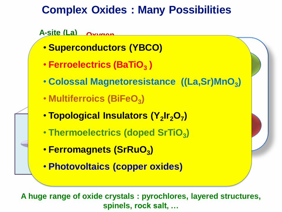
A huge range of oxide crystals : pyrochlores, layered structures,
spinels, rock salt, …
Complex Oxides : Many Possibilities
A-site (La) Oxygen
B-site
(Mn)
eg
t2g
charge
spin
orbital
lattice
• Superconductors (YBCO)
• Ferroelectrics (BaTiO3 )
• Colossal Magnetoresistance ((La,Sr)MnO3)
• Multiferroics (BiFeO3)
• Topological Insulators (Y2Ir2O7)
• Thermoelectrics (doped SrTiO3)
• Ferromagnets (SrRuO3)
• Photovoltaics (copper oxides)

Energy Conversion/
Transduction
Field Tunable Photonic
Bandgap Structures
Information Storage
Radiation Sensing
Energy Storage
I. Interface-mediated
functionality
spin charge
lattice orbital
II. Functional interfaces

BiFeO3
Rhombohedral, R3c
ahex = 5.58 Å; chex = 13.86 Å
a = 3.96Å, ar = 0.6°
(a) (b)
(c)
MFe2
[111]
MFe1
M
(d)
G-type
Antiferromagnetic
Order
Weak
Ferromagnetic
Moment
Bismuth Ferrite, BiFeO3: Model Multiferroic

Mn3+ -- O2- -- Mn4+
--- what’s the coupling mechanism at the interface ?
--- Role of Orbital physics ?
--- can we use an electric field to control this coupling ?
Fe3+ -- O2- -- Mn3+
Fe3+ - -- O2- -- Fe3+
Fe3+ -- O2- -- Mn4+
Bi Bi O
O O Fe
O
Fe
Mn Mn O O
La Sr O O
???
Interfaces III: Artificial Interfaces

Creating and Understanding Interfaces
MBE
e.g., Schlom Group
• Highly controlled growth
• Extremely high structural
quality
Oxygen
gas
Laser-in
RHEED
screen
Target
carousel
Substrate
holder &
manipulator
Ion
source
MSRI
reflectron
DRS RHEED, TOF-ISARS
• Highly controlled growth
• Interface chemistry
Laser-MBE
• Highly controlled
growth
• Controlled interfaces
Phosphor screen
+ CCD camera
Heater with substrate
Target holder
Laserbeam
Electron gun
2-stage differentially pumped
to main turbo pump

Atomic Control of Oxide Heterostructures
J. Huijben,…, D. Blank, Univ. of Twente

2 μm
AFM:SrTiO3
Termination Engineering: B site termination
Sr O O O Sr Sr O Sr
Ti O O O Ti Ti O Ti
Ti O O O Ti Ti O Ti
La O O O Sr La O Sr
Mn O O O Mn Mn O Mn
La O O O Sr La O Sr
Mn O O O Mn Mn O Mn
All Oxide Interfaces : BFO/LSMO

Termination Engineering: A site termination
Sr O O O Sr Sr O Sr
Ti O O O Ti Ti O Ti
Ti O O O Ti Ti O Ti
Sr
O
Sr
O
Ru
O
O
Ru
O
O
Ru
O
Sr
O
Sr
Sr
O
Sr
O
Ru
O
Sr
O
Sr
O
Sr
Ru
O
Ru
O
Ru
O
O
Sr
O
Sr
Ru
O
O
Sr
La O O O Sr La O Sr
Mn O O O Mn Mn O Mn
La O O O Sr La O Sr
Mn O O O Mn Mn O Mn
Time Of Flight-Mass Spectroscopy of
Recoil Ion (TOF-MSRI)
Controlling Surface Termination

MSRI results for difference terminations Probing Surface Termination

BiO Interface La0.7Sr0.3O Interface
Atomic Structure of interfaces
SRO

La0.7Sr0.3O Interface BiO Interface
Structure and Composition of Interfaces (STEM-EELS)
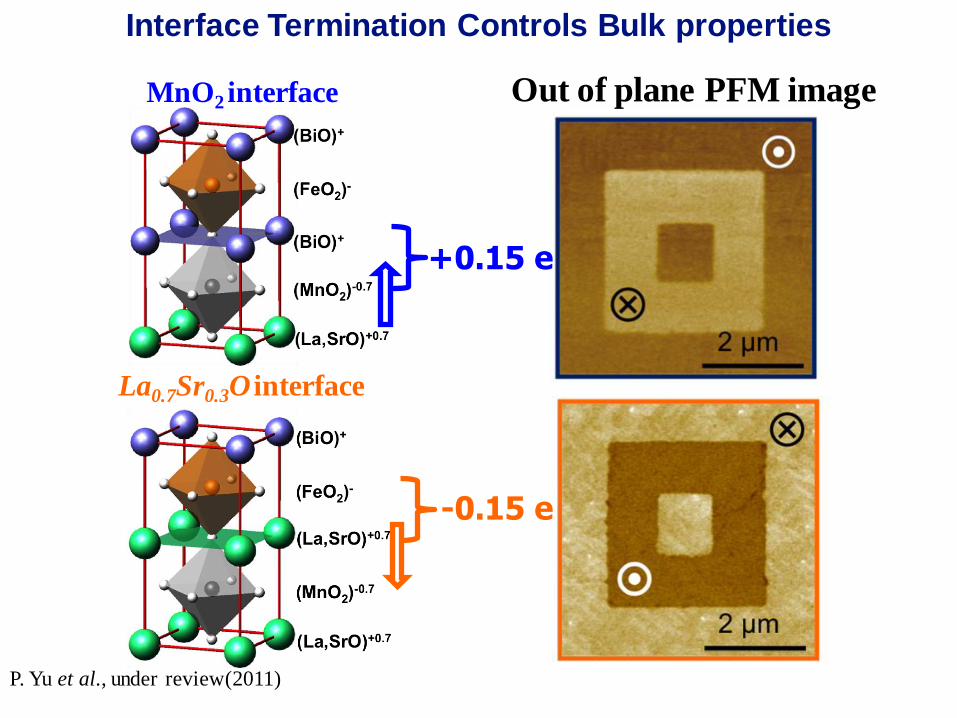
Interface Control of Bulk Ferroelectric Polarization
MnO2 interface
La0.7Sr0.3O interface
Out of plane PFM image
P. Yu et al., under review(2011)
+0.15 e
-0.15 e
Interface Termination Controls Bulk properties

BiO interface La0.7Sr0.3O interface
Experimental Probe of Interface Induced Potential Step.
Internal field: shift of piezoresponse hysteresis loop;
Interface induced electrostatic potential step ~ difference
between internal fields ~ 1.2 Volts.
Vint=0.66 V Vint=-0.55 V
Interface Termination Controls Bulk properties

0
20
40
60
0 2 4 6 8 10 12 14 16
-1.0
-0.5
0.0
0.5
1.0
P(
C/c
m 2)
Po
ten
tia
l (V
)
Supercell Index
P Right
P Left
Average
LSMO LSMO BFO
MnO2 LSO
First-Principle Calculations
Collaboration with Dr. Luo, W. D., Prof. Pennycook, S. J. and Prof. Pantelides, S.T. at ORNL.
Interface induced electrostatic
potential step ~1.3V
Interface Termination Controls Bulk properties

Exchange bias comparison of different interfaces
-800 -400 0 400 800-600
-400
-200
0
200
400
600
Mag
ne
tization
(em
u/c
c)
Magnetic Field (Oe)
5 nm LSMO + 75 nm BFO
FC 1T
FC -1T
5 nm LSMO
FC 1T
FC -1T
@10K
Bias Field ~ 40 Oe BiO Interface
O Fe O Fe
Bi Bi O O
O Mn O Mn
-1500 -1000 -500 0 500 1000 1500-600
-400
-200
0
200
400
600
Ma
gn
etiza
tio
n (
em
u/c
c)
Magnetic Field (Oe)
5 nm LSMO + 75nm BFO
FC 1T
FC -1T
5 nm LSMO
FC 1T
FC -1T
@10K
Bias Field ~ 200 Oe La0.7Sr0.3O Interface
O Fe O Fe
La Sr O O
O Mn O Mn
Exchange coupling changes with Interface termination!!

Probing Exchange Coupling with XMCD

Psat
PR
P
-VC VC V
Psat = Saturation polarization
PR = Remanent polarization
VC = Coercive voltage
Memory Parameter DRAM FeRAM
Min Max Min Max
Supply Voltage 3.15 V 3.45 V 3.15 V 3.45 V
Low Power Standby - - - 10 μW
Operating Active Current - 25 mA - 25 mA
Operating Temperature 0°C 70°C 0°C 70°C
Storage Temperature -55°C 125°C -55°C 125°C
Non-Volatile Data Storage - - 0°C 70°C
Read Cycle Time 50 ns - 50 ns -
Address Access Time - 26 ns - 26 ns
Read Cycles Per Byte >1015 - >1013 -
Write Cycle Time 50 ns - 50 ns -
Non-Volatile Data Retention - - - 10 yrs.
Write Cycles Per Byte >1015 - >1013 -
FeRAMs: Solving Technology Challenges through Science
Scott & Araujo, Science 246, 1400 (1989)
Imprint
Fatigue

New Approach –
LSCO/PNZT/LSCO
Old Process –
Fatigue is an issue
100 102 104 106 108 1010 1012
Fatigue Cycles
150
100
50
0
-50
-100
-150
Re
mn
an
t P
ola
rizati
on
μC
/cm
2
100 102 104 106 108 1010 1012
Fatigue Cycles
150
100
50
0
-50
-100
-150
Re
mn
an
t P
ola
rizati
on
μC
/cm
2
Binary Metallic Oxides
• IrO2
• RuO2
• PdO2
• OsO2
• ReO3
Metallic Perovskites
• (La,Sr)CoO3
• SrRuO3
• (La,Sr)MnO3
• YBa2Cu3O7
• Bi2Sr2CaCu2O8
• LaNiO3
LSCO
LSCO
PNZT/PLZT
100 102 104 106 108 1010 1012
30
20
10
0
-10
-20
-30
Epitaxial
Epitaxial
Oriented
Polycrystalline
Fatigue Cycles
Po
lari
zati
on
– Δ
P (
μC
/cm
2)
Oriented
Polycrystalline
Ramesh, et al., Science 252, 944 (1991)
Ramesh, et al., APL 61, 1537 (1992)
Eom, et al., Science 258, 1766 (1992)
Ramesh, et al., APL 63, 3592 (1993)
Kingon, et al., JMR 9, 2968 (1994)
Basic Science Solves Applied Problems

University of California, Berkeley Turnbull Lecture November 27, 2007 21
-15 -10 -5 0 5 10 15
40
30
20
10
0
-10
-20
-30
-40
Voltage (V)
Po
lari
zati
on
(μ
C/c
m2)
-12 -8 -4 0 4 8 12
30
20
10
0
-10
-20
-30
Voltage (V) P
ola
rizati
on
(μ
C/c
m2)
Pt/PZT/Pt LSCO/PZT/LSCO
Oxide Electrodes Solve the Imprint (Internal Field) Problem
Oxide Electrodes: Eliminate Imprint
Pike, et al., APL 66, 484 (1995) & Warren, et al., APL 67, 866 (1995)
60 70 80 9030
35
40
45
50
55
60
65
70
75
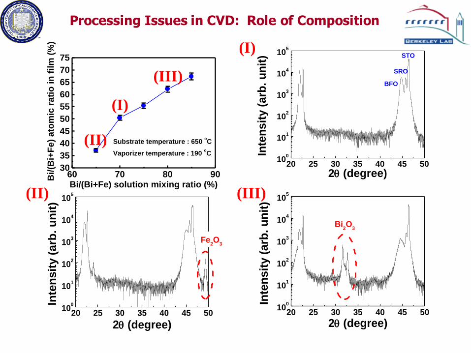
Substrate temperature : 650 oC
Vaporizer temperature : 190 oC
Bi/(B
i+F
e)
ato
mic
rati
o in
film
(%
)
Bi/(Bi+Fe) solution mixing ratio (%)
(I)
20 25 30 35 40 45 5010
0
101
102
103
104
105
STO
SRO
BFO
Inte
nsit
y (
arb
. u
nit
)
2 (degree)
(I)
(II)
20 25 30 35 40 45 5010
0
101
102
103
104
105
Fe2O
3
Inte
nsit
y (
arb
. u
nit
)
2 (degree)
(II)
(III)
20 25 30 35 40 45 5010
0
101
102
103
104
105
Bi2O
3
Inte
nsit
y (
arb
. u
nit
)
2 (degree)
(III)
Processing Issues in CVD: Role of Composition

Composition effect
Topography (33 m2)
Out-of-plane piezoresponse
Fe-rich Bi-rich
Need for careful composition control!!

SRO
BFO
High quality epitaxial BFO films
20 30 40 50 60
100
1k
10k
100kS
TO
(001)
BF
O (
001)
ST
O (
002)
BF
O (
002)
Inte
ns
ity
(c
ps
)
2 (deg.)
BFO
Si
STO
SRO

Possible conduction mechanisms
Schottky emission
Space charge limited conduction
Poole-Frenkel emission
Fowler-Nordheim
tunneling BFO
BFO
R E
E

0 1 2 3 4 5 6 7 8 9 101E-13
1E-12
1E-11
1E-10
1E-9
1E-8
1E-7
1E-6
Le
ak
ag
e [
A]
Voltage [V]
Positive
Negative
Leakage
Poole-Frenkel Emission : Fe3+ Fe2+ + h+
Schottky Emission
Electron Hopping : From Fe2+ to Fe3+
Space-Charge-Limited Conduction
0 2 4 6 8 10
1E-11
1E-10
1E-9
1E-8
1E-7
1E-6
1E-5
1E-4
d=240nm
A=8E-6cm2
Le
ak
ag
e C
urr
en
t [A
]
Applied Voltage [V]
20C (Positive) 20C(Negative)
40C 40C
60C 60C
80C 80C
100C 100C
Critical Issue #2 How to reduce leakage ?
Understand leakage mechanisms
Chemical doping
Area: 8e-6cm2

Identifying the leakage mechanism
0.5 1.0 1.5 2.0 2.5 3.0 3.51E-13
1E-12
1E-11
1E-10
1E-9
1E-8
1E-7
1E-6
V1/2
Positive
Negative
Co
nd
uc
tiv
ity
[
-1c
m-1
]
K=13
n=3.6
Poole Frenkel Plot
0.5 1.0 1.5 2.0 2.5 3.0 3.5
1E-8
1E-7
1E-6
1E-5
1E-4
1E-3
0.01 Positive
Negative
J/T
2 [
A/m
2K
2]
V1/2
K=1.6
K=4.3
n=2.07
Schottky Plot
The extracted dielectric constant is too high, about twice that of the expected 6.25-6.5
Poole-Frenkel
The extracted dielectric constant is too low for the negative direction, but not far off for higher fields
Schottky
Log-log plots (not shown) do not follow the expected trend
Space Charge Limited
Need more thickness, T and E dependent measurements