search.jsp?r=19800021209 2018-04 … rotor is supported on preloaded 5-shoe tilting pad bearings...
TRANSCRIPT

ANALYSIS AND IDENTIFICATION OF SUBSYNCHRONOUS VIBRATION
FOR A HIGH PRESSURE PARALLEL FLOW CENTRIFUGAL CO_iPRESSOR
R.G. Kirk, J.C. Nicholas, G.H. Donald, and R.C. Murphy
Ingersoll Rand Company
Easton, Pennsylvania 18042
SUI%_IARY
The evaluation of turbomachinery designs prior to actual hardware test
and field installation is now the rule rather than the exception for rotating
machinery manufacturers. This requires the verification of the current state
of the art analytical techniques for rotor-bearing-seal dynamics by development
testing and/or controlled test stand or field vibration studies. This paper
presents the summary of a complete analytical design evaluation of an existing
parallel flow compressor and reviews a recent field vibration problem that man-
ifested itself as a subsynchronous vibration that tracked at approximately 2/3
of compressor speed. The comparison of predicted and observed peak response
speeds, frequency spectrum content, and the performance of the bearing-seal sys-
tems are presented as the events of the field problem are reviewed. Conclusions
and recommendations are made as to the degree of accuracy of the analytical
techniques used to evaluate the compressor design.
INTRODUCTION
The design of dependable turbomachinery has always been of utmost impor-
tance in natural gas pipeline and petro-chemical installations. To meet this
challenge it is necessary for the designer of the turbomachinery to utilize
state of the art aerodynamic and mechanical vibration analytical prediction ca-
pabilities. Tremendous advances have been made in the past ten years in these
areas (ref. 1-8). Improved data retrieval and data reduction equipment make it
possible for mechanical vibration and aerodynamic pressure levels to be moni-
tored to assist in test stand design verification and/or the solution of field
problems in the event that they should occur (ref. 9-12). The correlation of
predicted to actual system behavior has been less than desirable in the area of
rotor-bearing system stability. This is especially true in regards to the pre-
diction of levels of destabilizing forces and the self-excited whirl frequencies.
It has generally been the rule that actual whirl frequencies are higher than
predicted frequencies for turbocompressors. Further complications arise when
the exact source or characteristic of an excitation cannot be categorized rela-
tive to prior operating behavior of turbocompressors.
The following paper will document such an occurrence for a particular de-
sign configuration of a single-stage, parallel flow compressor in a gas trans-
mission facility. The summary of the compressor rotor dynamics analysis will be
presented in addition to selected field data taken to characterize the vibration
before and after a successful field redesign to eliminate the source of the non-
synchronous excitation.
45
https://ntrs.nasa.gov/search.jsp?R=19800021209 2018-06-08T09:59:37+00:00Z

NOMENCLATURE
Values are given in both SI and U.S. Customary Units. The measure-
ments and calculations were made in U.S. Customary Units.
CB
Cp
CS
Cxx, Cxy,
Cyx, Cyy
D
Kxx, Kxy,
Kyx, Kyy
L
LB
M
N
1
NCR
PS
Q
Rv
Rp
U
WR
X,Y
Rv - R, tilt pad bearing assembled radial clearance in
line with a pivot (L)
Rp - R, pad radial clearance (L)
seal radial clearance (L)
bearing or seal damping coefficients (FTL -I)
journal diameter (L)
bearing or seal stiffness coefficients (FL -I)
bearing axial length (L)
bearing span (L)
I-(CB/CP) , tilt pad bearing preload
shaft rotational speed (RPM)
compressor first critical speed (RPM)
seal ring supply pressure (FL -2)
aerodynamic cross-coupling (FL -1)
radius from bearing center to pad surface in line with
a pivot (L)
pad radius of curvature (L)
imbalance (FL)
total rotor weight (F)
horizontal, vertical fixed coordinates
46

OPERATING HISTORY OF COMPRESSORS
The compressors that are the basis for this paper are similar to over 80
units in operation throughout the world with the same basic shaft and bearing
configuration. The compressors are driven through a flexible gear coupling by
an Ingersoll-Rand GT-22 power turbine which is rated at up to 4250 H.P. at a
max speed of 14,500 RPM. The units under discussion consist of 6 separate com-
pressors that may be operated either in series or isolated for closed loop
evaluation. The compressor configuration is shown in fig. 1 for parallel flow
operation. The rotor is supported on preloaded 5-shoe tilting pad bearings
with high pressure oil seal rings just inboard of the bearings as shown in fig.
2. The bearings are fed from the discharge of the outer seal ring and hence
the seals and bearings have a common lube oil system. All six units are design-
ed for purge gas injection for sour gas service while only three are typically
utilized for this service. The bearing and seal housings are close tolerance
double cartridge design to facilitate assembly and disassembly. The high pres-
sure loading locks the cartridge with several tons of axial loading and thus
assures a rigid interface to the compressor casing. The compressor rotor stage
configuration is indicated in fig. 3 where the parallel flow stages are shown
with the vaneless diffuser in cross-section. The stages are balanced aerody-
namically at inlet and discharge as a result of system symmetry about the center
diffuser ring.
Three of the compressors have been in service since 1973 with no major
vibration problem encountered prior to the spring of 1979. Tripout due to surge
related phenomena had occurred but the units were always capable of restart
without incident. Two additional units were shipped in late 1974 and the sixth
in mid-1978. The units will be denoted as 1-6. Unit Number 5 experienced vi-
bration problems at high speed and load which necessitated several rebuilds,
from December 1978 through May 1979, associated with coupling adjustments, im-peller fits, and bowed rotor induced imbalance. The rotor was locked in a 13
mil bow on one occasion which came straight upon disassembly. Rubs were notedon the latter runs of this unit.
Compressor Number 6 had been damaged on commissioning via foreign object
ingestion resulting in excessive vibration and rubbing on the impeller rims.
Compressor Number 2 had sustained damage in the seal area due to a lack
of cleanliness during reassembly which required that the shaft be built up by
chrome deposition in the seal area. Upon retrofit this unit began experiencing
vibration tripouts at high speed and load, but was capable of restart. As of
May 1979 two of the units, Nos. 1 and 3, were capable of continuous operation
without limitation, one of which had not been disassembled since shipment in
1973. Two units, Nos. 2 and 5, were experiencing tripouts but could be restart-
ed. The remaining units, Nos. 4 and 6, would vibrate such that restart was
questionable. This fact, being unsatisfactory to the customer and Ingersoll-
Rand, prompted action including analytical studies of the existing design using
latest analytical techniques, documentation of vibration and pulsation data on
site by both IR and consultants, and the examination of potential retrofit de-
signs for the rotor-bearing-seal system.
47

Vibration data had been taken and reduced in March of 1979 that revealed
a 2/3 rotative speed component of vibration that tracked with speed and came
into coincidence with another fixed frequency component at a frequency of ap-
proximately 140 Hz. This is shown in fig. 4 where the 2/3 component is noted
to appear above 200 Hz (12,000 cpm) rotor speed. The distinct frequencies are
shown more clearly in fig. 5 where the 2/3 component is coming into coincidence
to the fixed frequency. This figure does not have the line frequency (50 Hz)
and 3X line frequency interference as noted on the earlier data given in fig. 4.
The forced response for the same No. 6 Unit is given in fig. 6 for the
coupling and thrust end probe locations. This startup had a sequenced pressur-
ization and fast accel through the critical of approximately 124-129 Hz. The
units were typically started under full pressure which raised the peak response
frequency to 130-140 Hz as a result of the increased stiffness and damping from
the seal rings. This influence is indicated by the traces given in fig. 7
plotted for a portion of the accel. It is noted that the scales of figs. 6 and
7 are not all the same but the values of peak amplitude and frequency noted on
the traces were read from an RTA and give an accurate indication of the peak
response frequencies and _iplitudes.*
SUM)LARY OF ROTOR DYNAMICS ANALYSIS
The vibration problem as described in the previous section had not been
documented by any reference that was available to the knowledge of Ingersoll-
Rand or numerous consultants contacted concerning the nature of the field prob-
lem (ref. 14-20). The obvious potential sources - motors, pumps, power takeoffs
gas generator, etc., were investigated without a valid mechanical element in the
overall system design that could give the 2/3 x compressor speed forcing func-
tion. The thrust of the initial analytical investigation was therefore to con-
clude what could be modified in the bearing-seal system to improve the response
and stability of the compressor. This procedure was less desirable than elim-
inating the source of the excitation, but at that time the source was unknown.
The compressor was analyzed by in-house computer programs for bearing
analysis (ref. 5), seal dynamics (ref. 4), rotor response (ref. 13), and system
dynamic stability (ref. 7). The compressor shaft was initially modeled neglect-
ing the impeller shrink fits, which is in general the most conservative design
technique since added stiffness typically improves stability.
The undamped critical speed map for the 160 lb. rotor is given in fig. 8
including and neglecting the potential impeller fit stiffness. The fits were
more likely to add stiffness since the design was keyless and the fit was nec-
essary to transmit the horsepower. Fig. 8 indicates that the first critical can
be raised as much as 17 Hz (- i000 cpm) by the impeller fit since the midspan
position of the fits have a large influence on the first mode. Overplotted on
this map are the bearing characteristics for the minimum and approximate maximum
clearance for the current bearing design to be referred to as the new design.
* All experimental data presented in this report was very capably taken and
reduced by Mr. Terry Mitchell of Ingersoll-Rand, Wythenshawe, England.
48

The original units were shipped with a shorter pad and are referred to as theold design. The properties of these designs are given in table 1 for reference.Three compressors had the old design and three the new, but no correlationexisted between bearing type and severity of vibration. The unit with thelongest trouble-free operation had the old design bearings. However, anotherunit, No. 5, exhibited strong instability with the old design. The results ofthe analysis indicated the old design to be less desirable for stability.Since all current units utilize tile new design, tile analytical results hereinare for the new bearing design.
The rotor system was modeled including the influence of tile oil ringseals under design pressure and temperature conditions. For example, tableII gives the characteristics for the outer seal at N=208Hz (12,500 RPM)fora suction pressure of i000 psi.
Compressorshaving covered stages are considered to have little or nodestabilizing aerodynamic cross-coupling. The compressor stability or growthfactor is plotted in fig. 9 and indicates that a total level of over 10,O00ib/in could be tolerated for nominal design conditions without excessive exci-tation. The basic design has proven very stable in applications having morestages and hence higher design to ist peak response speed ratios. Classicalaerodynamic excitation is not knownto be characterized by a tracking component.
Figure I0 presents the stability of the compressor as a function of bear-ing preload. The solid curve is the new design and the preload range of 0.55to 0.7 is indicated to be acceptable. It should be noted that when the bearingswere designed the capability to predict stability was not available and hencethe judgement indicates good design practice. The dashed line has a betteroptimum stability and a preload range of 0.24 to 0.52 will result in tile optimumbearing configuration. This design is referred to as the redesign bearing (seetable I).
The response of the coupling end bearing is plotted in fig. ii for arange of bearing clearances showing that the compressor can experience a peakresponse, ranging from 108 Hz (6500 RPM)to 137 Hz (8200 RPM)depending on theactual build clearances in the compressors.
The influence of the seals on the response is indicated in fig. 12. Forcentered seals a single peak response at 112 Hz (6700 RPM)is indicated whereasthe more likely response would appear as a double peak with peaks occurring inthe range of 115 Hz-145 Hz (6900 RPM-8700RPM)without any account of impellerstiffness.
The influence of the seals' eccentricity on system dampednatural fre-quencies and stability is shownin fig. 13. The eccentric seal is noted tosplit the ist modefrom 2.8 Hz (168 cpm) to 26 Hz (1567 cpm) for maximumpres-sure at startup. The frequencies vary as a function of speed as indicated infig. 14. It is noted that one dampedcritical tracks with little change infrequency at near 130 Hz (7800 cpm) while the lower dampedcritical also remainsreasonably fixed in frequency but becomesless stable at higher speeds. _ilethe higher frequency modeis indicated to be backward, tile response study offig. 15 clearly illustrates that both these modesare excited by a forward
49

rotating excitation for bearing and seal characteristics fixed at values forN=225Hz (13,500 RPM)whereas on runup the only modeexcited is the higher(backward) mode.
A summaryof the bearing optimization study is presented in figs. 16 and17 for the new and redesign bearings (reference table I). The forward modesare noted to optimize for the nominal redesign bearings with a seal ring groove,whereas the newbearing design is best for tile condition of no seal ring groove.Further, while the redesign bearings can be optimized, the potential oversizeclearance condition is indicated to be more severe for the redesign bearings.
The results of a stability study, wherein the rotor system was artifi-cially stiffened to match the forward modeto the 140 Hz frequency are presentedin figs. 18 and 19 for the new and redesign, nominal bearing conditions. Theplots are given as growth factor versus aerodynamic excitation with the conclu-sion being that tile redesign nominal condition is far superior to the new bear-ing design. The stabilizing influence of the seals on system stability is alsoindicated by these plots. This is characteristic of rotors operating below 2.2times tile rotor first peak response frequency (ref. 4).
Consideration was given, following recommendationsfrom the customer, topossibly overboring tile impeller and retrofitting a larger diameter shaft in anattempt to improve the overall system rotor dynamics. The compressor design isnow and was always considered to be acceptable for normal levels of aerodynamicexcitation. The present design is noted to be at a N/Ncr ratio of less than 1.7which puts this compressor out of the class of tile original Kaybob (N/Ncr ~ 2.8)and Ekofisk (N/Ncr ~ 2.2) designs (see refs. 9 and ii). It is noted that tileEkofisk redesign shaft moved the critical from 48%to 66%of rated speed. Thepresent design places the critical at 60%of design speed.
With this background the concept of a stiffer shaft for the compressorseemsinconsistent with past experience. An improvement in stability is pre-dicted as would be expected but the once-per response levels and minimumspeedrange would be greatly influenced as noted by the response results of fig. 20.These response levels maybe scaled linearly to approximately 2.0 mils for in-creased levels of imbalance. It is evident that the once-per response level at13,000 rpm will be increased by 255%for nominal bearit_g clearances with thepeak response speed occurring as high as ii,000 rpm.
With the above facts indicating a very possible degradation of designspeed response and only a marginal improvement in stability, the concept of thestiffer shaft was considered as an absolute last resort redesign consideration.
The following section will summarizethe redesign steps and results thatparalleled the analytical studies briefly reviewed in this section.
50

SUM_h\RY OF FIELD MODIFICATIONS AND CONCLUSIONS OF OUTSIDE CONSULTANTS
The analytical study summarized in the previous section was paralleled
with field modifications and discussions with major turbomachinery consultants.
The basic conclusion of the consultants was that the analytical studies were
state of the art and only selected checks were run on the basic model to con-
firm the results. In addition, no occurrence of the 2/3 tracking phenomena was
known to any of the consultants engaged.
Initial field variations in hardware consisted of changing out rotors and
impellers to assure that an impeller blade rework to remove a casting problem
on the leading edge blades of the original compressor stages was not responsible
for the superior response of the original units. No correlation was found to
this small difference and the severe tripouts.
As mentioned previously, the original units were fitted with shorter,
lower preload bearings but no correlation could be made relative to bearing
type and the sensitivity to the nonsynchronous excitation.
The analysis indicated that removing the circumferential groove from the
outer seal ring would improve the dynamic performance. This was tried and the
result was affirmative but not sufficient to control the nonsynchronous forcing
mechanism.
Prior test stand experience indicated light rubs could reexcite the first
critical on this type compressor. For this reason, and since deep grooving was
noted in the buffer gas laby babbitted surface, the laby clearance was increased
to assure that no rub was occurring before tripout. After the laby clearance
was increased, the compressor spectrum was noted to be substantially cleaner
but the 2/3 component was still present and the units were speed limited.
As mentioned earlier, the stages were not keyed but relied on the shrink
fit for torque transmission. Some concern existed for a possible internal
friction mechanism at the impeller-shaft interface since these fits were at
midspan, the most sensitive position for reexcitation of the ist critical.
Also of concern, but without any analytical grounds for verification, was tile
stage spacing and the design of the center ring diffuser (see fig. 3). These
concerns were overshadowed by possible excitation from reflected pressure pul-
sation from either inlet or discharge (see fig. i) and the potential for a
rotating stall cell in the inlet or rotating stall in the vaneless diffuser.
The latter concerns were proven to be of no consequence by dynamic pres-
sure pulsation data taken in the piping, the inlet area of the stages, and the
diffuser. No evidence of pulsations that tracked or correlated to the vibra-
tion was detected in the No. 5 compressor instrumented with internal dynamic
pressure transducers. Additional piping pressure pulsation data were taken on
other units without any correlation to the forcing frequency.
At the same time an order was placed for the redesign bearing, the No. 6
compressor was modified to a keyed shaft with reduced fits, and the center
diffuser inside diameter was dropped to improve stage isolation. Additionally,
51

the cavity was pressurized to force flow radially up the back sides of the
stages. The result of this modification was the elimination of the 2/3 forcing
frequency. Upon replacement with an original impeller shaft configuration the
2/3 component was still absent.
At this time tile redesign bearings were tried in compressor No. 5 in
addition to another trial of the old style bearings. The critical was noted
to drop in speed from 135 Hz (8100 RPM) to 122 Hz (7350 RPM) after a shutdown
and immediate restart. As much as 0.25 mil subsynchronous was still present
at a frequency of 130 Hz (7800 cpm).
RESULTS OF FINAL DESIGN }_DIFICATIONS
The events of the field retrofits and analysis resulted in a decision to
use the original, keyless shaft with the new bearing design and grooveless seal
rather than the redesign bearings and grooved seal. In addition, the diffuser
was dropped and the center cavity pressurized to discharge pressure. This con-
figuration was installed in two other compressors in addition to No. 6 (No. 2
and No. 5) with the result being the elimination of the 2/3 component and only
a very small level of fixed frequency sub-synchronous vibration (0.05 mil max.
typical). The No. 2 compressor was speed limited due to balance, initially.
_4hen this was corrected, the speed limit was removed. All units were then
capable of going the full speed range without encountering sub-synchronous vi-
bration levels in excess of acceptable or tolerable levels. The compressors
with the modified diffusers have no 2/3 component while the unmodified compres-
sors are not speed limited, but do have a small 2/3 component that is detectable
but remains bounded.
The frequency spectrum before and after the final design modification for
compressor No. 5 is given in figs. 21 and 22, respectively. The improved low
level of fixed frequency is acceptable to both Ingersoll-Rand and the customer.
CONCLUSIONS
The following conclusions have been reached from a critical review of the
design evaluation and field vibration performance of the six single-stage,
parallel flow compressors discussed in this report:
I. Complex turbomachinery can be modeled to the necessary accuracy to study
response sensitivity if all impeller fits, bearing clearances, seal clearances,
and balance levels are known.
2. It is practical to do a design optimization to study design variation trends
without achieving exact agreement between predicted and actual measured levels
for damped frequencies.
3. Achieving bearing optimization in production bearings requiring less than
1/2 mil total variation in radial clearance at assembly is impractical and im-
possible to achieve in reality.
52

4. Compressorshaving oil seals and tilting pad bearings should have the bear-ing designed with a minimumpreload value greater than about 30%for the beststability characteristics.5. Zero or low preload tilting shoe bearings used in compressors having oilseals are more susceptible to oil seal or aerodynamic excited shaft whip thanhigher preload designs.6. High pressure compressors utilizing oil seals and operating below 2.2 -12.5 x Ncr can have increased stability and improved forced response sensitivitywith eccentric seals as compared to centered seals.7. Oil seals can alter the peak response speed of compressors by as muchas30 Hz with likely variation during startups on the order of i0 Hz.8. Both forward and backward analytically predicted dampednatural modescanbe excited by forward rotative forcing mechanisms.I9. Compressorsoperating below 1.8 x Ncr cannot have substantial improvementsin overall dynamic sensitivity by increasing the rotor shaft stiffness. Thisis especially true when a speed range is desirable from 80-100%design speed,for instance.i0. A forcing function mechanismhas been proven to occur in parallel flow com-pressors due to the spacing and flow of high pressure gas in the space and onthe back sides of the double flow stages. The detected mechanismproduced a2/3 x compressor speed excitation that can produce large level subsynchronousvibration when this frequency of excitation coincides with a system naturalfrequency.ii. A successful solution to the 2/3 x speed forcing componentwas arrived atby combined field tests, analytical work, and engineering judgement.
REFERENCES
I. Lund, J.W., "Stability and DampedCritical Speedsof a Flexible Rotor inFluid-Film Bearings", Journal of Engineering for Industry, Trans. ASME,Series B, Vol. 96, No. 2, May 1974, pp. 509-517.
2. Lennemann,E., and IIoward, J.H.G., "Unsteady Flow Phenomenain RotatingCentrifugal Impeller Passages", Journal of Engineering for Power, Trans.ASME,January, 1970, pp. 65-72.
3. Dussourd, J.L., et al, "An Experimental Investigation of the Control ofSurge in Radial CompressorsUsing Close Coupled Resistances", Journal ofFluids Engineering, Trans. ASME,March, 1977, pp. 64-75.
4. Kirk, R.G., and Miller, W.H., "The Influence of High Pressure Oil Seals onTurbo-Rotor Stability," ASLETrans., Voi.22, No.l, Jan. 1979, pp. 14-24.
5. Nicholas, J.C., Gunter, E.J., and Barrett, L.E., "The Influence of TiltingPad Bearing Characteristics on the Stability of High SpeedRotor-BearingSystems," Topics in Fluid Film Bearing and Rotor Bearing System Design andOptimization, an ASMEspecial publication, April 1978, pp. 55-78.
6. Lund, J.W., "Modal Responseof a Flexible Rotor in Fluid-Film Bearings",Journal of Engineering for Industry, Trans. ASME,Series B, Vol. 96, No. 2,May 1974, pp. 525-533.
53

7. Kirk, R.G., "Stability and DampedCritical Speed- Howto Calculate andInterpret the Results", CAGI, Technical Digest, Vol. 12, No. 2.
8. Nicholas, J.C., and Kirk, R.G., "Selection and Design of Tilting-Pad andFixed Lobe Journal Bearings for OptimumTurborotor Dynamics", Proceedingsof the 8th Turbomachinery Symposium,Texas A & M University, College Sta-tion, Texas, 1979, pp. 43-57.
9. Smith, K.J., "An Operation History of Fractional Frequency Whirl," Pro-ceedings of the Fourth Turbomachinery Symposium,Texas A & M University,College Station, Texas, 1975, pp. 115-125.
i0. Wachel, J.C., "NonsynchronousInstability of Centrifugal Compressors",ASMEPaper 75-Pet-22, Presented at Petroleum Mechanical EngineeringConference, Tulsa, Oklahoma, Sept. 21-25, 1975.
Ii. Booth, D., "Phillips' Landmark Injection Project", Petroleum Engineer,Oct. 1975, pp. 105-109.
12. Sparks, C.R., and Wachel, J.C., "Pulsations in Liquid Pumpsand PipingSystems", Proceedings of the 5th Turbomachinery Symposium,Texas A & MUniversity, College Station, Texas, 1976, pp. 55-61.
13. Lund, J.W., "Rotor Bearing DynamicsDesign Technology, Part V", AFAPL-TR-65-45, Aero Propulsion Laboratory, Wright-Patterson Air Force Base, Ohio,May 1965.
14. Jansen, W., "Steady Fluid Flow in a Radial Vaneless Diffuser", Journal ofBasic Engineering, Trans. ASME,Series D, Vol. 86, 1964, pp. 607-619.
15. Jansen, W., "Rotating Stall in a Radial Vaneless Diffuser", Journal ofBasic Engineering, Trans. ASME,Series D, Vol. 86, 1964, pp. 750-758.
16. Alford, J.J., "Protecting Turbomachinery from Self-Excited Rotor _irl",Journal of Engineering for Power, Trans. ASME,Series A, Vol. 87, Oct. 1965,pp. 333-344.
17. Nicholas, J.C., Gunter, E.J., and Allaire, P.E., "Stiffness and DampingCoefficients for the Five-Pad Tilting-Pad Bearing", ASLETrans., Vol. 22,No. 2, April 1979, pp. 113-124.
18. Black, H.F., "The Stabilizing Capacity of Bearings for Flexible Rotors withHysteresis," Journal of Engineering for Industry, Trans. ASME,Feb. 1976,pp. 87-91.
19. Kirk, R.G., and Gunter, E.J., "Non-Linear Transient Analysis of Multi-MassFlexible Rotors - Theory and Application", NASACR-2300, Sept. 1973.
20. Ferrara, P.L., "Vibrations in Very High Pressure Centrifugal Compressors",ASMEPreprint 77-DET-15, Presented at Design Engineering Technical Con-ference, Chicago, Illinois, Sept. 26-30, 1977.
54

Bearing
New
Old
Redesign
LCB M
in
(cm) mils (mm x 10 -.2 )
1.375 1.400(3.36) Min .70
t.49) 1.775(4.51) Nom .622.150(5.46) Max .55
2.000(5.08) Min .52 1.63i.O00
2,375(6.03) Nom .40 ,887
(2.54) 2.750(6.99) Max .27 .499
1.900(4.8 _) Min .52 3.141.375
(3.49) 2.275(5,78) Nora .38 ].622.650(6.73) Max .24 .785
N = 12,500 RPM
Kxx x 10 -5 Kyy x 10 -5 Cxx Cyy
ib/in (N/cm) 1b/in (N/cm) ib-s/in (N-s/cm) Ib-s/in (N-s/cm)
7.86 (13.76) 7.96 (13.94) 433 (758) 436 (764)
4.31 (7.55) 4.43 (7.76) 291 (510) 295 (517)
2.57 (4.50) 2.68 (4.69) 205 (359) 209 (366)
(2.85)
( I. 55)
(0.87)
(5.50)
(2,84)
(1.37)
1.88 (3.29)
1.20 (2.10)
.90 (1.58)
3.27 (5.73)
1.76 (3.08)
.979 (i.71)
131 (229)
98 (172)
76 (133)
277 (485)
204 (357)
159 (278)
142 (249)
114 (200)
99 (174)
283 (496)
212 (371)
172 (301)
D 2.75 in (6.985 cm) L/D = 1/2 (New, Redesign)
W R 160 Ibs (711.7 N) L B = 33 in (83.82 cm)
]ab[u [ (,e_mletr,/ ,iil([ dvn;Imi( char;tCt,,ristics %_r _ld, ilew, ;1114] redesi_u1 tire Mitre tilting-pad bearings
Seal
w/groove
w/o groove
Kxy x 10 -s
lb/tn
(N/cm)
i
7.86
(13.76)
4.85
(8.49)
Ky x x 10-s
ib/in
(N/cm)
i
-i.12
(-1.96)
-2.03
(-3.55)
Cxx
(ib-s/in)
(N-slc,.)
171
(299)
310
(543)
Cyy
(ib-s/in)
(N-s/cm)
1460
(2557)
717
(1256)
Lock-up
Eccentricity
.B4
.55
Kxx : Kyy = Cxy = Cy x = 0
C S : 4.0 mils radial (.1016 mm)
PS = i000 psi (689.4 N/cm 2)
N = 12,500 RPM
Table I1 I]il ring seal characteristics ior outer ring with and without circumferential groove
55

PARALLEL RRRAR|EIKHT
COMPREIOfl
Figure ] I'op view of a single stage parallel flow ct_rapressor confi_uration similar to the units discussed in the text
Figure 2 Cross-section of bearing-seal cartridge including, the buffer labyrinth
56
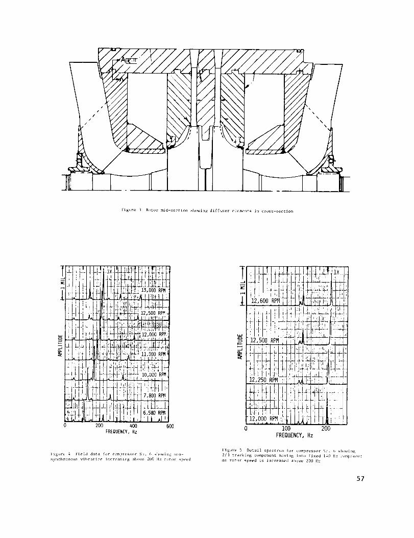
Figure 3 Rotor mid-section showing diffuser elements in cross-section
i0,000 RPM
600 0 I00 200
FREQUENCY, Hz
Figure 4 Field data for compressor No. 8 showing non-
synchronous vibration increasing above 200 tlz rotor speed
Figure 5 Detail spectrum for compressor No. B showing
2/3 tracking component moving into fixed 140 Fie compement
as rotor speed is increased above 200 Hz
57

END .__.__2_
PROBF--'_-_
!!,,NI---
22_i
' ' ,,t: 1_
COUPLINGEND PROBE"': I ! i i i Iii _
FREQUENCY
Figure 6 Peak imL[ response for a_,e_ trader step pres-
surization frnm 95 psi showing pc_lk resi!_msc, frequencies
of 124 and 129 Hz
--I
ili, II p_l;l ,
...... ,, T , ill _
-'. !l-,_:,d'! c!:t j/ik t,
COUPLINGENDPROBEI _,
I , t i '| I
FREQUENCY
Figure 7 P_,ak h_ld response for normal acce] und_-r full
pressure (HUU psi) _howirlg increased pe_k response lre-
q,_encies of 1{6 and 139 Hz
FOURTH
SINGLESTAGEPARALLELFLOWCOMPRESSOR
THIRD
/
I
CB:2.5MILS !M = ,47 i
1.75N/CM:I.O0_S/IN
i
I i
!i
r i I ,OPERATION I
CB = 1.4 MILS,M : ,7• i.I .i.lW/O IMPELLERSTIFFNESS i:
W/ IMPELLERSTIFFNESS
i0xI0a lOS i0_ i0r
SUPPORTSTIFFNESS _S/IN
Figure 8 Undamped critical speed map with and without impeller stiffness with new bearing characteristics overplotted
58

+20
- -20
u_
-qO
-6O
-8O
: : i STABLE!_ :"__ _1.75 N/CM : 1.00 LBS/IN : _ Fj.;."F_. '! -:.-: i-
' CB = 2.5 MILS, M = .47 _; ::_
I • 1 WITH IMPELLERSTIFFNESS.; ].
; i SEALS W/ GROOVE
i i I i l1 2 3 4 5
Q, AERODYNAMICCROSS-COUPLING,_S/IN PER WHEEL x 10-3
2OO
50
=2
-50
l . m • . - J ] 1
Q.o,o ,-12,_R_ T_:_--Z _-_- ____-W/O IRPELLER STIFFNESS ] .... r
150 -- W/ SBL GROOVE _ _ --_ --- _
FORWARD MODE .-_: --. _ ; _ __
4328 ; _ COt,ISTANT + . 7 --T_ -
i
-150 ............ : - - -
ii
-200 i - m i J i.i ,2 ,3 ,4 ,5 .6 .7
PRELOAI], M
E'igLJre 9 Stability map for standard design new bearings
_howing growth factor as a function of aerodynamic cross-
coupling per stage
Figure 10 Stability map for bearing design variations on
preload stlowing optimum for new design (C = 4.73 mils)P
and redesign bearings (CB = 2.5 mils)
U= 0,06OZ-INSEALS W/ GROOVE i
W/O IMPELLER STIFFNESS i
NEW BF.ARINGS
, I I_ I ,
,iI,!!/!l,!! i!fl! , l tI: I,;i V'_" .i"
]1, :,1 ,I, /,|t:",
2SPEED, R_ x i0"_
16
Figure il Coupling end response versus rotor speed for numerous bearing clearance values showing response levels
tncreasin_ above 8000 RI'M f_)r increased clearances
59

0 2 4 6 8 10 12 lqSPEED, RPMx 10-3
Figure 12 Coupling end response versds rotor si)eed fur numerous seal clearances alld ,)perating eccentricity ratios
.7 _-- _ ::-=_:
___ _-__Zii --; ...... ---'_---"
...... ; .
NEW BEAR I HGS
.2 __ NOIqI'b_LCLEARANCES
---_:_= Cs " q,O MILS RADIAL ±,
6738 6573 I___ N - 12,500 RPH.1
5739 5571J_ _ SEALS CENTERED :_ :_T: : -:0 " -- " "J
0 -20 -A¢ -60 -80 -100 -120
GROWTH FACTOR, S"x
Figure L3 Rotor system stability versus seal eccentricity
ratio for ne_ bearing showing improved stability for
increased seaI eccentricity
_I0
i
oo_o ._ FORWARD |
i WIO SEAL GROOVE _P -i BACKWARD
_
4
gO 0 -40 -_ -120 -160
GROWTH FA£TOR, S-_
Figure 14 Rotor system stabiLity versus rotor speed for
ne_ bearings and seals without circumferential groove
sho_ing nearly fixed damped natural frequencies
60

cl3
IE
_2uJ
I*v-
WQ_
¢¢3
X
_J
u
tY_
zLJ..J
Z
J
i ,
t
i I
'FORWARDROTATIVE,
I EXCITATION
0
0 2 4
FORWARD ., BACKWARD CB = 2.5/3.0MILS RADIAL
i', _._il [1 W/OIMPELLERSTIFFNESS
; _'_ ! U= ,06 OZ-IN
,9.! '
6 8 i0 12 14 16
SPEED,RPM x 10-3
Figure 15 Response study showing that both the forward and backward modes may be excited by a fomoard rotative
flirting functi_m when the bearing and _eaI characteristics are fixed at values for N = 13,500 RPM
200
, __ i ]L ::lQ-o.o N-12,SOOR_ --= _ -
150 _;=--_ -- |-?='_-L-;_ W/O I_PELLER STIFFNESS . -_
_ 4-_ - [ _ ..... NEW BEARINGS
UNSTABLE _ : _:: ! . ;
0 .616_ : FO ?WAP,I)-_ . _ , .,,s_'"
_ ' -- i 5583. "
-100 _
,_32z - _ - : -q.so-z72_ .... -2. ..... _-.-
: 7 - - O: WI SEAL GROOVE
-200 : _ _m _W/O SEAL GROOVE
MIN NOM MAX _X+_ P_X+I
EB, BEARING CLEARANCE, RADIAL
200
150
I00
5O
L0
_-50
qod
-150
-200MIN
: 2-_4L: :=_L ,==-- ___: - -- ---5
::-= =c=L;= _: : __z_ :--
-i ;M : I :a T_I_ - WIO IMPELLER STIFFNESS : _
UNSTABLE _ ':: _ _ !===_ = : . -- " 521q-
'f:6113._ Bl - *oH _ _--- 7912
T =i_7 _ q 1=2 -7_._-]II_-,_- WIO S_J_L GROOVE
lO_ NAX RAX+_ _X*l
CB, BEARING CLEARANCE, RADIAL
Figure 16 Stability plot showing design optimization
study for the new bearings
Figure I7 Stability plot showing design optimization
study for the redesign bearings
61

I :____:-_.'+>_-+__ ___--t_ :
- I _°. ...... -_ -- ___- _- sIABI.E
I_8Z8o "+-- = ...... .- _+_:__ ;---+ __
-150
-20C
-25C
-SIX
-35C
I w/ GROOVE :_- --7 _ ± ..........
+ -_ :! " i _ i..... -4.++=-m_S_L_ + " _ '-.
: - _2_ +:- - T
- - NOMINAL M_ BEARINGS !
w/ EXTRA SM_T STIFFNESS
Cs" q.SMILS Ps" 800 PSI
FORWARD MOOE
N- 13,S00 P_
1.75 N/c_ - I.OC LBSIIN
, -, -i-- _ , ,5 i0 15 20 25 30
Q, AERODYNAMIC CROSS-COUPtI_, _SIIN KR WHEEL x I0-_
O
-IC(
-150
-200
-150
-_OC
45(
, ..'_ _TCt .... NOB II_L _ -_ SIGN IIE_RINGS
+ _. _ + _ W/ EXTRA _ STIFFNESS It/_ _: 1 _ Cs " _.S MILS P$- me PSi I
5 lO 15 20 25 30 35
Q, _ERODYN_VqC C_SS-C_I_, I.BS/IN KR W_IEEL x I0"}
Figure 18 Stability versus aerodynamic cross-coupling
for the stiffened rotor system to give the forward mode
at 140 Hz for the nominal new bearing for various oil
seal conditions
Ftgure 19 Stability versus aerodynamic cr(_ss-coupling
for the stiffened rotor system for the forward mode
and redesign bearings for various seal conditions
00 2 4 6 8 i0 12 14 16
SPEED, RPM x IO-_
Figure 20 Coupling end response versus roLor :speed it,r the LurrL•llt and over-!+ored impeller, over size rotor shaft
showing greatly increased response sensitivity bctw(cn 1_>6 and 266 ]]z
62

t---
_.J,r_
! I I I43 MILS '
I
IIF
'II_ jl
'llI I 't ,I , I
4•Lj1 12,480RPM
f l.ll .... _
t , I
' 2JI
.1 k-. . --o
0 100
I
,Xi
P
r
,IX
i
200
'"1 iJ12,240RPM', I ' i
i ] I _ I
300
FREQUENCY, Hz
I
4OO
I
iI
i
I
I
I
b
t !
5OO
Figure 21 SpL, t,trtun for compress_r No. 5 hetor,, the finai d_sigrl for eliminating the 2/_ tracking comt)onent showing
rapidly ii_creasing _tib-syncl_r_lnous vibration at 140 Hz
_U
p---
-JO-
_14_ if I:t:.
i_::,1̧::ilJ_:•i_.iI:I,l,,,l I,i 121J;,,14,200 RPM:I,:!I!
i'l _ ::_ LI'P:12,9oQ RP__tI ,/:,,
_ r iit _ / -*,' ,"''i,,i
_ LHi,'l,l/,i_:l' I'LI'i _'%° aP_,[i!,
0 5
!,I , ,i I,
" 'i:_,, ',11::,'!; It:....i;!!;r,: !ti!!L,_1_II i.i' "H!
i !j: ,,_I,, , LI{ A; .' 'ij,
'1 !i";IL
10
il_t_,,t I!_r,! i_111
.........-,_ i!!;t!_,
...." '_1t!i,
15
FREQUENCY,
:lli,!,i,l,,i:];ll]i{[]i_il_i[!l(,=':Ifl!!llll_llllll:li!_. iii . i l,_
:,i;!.t!l!l!l'lii,,,_4._._._:!!jHi, i'l:IIIIl III It lip _1 '1;I]11' ,' '
i,,J ,l]_ii,;llt2,.r.,,.a,,,._f,}[!.,1a'.n,_,._,
: t- t :'1 t_ i
:_ .111
20CPM x IO-B
25 30
Figure 22 Spectrum i_r c_>mbressor No. 5 iftc, r final design for diffuser showing the total absence of the 2/3 component
and a re,_iximurn sub-syn(hr_/t]otls componen{ (if O,CI5 mil_; ,It fixed frequency
63
