r410a (25kw-250kw) 50hz 2012
TRANSCRIPT

MCAC-2012-26
AIR-COOLED SCROLL MODULAR CHILLERR410A (25kW-250kW) 50Hz
2012
Commercial Air Conditioner Business UnitsMidea Air Conditioning and Refrigeration SectorAdd: West region of Midea commercial air conditioner department, Industry Avenue, Beijiao, Shunde, Foshan, Guangdong, P.R. China Postal code:528311Tel: +86-757-22394101 Fax: +86-757-26338003http://www.midea.com http://www.mideaaircon.com

Corporate Introduction
From its humble beginnings in 1968, Midea has developed into a large corporation, covering HVAC, appliances, lighting, industrial components, logistics, and real estate. Its 40 years of relentless growth has brought its global turnover to $14 billion USD in 2009. Consequently, Midea has created over 150,000 jobs both within China and all over the world. In addition to providing affordable goods to consumers worldwide, Midea is a responsible corporate citizen, and has contributed to several social causes. Midea believes in creating value through rapid response to market demands, cost-efficient operations and consumer satisfaction. As a result, Midea wields vast production capacities to meet these demands, a fully integrated manufacturing process, and a comprehensive range of affordable, high-quality products to serve its global customers.
Today, Midea is a home appliance leader in China. The company continues to actively globalize its operation by opening plants in Vietnam, Belarus and Egypt. Additionally, Midea has several forthcoming plants in order to offer enhanced products and services closer to the market.
Midea Group
Midea CAC (MCAC)As a key part of Midea Group, the Midea Central Air Conditioner (CAC) Business Unit is a professional CAC products supplier and commercial products solution expert. Since 1999 Midea central air-conditioner contributes to the commercial product R&D and technology innovation. By cooperating with the international enterprises plus the independent R&D, Midea CAC achieves big success in the commercial air-conditioner market and has established thousands of sample projects all over the world.
Right now Midea CAC is one of the most professional CAC products supplier as well as the professional project solution provider in marketing, sales, project design and after service etc.
MCAC Chongqing factory with 14 product lines concentrates on the water cooled centrifugal / screw/ scroll chillers, Air cooled screw/ scroll chillers, AHU/FCU etc.MCAC Shunde factory with 31 product lines concentrates on the VRF (DC inverter product/ Digital scroll product), split product, heat pump water heater, AHU/FCU etc.

04R410A (25kW-250kW) 50Hz07 R410A (25kW-250kW) 50Hz
NomenclatureDesign Serial Number
The special function codeD: Digital scrollF: Constant feedV: Inverter system
The special function codeS: Hydraulic mole L: Low temperature coolingH: Heat recovery
Omit for T1 conditionT: T3 condition
The heat exchanger typeA: Plate heat exchangerB: Tube and shell C: Tube in tube heat exchanger
Refrigerant typeN1: R410A Omit for R22
Power SupplyN1: 380~415V, 50Hz, 3ND: 220V, 60Hz, 3N
Outdoor Unit
Rated cooling capacity (kW)
Light chiller system
Midea
School Factory Hotel Hospital Office
Contents04
04
05
14
16
20
29
30
36
41
44
Product introduction
Nomenclature
Features and benefits
System sketch drawing
Specification
Capacity table
Application range
Dimension
Wired controller
Typical piping
Accessories
Product introductionAir cooled modular chiller is a kind of central air-conditioning unit which adopts air as the cooling or (Heating) source and water as the cooling or (heating) medium to cool down or (heat ) the indoor ambient temperature through the indoor terminal(AHU/FCU). Air cooled chiller typically have a lower initial investment and maintenance cost than water cooled system since it does not require a cooling tower, condenser water pump, and associated condenser water chemical treatment system. Modular design concept makes the application from single unit to multiple form systems to several thousand tons of installed capacity.Adopting high reliable and excellent efficiency system Midea air cooled scroll become one of the best choice for all kinds of air cooled projects. With the latest modular design technology, high efficiency V shape heat exchanger and precise gas flow control technology and digital compressor application, Midea air cooled scroll chiller system always work at the most high efficiency stage. Modular and compressor operation are adjusted by the real load requirement intelligently to keep the most economical working status. They are widely applied in school, hospital, shopping mall, office as well as the factory and manufacturing processing area.
M G T SL D W N160 R AC

06R410A (25kW-250kW) 50Hz
Multiple independent refrigeration circulate for built-in standbyEach module with independent refrigeration circuit Completed performance and electric test before shipmentWaterproof and anti corrosive design for outdoor installation
Features and benefits
Features and benefitsOutstanding reliability
Excellent efficiency
Highly efficient scroll compressorsAir cooled V-shaped condenser coils with optimum heat exchange capabilityBig axis air volume increase the heat exchange in the condenser Modular concept makes individual module work at it’s peak efficiency all the time
Design flexibility
Four basic capacity modules, wide array of module combinationsStandard module for flexible stock and fast deliveryInstall only the capacity required at the time
Easy for installation, simple for maintenance
Compact size and module design save the transportation, lifting and installation costMost components are standard, off-the-shelf designModules connect easily and quicklyA complete factory run test is performed on each unit without any potential start up problem
Stable control system
Operates only the capacity required by the loadOperates at peak efficiency at any given loadWire controller used for easy setting and operation

08R410A (25kW-250kW) 50Hz07 R410A (25kW-250kW) 50Hz
Midea air cooled modular chiller is designed to four basic modules. The modules can be field-coupled to meet large project tonnage requirements. The modular design also accommodates future expansions by allowing modules to be added in stages, to precisely match the expanded cooling requirements. Modular design provides excellent partial load efficiency. It provides big cost saving in shipping, transportation, lifting and installation. It also provides the possibility to stock in the distributor side for fast delivery.
In a single chiller system the output capacity is proportional to the load of the building. In the partial load condition the single chiller system will operate at 10% to 70% which is a very low efficiency for a system and lead to a very low IPLV/NPLV. In a multiple system the system output capacity is not proportion to the load of the building and only one chiller will operate in the low efficiency area and other chiller will work in the high efficiency area. The IPLV/NPLV will be increased significantly by the modular design.
Every module with independent system and modular system provide redundant back up in module itself as well as the modular system. In the event of a malfunction in one module, the adjacent available standby module will provide back up. One failed module will not disrupt the other chillers or system. In the modular system the Master units and Slave units can be setting easily for service or emergency treatment. Strong back up for system is showing as follow:
If one slave unit fails, failure unit will stop but the others will keep runningIf master unit fails, all the units will stop but any of the slave one can be set as the master unit by manual setting in a very short time.
If master unit’s protection occurs, protected unit will stop but the others will keep running.If slave unit’s protection occurs, protected unit will stop but the others will keep running.
A scroll is an involute spiral which generates a series of crescent-shaped gas pockets between the two members( fixed scroll and orbiting scroll). In the digital scroll compressor the controlled separation of the scrolls is achieved using a solenoid valve and a bypass connection between the discharge chamber and the intake gas. The scrolls are designed so that the upper scroll can separate from the bottom scroll by 1mmvertically. A piston is attached on top of the upper scroll and will lift up the upper scroll when it moves up. When the solenoid valve is closed, the Digital Scroll operates as a normal Scroll compressor and the compressed gas is discharged at high pressure through the normal piping. When the solenoid valve is opened, the discharge chamber and intake gas pressure becomes connected, thereby releasing some of the discharge pressure. This leads to less pressure holding the piston down thereby causing the piston to shift upwards, which in turn lifts the upper scroll. Once the Scrolls separate, any gas passing through is no longer compressed.With the digital scroll technology the widest capacity adjustment rang can be achieved and the reliability of the compressor, comfort of the room temperature, efficiency of the whole system can be improved significantly. In order to gain the most precise and intelligent capacity output Midea air cooled scroll adopt the digital scroll compressor in small module of 25/30/65kW. It is one of the advanced technical advantages in air cooled modular product.
Example of three chillers operation profile
MODULAR DESIGN
DIGITAL SCROLL COMPRESSOR
Strong backup make the system safe all the time
Modular system leads a excellent IPLV
When unit is failure
When unit is under protection
IndividualChillerLoad%
Ope
ratin
g H
ours
Ton-hourprofile
Dual Chillers
Single Chiller
Three Chillers
04% 12% 20% 28% 36% 44% 52% 60% 68% 76% 84% 92% 100%
10
10%15%20%25%30%35%40%45%50%55%60%65%70%75%80%85%90%95%100%
20
30
40
50
60
70
80
90
100
Stepless capacity control
Master Slave
Master Slave
2S 2S 5S 5S
5S5S8S8S
10S cycle
0 Unloaded
1 Loaded
10S cycle 10S cycle 10S cycle
20% output 50% output

10R410A (25kW-250kW) 50Hz09 R410A (25kW-250kW) 50Hz
All Midea air cooled chillers are factory run-tested to confirm proper operation. Units are checked on a computer-based test stand at typical ambient and water conditions and control operation is monitored. Units ship with a full operating charge of Zero Ozone Depletion Potential refrigerant R410A and oil. Compressors, heat exchangers, condenser fans, piping, and controls shall be mounted on a heavy-gauge steel frame. Electrical controls, contactors, and relays for each module shall be mounted within that module. Exposed steel surfaces shall be provided with a powder-coat paint finish. The module is provided with a heavy-gauge, galvanized steel power coated enclosure suitable for outdoor installation.
Midea Modular Air Cooled Chillers are equipped with highly efficient Scroll compressors. These rugged hermetic compressors are constructed with an integral cast iron frame, cast iron scrolls, three Teflon impregnated bearings, and three oil filtration devices for each compressor. The orbiting scrolls only touch with enough force to create a seal. There is no wear between the scroll plates. The fixed and orbiting scrolls are made of high strength cast iron which results in less thermal distortion, less leakage, and higher efficiencies. Compressor-crankcase heaters are also included for extra protection against liquid migration.As a design requirement, this compressor characteristically offers extremely smooth performance, efficiency and operational reliability. Each compressor is mounted in the unit with vibration isolation, with oil sump heating and fitted with a heat overload cut-out.
The air cooled condenser coils with V-shaped consist of staggered rows of 3/8" OD seamless copper tube, mechanically expanded onto die formed aluminum fins to ensure optimum heat exchange capability. Condensers are factory leak tested with air underwater at 2.9Mpa air pressure.
General information
Compressor
Air-cooled condenser
ENER
GY
AN
D ENVIRONMENTAL LEADERSH
IP
TOTAL GREEN SOLUTIO
N
Hydrophilic aluminum&Inner groove tube
Optimized pipelinedesign,Larger heat exchange area
Product line up
Model Mode Digital Constant
Refrigerationsystem
Electrical controller no.
Maximum combinations
Maximum Capacity kW
Wired controller
Compressor quantity
MGB-D25W/RN1MGB-F25W/RN1MGB-D30W/RN1MGB-F30W/RN1MGCSL-F30W/RN1MGCSL-D30W/RN1MGB-F55W/RN1MGB-F60W/RN1MGB-D65W/RN1MGB-F65W/RN1MGB-F130W/RN1MGB-F200W/RN1MGBT-F250W/RN1
Cooling & Heating Cooling & HeatingCooling & HeatingCooling & HeatingCooling & HeatingCooling & HeatingCooling & HeatingCooling & HeatingCooling & HeatingCooling & HeatingCooling & HeatingCooling & HeatingCooling & Heating
1010010010000
1212212222468
2222222222464
1111111111232
1616161611
16161616858
4004004804803030
880960
10401040104010002000
KJR-08B/BEKJR-08B/BEKJR-08B/BEKJR-08B/BE
KJR-120A/MBEKJR-120A/MBE
KJR-08B/BEKJR-08B/BE
KJR-120A/MBEKJR-08B/BEKJR-08B/BEKJR-08B/BE
KJR-120A/MBE
25/30kW module 30kW new module
COOLING HEATING EXV CONTROL HERMETIC SCROLL RELIABILITYR-410A
55/60 /65kW module 130kW module
200kW module 250kW module
NEW
NEW
NEW
NEW
12R410A (25kW-250kW) 50Hz11 R410A (25kW-250kW) 50Hz
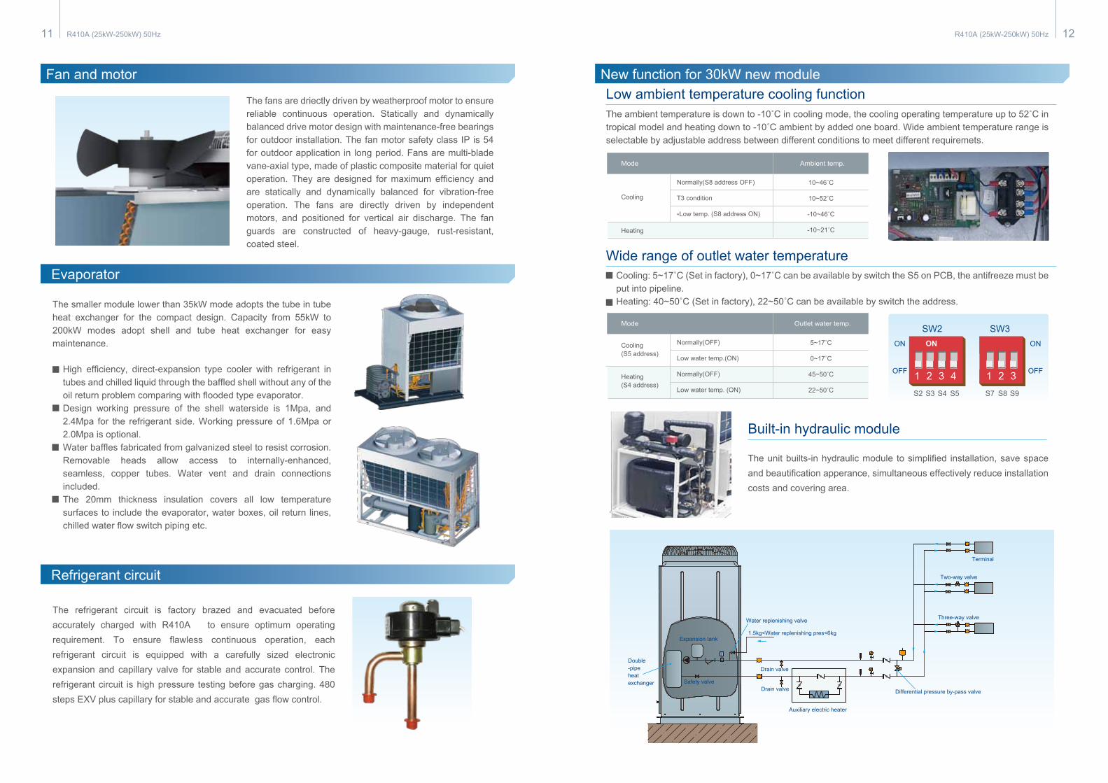
The fans are driectly driven by weatherproof motor to ensure reliable continuous operation. Statically and dynamically balanced drive motor design with maintenance-free bearings for outdoor installation. The fan motor safety class IP is 54 for outdoor application in long period. Fans are multi-blade vane-axial type, made of plastic composite material for quiet operation. They are designed for maximum efficiency and are statically and dynamically balanced for vibration-free operation. The fans are directly driven by independent motors, and positioned for vertical air discharge. The fan guards are constructed of heavy-gauge, rust-resistant, coated steel.
The ambient temperature is down to -10˚C in cooling mode, the cooling operating temperature up to 52˚C in tropical model and heating down to -10˚C ambient by added one board. Wide ambient temperature range is selectable by adjustable address between different conditions to meet different requiremets.
The unit builts-in hydraulic module to simplified installation, save space and beautification apperance, simultaneous effectively reduce installation costs and covering area.
Cooling: 5~17˚C (Set in factory), 0~17˚C can be available by switch the S5 on PCB, the antifreeze must be put into pipeline.Heating: 40~50˚C (Set in factory), 22~50˚C can be available by switch the address.The smaller module lower than 35kW mode adopts the tube in tube
heat exchanger for the compact design. Capacity from 55kW to 200kW modes adopt shell and tube heat exchanger for easy maintenance.
High efficiency, direct-expansion type cooler with refrigerant in tubes and chilled liquid through the baffled shell without any of the oil return problem comparing with flooded type evaporator.Design working pressure of the shell waterside is 1Mpa, and 2.4Mpa for the refrigerant side. Working pressure of 1.6Mpa or 2.0Mpa is optional.Water baffles fabricated from galvanized steel to resist corrosion. Removable heads allow access to internally-enhanced, seamless, copper tubes. Water vent and drain connections included. The 20mm thickness insulation covers all low temperature surfaces to include the evaporator, water boxes, oil return lines, chilled water flow switch piping etc.
The refrigerant circuit is factory brazed and evacuated before accurately charged with R410A to ensure optimum operating requirement. To ensure flawless continuous operation, each refrigerant circuit is equipped with a carefully sized electronic expansion and capillary valve for stable and accurate control. The refrigerant circuit is high pressure testing before gas charging. 480 steps EXV plus capillary for stable and accurate gas flow control.
Fan and motor New function for 30kW new module
Evaporator
Refrigerant circuit
Low ambient temperature cooling function
Wide range of outlet water temperature
Built-in hydraulic module
Mode
Cooling
Heating
Ambient temp.
Normally(S8 address OFF)
T3 condition
*Low temp. (S8 address ON)
10~46˚C
10~52˚C
-10~46˚C
-10~21˚C
Mode
Cooling(S5 address)
Heating(S4 address)
Outlet water temp.
Normally(OFF)
Low water temp.(ON)
Normally(OFF)
Low water temp. (ON)
5~17˚C
0~17˚C
45~50˚C
22~50˚C
ON
OFF
ON
OFF 1 2 3
ON
1 2 3 4
SW2 SW3
S2 S3 S4 S5 S7 S8 S9
Auxiliary electric heater
Terminal
Two-way valve
Drain valve
Drain valve
Water replenishing valve
Expansion tank
Double -pipe heat exchanger Safety valve
1.5kg<Water replenishing pres<6kg
Three-way valve
Differential pressure by-pass valve

14R410A (25kW-250kW) 50HzR410A (25kW-250kW) 50Hz13
Each module has two compressors with two separate units, one double-pipe evaporator for two systems.
Each module has two compressors with two separate units, one shell and tube evaporator for two systems.
25/30kW module refrigeration system sketch drawing
55/60/65kW module refrigeration system sketch drawing
Dry type evaporator
Condenser
Water flow direction Compressor B
Low pressure cylinder B
4-Way valve A
Fan A
EXV
Capillary
EXV
4"
Capillary
Fan B
4-Way valve B
Compressor A
Low pressure cylinder A
Each module has three compressors with two separate units, one shell and tube evaporator for two systems.
65kW digital module refrigeration system sketch drawing (MGB-D65W/RN1)
Compressor A Compressor B
Low pressure cylinder A Low pressure cylinder B
4-way valve A 4-way valve B Condenser
Evaporator(Double-pipe heat exchanger)
Filte
r B
Fan
Filte
r A
throttle parts A
throttle parts B
Dis
char
ge p
ipe
Suc
tion
pipe Water inlet
Water outlet
System sketch drawingCooling: 5~17˚C (Set in factory), 0~17˚C can be available by switch the S5 on PCB, the antifreeze must be put into pipeline.Heating: 40~50˚C (Set in factory), 22~50˚C can be available by switch the address.
The program and hardware standardziation design efficiently manage raw material, the program parameter was written into EEPROM chip to realize modification, customized and resolve problems after sales.The electrical panels are designed orderly and observably that all power wiring have been finished at factory.
New function for 65kW digitatl module and 250kW module
Wide range of outlet water temperature
Humanization remote control
Optimized electrical design
Large capacity,combined freely, provide maximum reliability, high efficiency and quiet operation.
Mode
Cooling(S5 address)
Heating(S4 address)
Outlet water temp.
Normally(OFF)
Low water temp.(ON)
Normally(OFF)
Low water temp. (ON)
5~17˚C
0~17˚C
45~50˚C
22~50˚C
ON
OFF
ON
OFF 1 2 3
ON
1 2 3 4
SW2 SW3
S2 S3 S4 S5 S7 S8 S9
S7 address on PCB should be switched to ON to realize remote control, more simple and convenient control for customer, the function as following: Remote ON/OFF. Remote mode selection for heating and cooling. Remote alarm.
Max 8 modules
250kW 250kW 2000kW
Condenser
Dry type evaporator
Compressor B
Low pressure cylinder B
Fan A
EXV
EXVCapillary
T3A
T3A
Capillary
Fan B
4-Way valve B
4-Way valve A
Low pressure cylinder A
Pressure switch
Pressure switch
Pressure switch
Com.A1digital
Com.A2
Pressure switch
Pressure switch
Pressure switch
Discharge switch
Discharge switch
Water flow direction

16R410A (25kW-200kW) 50Hz15 R410A (25kW-250kW) 50Hz
Specification
Each module has four compressors with two separate units, one shell and tube evaporator for four systems.
Each module has six compressors with three separate units, one shell and tube evaporator for six systems.
Dry type evaporator
Condenser
Compressor B
Low pressure cylinder B
4-Way valve A
Fan A
EXV
Capillary
EXV
2-1/2"
Unit 2
Capillary
Fan B
4-Way valve B
Compressor A
Low pressure cylinder AUnit 1
Dry type evaporator
Condenser
Compressor B
Low pressure cylinder B
4-Way valve A
Fan A
EXV
Capillary
EXV
3"
Unit 2
Unit 3
Capillary
Fan B
4-Way valve B
Compressor A
Low pressure cylinder AUnit 1
130kW module refrigeration system sketch drawing
200kW module refrigeration system sketch drawing
Each module has eight compressors with two separate units, one shell and tube evaporator for four systems.
Dry type evaporator
Condenser
Compressor B1
Compressor B2
Low pressure cylinder B
4-Way valve A
Fan A
EXV
Capillary
EXV
4"
Unit 2
Capillary
Fan B
4-Way valve B
Compressor A1
Compressor A2
Low pressure cylinder AUnit 1
250kW module refrigeration system sketch drawing
Water flow direction
Water flow direction
Water flow direction

18R410A (25kW-250kW) 50HzR410A (25kW-250kW) 50Hz17
Note: Specifications are based on the following conditions: Cool-ing : chilled water inlet/outlet: 12°C / 7°C, and outdoor air temp. of 35°(117°F)CDB. Heating : warm water inlet/outlet: 40°C / 45°C, and outdoor air temp. 7°CDB/6°CWB. Water side fouling factor: 0.086m2·°C/kW.
Note: Specifications are based on the following conditions: Cool-ing : chilled water inlet/outlet: 12°C / 7°C, and outdoor air temp. of 35°(117°F)CDB. Heating : warm water inlet/outlet: 40°C / 45°C, and outdoor air temp. 7°CDB/6°CWB. Water side fouling factor: 0.086m2·°C/kW.
SpecificationkW
kW
V/Ph/Hz
A
A
Pieces
kW
A
kW
A
kW
A
kg
Pieces
103m3/h
A
kW
kPa
mm
m3/h
MPa
mm
mm
kg
kg
mm2
mm2
dB(A)
°C
°C
Cooling Capacity
Heating Capacity
Power supply
Power supply
Compressor
Power input
Max. Input consumption
Max. Current
Refrigerant
Condenser (Air side)
Evaporator (Water side)
Dimension
Weight
Connection
Control type
Safety protection device
Noise level
Operation water temp.
Ambient temp.
28
29.5
380-415/3/50
50
36
Scroll (fixed speed)
Copeland
2
9.3
14.6
9.2
14.3
12.6
21.8
R410A
3.5×2
Fin-coil
1
12
YDK400-8-YA
3.1
0.4
Double-pipe
60
DN40
4.4
1
Flexible joint
1514×1865×841
1590×2065×995
380
400
10×4+10×1
0.75×3-core with shielding
Wired controller
65
Cooling: 5~17 Heating: 45~50
Cooling: 10~46 Heating: -10~21
28
29.5
380-415/3/50
50
36
Digital Scroll + Fixed speed
Copeland
1+1
9.3
14.6
9.2
14.3
12.5
21.5
R410A
3.5×2
Fin-coil
1
12
YDK400-8-YA
3.1
0.4
Double-pipe
60
DN40
4.4
1
Flexible joint
1514×1865×841
1590×2065×995
380
400
10×4+10×1
0.75×3-core with shielding
Wired controller
65
Cooling: 5~17 Heating: 45~50
Cooling: 10~46 Heating: -10~21
30
32
380-415/3/50
50
36
Scroll (fixed speed)
Copeland
2
10.0
16.3
9.8
16.0
12.6
21.8
R410A
3.5×2
Fin-coil
1
12
YDK400-8-YA
3.1
0.4
Double-pipe
60
DN40
5.2
1
Flexible joint
1514×1865×841
1590×2065×995
380
400
10×4+10×1
0.75×3-core with shielding
Wired controller
65
Cooling: 5~17 Heating: 45~50
Cooling: 10~46 Heating: -10~21
30
32
380-415/3/50
50
36
Digital Scroll + Fixed speed
Copeland
1+1
10.0
16.3
9.8
16.0
12.5
21.5
R410A
3.5×2
Fin-coil
1
12
YDK400-8-YA
3.1
0.4
Double-pipe
60
DN40
5.2
1
Flexible joint
1514×1865×841
1590×2065×995
380
400
10×4+10×1
0.75×3-core with shielding
Wired controller
65
Cooling: 5~17 Heating: 45~50
Cooling: 10~46 Heating: -10~21
Manual switch
Fuse
Type
Brand
Quantity
Cooling
Cooling rated current
Heating
Heating rated current
Type
Weight
Air side heat-exchanger type
Quantity of fan motor
Air flow volume
Fan motor model
Fan motor rated current
Fan motor input
Water side heat-exchanger type
Water resistance loss
Water inlet/outlet pipeline inside normal diameter
Water flow volume
Max. Pressure
Water pipe connection type
Net(W×H×D)
Packing size(W×H×D)
Net weight
Operation weight
Power current
Signal wiring
Model MGB-F25W/RN1 MGB-D25W/RN1 MGB-F30W/RN1 MGB-D30W/RN1kW
kW
V/Ph/Hz
A
A
Pieces
kW
A
kW
A
kW
A
kg
Pieces
103m3/h
A
kW
kPa
mm
m3/h
MPa
mm
mm
kg
kg
mm2
mm2
dB(A)
°C
°C
Cooling Capacity
Heating Capacity
Power supply
Power supply
Compressor
Power input
Max. Input consumption
Max. Current
Refrigerant
Condenser (Air side)
Evaporator (Water side)
Dimension
Weight
Connection
Control type
Safety protection device
Noise level
Operation water temp.
Ambient temp.
Manual switch
Fuse
Type
Brand
Quantity
Cooling
Cooling rated current
Heating
Heating rated current
Type
Weight
Air side heat-exchanger type
Quantity of fan motor
Air flow volume
Fan motor model
Fan motor rated current
Fan motor input
Water side heat-exchanger type
Water resistance loss
Water inlet/outlet pipeline inside normal diameter
Water flow volume
Max. Pressure
Water pipe connection type
Net(W×H×D)
Packing size(W×H×D)
Net weight
Operation weight
Power current
Signal wiring
Model
60
64
380-400/3/50
125
100
Scroll (fixed speed)
Danfoss
2
19.3
33.6
19.8
34.3
28.2
47.6
R410A
7.0×2
Fin-coil
2
24
YDK550-6D
4.5×2
0.55×2
Shell-tube
15
DN100
10.3
1
Flexible joint
2000×1880×900
2090×2020×985
580
650
16×4+10×1
0.75×3-core with shielding
Wired controller
67
Cooling: 5~17 Heating: 45~50
Cooling: 10~46 Heating: -10~21
MGB-F60W/RN1
High/low-pressure switch, anti-frost protection, water flow volume controller, over-load protection, and power phases
sequence protection etc.
High/low-pressure switch, anti-frost protection, water flow volume controller, over-load protection, and power phases
sequence protection etc.
High/low-pressure switch, anti-frost protection, water flow volume controller, over-load protection, and power phases
sequence protection etc.
High/low-pressure switch, anti-frost protection, water flow volume controller, over-load protection, and power phases
sequence protection etc.
MGB-F55W/RN1
55
59
380-400/3/50
125
100
Scroll (fixed speed)
Danfoss
2
17.5
30.5
18.3
31.5
28.2
47.6
R410A
7.0×2
Fin-coil
2
24
YDK550-6D
4.5×2
0.55×2
Shell-tube
15
DN100
9.4
1
Flexible joint
2000×1880×900
2090×2020×985
580
650
16×4+10×1
0.75×3-core with shielding
Wired controller
67
Cooling: 5~17 Heating: 45~50
Cooling: 10~46 Heating: -10~21
30
32
380-415/3/50
50
36
Fixed speed
Copeland
1+1
10+1.2(Pump)
18.3
9.8+1.2(Pump)
17.8
13.4
22.5
R410A
3.5×2
Fin-coil
1
12
YDK550-6E
4.5
0.55
Double-pipe
/
DN40
5.2
1
Flexible joint
1514×1865×841
1590×2065×995
430
450
10×4+6×1
0.75×3-core with shielding
Wired controller
67Cooling: 5~17( 0°C must add antifreeze)Heating: 22~50Cooling: -10~46 Heating: -10~21
30
32
380-415/3/50
50
36
Digital Scroll + Fixed speed
Copeland
1+1
10+1.2(Pump)
18.3
9.8+1.2(Pump)
17.8
13.4
22.5
R410A
3.5×2
Fin-coil
1
12
YDK550-6E
4.5
0.55
Double-pipe
/
DN40
5.2
1
Flexible joint
1514×1865×841
1590×2065×995
430
450
10×4+6×1
0.75×3-core with shielding
Wired controller
67Cooling: 5~17( 0°C must add antifreeze)Heating: 22~50Cooling: -10~46 Heating: -10~21
MGCSL-F30W/RN1 MGCSL-D30W/RN1

20R410A (25kW-200kW) 50Hz19 R410A (25kW-250kW) 50Hz
Capacity table
Note: Specifications are based on the following conditions: Cool-ing : chilled water inlet/outlet: 12°C / 7°C, and outdoor air temp. of 35°(117°F)CDB. Heating : warm water inlet/outlet: 40°C / 45°C, and outdoor air temp. 7°CDB/6°CWB. Water side fouling factor: 0.086m2·°C/kW.
kW
kW
V/Ph/Hz
A
A
Pieces
kW
A
kW
A
kW
A
kg
Pieces
103m3/h
A
kW
kPa
mm
m3/h
MPa
mm
mm
kg
kg
mm2
mm2
dB(A)
°C
°C
Cooling Capacity
Heating Capacity
Power supply
Power supply
Compressor
Power input
Max. Input consumption
Max. Current
Refrigerant
Condenser (Air side)
Evaporator (Water side)
Dimension
Weight
Connection
Control type
Safety protection device
Noise level
Operation water temp.
Ambient temp.
Manual switch
Fuse
Type
Brand
Quantity
Cooling
Cooling rated current
Heating
Heating rated current
Type
Weight
Air side heat-exchanger type
Quantity of fan motor
Air flow volume
Fan motor model
Fan motor rated current
Fan motor input
Water side heat-exchanger type
Water resistance loss
Water inlet/outlet pipeline inside normal diameter
Water flow volume
Max. Pressure
Water pipe connection type
Net(W×H×D)
Packing size(W×H×D)
Net weight
Operation weight
Power current
Signal wiring
Model
65
69
380-400/3/50
125
100
Scroll (fixed speed)
Danfoss
2
20.4
36.5
21.5
37.2
28.2
47.6
R410A
7.0×2
Fin-coil
2
24
YDK550-6D
4.5×2
0.55×2
Shell-tube
15
DN100
11.2
1
Flexible joint
2000×1880×900
2090×2020×985
580
650
16×4+10×1
0.75×3-core with shielding
Wired controller
67
Cooling: 5~17 Heating: 45~50
Cooling: 10~46 Heating: -10~21
65
69
380-415/3/50
150
100
Scroll (fixed speed+digital scroll)
Copeland
3
20.4
36.5
21.5
37.2
27.5
46
R410A
7.0×2
Fin-coil
2
24
YDK550-6E
4.5×2
0.55×2
Shell-tube
15
DN100
11.2
1
Flexible joint
2000×1880×900
2090×2020×985
600
670
25×4+16×1
0.75×3-core with shielding
Wired controller
67Cooling: 5~17( 0°C must add antifreeze)Heating: 22~50Cooling: 10~46
Heating: -10~21
130
138
380-400/3/50
250
200
Scroll (fixed speed)
Danfoss
4
40.8
73
43
74.4
55.5
93.8
R410A
7.0×4
Fin-coil
4
48
YDK550-6D
4.5×4
0.55×4
Shell-tube
25
DN65
22.4
1
Flexible joint
2000×2090×1685
2080×2240×1755
1150
1270
35×3+16×2
0.75×3-core with shielding
Wired controller
70
Cooling: 5~17 Heating: 45~50
Cooling: 10~46 Heating: -10~21
185
200
380-400/3/50
400
300
Scroll (fixed speed)
Danfoss
6
63
110
61
107
78.3
133.4
R410A
7.0×6
Fin-coil
6
72
YDK550-6D
4.5×6
0.55×6
Shell-tube
30
DN80
31.8
1
Flexible joint
2850×2110×2000
2980×2260×2135
1730
2000
75×3+35×2
0.75×3-core with shielding
Wired controller
74
Cooling: 5~17 Heating: 45~50
Cooling: 10~46 Heating: -10~21
MGB-F65W/RN1 MGB-D65W/RN1 MGB-F130W/RN1 MGB-F200W/RN1
High/low-pressure switch, anti-frost
protection, water flow volume controller,
over-load protection, and power phases sequence
protection etc.
Low ambient temperature drive-up protection,Low-temperature protection of
shell-and-tube heat exchanger,High/low-pressure
switch, anti-frost protection, water flow volume controller, over-load protection, and power phases
sequence protection etc.
High/low-pressure switch, anti-frost protection, water flow volume controller, over-load protection, and power phases
sequence protection etc.
250
216
380-400/3/50
450
350
Scroll (fixed speed)
Copeland
8
78.3
141.9
80
146
104.9
194.6
R410A
15×4
Fin-coil
8
96
YS700-6F-1/YS700-6F-2
14.4×8
5.6×8
Shell-tube
40
DN100
43
1
Flexible joint
3800×2130×2000
3900×2200×2100
2450
2600
185×4+70×1
0.75×3-core with shielding
Wired controller
74Cooling: 5~17(0°C
must add antifreeze) Heating: 22~50Cooling: 10~52
Heating: -10~21
MGBT-F250W/RN1
22R410A (25kW-250kW) 50Hz21 R410A (25kW-250kW) 50Hz
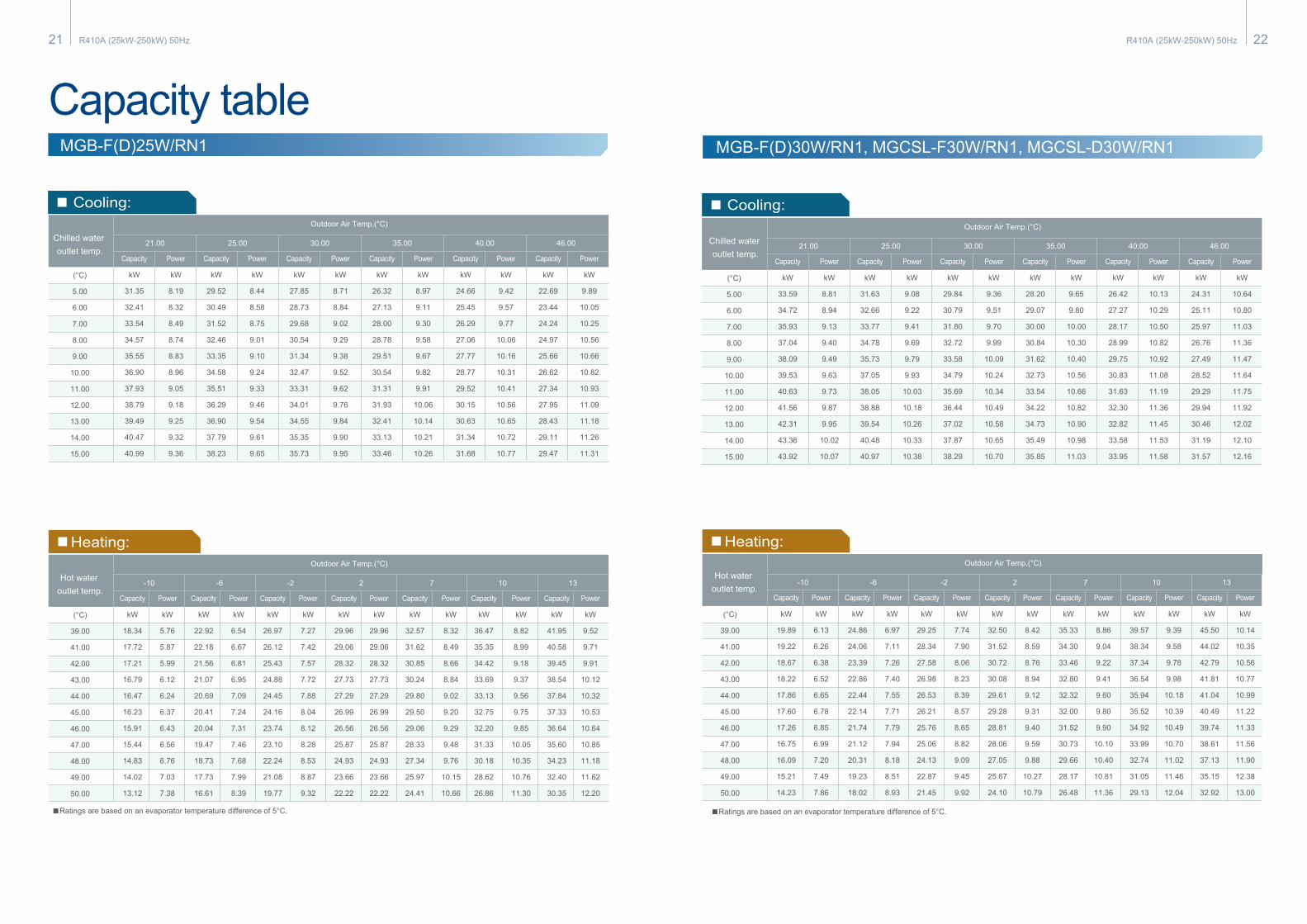
Cooling:
Chilled water outlet temp.
Outdoor Air Temp.(°C)
(°C)
5.00
6.00
7.00
8.00
9.00
10.00
11.00
12.00
13.00
14.00
15.00
Capacity
kW
33.59
34.72
35.93
37.04
38.09
39.53
40.63
41.56
42.31
43.36
43.92
Power
kW
8.81
8.94
9.13
9.40
9.49
9.63
9.73
9.87
9.95
10.02
10.07
Capacity
kW
31.63
32.66
33.77
34.78
35.73
37.05
38.05
38.88
39.54
40.48
40.97
Power
kW
9.08
9.22
9.41
9.69
9.79
9.93
10.03
10.18
10.26
10.33
10.38
Capacity
kW
29.84
30.79
31.80
32.72
33.58
34.79
35.69
36.44
37.02
37.87
38.29
Power
kW
9.36
9.51
9.70
9.99
10.09
10.24
10.34
10.49
10.58
10.65
10.70
Capacity
kW
28.20
29.07
30.00
30.84
31.62
32.73
33.54
34.22
34.73
35.49
35.85
Power
kW
9.65
9.80
10.00
10.30
10.40
10.56
10.66
10.82
10.90
10.98
11.03
Capacity
kW
26.42
27.27
28.17
28.99
29.75
30.83
31.63
32.30
32.82
33.58
33.95
Power
kW
10.13
10.29
10.50
10.82
10.92
11.08
11.19
11.36
11.45
11.53
11.58
Capacity
kW
24.31
25.11
25.97
26.76
27.49
28.52
29.29
29.94
30.46
31.19
31.57
Power
kW
10.64
10.80
11.03
11.36
11.47
11.64
11.75
11.92
12.02
12.10
12.16
21.00 25.00 30.00 35.00 40.00 46.00
Outdoor Air Temp.(°C)
Capacity
kW
19.89
19.22
18.67
18.22
17.86
17.60
17.26
16.75
16.09
15.21
14.23
Power
kW
6.13
6.26
6.38
6.52
6.65
6.78
6.85
6.99
7.20
7.49
7.86
Capacity
kW
24.86
24.06
23.39
22.86
22.44
22.14
21.74
21.12
20.31
19.23
18.02
Power
kW
6.97
7.11
7.26
7.40
7.55
7.71
7.79
7.94
8.18
8.51
8.93
Capacity
kW
29.25
28.34
27.58
26.98
26.53
26.21
25.76
25.06
24.13
22.87
21.45
Power
kW
7.74
7.90
8.06
8.23
8.39
8.57
8.65
8.82
9.09
9.45
9.92
Capacity
kW
32.50
31.52
30.72
30.08
29.61
29.28
28.81
28.06
27.05
25.67
24.10
Power
kW
8.42
8.59
8.76
8.94
9.12
9.31
9.40
9.59
9.88
10.27
10.79
Capacity
kW
35.33
34.30
33.46
32.80
32.32
32.00
31.52
30.73
29.66
28.17
26.48
Power
kW
8.86
9.04
9.22
9.41
9.60
9.80
9.90
10.10
10.40
10.81
11.36
Capacity
kW
39.57
38.34
37.34
36.54
35.94
35.52
34.92
33.99
32.74
31.05
29.13
Power
kW
9.39
9.58
9.78
9.98
10.18
10.39
10.49
10.70
11.02
11.46
12.04
Capacity
kW
45.50
44.02
42.79
41.81
41.04
40.49
39.74
38.61
37.13
35.15
32.92
Power
kW
10.14
10.35
10.56
10.77
10.99
11.22
11.33
11.56
11.90
12.38
13.00
Heating:
(°C)
39.00
41.00
42.00
43.00
44.00
45.00
46.00
47.00
48.00
49.00
50.00
Hot water outlet temp.
-10 -6 -2 2 7 10 13
MGB-F(D)30W/RN1, MGCSL-F30W/RN1, MGCSL-D30W/RN1
Ratings are based on an evaporator temperature difference of 5°C.
Capacity tableMGB-F(D)25W/RN1
Cooling:
Chilled water outlet temp.
Outdoor Air Temp.(°C)
(°C)
5.00
6.00
7.00
8.00
9.00
10.00
11.00
12.00
13.00
14.00
15.00
Capacity
kW
31.35
32.41
33.54
34.57
35.55
36.90
37.93
38.79
39.49
40.47
40.99
Power
kW
8.19
8.32
8.49
8.74
8.83
8.96
9.05
9.18
9.25
9.32
9.36
Capacity
kW
29.52
30.49
31.52
32.46
33.35
34.58
35.51
36.29
36.90
37.79
38.23
Power
kW
8.44
8.58
8.75
9.01
9.10
9.24
9.33
9.46
9.54
9.61
9.65
Capacity
kW
27.85
28.73
29.68
30.54
31.34
32.47
33.31
34.01
34.55
35.35
35.73
Power
kW
8.71
8.84
9.02
9.29
9.38
9.52
9.62
9.76
9.84
9.90
9.95
Capacity
kW
26.32
27.13
28.00
28.78
29.51
30.54
31.31
31.93
32.41
33.13
33.46
Power
kW
8.97
9.11
9.30
9.58
9.67
9.82
9.91
10.06
10.14
10.21
10.26
Capacity
kW
24.66
25.45
26.29
27.06
27.77
28.77
29.52
30.15
30.63
31.34
31.68
Power
kW
9.42
9.57
9.77
10.06
10.16
10.31
10.41
10.56
10.65
10.72
10.77
Capacity
kW
22.69
23.44
24.24
24.97
25.66
26.62
27.34
27.95
28.43
29.11
29.47
Power
kW
9.89
10.05
10.25
10.56
10.66
10.82
10.93
11.09
11.18
11.26
11.31
21.00 25.00 30.00 35.00 40.00 46.00
Outdoor Air Temp.(°C)
Capacity
kW
18.34
17.72
17.21
16.79
16.47
16.23
15.91
15.44
14.83
14.02
13.12
Power
kW
5.76
5.87
5.99
6.12
6.24
6.37
6.43
6.56
6.76
7.03
7.38
Capacity
kW
22.92
22.18
21.56
21.07
20.69
20.41
20.04
19.47
18.73
17.73
16.61
Power
kW
6.54
6.67
6.81
6.95
7.09
7.24
7.31
7.46
7.68
7.99
8.39
Capacity
kW
26.97
26.12
25.43
24.88
24.45
24.16
23.74
23.10
22.24
21.08
19.77
Power
kW
7.27
7.42
7.57
7.72
7.88
8.04
8.12
8.28
8.53
8.87
9.32
Capacity
kW
29.96
29.06
28.32
27.73
27.29
26.99
26.56
25.87
24.93
23.66
22.22
Power
kW
29.96
29.06
28.32
27.73
27.29
26.99
26.56
25.87
24.93
23.66
22.22
Capacity
kW
32.57
31.62
30.85
30.24
29.80
29.50
29.06
28.33
27.34
25.97
24.41
Power
kW
8.32
8.49
8.66
8.84
9.02
9.20
9.29
9.48
9.76
10.15
10.66
Capacity
kW
36.47
35.35
34.42
33.69
33.13
32.75
32.20
31.33
30.18
28.62
26.86
Power
kW
8.82
8.99
9.18
9.37
9.56
9.75
9.85
10.05
10.35
10.76
11.30
Capacity
kW
41.95
40.58
39.45
38.54
37.84
37.33
36.64
35.60
34.23
32.40
30.35
Power
kW
9.52
9.71
9.91
10.12
10.32
10.53
10.64
10.85
11.18
11.62
12.20
Heating:
(°C)
39.00
41.00
42.00
43.00
44.00
45.00
46.00
47.00
48.00
49.00
50.00
Hot water outlet temp.
-10 -6 -2 2 7 10 13
Ratings are based on an evaporator temperature difference of 5°C.

24R410A (25kW-250kW) 50Hz23 R410A (25kW-250kW) 50Hz
Cooling:
Chilled water outlet temp.
Outdoor Air Temp.(°C)
(°C)
5.00
6.00
7.00
8.00
9.00
10.00
11.00
12.00
13.00
14.00
15.00
Capacity
kW
67.17
69.44
71.87
74.09
76.18
79.06
81.27
83.13
84.61
86.72
87.83
Power
kW
17.00
17.26
17.61
18.14
18.32
18.59
18.78
19.05
19.20
19.34
19.43
Capacity
kW
63.25
65.33
67.54
69.57
71.46
74.10
76.09
77.76
79.08
80.97
81.93
Power
kW
17.52
17.80
18.16
18.70
18.89
19.17
19.36
19.64
19.80
19.94
20.03
Capacity
kW
59.67
61.57
63.60
65.44
67.16
69.58
71.38
72.88
74.04
75.74
76.57
Power
kW
18.07
18.35
18.72
19.28
19.47
19.76
19.96
20.25
20.41
20.55
20.65
Capacity
kW
56.40
58.14
60.00
61.68
63.24
65.45
67.09
68.43
69.46
70.99
71.70
Power
kW
18.62
18.91
19.30
19.88
20.07
20.37
20.57
20.87
21.04
21.19
21.29
Capacity
kW
52.85
54.54
56.34
57.98
59.51
61.66
63.27
64.60
65.64
67.15
67.90
Power
kW
19.56
19.86
20.27
20.87
21.08
21.39
21.60
21.92
22.09
22.25
22.36
Capacity
kW
48.62
50.23
51.95
53.51
54.99
57.03
58.58
59.88
60.91
62.38
63.14
Power
kW
20.53
20.85
21.28
21.92
22.13
22.46
22.68
23.01
23.20
23.36
23.47
21.00 25.00 30.00 35.00 40.00 46.00
Outdoor Air Temp.(°C)
Capacity
kW
39.78
38.44
37.33
36.43
35.73
35.21
34.52
33.50
32.18
30.43
28.47
Power
kW
12.39
12.64
12.90
13.16
13.43
13.71
13.84
14.12
14.54
15.12
15.88
Capacity
kW
49.73
48.11
46.78
45.71
44.88
44.29
43.48
42.24
40.63
38.46
36.03
Power
kW
14.08
14.37
14.66
14.96
15.26
15.57
15.73
16.05
16.53
17.19
18.05
Capacity
kW
58.50
56.67
55.17
53.97
53.05
52.41
51.51
50.11
48.25
45.74
42.90
Power
kW
15.64
15.96
16.29
16.62
16.96
17.31
17.48
17.83
18.36
19.10
20.05
Capacity
kW
65.00
63.04
61.43
60.16
59.21
58.56
57.62
56.12
54.09
51.33
48.20
Power
kW
17.00
17.35
17.70
18.07
18.43
18.81
19.00
19.38
19.96
20.76
21.80
Capacity
kW
70.65
68.59
66.92
65.61
64.64
64.00
63.04
61.46
59.31
56.35
52.97
Power
kW
17.90
18.26
18.64
19.02
19.40
19.80
20.00
20.40
21.01
21.85
22.94
Capacity
kW
79.13
76.69
74.68
73.09
71.88
71.04
69.85
67.98
65.48
62.09
58.26
Power
kW
18.97
19.36
19.75
20.16
20.57
20.99
21.20
21.62
22.27
23.16
24.32
Capacity
kW
91.00
88.04
85.59
83.61
82.09
80.99
79.49
77.22
74.26
70.29
65.84
Power
kW
20.49
20.91
21.33
21.77
22.21
22.67
22.89
23.35
24.05
25.01
26.26
Heating:
(°C)
39.00
41.00
42.00
43.00
44.00
45.00
46.00
47.00
48.00
49.00
50.00
Hot water outlet temp.
-10 -6 -2 2 7 10 13
MGB-F60W/RN1
Ratings are based on an evaporator temperature difference of 5°C.
Cooling:
Chilled water outlet temp.
Outdoor Air Temp.(°C)
(°C)
5.00
6.00
7.00
8.00
9.00
10.00
11.00
12.00
13.00
14.00
15.00
Capacity
kW
61.58
63.65
65.88
67.91
69.83
72.48
74.50
76.20
77.56
79.49
80.51
Power
kW
15.41
15.65
15.97
16.45
16.61
16.86
17.03
17.28
17.41
17.53
17.62
Capacity
kW
57.98
59.88
61.91
63.77
65.50
67.92
69.75
71.28
72.49
74.22
75.10
Power
kW
15.89
16.14
16.47
16.96
17.12
17.38
17.55
17.81
17.95
18.08
18.17
Capacity
kW
54.70
56.44
58.30
59.99
61.56
63.78
65.43
66.81
67.87
69.43
70.19
Power
kW
16.38
16.64
16.98
17.48
17.65
17.92
18.10
18.36
18.51
18.64
18.73
Capacity
kW
51.70
53.30
55.00
56.54
57.97
60.00
61.50
62.73
63.67
65.07
65.72
Power
kW
16.89
17.15
17.50
18.03
18.20
18.47
18.66
18.93
19.08
19.21
19.31
Capacity
kW
48.44
49.99
51.65
53.15
54.55
56.52
57.99
59.22
60.17
61.56
62.24
Power
kW
17.73
18.01
18.38
18.93
19.11
19.40
19.59
19.87
20.03
20.17
20.27
Capacity
kW
44.57
46.04
47.62
49.06
50.40
52.28
53.70
54.89
55.84
57.19
57.88
Power
kW
18.62
18.91
19.29
19.87
20.07
20.37
20.57
20.87
21.04
21.18
21.29
21.00 25.00 30.00 35.00 40.00 46.00
Outdoor Air Temp.(°C)
Capacity
kW
40.40
35.44
34.42
33.58
32.94
32.46
31.82
30.88
29.66
28.05
26.24
Power
kW
11.45
11.68
11.92
12.17
12.41
12.67
12.79
13.05
13.44
13.98
14.68
Capacity
kW
45.84
44.36
43.13
42.14
41.38
40.83
40.08
38.94
37.45
35.46
33.22
Power
kW
13.01
13.28
13.55
13.82
14.11
14.39
14.54
14.83
15.27
15.89
16.68
Capacity
kW
53.93
52.24
50.86
49.75
48.91
48.32
47.49
46.20
44.48
42.16
39.55
Power
kW
14.46
14.75
15.05
15.36
15.67
15.99
16.15
16.48
16.97
17.65
18.53
Capacity
kW
59.92
58.11
56.63
55.46
54.58
53.99
53.12
51.73
49.87
47.32
44.43
Power
kW
15.71
16.04
16.36
16.70
17.04
17.39
17.56
17.91
18.45
19.19
20.14
Capacity
kW
65.13
63.24
61.69
60.48
59.59
59.00
58.12
56.66
54.68
51.95
48.83
Power
kW
16.54
16.88
17.22
17.58
17.93
18.30
18.48
18.85
19.42
20.19
21.20
Capacity
kW
72.95
70.70
68.85
67.38
66.26
65.49
64.39
62.67
60.37
57.24
53.71
Power
kW
17.53
17.89
18.26
18.63
19.01
19.40
19.59
19.98
20.58
21.41
22.48
Capacity
kW
83.89
81.16
78.90
77.08
75.67
74.66
73.28
71.19
68.45
64.80
60.69
Power
kW
18.94
19.32
19.72
20.12
20.53
20.95
21.16
21.58
22.23
23.12
24.28
Heating:
(°C)
39.00
41.00
42.00
43.00
44.00
45.00
46.00
47.00
48.00
49.00
50.00
Hot water outlet temp.
-10 -6 -2 2 7 10 13
MGB-F55W/RN1
Ratings are based on an evaporator temperature difference of 5°C.

26R410A (25kW-250kW) 50Hz25 R410A (25kW-250kW) 50Hz
Cooling:
Chilled water outlet temp.
Outdoor Air Temp.(°C)
(°C)
5.00
6.00
7.00
8.00
9.00
10.00
11.00
12.00
13.00
14.00
15.00
Capacity
kW
145.54
150.46
155.71
160.52
165.05
171.31
176.08
180.11
183.33
187.89
190.30
Power
kW
35.93
36.49
37.24
38.35
38.73
39.31
39.69
40.28
40.60
40.88
41.08
Capacity
kW
137.04
141.54
146.34
150.72
154.83
160.55
164.87
168.49
171.33
175.43
177.52
Power
kW
37.05
37.62
38.39
39.54
39.92
40.52
40.92
41.52
41.85
42.14
42.35
Capacity
kW
129.29
133.40
137.80
141.79
145.52
150.75
154.66
157.91
160.42
164.11
165.90
Power
kW
38.19
38.78
39.58
40.76
41.16
41.78
42.19
42.81
43.15
43.45
43.66
Capacity
kW
122.20
125.97
130.00
133.64
137.02
141.82
145.36
148.27
150.49
153.80
155.34
Power
kW
39.37
39.98
40.80
42.02
42.43
43.07
43.49
44.13
44.48
44.79
45.01
Capacity
kW
114.50
118.16
122.07
125.62
128.94
133.59
137.08
139.97
142.22
145.50
147.11
Power
kW
41.34
41.98
42.84
44.13
44.55
45.22
45.67
46.34
46.71
47.03
47.26
Capacity
kW
105.34
108.83
112.55
115.95
119.14
123.57
126.93
129.75
131.98
135.17
136.81
Power
kW
43.41
44.08
44.98
46.33
46.78
47.48
47.95
48.65
49.04
49.38
49.63
21.00 25.00 30.00 35.00 40.00 46.00
Outdoor Air Temp.(°C)
Capacity
kW
85.78
82.89
80.50
78.55
77.03
75.92
74.43
72.23
69.38
65.61
61.38
Power
kW
26.91
27.45
28.01
28.59
29.17
29.76
30.06
30.66
31.58
32.85
34.49
Capacity
kW
107.22
103.75
100.87
98.56
96.78
95.49
93.74
91.09
87.60
82.94
77.70
Power
kW
30.57
31.20
31.83
32.48
33.15
33.82
34.16
34.85
35.89
37.33
39.19
Capacity
kW
126.14
122.20
118.96
116.37
114.39
113.01
111.07
108.05
104.04
98.62
92.50
Power
kW
33.97
34.66
35.37
36.09
36.83
37.58
37.96
38.72
39.88
41.47
43.55
Capacity
kW
140.16
135.93
132.47
129.73
127.67
126.27
124.24
121.00
116.64
110.69
103.93
Power
kW
36.93
37.68
38.45
39.23
40.03
40.85
41.26
42.08
43.35
45.08
47.33
Capacity
kW
152.34
147.91
144.30
141.47
139.38
138.00
135.93
132.53
127.89
121.50
114.21
Power
kW
38.87
39.66
40.47
41.30
42.14
43.00
43.43
44.30
45.63
47.45
49.83
Capacity
kW
170.63
165.36
161.04
157.60
154.99
153.18
150.61
146.58
141.19
133.89
125.63
Power
kW
38.33
39.11
39.91
40.72
41.55
45.58
46.04
46.96
48.37
50.30
52.81
Capacity
kW
196.22
189.83
184.55
180.29
177.00
174.63
171.39
166.52
160.11
151.56
141.96
Power
kW
41.39
42.24
43.10
43.98
44.88
49.23
49.72
50.71
52.23
54.32
57.04
Heating:
(°C)
39.00
41.00
42.00
43.00
44.00
45.00
46.00
47.00
48.00
49.00
50.00
Hot water outlet temp.
-10 -6 -2 2 7 10 13
MGB-F130W/RN1
Cooling:
Chilled water outlet temp.
Outdoor Air Temp.(°C)
(°C)
5.00
6.00
7.00
8.00
9.00
10.00
11.00
12.00
13.00
14.00
15.00
Capacity
kW
72.77
75.23
77.85
80.26
82.52
85.65
88.04
90.06
91.66
93.94
95.15
Power
kW
17.97
18.25
18.62
19.18
19.36
19.65
19.85
20.14
20.30
20.44
20.54
Capacity
kW
68.52
70.77
73.17
75.36
77.41
80.27
82.44
84.24
85.67
87.72
88.76
Power
kW
18.52
18.81
19.19
19.77
19.96
20.26
20.46
20.76
20.93
21.07
21.18
Capacity
kW
64.64
66.70
68.90
70.90
72.76
75.38
77.33
78.95
80.21
82.05
82.95
Power
kW
19.10
19.39
19.79
20.38
20.58
20.89
21.09
21.40
21.57
21.72
21.83
Capacity
kW
61.10
62.99
65.00
66.82
68.51
70.91
72.68
74.13
75.25
76.90
77.67
Power
kW
19.69
19.99
20.40
21.01
21.22
21.53
21.75
22.06
22.24
22.40
22.51
Capacity
kW
57.25
59.08
61.04
62.81
64.47
66.80
68.54
69.98
71.11
72.75
73.55
Power
kW
20.67
20.99
21.42
22.06
22.28
22.61
22.83
23.17
23.35
23.52
23.63
Capacity
kW
52.67
54.41
56.27
57.97
59.57
61.79
63.47
64.87
65.99
67.58
68.41
Power
kW
21.70
22.04
22.49
23.17
23.39
23.74
23.98
24.33
24.52
24.69
24.81
21.00 25.00 30.00 35.00 40.00 46.00
Outdoor Air Temp.(°C)
Capacity
kW
42.89
41.45
40.25
39.28
38.52
37.96
37.22
36.12
34.69
32.80
30.69
Power
kW
13.45
13.73
14.01
14.29
14.58
14.88
15.03
15.33
15.79
16.42
17.24
Capacity
kW
53.61
51.87
50.44
49.28
48.39
47.75
46.87
45.54
43.80
41.47
38.85
Power
kW
15.29
15.60
15.92
16.24
16.57
16.91
17.08
17.42
17.95
18.66
19.60
Capacity
kW
63.07
61.10
59.48
58.18
57.20
56.51
55.54
54.03
52.02
49.31
46.25
Power
kW
16.99
17.33
17.69
18.05
18.42
18.79
18.98
19.36
19.94
20.74
21.77
Capacity
kW
70.08
67.96
66.23
64.86
63.84
63.14
62.12
60.50
58.32
55.34
51.96
Power
kW
18.46
18.84
19.22
19.62
20.02
20.43
20.63
21.04
21.67
22.54
23.67
Capacity
kW
76.17
73.95
72.15
70.74
69.69
69.00
67.97
66.27
63.95
60.75
57.10
Power
kW
19.43
19.83
20.24
20.65
21.07
21.50
21.72
22.15
22.81
23.73
24.91
Capacity
kW
85.31
82.68
80.52
78.80
77.50
76.59
75.31
73.29
70.60
66.95
62.81
Power
kW
20.60
21.02
21.45
21.89
22.33
22.79
23.02
23.48
24.18
25.15
26.41
Capacity
kW
98.11
94.92
92.28
90.15
88.50
87.31
85.70
83.26
80.06
75.78
70.98
Power
kW
22.25
22.70
23.17
23.64
24.12
24.61
24.86
25.36
26.12
27.16
28.52
Heating:
(°C)
39.00
41.00
42.00
43.00
44.00
45.00
46.00
47.00
48.00
49.00
50.00
Hot water outlet temp.
-10 -6 -2 2 7 10 13
MGB-F(D)65W/RN1
Ratings are based on an evaporator temperature difference of 5°C. Ratings are based on an evaporator temperature difference of 5°C.

28R410A (25kW-250kW) 50Hz27 R410A (25kW-250kW) 50Hz
Cooling:
Chilled water outlet temp.
Outdoor Air Temp.(°C)
(°C)
5.00
6.00
7.00
8.00
9.00
10.00
11.00
12.00
13.00
14.00
15.00
Capacity
kW
207.12
214.11
221.59
228.44
234.87
237.19
243.81
249.38
253.84
260.15
263.49
Power
kW
55.49
56.35
57.50
59.22
59.80
60.70
61.29
62.19
62.69
63.12
63.43
Capacity
kW
195.03
201.42
208.26
214.49
220.33
222.30
228.28
233.29
237.23
242.91
245.79
Power
kW
57.20
58.09
59.28
61.06
61.65
62.57
63.19
64.11
64.63
65.08
65.40
Capacity
kW
183.99
189.84
196.10
201.78
207.08
208.73
214.15
218.64
222.13
227.23
229.71
Power
kW
58.97
59.89
61.11
62.94
63.55
64.51
65.14
66.10
66.63
67.09
67.42
Capacity
kW
173.90
179.27
185.00
190.18
194.99
196.36
201.27
205.29
208.37
212.96
215.09
Power
kW
60.80
61.74
63.00
64.89
65.52
66.50
67.16
68.14
68.69
69.16
69.50
Capacity
kW
162.94
168.15
173.72
178.77
183.49
184.97
189.80
193.80
196.91
201.46
203.69
Power
kW
63.83
64.83
66.15
68.13
68.80
69.83
70.52
71.55
72.12
72.62
72.98
Capacity
kW
149.91
154.87
160.17
165.00
169.54
171.10
175.75
179.65
182.74
187.15
189.43
Power
kW
67.03
68.07
69.46
71.54
72.24
73.32
74.04
75.13
75.73
76.25
76.63
21.00 25.00 30.00 35.00 40.00 46.00
Outdoor Air Temp.(°C)
Capacity
kW
124.31
120.14
116.66
113.85
111.64
110.03
107.87
104.69
100.55
95.08
88.96
Power
kW
38.17
38.95
39.74
40.55
41.38
42.22
42.65
43.50
44.80
46.60
48.93
Capacity
kW
155.39
150.36
146.19
142.84
140.26
138.40
135.86
132.01
126.96
120.20
112.61
Power
kW
43.37
44.26
45.16
46.08
47.02
47.98
48.46
49.43
50.91
52.95
55.60
Capacity
kW
182.81
177.10
172.40
168.65
165.79
163.79
160.97
156.60
150.78
142.93
134.05
Power
kW
48.19
49.18
50.18
51.20
52.25
53.31
53.85
54.92
56.57
58.83
61.78
Capacity
kW
203.13
197.00
191.98
188.01
185.03
183.00
180.06
175.36
169.04
160.41
150.62
Power
kW
52.38
53.45
54.54
55.66
56.79
57.95
58.53
59.70
61.49
63.95
67.15
Capacity
kW
220.79
214.36
209.13
205.03
202.00
200.00
197.00
192.08
185.35
176.08
165.52
Power
kW
55.14
56.26
57.41
58.58
59.78
61.00
61.61
61.81
63.67
66.21
69.52
Capacity
kW
247.28
239.65
233.39
228.40
224.62
222.00
218.28
212.43
204.63
194.05
182.07
Power
kW
58.45
59.64
60.86
62.10
63.37
64.66
65.31
66.61
68.61
71.36
74.92
Capacity
kW
284.38
275.12
267.46
261.29
256.52
253.08
248.40
241.33
232.05
219.66
205.74
Power
kW
63.12
64.41
65.73
67.07
68.44
69.83
70.53
71.94
74.10
77.06
80.92
Heating:
(°C)
39.00
41.00
42.00
43.00
44.00
45.00
46.00
47.00
48.00
49.00
50.00
Hot water outlet temp.
-10 -6 -2 2 7 10 13
MGB-F200W/RN1
Ratings are based on an evaporator temperature difference of 5°C.
MGBT-F250W/RN1
Cooling:
Chilled water outlet temp.
Outdoor Air Temp.(°C)
(°C)
5.00
6.00
7.00
8.00
9.00
10.00
11.00
12.00
13.00
14.00
15.00
Capacity
kW
279.89
289.34
299.44
308.70
317.40
329.43
338.62
346.37
352.55
361.32
365.96
Power
kW
68.96
70.03
71.46
73.61
74.32
75.44
76.18
77.29
77.91
78.45
78.84
Capacity
kW
263.55
272.19
281.43
289.86
297.75
308.75
317.06
324.01
329.49
337.37
341.38
Power
kW
71.09
72.20
73.67
75.88
76.62
77.77
78.53
79.68
80.32
80.88
81.28
Capacity
kW
248.63
256.54
265.00
272.68
279.84
289.90
297.43
303.66
308.51
315.59
319.05
Power
kW
73.29
74.43
75.95
78.23
78.99
80.17
80.96
82.15
82.81
83.38
83.79
Capacity
kW
235.00
242.25
250.00
257.00
263.50
272.72
279.54
285.13
289.41
295.78
298.73
Power
kW
75.56
76.73
78.30
80.65
81.43
82.65
83.47
84.69
85.37
85.96
86.38
Capacity
kW
220.20
227.23
234.75
241.58
247.95
256.90
263.61
269.16
273.49
279.80
282.90
Power
kW
79.34
80.57
82.22
84.68
85.50
86.79
87.64
88.92
89.64
90.26
90.70
Capacity
kW
202.58
209.28
216.44
222.98
229.11
237.64
244.10
249.52
253.80
259.94
263.10
Power
kW
83.30
84.60
86.33
88.92
89.78
91.13
92.02
93.37
94.12
94.77
95.24
Capacity
kW
182.32
188.56
195.23
201.35
207.11
215.06
221.15
226.31
230.45
236.28
239.42
Power
kW
87.47
88.83
90.64
93.36
94.27
95.68
96.62
98.04
98.82
99.51
100.00
21.00 25.00 30.00 35.00 40.00 46.00 52.00
Outdoor Air Temp.(°C)
Capacity
kW
167.82
162.18
157.50
153.69
150.72
148.54
145.63
141.33
135.75
128.36
120.09
Power
kW
50.06
51.08
52.12
53.18
54.27
55.38
55.93
57.05
58.76
61.11
64.17
Capacity
kW
209.78
202.98
197.36
192.84
189.35
186.84
183.41
178.22
171.40
162.27
152.02
Power
kW
56.88
58.04
59.23
60.44
61.67
62.93
63.56
64.83
66.77
69.44
72.92
Capacity
kW
246.80
239.08
232.74
227.67
223.81
221.11
217.31
211.41
203.56
192.95
180.97
Power
kW
63.20
64.49
65.81
67.15
68.52
69.92
70.62
72.03
74.19
77.16
81.02
Capacity
kW
274.22
265.94
259.18
253.82
249.79
247.05
243.08
236.74
228.21
216.56
203.34
Power
kW
68.70
70.10
71.53
72.99
74.48
76.00
76.76
78.30
80.64
83.87
88.06
Capacity
kW
298.07
289.38
282.33
276.79
272.70
270.00
265.95
259.30
250.23
237.71
223.45
Power
kW
72.31
73.79
75.30
76.83
78.40
80.00
80.80
82.42
84.89
88.28
92.70
Capacity
kW
333.83
323.53
315.08
308.34
303.24
299.70
294.67
286.79
276.25
261.96
245.80
Power
kW
76.65
78.22
79.81
81.44
83.10
84.80
85.65
87.36
89.98
93.58
98.26
Capacity
kW
383.91
371.41
361.08
352.75
346.30
341.66
335.34
325.79
313.27
296.54
277.75
Power
kW
82.78
84.47
86.20
87.96
89.75
91.58
92.50
94.35
97.18
101.07
106.12
Heating:
(°C)
39.00
41.00
42.00
43.00
44.00
45.00
46.00
47.00
48.00
49.00
50.00
Hot water outlet temp.
-10 -6 -2 2 7 10 13
Ratings are based on an evaporator temperature difference of 5°C.

30R410A (25kW-250kW) 50Hz29 R410A (25kW-250kW) 50Hz
DimensionApplication range
Unit
mm
inch
Model
MGB-F(D)25W/RN1 MGB-F(D)30W/RN1
A
1514
59.6
B
841
33.11
C
1865
73.43
D
115
4.53
E
315
12.4
F
172
6.77
G
1470
57.87
H
852
33.54
25/30kW moduleOperation temperature range
Water pressure drop
D
E
F
C
B H
A G
Front view Side view
COOLING RANGE
COOLING RANGE
Outdoor air temperature range
-15°C -10°C -5°C 0°C 5°C 10°C 15°C 20°C 25°C 30°C 35°C 40°C 45°C 50°C
10°C 46°C
46°C
HEATING RANGE-10°C
-10°C
21°C
Water outlet temperature range
-15°C -10°C -5°C 0°C 5°C 10°C 15°C 20°C 25°C 30°C 35°C 40°C 45°C 50°C
50°C22°CCOOLING HEATING
50°C45°CHEATING
0°C 17°C
COOLING5°C 17°C
Mounting fixing bolt
Mounting hole 15mm×4
Top view Anchor hole
Model
Cooling
Heating
Outdoor air temperature range
10°C~46°C
-10°C~46°C
-10°C~21°C
-10°C~21°C
Water outlet temperature range
5°C~17°C (7°C is default)
5°C~17°C (7°C is default,0°C must add antifreeze)
5°C~17°C (7°C is default)
45°C ~ 50°C (45°C is default)
22°C ~ 50°C (45°C is default)
Application for module
All modules except MGCSL-F(D)30W/RN1, MGB-D65W/RN1, MGBT-F250W/RN1
Only for MGCSL-F(D)30W/RN1, MGB-D65W/RN1, MGBT-F250W/RN1
Only for MGCSL-F30W/RN1, MGCSL-D30W/RN1
All modules except MGCSL-F(D)30W/RN1, MGB-D65W/RN1, MGBT-F250W/RN1
Only for MGCSL-F(D)30W/RN1, MGB-D65W/RN1, MGBT-F250W/RN1
3.120102030405060708090
3.62 4.13 4.66 5.16 5.68 6.17
25kW/30kw module pressure drop
Water flow(m3/h)
Pre
ssur
e dr
op(K
Pa)
0
5
10
20
25
3055kW/60kW/65kW module pressure drop
1.081 2.072 3.101 4.132 5.18 6.201 7.233 8.26 9.272 10.321 11.343 12.382 13.431 14.411 15.49
130kW module pressure drop
05
10152025303540
5045
2.05 4.13 6.22 8.25 10.34 12.42 14.46 16.53 18.56 20.66 22.72 24.81 26.87 28.93 30.99
250kW module pressure drop
05
1015202530354045
4.312 8.612 12.892 17.231 21.511 25.816 30.115 34.373 38.806 42.959 47.223 51.532
200kW module pressure drop
0
10
20
30
40
50
70
60
3.096 9.288 15.48 21.672 27.864 34.056 40.248Water flow(m3/h) Water flow(m3/h)
Water flow(m3/h)
Pre
ssur
e dr
op(K
Pa)
Pre
ssur
e dr
op(K
Pa)
Pre
ssur
e dr
op(K
Pa)
Pre
ssur
e dr
op(K
Pa)

32R410A (25kW-250kW) 50Hz31 R410A (25kW-250kW) 50Hz
Unit
mm
inch
A
2000
78.74
B
900
35.4
C
1880
74
D
350
13.78
E
1420
55.91
F
225
8.86
G
1500
59.06
H
506
19.92
I
530
20.87
J
930
36.61
K
450
17.72
L
805
31.69
Model
MGB-F55W/RN1MGB-F60W/RN1MGB-F65W/RN1MGB-D65W/RN1
Front view
Top view
55/60/65kW module
I J
K
B
CED
H
A
G
G
L
F
Side view
Anchor hole
B
Mounting fixing bolt
Mounting hole 15mm×4
Unit
mm
inch
Model
MGCSL-F30W/RN1MGCSL-D30W/RN1
A
1514
59.6
B
841
33.11
C
1865
73.43
D
317
12.48
E
874
34.41
F
100
3.94
G
200
7.87
H
1470
57.87
I
852
33.54
30kW new module
D
E
F G
C
B I
A H
Mounting fixing bolt
Mounting hole 15mm×4
Top view Anchor hole
Front view Side view

34R410A (25kW-250kW) 50Hz33 R410A (25kW-250kW) 50Hz
Unit
mm
inch
Model
MGB-F130W/RN1
A
2000
78.74
B
1685
66.34
C
2080
81.89
D
350
13.78
E
1420
55.91
F
506
19.92
G
1550
61.02
H
1586
62.44
Unit
mm
inch
Model
MGB-F200W/RN1
A
2850
112.2
B
2000
78.74
C
2110
83.07
D
3470
136.61
E
2156
84.88
F
506
19.92
G
1888
74.33
H
2388
94.02
BE
A
C
F
D
200kW module
Hole for anchor boltΦ15
H
G
A
130kW module
A B
D E C
F
B
A
Mounting fixing bolt
Mounting hole 15mm×4
H
G
A
Front view
Top view
Side view
Anchor hole
Front view
Top view
Side view
Anchor hole

36R410A (25kW-250kW) 50Hz35 R410A (25kW-250kW) 50Hz
Wired controller
1
2
3
4
5
6
7
8
9
10
11
12
13
14
15
16
17
18
19
20
21
22
23
24
25
Heating mode.
AUTO running mode.
Dehumidification mode.
MANUAL running mode.
Pump mode.
The running current of compressor in system A
The outdoor ambient temp. T4
The piping temp. T3A of condenser in system A
The piping temp. T3B of condenser in system B
Setting water temp. Ts
The running current of compressor in system B
Display query data.
Normal running, the light is on.
The unit has error, the light is on.
When querying, the light is on.
When start up the auxiliary electric heater, the light is on.
When start up the net-on , the light is on.
Current unit Amp.
Actual output capacity.
Total load.
Inspected the units quantity on line.
The icon of unit quantity on line.
The total outlet water temp of plate heat exchanger.
Display time of timing on or off.
Cooling mode.
Item Description Item Description
1 ON/OFF
8
97
12
TEMP.SET6TIME ON
TIME OFF
MODE
QUERY
OK
PAGEUP/TEMP+2
MANUAL/AUTO 3 13 PAGEDOWN/TEMP-
104
HEAT
LOCK
5
ADDRESS-
11
161514
ADDRESS+
ADDRESS SET
RESET
12
Mode
Turn-OnMode
TB Tot. Out
Run
Fault
Query
Heat
Net-OnTime OnTime Off
On Online units Qty.
Tot. load
Auto Manu
53125 42 116 107 98
13
14
15
16
17
1823 1924 202122
Wired controller is a human-machine interaction(HMI) used for the communication between chiller operator and main board on the chiller itself. The setting and operation order can be send to the main board through the wired controller and the running condition can be displayed by the wired controller.
KJR-08B/BE
Unit
mm
inch
Model
MGBT-F250W/RN1
A
3800
149.61
B
2000
78.74
C
2130
83.86
D
1235
48.62
E
2156
84.88
F
573
22.56
G
1888
74.33
H
1551
61.06
250kW module
E
A
C
F
D B
H H
G
A
Hole for anchor boltΦ15
Front view Side view
Top view Anchor hole

38R410A (25kW-250kW) 50Hz37 R410A (25kW-250kW) 50Hz
Network control system
SYSTEM INTRODUCTIONThis system is mainly composed by Epistatic Unit (network control system of epistatic unit), KJR-08B wired controller as well as sub-module. Each Epistatic Unit connects with a 485 bus via serial port; mostly 16 set of KJR-08B wired controller could be connected with a bus, while each wired controller could be under connected with mostly 16 sets of Heat Pump Air Chilling module (i.e. mostly 256 sets of Heat Pump Air Chilling module could be connected in this system). The address 0 is the main unit, other address are auxiliary units.
Computer, RS485-232 converter, KJR-08B/BE,KJR-120A/MBE wired controller, Module unit group. Hardware composing
Main Function: Control operation mode in the refrigeration system. Query real-time operating parameter in the main system and subsystem. Set up the weekly timing that could realizes the schedule management for the refrigeration system. Record refrigeration system error.
3 PCBs2 PCBs
1 PCB 1 PCB
1 PCB
X,Y,E
P,Q,E
1 PCB
RS485/RS232 converter
KJR-08E KJR-08E KJR-08E
Computer
1
2
3
4
5
6
7
8
9
10
11
12
13
The unit quantity on line.
AUTO running mode.
Cooling mode.
Heating mode.
Pump mode.
No used.
Normal running, the light is on.
The unit has error, the light is on.
When querying, the light is on.
Anti-freeze protection.
Remote control is on or off.
Display time of timing on or off.
Display query data.
Item Description Item Description
14 HYSTERESIS
1 ON/OFF
8
97
12
TEMP.SET6TIME ON
TIME OFF
MODE
QUERY
OK
PAGE UP
PAGE DOWN
2
ALARM CLEAR 3 13
104
CLOCK
LOCK
5
ADDRESS/-
11
1615
ADDRESS/+
ADDRESS SET
Wired controller is a human-machine interaction(HMI) used for the communication between chiller operator and main board on the chiller itself. The setting and operation order can be send to the main board through the wired controller and the running condition can be displayed by the wired controller. KJR-120A/MBE is a new generation wired controller used in the 30kW with low temp. cooling and 65kW digital scroll module with the new function of temperature difference setting, checking points and remote control function displaying etc.The wired controller KJR-120A/MBE is functional design to effectively promote controlability to meet customer’s requirements.The new wired controller KJR-120A/MBE will replace the KJR-08B/BE, the KJR-08B/BE will not apply for the new module.The wired controller added new function as follow: The capacity adjusting action of regress differential temperature is adjustable. The adjustable range is 2,3,4,5˚C (2˚C is default). Real time clock control. Malfunction manual reset. Point check parameter. Remote control remind function.
KJR-120A/MBE
!
RunErrorQuery
AntifreezeNet-On
Time On Time Off
MODE
On Off Units Qty.
1 2 3 4 5 6
7
8
9
10
11
1213

40R410A (25kW-250kW) 50Hz39 R410A (25kW-200kW) 50Hz
1
2
3
4
5
6
7
8
9
10
11
12
13
14
15
16
17
E0
E1
E2
E3
E4
E5
E6
E7
E8
E9
EA
EB
EC
ED
Ed
EE
EF
Water flow detection error (The third time)
Power phase sequence error
Communication error
Total water outlet temperature sensor error
Outlet water temperature sensor in Shell and tube exchanger error
Pipe temperature sensor in condenser A error
Pipe temperature sensor in condenser B error
Outdoor ambient temperature sensor error
System A is air discharge temperature sensor in digital compressor error
Water flow detection error (The first and second times)
Main unit detect that auxiliary unit’s quantity have decreased
Freeze-proof temperature sensor 1 in shell and tube exchanger error
Wire control did not found out any on-line module unit
Wire control and module unit communication error
1-hour consecutive 4-times PE protection
Wire control and computer communication error
Inlet water temperature sensor error
High pressure or air discharge temperature protection error in system A
Low pressure protection system A
High pressure or air discharge temperature protection in system B
Low pressure protection System B
Current protection in system A
Current protection in system B
Condenser high pressure protection in system A
Condenser high pressure protection in system B
System A is air discharge temperature sensor in digital compressor
Protection of outlet and inlet water temperature difference
Starting protection of low-temp cooling
System freeze-proof protection
(Reserved failure code)
Low-temperature protection of shell-and-tube heat exchanger
EEPROM failure
No. Code
18
19
20
21
22
23
24
25
26
27
28
29
30
31
32
33
P0
P1
P2
P3
P4
P5
P6
P7
P8
P9
PA
Pb
PC
PE
F1
F2
No. CodeTrouble Trouble
Protection
Only for MGCSL-F(D)30W/RN1,MGB-D65W/RN1, MGBT-F250W/RN1
All the protection and alarm information will be showed on the LED display on the main board. The Chiller Controller continuously performs important self-diagnostic checks while monitoring system temperatures, pressures and protection devices. It wills automatically shut down a compressor, a refrigerant circuit or the entire unit if a fault occurs.
Use the check button and LED display can check the system operating status.When under protection or error ,the LED will display protection code or error code .
Low pressure switch High pressure switch Three phase power protector
Midea modular air cooled chillers are equipped with intelligently designed safety control to ensure continuous
safe operation. High and low pressure switch is provided to prevent the compressor damage resulting from
either abnormally high discharge head pressure or low pressure. Differential pressure and paddle type flow
switches are also provided with the units. The wired controller provides accurate water temperature control in
the circuit by closely monitoring and reacting to the input from the water entering temperature, water leaving
temperature and ambient air temperature. During normal condition, if the outlet water temperature falls below
setting temperature (antifreeze temperature) the unit will be cut off automatically. Flow switch and Power
contactor with thermal relays for compressor, fan motor and water pump are providing secondary protection for
the unit. Each module is equipped with overload condenser fan motor protection and pump interlock input.
ADDITIONAL SAFETY PROTECTION
Check button LED display
Compressor current protection
Phase protection
Failure of reduction of wired controller number at parallel connection of multiple wired controller (reserved)parallel connection of multiple wired controller
1
2
3
4
5
6
7
8
9
10
11
12
13
14
15
E0
E1
E2
E3
E4
E5
E6
E7
E8
E9
EA
Eb
EC
Ed
EF
Error of outdoor EEPROM
Power phase sequence error
Communication error
Error of total outlet water.temp sensor(Be valid for main unit)
Error of unit outlet water.temp sensor
Pipe temperature sensor in condenser A error
Pipe temperature sensor in condenser B error
Outdoor ambient temperature sensor error
Output of the power protector error
Water flow detection error(manual recovery)
(Reserved failure code)
Freeze-proof temperature sensor in shell and tube exchanger error
Wire control detect that the units on-line have decreased.
(Reserved failure code)
Error of inlet water temperature sensor
High pressure or air discharge temperature protection error in system A (manual recovery)
Low pressure protection System A (manual recovery)
High pressure or air discharge temperature protection in system B (manual recovery)
Low pressure protection System B (manual recovery)
Current protection in system A (manual recovery)
Current protection in system B (manual recovery)
Condenser high temperature protection in system A
Condenser high temperature protection in system B
(Reserved failure code)
Protection of outlet and inlet water temperature difference
Low ambient temperature drive-up protection
System anti-frozen protection
Anti-freezing pressure protection of the system A (manual recovery)
Anti-freezing pressure protection of the system B (manual recovery)
Low-temperature protection of evaporator (manual recovery)
No. Code
16
17
18
19
20
21
22
23
24
25
26
27
28
29
30
P0
P1
P2
P3
P4
P5
P6
P7
P8
P9
PA
Pb
PC
Pd
PE
No. CodeTrouble Trouble

42R410A (25kW-250kW) 50Hz41 R410A (25kW-250kW) 50Hz
25/30kW module water pipeline sketch drawing
Typical piping
Symbol Symbol Explanation
Stop Valve
Pressure Gauge
Water Flow Switch
3-Way Valve
Soft Joint
Symbol Symbol explanation
Y-Shaped Filter
Thermometer
Water Pump
Check Valve
Air Vent
Dis
tribu
ter
Col
lect
orThe table below describes the symbols.
Automatic Watering
To Drain
200kW module water pipeline sketch drawing
Symbol Symbol Explanation
Stop Valve
Pressure Gauge
Water Flow Switch
3-Way Valve
Soft Joint
Symbol Symbol explanation
Y-Shaped Filter
Thermometer
Water Pump
Check Valve
Air Vent
The table below describes the symbols.
Automatic Watering
To Drain
ExpansionTank
ExpansionTank
AUX.electric heater
AUX.electric heater
Dis
tribu
terC
olle
ctor

44R410A (25kW-250kW) 50Hz43 R410A (25kW-250kW) 50Hz
Remark: TOCA: Total Over-current Amps. (A) MFA: Max. Fuse Amps. (A) LRA: Locked Rotor Amps. (A) RLA: Rated Locked Amps. (A) OFM: Outdoor Fan Motor. FLA: Full Load Amps. (A) kW: Rated Motor Input (kW)
AccessoriesModel
MGB-F25W/RN1
MGB-D25W/RN1
MGB-F30W/RN1
MGB-D30W/RN1
MGCSL-F30W/RN1
MGCSL-D30W/RN1
MGB-F55W/RN1
MGB-F60W/RN1
MGB-F65W/RN1
MGB-D65W/RN1
MGB-F130W/RN1
MGB-F200W/RN1
MGBT-F250W/RN1
Hz
50
50
50
50
50
50
50
50
50
50
50
50
50
Voltage
380-415
380-415
380-415
380-415
380-415
380-415
380-400
380-400
380-400
380-415
380-400
380-400
380-400
Min.
342
342
342
342
342
342
342
342
342
342
342
342
342
Max.
456
456
456
456
456
456
440
440
440
456
440
440
440
TOCA
21.3
21.3
22.6
22.6
25.3
25.3
49.8
51.7
54.5
52
130
160
191
MFA
36
36
36
36
25
25
100
100
100
70
200
300
380
LRA
74(×2)
74(×2)
74(×2)
74(×2)
74(×2)
74(×2)
110(×2)
110(×2)
110(×2)
118/74/82.4
110(×4)
110(×6)
177(×8)
RLA
9.1(×2)
9.1(×2)
9.1(×2)
9.1(×2)
11.8(×2)
11.8(×2)
17.6 (×2)
17.6(×2)
17.6 (×2)
17.8/9.1/9.8
17.6 (×4)
17.6 (×6)
20.8(×8)
kW
0.67
0.67
0.67
0.67
0.55
0.55
0.65(×2)
0.65(×2)
0.65(×2)
0.55(×2)
0.88(×4)
0.88(×6)
5.6(×8)
FLA
3.1
3.1
3.1
3.1
4
4
3.0(×2)
3.0(×2)
3.0(×2)
4.5(×2)
4.0(×4)
4.0(×6)
14.4(×8)
Outdoor Unit Power Supply Compressor OFM
Electric characteristicsItem Name of accessory Type Qty Shape Usage
1 1---Installation and owner's manual
Installation and using instruction.
2 1LSQWRF65M/A-C.ZL.10The total outlet water temperature test kit
Inspection the temperature of total outlet water.
Control the system.(only for MGCSL-F(D)30W/RN1,
MGB-D65W/RN1, MGBT-F250W/RN1)
3
4
1
1
KJR -08B/BE
KJR -120A/MBE
Wired controller
Wired controller
Control the system.
5 1WFS-1001-HWater flow switch Anti-freezing protection (Only for 200kW)
Function option
ITEMS
Cooling mode
Heating mode
Cooling in low ambient temperature(-10˚C)
Wired controller
PC based network software control
BMS gateway(Lonworks)
BMS gateway(Modbus)
Alarm signal output
Remote control(Start/Stop/Mode setting)
Set the water delta T
Manual reset the alarm
Inquire the outlet water temperature and anti-freeze temperature
Clock display on the wire controller/Stop setting according to the timer
STANDARD OPTION
Any of the option function should be confirmed by the factory before place the order. It is helpful for the factory to do necessary change in the product.