r602.10.6.1 alternate braced wall panels. - iccsafe.org · r602.10.6.1 alternate braced wall...
TRANSCRIPT

IRC RB-290 ICC PUBLIC HEARING ::: September 2006
Reason: Revise code requirement to make method easier to construct and inspect. This is one of the items that has been discussed at the IRC Sheathing Ad-Hoc Task Group. Simpson was asked to draft and submit a proposal, although we are submitting this in our name only. This proposed code change modifies the construction of the alternate braced wall panels to be consistent with a designed shearwall as described in the IBC. This allows for the evaluation of this wall type using accepted standards. Currently, the alternate braced walls described in the IRC do not all meet the minimum aspect ratio of a designed shearwall which made it difficult to evaluate. The proposed change to the anchor bolt location was to make it more consistent with R403.1.6. The reduction in anchor bolt quantity from 3 to 2 on the wall supporting a story above is justified by evaluating the shear load that must be transferred by the anchor bolts. 2001 NDS allowable shear load for one ½” anchor bolt into 1½” thick DFL sill plate is 620 lbs (Table 11E). The capacity of two anchors resisting seismic or wind loads is 2*620*1.60 = 1,984 lbs which is sufficient to transfer the shear load.
Modifications to the sheathed lengths in Table R602.10.3.2 will maintain a minimum 3½:1 aspect ratio. Modifications of the sheathing and anchorage will maintain the shear capacity shown in the table below. Existing code requirement for sheathing both sides of a wall supporting a story above resulted in a sheathing strength that exceeded the wall capacity. Sheathing only one side of the wall with wood structural panels creates an assembly that is easier to construct and easier to inspect than an assembly that is sheathed on both sides. When sheathing was installed on both sides, the tie-down devices and anchor bolts in the wall cavity could not be inspected. The following table expands on the IRC alternate braced wall panel table to include allowable loads based on holdown capacity/aspect ratio and sheathing fastening requirements from 2006 IBC Table 2306.4.1. The expanded table shows that the proposed code changes will not reduce the allowable load capacity of the alternate braced wall panels. Cost Impact: The code change proposal will not increase the cost of construction. Public Hearing: Committee: AS AM D Assembly: ASF AMF DF
RB221–06/07 R602.10.6.1 Proponent: James Bela, Oregon Earthquake Awareness 1. Revise as follows: R602.10.6 Alternate braced wall panel construction methods. Alternate braced wall panels shall be constructed in accordance with Sections R602.10.6.1 and R602.10.6.2.
8 ft. 9 ft. 10 ft. 11 ft. 12 ft.
2’-4” 2’-8” 2’-10” 3’-2” 3’-6”
Tie-down Force (lbs) 1800 1800 1800 2000 2200
Allowable Load (lbs)1 525 533 510 576 611
Unit Shear Capacity (plf) 225 200 180 182 183Nail spacing to achieve
Allowable Load2 6"3 6" 6" 6" 6"
Tie-down Force (lbs) 3000 3000 3000 3300 3600
Allowable Load (lbs)1 875 889 850 950 1,000
Unit Shear Capacity (plf) 375 333 300 300 300Nail spacing to achieve
Allowable Load2 4"3 4"3 4" 4" 4"
2’-8” 2’-8” 2’-10” — —
Tie-down Force (lbs) 1800 1800 1800 — —
Allowable Load (lbs)1 600 533 510 — —
Unit Shear Capacity (plf) 225 200 180 — —Nail spacing to achieve
Allowable Load2 6" 6" 6" — —
Tie-down Force (lbs) 3000 3000 3000 — —
Allowable Load (lbs)1 1,000 889 850 — —
Unit Shear Capacity (plf) 375 333 300 — —Nail spacing to achieve
Allowable Load2 4"3 4"3 4" — —
1. Allowable Load determined by dividing the Tie-down Force by the proposed Aspect Ratio2. Nail spacing based on 8d common or galvanized box nails, 3/8" W.S.P. sheathing, DF or SP framing species, 40% increase not included3. O.C. nail spacing shown achieves the required shear capacity when studs are spaced at 16" O.C.
R602.10.6.1, Item 2
R602.10.6.1, Item 2
SDC Do, D1 and D2, Wind speed < 110
mph
R602.10.6.1, Item 1
Minimum Sheathed Width
SDC A, B and C, Wind speed < 110
mph
Seismic Design Category and Wind
speedTie-down Force (lbs)
Height of Braced Wall Panel
R602.10.6.1, Item 1
Minimum Sheathed Width

ICC PUBLIC HEARING ::: September 2006 IRC RB-291
R602.10.6.1 Alternate braced wall panels. Alternate braced wall lines constructed in accordance with one of the following provisions shall be permitted to replace each 4 feet (1219 mm) of bracedwall panel as required by Section R602.10.4. The maximum height and minimum width of each panel shall be in accordance with Table R602.10.6:
1. In one-story buildings, each panel shall be have a length of not less than 32 inches (813 mm) and a height of not more than 10 feet (3048 mm). Each panel shall be sheathed on one face with 3/8-inch-minimum-thickness (10 mm) wood structural panel sheathing nailed with 8d common or galvanized box nails in accordance with Table R602.3(1) and blocked at all wood structural panel sheathing edges. Two anchor bolts installed in accordance with Figure R403.1(1) or approved equivalent shear connectors shall be provided in each panel. Anchor bolts shall be placed at panel quarter points. Where each panel is supported directly on a foundation or on floor framing supported directly on a foundation, Eeach panel end stud shall have a tie-down device fastened to the foundation, capable of providing an uplift capacity in accordance with Table R602.10.6 of at least 1,800 pounds (816.5 kg). The tie down device shall be installed in accordance with the manufacturer’s recommendations. The panels shall be supported directly on a foundation or on floor framing supported directly on a foundation which is continuous across the entire length of the braced wall line. This The foundation wall and footing shall be reinforced with not less than one No. 4bar top and bottom a minimum of two No. 4 horizontal bars, one located at the top of the wall and one located a minimum of 3 inches (76 mm) from the bottom of the footing [ (or two No. 4 horizontal bars located a minimum of 3 inches (76 mm) from the bottom of the footing) ] extending not less than 5 feet (1525 mm ) each way from the center of the panel with No. 4 vertical bars spaced not more than 24 inches (610 mm) on center. When the continuous foundations required to have a depth greater than 12inches (305 mm), a minimum 12-inch-by-12-inch(305mmby 305 mm) continuous footing or turned down slab edge is permitted at door openings in the braced wall line. This continuous footing or turned down slab edge shall be reinforced with not less than one No. 4 bar top and bottom. This reinforcement shall be lapped 15 inches (381 mm) with the reinforcement required in the continuous foundation located directly under the braced wall line.
2. In the first story of two-story buildings, each braced wall panel shall be in accordance with Item1 above, except that the wood structural pane sheathing shall be installed provided on both faces, sheathing edge nailing spacing shall not exceed 4 four inches(102 mm) on center, at least three anchor bolts or approved equivalent shear connectors shall be placed at one-fifth points provided, and tie-down device uplift capacity shall not be less than 3,000 pounds (1360.8 kg).
3. In the second story of a three-story building, each panel shall have a minimum width of 32 inches ( 813 mm ) and a maximum height of 10 feet (3048 mm). Each panel shall be sheathed on both faces with 3/8 -inch ( 9.5 mm ) minimum thickness wood structural panel sheathing nailed with 8d common or galvanized box nails in accordance with Table R602.3(1) and blocked at all edges. Each panel endstud shall be connected to an equivalent cross section of stud in the wall below with a corrosion-resistant steel tie strap or holddown capable of providing an approved uplift capacity of not less than 3,000 pounds (1361 kg). Reinforcement of the foundation is not required when alternate braced panels are supported by a braced panel.
4. In the top story of a two-story or the top story of a three -story building, each panel shall have a minimum width of 32 inches (803 mm) and a maximum of 10 feet (3048 mm) in height. Each panel shall be sheathed on one face with 3/8 –inch ( 9.5 mm) minimum thickness wood structural panel sheathing nailed with 8d common or galvanized box nails in accordance with Table R602.3(1) and blocked at all edges. Each panel end stud shall be connected to an equivalent cross section of stud in the wall below with a corrosion-resistant steel tie strap or hold-down capable of providing an approved uplift capacity of not less than 1,800 pounds (816.5 kg). Reinforcement of the foundation is not required when alternate braced panels are supported by a braced panel.
Exceptions:
1. When alternate braced panels are required to be sheathed on both faces, walls may be braced on one
side of the wall only when the panel thickness is increased to a nominal 1/2-inch (12.7 mm) structural sheathing thickness and the nail spacing at the edge of panel is reduced to 3 inches (76 mm) on center.
2. The required uplift capacities for tie-down devices may be reduced by 25 percent for alternate braced panels installed within Seismic Design Category C except in areas exposed to Columbia River Gorge as per Figure R301.2(4).
3. Alternate braced panels are not permitted above the first story in structures containing three or more dwelling units.
2. Delete table without substitution:
TABLE R602.10.6 MINIMUM WIDTHS AND TIE DOWN FORCES OR
ALTERNATE BRACED WALL PANELS Reason: To substitute new or revised material for current provisions of the Code. “The Building Code should be a consensus; it’s not something to ‘chip-away’ at, because then you don’t know what you’ve got!” -- George Housner

IRC RB-292 ICC PUBLIC HEARING ::: September 2006
“It is only a step from the sublime to the ridiculous.” -- Napoleon After the retreat from Moscow, 1812
“Progress is man’s ability to complicate simplicity.” – Thor Heye Fatu-Hiva “Any variation from the specified norms requires engineering justification. . . . . “Although there may be nothing whimsical about conventional light-frame construction, it is sometimes called---arbitrary design. As we understand it, this does not mean that the criterion on which it is immediately founded is arbitrary (because it can be proven, indeed), but that it is arbitrarily applied to a multitude of diverse buildings without regard for individual differences or specific individual analyses. Thus, the minimum structure may be unnecessarily stout, and the maximum building barely stout enough.” --Introduction (p.1), Conventional Construction Provisions of the Uniform Building Code, An illustrated guide and commentary to the conventional wood-framing construction provisions found in Chapter 23 of the 1997 Uniform Building Code (U.B.C.), 1999, International Conference of Building Officials, Whittier, CA, 160 p. State of Oregon Amendment to 2000 IRC: Code Change Proponent – Patrick Bridges: on behalf of Oregon Building Industry Association (OBIA) and Oregon Building Officials Association (OBOA) Even though no “testing” has been performed to substantiate these new provisions, the original proponent cited as “Justifications” that it “incorporates 4/1/02 SEC [Structural Engineering Committee of the Oregon Building Codes Division] developed code changes.” State of Oregon Amendment to 2003 IRC: adopted as the “base code” for 2005 OREGON RESIDENTIAL SPECIALTY CODE (effective date of April 1, 2005) Code Change Proponent – Richard Rogers, Structural Program Chief, Oregon Building Codes Division: on behalf of Oregon Building Codes Division These changes to model code language of the International Residential Code (IRC) were effected by basically just “voting them in” by members of the Oregon Building Codes Division’s (a) code development committees; (b) appropriate Advisory Boards; and (c) finally the concurrence of the BCD Administrator. Where technical supporting information was presented in the Oregon code change process, that same information is presented here. Where none was given in the Oregon code change process, the “supporting information” is “voting yes” in support by all of the above - to change the model code. Finally, one reasonably expects that the Board of Directors of the ICC, the “People Helping People Build a Safer World™” see nothing in conflict with the Vision, Mission and Values of the ICC, since they agreeably have printed them under their copyright ownership now for two code cycles (2003 & 2005): Vision: Protecting the health, safety, and welfare of people by creating better buildings and safer communities. Mission: Providing the highest quality codes, standards, products, and services for all concerned with the safety and performance of the built environment Values: Customer value, Integrity and trust, Member-focus, Professionalism, Public service, Quality The fact that these revisions do not conform to ASCE 7-05, below, therefore should be considered “non-persuasive” – which presumably is the concurring view of the ICC Board and it’s CEO, James Lee Witt. Even though a “uniform adoption would lead to consistent code enforcement and higher quality construction,” the continued evisceration of the ICC copyright protections can continue to provide, well, “A New Era of Building and Fire Safety” -- throughout the seismic regions of the West, and particularly the Pacific Northwest, which is subject to Magnitude 9 subduction zone earthquakes, as have occurred in Chile (1960), Alaska (1964), and Sumatra (2004).
SECTION 11 SEISMIC DESIGN CRITERIA
11.1.4 Alternate Materials and Methods of Construction. Alternate materials and methods of construction to those prescribed in the seismic provisions of this standard shall not be used unless approved by the authority having jurisdiction. Substantiating evidence shall be submitted demonstrating that the proposed alternate, for the purpose intended, will be at least equal in strength, durability, and seismic resistance. Note: This proposed change will allow entire three-story structures to be constructed entirely of “alternate braced wall panels.” It allows a 25% reduction in the uplift capacities for tie-down devices in Seismic Design Category C: 1800 lb. / 1350 lb. and 3000 lb. / 2250 lb. TABLE R602.10.6 MINIMUM WIDTHS AND TIE-DOWN FORCES OF ALTERNATE BRACED WALL PANELS is deleted in its entirety because it is not part of the 2005 OREGON RESIDENTIAL SPECIALTY CODE; and also because (in the opinion of James Bela) the hold-down capacities are the same (1800 lb. Item 1. and 3000 lb. Item 2) for all cases up to a height of alternate braced wall panel of 10 feet. These are adequately shown when simply included in the text, as in previous codes. And new heights of alternate braced wall panels greater than 10 feet are not recommended in Seismic Design Category C, which includes areas of the West associated with active earthquake faults. Earthquakes of M 6 and greater are possible in Seismic Design Category C, and the hold-down capacities and maximum height = 10 feet should remain identical to the requirements for Seismic Design Categories D0, D1 and D2 – in case the earthquake actually does occur. The acceleration (in terms of percentage of g - and other strong ground motion characteristics like velocity and displacements) that occurs on the ground during an earthquake is not the “same” as the statistical summation of probabilities of exceeding a specified level of ground shaking that becomes a contour level on a probabilistic hazard map. Those map levels are used to determine the “strength” and “detailing requirements” requirements of the code. It is thus “in error” to assume that actual earthquake ground motions will be both (1) “low” and (2) the same as the probabilistic hazard map contours – when the actual earthquake does occur. Bibliography: ASCE 7-05, Minimum Design Loads for Buildings and Other Structures, including Supplement No. 1; American Society of Civil Engineers Structural Engineering Institute, Reston, VA. 2005 OREGON RESIDENTIAL SPECIALTY CODE, 2005 Edition (Effective date April 1, 2005), copyright 2005 by International Code Council, Inc., Falls Church, VA., 516 p. + 6 p. errata. State of Oregon One- and Two-Family Dwelling Specialty Code, 2003 Edition, (Effective date April 1, 2003, copyright 2002 by International Code Council, Inc., Falls Church, VA., 350 p. (Remove 2000 IRC Page / Insert 2003 Oregon Page) Bela, J. (2006). Building Codes Division Public Hearing February 21, 2006: Oregon’s Building Codes Adoption Process Rules, Oral Testimony, 10 p. Bela, J. (2006). Building Codes Division Public Hearing February 21, 2006: Oregon’s Building Codes Adoption Process Rules, Additional Written
Testimony, 23 p.

ICC PUBLIC HEARING ::: September 2006 IRC RB-293
Bela, J. (2002). Building Codes Division Public Hearing September 17, 2002: Adopting 2000 Edition of International Residential Code “Approved as amended/use IRC as base document/allow for Oregon amendments”, Written Testimony (FAX) withdrawing Code Change Proposal IRC-02-01 to adopt 2000 Edition of the IRC, 4 p. Cost Impact: The code change proposal will not increase the cost of construction. Public Hearing: Committee: AS AM D Assembly: ASF AMF DF
RB222–06/07 R602.10.7 Proponent: Edward L. Keith, P.E., APA – The Engineered Wood Association Revise as follows: R602.10.7 Panel joints. All vertical joints of panel sheathing shall occur over and be fastened to common studs. Horizontal joints in braced wall panels shall occur over and be fastened to common blocking of a minimum of 1 1/2 inch (38 mm) thickness.
Exception: Blocking is not required behind horizontal joints in Seismic Design Categories A and B and detached dwellings in Seismic Design Category C when constructed in accordance with R602.10.3, braced wall panel construction method 3, Section R602.10.5, and Table R602.10.1, method 3, or when permitted by the manufacturer’s installation requirements for the specific sheathing material.
Reason: To clarify the intent of the code. This proposal is almost clerical in nature. The exception in R602.10.7 lists those sheathing situations where horizontal blocked joints are not required for bracing. The continuously sheathed method as defined in Section R602.10.5 is made up of wood structural panel sheathing like Method 3 and also does not require horizontal joints to be blocked. In addition to the other references given in R602.10.7 please note also that Footnote a of Table R602.3(3) also does not require blocking of horizontal joints of wood structural panels. Cost Impact: The code change proposal will not increase the cost of construction. Public Hearing: Committee: AS AM D Assembly: ASF AMF DF
RB223–06/07 R602.10.7 Proponent: Richard E. Bartell, Hanover County, VA, Virginia Building and Code Officials Association, Virginia Department of Housing and Community Development, Virginia Plumbing and Mechanical Inspectors Association Revise as follows: R602.10.7 Panel joints. All vertical joints of panel sheathing shall occur over, and be fastened to, common studs. Horizontal joints in braced wall panels shall occur over, and be fastened to, common blocking of a minimum of 1-1/2 inch (38 mm) thickness.
Exception: Blocking is not required behind horizontal joints in Seismic Design Categories A and B and detached dwellings in Seismic Design Category C when constructed in accordance with Section R602.10.3, braced-wall-panel construction method 3 and Table R602.10.1, method 3, or where permitted by the manufacturer’s installation requirements for the specific sheathing material.
Exceptions:
1. Blocking at horizontal joints shall not be required in wall segments that are not counted as braced wall
panels. 2. Omission of blocking at horizontal joints shall be permitted on any braced wall line where the bracing amount
provided is at least twice the minimum amount required by Table R602.10.1. Reason: Substitute new or revised material for current provision of the Code. When horizontal joints in Method 3 structural sheathing are not blocked, testing has shown that this reduces the bracing strength by approximately 50%. Cost Impact: The code change proposal will increase the cost of construction. Public Hearing: Committee: AS AM D Assembly: ASF AMF DF

IRC RB-294 ICC PUBLIC HEARING ::: September 2006
RB224–06/07 R602.10.8 Proponent: James Bela, Oregon Earthquake Awareness Revise as follows: R602.10.8 Connections. Braced wall line panel sole plates shall be fastened to the floor framing (joists, solid decking or blocking between joists) and top plates shall be connected to the framing above in accordance with Table R602.3(1). Sills shall be fastened to the foundation or slab in accordance with Sections R403.1.6 and R602.11. Where joists are perpendicular to the braced wall lines above, blocking shall be provided over, under and in line with the braced wall panels. Blocking need only be installed in bays affected by the location of the braced panels. Alternate braced panels shall be fastened in accordance with Section R602.10.6. Where joists are perpendicular to braced wall lines below, blocking shall be provided over and in line with the braced wall panels. Where joists are parallel to braced wall lines above or below, a rim joist or other parallel framing member shall be provided at the wall to permit fastening per Table R602.3(1). Reason: To substitute new or revised material for current provisions of the Code. “The Building Code should be a consensus; it’s not something to ‘chip-away’ at, because then you don’t know what you’ve got!” -- George Housner State of Oregon Amendment to 2000 IRC: Code Change Proponent – Patrick Bridges: on behalf of Oregon Building Industry Association (OBIA) and Oregon Building Officials Association (OBOA) State of Oregon Amendment to 2003 IRC: adopted as the “base code” for 2005 OREGON RESIDENTIAL SPECIALTY CODE (effective date of April 1, 2005) Code Change Proponent – Richard Rogers, Structural Program Chief, Oregon Building Codes Division: on behalf of Oregon Building Codes Division These changes to model code language of the International Residential Code (IRC) were effected by basically just “voting them in” by members of the Oregon Building Codes Division’s (a) code development committees; (b) appropriate Advisory Boards; and (c) finally the concurrence of the BCD Administrator. Where technical supporting information was presented in the Oregon code change process, that same information is presented here. Where none was given in the Oregon code change process, the “supporting information” is “voting yes” in support by all of the above - to change the model code. Finally, one reasonably expects that the Board of Directors of the ICC, the “People Helping People Build a Safer World™” see nothing in conflict with the Vision, Mission and Values of the ICC, since they agreeably have printed them under their copyright ownership now for two code cycles (2003 & 2005): Vision: Protecting the health, safety, and welfare of people by creating better buildings and safer communities. Mission: Providing the highest quality codes, standards, products, and services for all concerned with the safety and performance of the built environment Values: Customer value, Integrity and trust, Member-focus, Professionalism, Public service, Quality The fact that these revisions do not conform to ASCE 7-05, below, therefore should be considered “non-persuasive” – which presumably is the concurring view of the ICC Board and it’s CEO, James Lee Witt. Even though a “uniform adoption would lead to consistent code enforcement and higher quality construction,” the continued evisceration of the ICC copyright protections can continue to provide, well, “A New Era of Building and Fire Safety” -- throughout the seismic regions of the West, and particularly the Pacific Northwest, which is subject to Magnitude 9 subduction zone earthquakes, as have occurred in Chile (1960), Alaska (1964), and Sumatra (2004).
SECTION 11 SEISMIC DESIGN CRITERIA
11.1.4 Alternate Materials and Methods of Construction. Alternate materials and methods of construction to those prescribed in the seismic provisions of this standard shall not be used unless approved by the authority having jurisdiction. Substantiating evidence shall be submitted demonstrating that the proposed alternate, for the purpose intended, will be at least equal in strength, durability, and seismic resistance.
Note: It is believed that the intent of the IRC language is to fully require blocking “under and in line with the braced wall panels” along their entire lengths, wherever ‘joists are perpendicular to the braced wall lines above.” Bibliography: ASCE 7-05, Minimum Design Loads for Buildings and Other Structures, including Supplement No. 1; American Society of Civil Engineers Structural Engineering Institute, Reston, VA. 2005 OREGON RESIDENTIAL SPECIALTY CODE, 2005 Edition (Effective date April 1, 2005), copyright 2005 by International Code Council, Inc., Falls Church, VA., 516 p. + 6 p. errata. State of Oregon One- and Two-Family Dwelling Specialty Code, 2003 Edition, (Effective date April 1, 2003, copyright 2002 by International Code Council, Inc., Falls Church, VA., 350 p. (Remove 2000 IRC Page / Insert 2003 Oregon Page) Bela, J. (2006). Building Codes Division Public Hearing February 21, 2006: Oregon’s Building Codes Adoption Process Rules, Oral Testimony, 10 p. Bela, J. (2006). Building Codes Division Public Hearing February 21, 2006: Oregon’s Building Codes Adoption Process Rules, Additional Written Testimony, 23 p. Bela, J. (2002). Building Codes Division Public Hearing September 17, 2002: Adopting 2000 Edition of International Residential Code “Approved as amended/use IRC as base document/allow for Oregon amendments”, Written Testimony (FAX) withdrawing Code Change Proposal IRC-02-01 to adopt 2000 Edition of the IRC, 4 p. Cost Impact: The code change proposal will not increase the cost of construction. Public Hearing: Committee: AS AM D Assembly: ASF AMF DF

ICC PUBLIC HEARING ::: September 2006 IRC RB-295
RB225–06/07 R602.10.8 Proponent: Richard E. Bartell, Hanover County, VA, Virginia Building and Code Officials Association, Virginia Department of Housing and Community Development, Virginia Plumbing and Mechanical Inspectors Association Revise as follows: R602.10.8 Connections Braced wall panel support Braced wall panel sole plates shall be fastened to the floor framing and top plates shall be connected to the framing above in accordance with Table R602.3(1). Sills shall be fastened to the foundation or slab in accordance with Sections R403.1.6 and R602.11. Braced wall panels shall be supported on floor framing or foundations as follows:
1. Where joists are perpendicular to the braced wall lines above or below, blocking shall be provided between the joists at braced wall panel locations to permit fastening of wall plates in accordance with Table R602.3(1). under and in line with the braced wall panels. Where joists are perpendicular to braced wall lines below, blocking shall be provided over and in line with the braced wall panels.
2. Where joists are parallel to braced wall lines above or below, a rim joist or other parallel framing member shall be provided at the wall to permit fastening of wall plates per Table R602.3(1)
3. Braced wall panels shall be permitted to be supported on cantilevered floor joists meeting the cantilever limits of Section R502.3.3 provided joists are blocked at the nearest bearing wall location, except such blocking shall not be required in Seismic Design Categories A, B, and C for cantilevers not exceeding 24 inches.
4. Elevated post or pier foundations supporting braced wall panels shall be braced in accordance with accepted engineering practice.
Reason: Substitute new or revised material for current provision of the Code. The primary focus of this section is related to proper support conditions for braced wall lines and braced wall panels. Thus, a more fitting title is proposed. The deleted text from this section is redundant with other familiar parts of the code and is adequately addressed in those parts. Items #1 and #2 contain existing text that has been editorially improved. Item #3 addresses support of braced wall panels on cantilevered joists and coordinates with requirements in Chapter 5 for floor cantilevers. Item #4 addresses a condition that the code does not currently address with prescriptive solutions to ensure adequate support of braced wall panels; thus, the requirement to use accepted engineering practice is clarified. Cost Impact: The code change proposal will not increase the cost of construction. Public Hearing: Committee: AS AM D Assembly: ASF AMF DF
RB226–06/07 R602.10.9 Proponent: James Bela, Oregon Earthquake Awareness Revise as follows: R602.10.9 Interior braced wall support. Buildings located in Seismic Design Category D1 and In one story buildings located in Seismic Design Category D2, interior braced wall lines shall be supported on continuous foundations at intervals not exceeding 50 70 feet ( 15 240 21 336 mm ). Braced wall panels located in interior braced wall lines at less than 70-foot (21 336 mm) intervals shall be supported by double floor joists or blocking between floor joists. Where floor joists are perpendicular to the braced wall line, blocking shall be provided for the length of braced panel and shall extend to the next available joist below for braced panels whose ends are not aligned with joists below. The length to width ratio of the horizontal diaphragm supporting interior braced wall lines shall not exceed 4:1. For alternate braced panels, provide double joists or double blocking at the end of panels. In two story buildings located in Seismic Design Category D2, all interior braced wall panels lines shall be supported on continuous foundations. at intervals not exceeding 50 feet ( 15 240 mm ). Braced wall panels in interior braced wall lines located at less than 50-foot (15 240 mm) intervals shall be supported as stated in the preceding paragraph.
Exception: Two - story buildings shall be permitted to have interior braced wall lines supported on continuous foundations at intervals not exceeding 50 feet ( 15 240 mm)provided that:
1. The height of cripple walls does not exceed 4 feet(1219 mm). 2. First - floor braced wall panels are supported on doubled floor joists, continuous blocking or floor beams. 3. The distance between bracing lines does not exceed twice the building width measured parallel to the
braced wall line.

IRC RB-296 ICC PUBLIC HEARING ::: September 2006
Reason: To substitute new or revised material for current provisions of the Code. “The Building Code should be a consensus; it’s not something to ‘chip-away’ at, because then you don’t know what you’ve got!” --George Housner Allows 40 per cent increase (from 50 feet to 70 feet) in interval spacing of “continuous foundations” supporting braced wall lines in one-story buildings located in Seismic Design Category D2. Includes all buildings located in Seismic Design Category D1 in R602.10.9 Interior braced wall support. – but to a lesser requirement than for Seismic Design Category D2 in the original model code. Applies the Exception allowance for support of interior braced wall lines “on continuous foundations at intervals not exceeding 50 feet (15 240 mm)” as the replacement rule for the primary requirement that – “in two story buildings located in Seismic Design Category D2, all interior braced wall panels shall be supported on continuous foundations.” Also removes controlling influence of “height of cripple walls” (not to exceed 4 feet (1219 mm), when “intervals not exceeding 50 feet (15 240 mm)” is applied. State of Oregon Amendment to 2000 IRC: Code Change Proponent – Patrick Bridges: on behalf of Oregon Building Industry Association (OBIA) and Oregon Building Officials Association (OBOA) State of Oregon Amendment to 2003 IRC: adopted as the “base code” for 2005 OREGON RESIDENTIAL SPECIALTY CODE (effective date of April 1, 2005) Code Change Proponent – Richard Rogers, Structural Program Chief, Oregon Building Codes Division: on behalf of Oregon Building Codes Division These changes to model code language of the International Residential Code (IRC) were effected by basically just “voting them in” by members of the Oregon Building Codes Division’s (a) code development committees; (b) appropriate Advisory Boards; and (c) finally the concurrence of the BCD Administrator. Where technical supporting information was presented in the Oregon code change process, that same information is presented here. Where none was given in the Oregon code change process, the “supporting information” is “voting yes” in support by all of the above - to change the model code. Finally, one reasonably expects that the Board of Directors of the ICC, the “People Helping People Build a Safer World™” see nothing in conflict with the Vision, Mission and Values of the ICC, since they agreeably have printed them under their copyright ownership now for two code cycles (2003 & 2005): Vision: Protecting the health, safety, and welfare of people by creating better buildings and safer communities. Mission: Providing the highest quality codes, standards, products, and services for all concerned with the safety and performance of the built environment Values: Customer value, Integrity and trust, Member-focus, Professionalism, Public service, Quality The fact that these revisions do not conform to ASCE 7-05, below, therefore should be considered “non-persuasive” – which presumably is the concurring view of the ICC Board and it’s CEO, James Lee Witt. Even though a “uniform adoption would lead to consistent code enforcement and higher quality construction,” the continued evisceration of the ICC copyright protections can continue to provide, well, “A New Era of Building and Fire Safety” -- throughout the seismic regions of the West, and particularly the Pacific Northwest, which is subject to Magnitude 9 subduction zone earthquakes, as have occurred in Chile (1960), Alaska (1964), and Sumatra (2004).
SECTION 11 SEISMIC DESIGN CRITERIA
11.1.4 Alternate Materials and Methods of Construction. Alternate materials and methods of construction to those prescribed in the seismic provisions of this standard shall not be used unless approved by the authority having jurisdiction. Substantiating evidence shall be submitted demonstrating that the proposed alternate, for the purpose intended, will be at least equal in strength, durability, and seismic resistance.
Bibliography: ASCE 7-05, Minimum Design Loads for Buildings and Other Structures, including Supplement No. 1; American Society of Civil Engineers Structural Engineering Institute, Reston, VA. 2005 OREGON RESIDENTIAL SPECIALTY CODE, 2005 Edition (Effective date April 1, 2005), copyright 2005 by International Code Council, Inc., Falls Church, VA., 516 p. + 6 p. errata. State of Oregon One- and Two-Family Dwelling Specialty Code, 2003 Edition, (Effective date April 1, 2003, copyright 2002 by International Code Council, Inc., Falls Church, VA., 350 p. (Remove 2000 IRC Page / Insert 2003 Oregon Page) Bela, J. (2006). Building Codes Division Public Hearing February 21, 2006: Oregon’s Building Codes Adoption Process Rules, Oral Testimony, 10 p. Bela, J. (2006). Building Codes Division Public Hearing February 21, 2006: Oregon’s Building Codes Adoption Process Rules, Additional Written Testimony, 23 p. Bela, J. (2002). Building Codes Division Public Hearing September 17, 2002: Adopting 2000 Edition of International Residential Code “Approved as amended/use IRC as base document/allow for Oregon amendments”, Written Testimony (FAX) withdrawing Code Change Proposal IRC-02-01 to adopt 2000 Edition of the IRC, 4 p. Cost Impact: The code change proposal will not increase the cost of construction. Public Hearing: Committee: AS AM D Assembly: ASF AMF DF
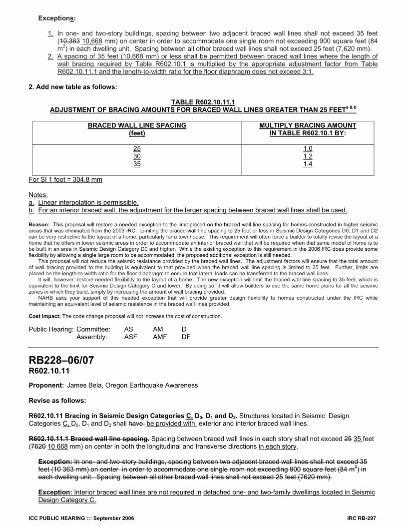
RB227–06/07 R602.10.11.1, Table R602.10.11.1 (New) Proponent: Ed Sutton, National Association of Home Builders (NAHB) 1. Revise as follows: R602.10.11.1 Braced wall line spacing. Spacing between braced wall lines in each story shall not exceed 25 feet (7620 mm) on center in both the longitudinal and transverse directions.
ICC PUBLIC HEARING ::: September 2006 IRC RB-297
Exceptions:
1. In one- and two-story buildings, spacing between two adjacent braced wall lines shall not exceed 35 feet (10,363 10,668 mm) on center in order to accommodate one single room not exceeding 900 square feet (84 m2) in each dwelling unit. Spacing between all other braced wall lines shall not exceed 25 feet (7,620 mm).
2. A spacing of 35 feet (10,668 mm) or less shall be permitted between braced wall lines where the length of wall bracing required by Table R602.10.1 is multiplied by the appropriate adjustment factor from Table R602.10.11.1 and the length-to-width ratio for the floor diaphragm does not exceed 3:1.
2. Add new table as follows:
TABLE R602.10.11.1 ADJUSTMENT OF BRACING AMOUNTS FOR BRACED WALL LINES GREATER THAN 25 FEETa & b
BRACED WALL LINE SPACING (feet)
MULTIPLY BRACING AMOUNT IN TABLE R602.10.1 BY:
25 30 35
1.0 1.2 1.4
For SI 1 foot = 304.8 mm
Notes: a. Linear interpolation is permissible. b. For an interior braced wall, the adjustment for the larger spacing between braced wall lines shall be used. Reason: This proposal will restore a needed exception to the limit placed on the braced wall line spacing for homes constructed in higher seismic areas that was eliminated from the 2003 IRC. Limiting the braced wall line spacing to 25 feet or less in Seismic Design Categories D0, D1 and D2 can be very restrictive to the layout of a home, particularly for a townhouse. This requirement will often force a builder to totally revise the layout of a home that he offers in lower seismic areas in order to accommodate an interior braced wall that will be required when that same model of home is to be built in an area in Seismic Design Category D0 and higher. While the existing exception to this requirement in the 2006 IRC does provide some flexibility by allowing a single large room to be accommodated, the proposed additional exception is still needed. This proposal will not reduce the seismic resistance provided by the braced wall lines. The adjustment factors will ensure that the total amount of wall bracing provided to the building is equivalent to that provided when the braced wall line spacing is limited to 25 feet. Further, limits are placed on the length-to-width ratio for the floor diaphragm to ensure that lateral loads can be transferred to the braced wall lines. It will, however, restore needed flexibility to the layout of a home. The new exception will limit the braced wall line spacing to 35 feet, which is equivalent to the limit for Seismic Design Category C and lower. By doing so, it will allow builders to use the same home plans for all the seismic zones in which they build, simply by increasing the amount of wall bracing provided. NAHB asks your support of this needed exception that will provide greater design flexibility to homes constructed under the IRC while maintaining an equivalent level of seismic resistance in the braced wall lines provided. Cost Impact: The code change proposal will not increase the cost of construction. Public Hearing: Committee: AS AM D Assembly: ASF AMF DF
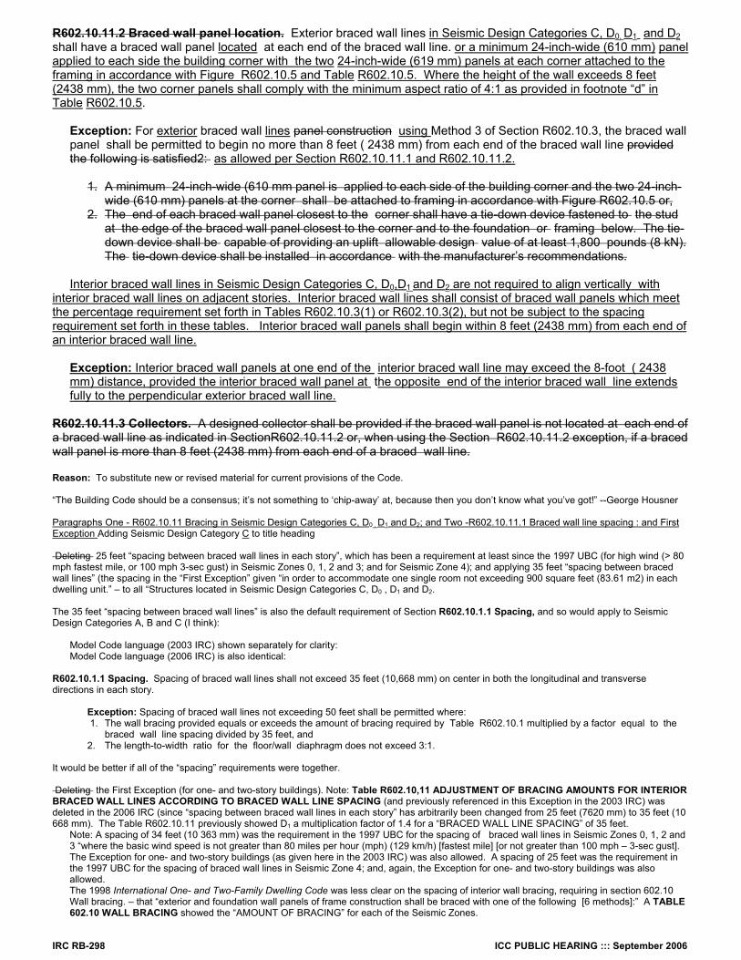
RB228–06/07 R602.10.11 Proponent: James Bela, Oregon Earthquake Awareness Revise as follows: R602.10.11 Bracing in Seismic Design Categories C, D0, D1 and D2. Structures located in Seismic Design Categories C, D0, D1 and D2 shall have be provided with exterior and interior braced wall lines. R602.10.11.1 Braced wall line spacing. Spacing between braced wall lines in each story shall not exceed 25 35 feet (7620 10 668 mm) on center in both the longitudinal and transverse directions in each story.
Exception: In one- and two-story buildings, spacing between two adjacent braced wall lines shall not exceed 35 feet (10 363 mm) on center in order to accommodate one single room not exceeding 900 square feet (84 m2) in each dwelling unit. Spacing between all other braced wall lines shall not exceed 25 feet (7620 mm).
Exception: Interior braced wall lines are not required in detached one- and two-family dwellings located in Seismic Design Category C.
IRC RB-298 ICC PUBLIC HEARING ::: September 2006
R602.10.11.2 Braced wall panel location. Exterior braced wall lines in Seismic Design Categories C, D0, D1 and D2 shall have a braced wall panel located at each end of the braced wall line. or a minimum 24-inch-wide (610 mm) panel applied to each side the building corner with the two 24-inch-wide (619 mm) panels at each corner attached to the framing in accordance with Figure R602.10.5 and Table R602.10.5. Where the height of the wall exceeds 8 feet (2438 mm), the two corner panels shall comply with the minimum aspect ratio of 4:1 as provided in footnote “d” in Table R602.10.5.
Exception: For exterior braced wall lines panel construction using Method 3 of Section R602.10.3, the braced wall panel shall be permitted to begin no more than 8 feet ( 2438 mm) from each end of the braced wall line provided the following is satisfied2: as allowed per Section R602.10.11.1 and R602.10.11.2.
1. A minimum 24-inch-wide (610 mm panel is applied to each side of the building corner and the two 24-inch-
wide (610 mm) panels at the corner shall be attached to framing in accordance with Figure R602.10.5 or, 2. The end of each braced wall panel closest to the corner shall have a tie-down device fastened to the stud
at the edge of the braced wall panel closest to the corner and to the foundation or framing below. The tie-down device shall be capable of providing an uplift allowable design value of at least 1,800 pounds (8 kN). The tie-down device shall be installed in accordance with the manufacturer’s recommendations.
Interior braced wall lines in Seismic Design Categories C, D0,D1 and D2 are not required to align vertically with
interior braced wall lines on adjacent stories. Interior braced wall lines shall consist of braced wall panels which meet the percentage requirement set forth in Tables R602.10.3(1) or R602.10.3(2), but not be subject to the spacing requirement set forth in these tables. Interior braced wall panels shall begin within 8 feet (2438 mm) from each end of an interior braced wall line.
Exception: Interior braced wall panels at one end of the interior braced wall line may exceed the 8-foot ( 2438 mm) distance, provided the interior braced wall panel at the opposite end of the interior braced wall line extends fully to the perpendicular exterior braced wall line.
R602.10.11.3 Collectors. A designed collector shall be provided if the braced wall panel is not located at each end of a braced wall line as indicated in SectionR602.10.11.2 or, when using the Section R602.10.11.2 exception, if a braced wall panel is more than 8 feet (2438 mm) from each end of a braced wall line. Reason: To substitute new or revised material for current provisions of the Code. “The Building Code should be a consensus; it’s not something to ‘chip-away’ at, because then you don’t know what you’ve got!” --George Housner Paragraphs One - R602.10.11 Bracing in Seismic Design Categories C, D0 , D1 and D2; and Two -R602.10.11.1 Braced wall line spacing : and First Exception Adding Seismic Design Category C to title heading Deleting 25 feet “spacing between braced wall lines in each story”, which has been a requirement at least since the 1997 UBC (for high wind (> 80 mph fastest mile, or 100 mph 3-sec gust) in Seismic Zones 0, 1, 2 and 3; and for Seismic Zone 4); and applying 35 feet “spacing between braced wall lines” (the spacing in the “First Exception” given “in order to accommodate one single room not exceeding 900 square feet (83.61 m2) in each dwelling unit.” – to all “Structures located in Seismic Design Categories C, D0 , D1 and D2. The 35 feet “spacing between braced wall lines” is also the default requirement of Section R602.10.1.1 Spacing, and so would apply to Seismic Design Categories A, B and C (I think):
Model Code language (2003 IRC) shown separately for clarity: Model Code language (2006 IRC) is also identical:
R602.10.1.1 Spacing. Spacing of braced wall lines shall not exceed 35 feet (10,668 mm) on center in both the longitudinal and transverse directions in each story.
Exception: Spacing of braced wall lines not exceeding 50 feet shall be permitted where: 1. The wall bracing provided equals or exceeds the amount of bracing required by Table R602.10.1 multiplied by a factor equal to the
braced wall line spacing divided by 35 feet, and 2. The length-to-width ratio for the floor/wall diaphragm does not exceed 3:1.
It would be better if all of the “spacing” requirements were together. Deleting the First Exception (for one- and two-story buildings). Note: Table R602.10,11 ADJUSTMENT OF BRACING AMOUNTS FOR INTERIOR BRACED WALL LINES ACCORDING TO BRACED WALL LINE SPACING (and previously referenced in this Exception in the 2003 IRC) was deleted in the 2006 IRC (since “spacing between braced wall lines in each story” has arbitrarily been changed from 25 feet (7620 mm) to 35 feet (10 668 mm). The Table R602.10.11 previously showed D1 a multiplication factor of 1.4 for a “BRACED WALL LINE SPACING” of 35 feet.
Note: A spacing of 34 feet (10 363 mm) was the requirement in the 1997 UBC for the spacing of braced wall lines in Seismic Zones 0, 1, 2 and 3 “where the basic wind speed is not greater than 80 miles per hour (mph) (129 km/h) [fastest mile] [or not greater than 100 mph – 3-sec gust]. The Exception for one- and two-story buildings (as given here in the 2003 IRC) was also allowed. A spacing of 25 feet was the requirement in the 1997 UBC for the spacing of braced wall lines in Seismic Zone 4; and, again, the Exception for one- and two-story buildings was also allowed. The 1998 International One- and Two-Family Dwelling Code was less clear on the spacing of interior wall bracing, requiring in section 602.10 Wall bracing. – that “exterior and foundation wall panels of frame construction shall be braced with one of the following [6 methods]:” A TABLE 602.10 WALL BRACING showed the “AMOUNT OF BRACING” for each of the Seismic Zones.

ICC PUBLIC HEARING ::: September 2006 IRC RB-299
Paragraph Five – R602.10.11.2 Braced wall panel locations: Adding Seismic Design Category C to the requirements. Adding text merging the requirements of the Second Exception (2006 IRC) , subparagraphs 1. and 2. (pertaining to exterior braced wall lines) within the body of one main text. The Exception specifies the requirements for 1. “minimum 24 inch wide (610 mm) panels” applied to each side of the building corner; and 2. “a tie-down device fastened to the stud at the edge of the braced wall panel closest to the corner and to the foundation or framing below” – in the cases where the braced wall panel is not located at the end . . . and “is permitted to begin no more than 8 feet (2438 mm) from each end of the braced wall line.” Adding a new footnote d to Table R602.10.5 LENGTH REQUIREMENTS FOR BRACED WALL PANELS IN A CONTINUOUSLY SHEATHED WALL. – which reads: “d. Corners sheathed in accordance with Section R602.10.5 [Continuous structural panel sheathing.] and Figure R602.10.5 [ EXTERIOR CORNER FRAMING FOR CONTINUOUS STRUCTURAL PANEL SHEAHING; SHOWING REQUIRED STUD-TO-STUD NAILING] shall be permitted to have a 4:1 aspect ratio.” Adding text referencing new code sections (as specified in the 2005 OREGON RESIDENTIAL SPECIALTY CODE): R602.10.11.1 Two or less horizontally attached units. and R602.10.11.2 Three or more horizontally attached units. -- which contain additional provisions for “Braced panels that are not located at the end of a braced wall line.” Paragraphs Nine and Ten: Interior Braced Wall Line Exceptions Note: R602.10.11.2 Braced wall panel location. – only refers to “exterior” braced wall lines. Since the 2006 IRC no longer preserves the long honored text in Table R602.10.1 WALL BRACING of previous codes: “located at each end” (replacing it with: “located in accordance with Section R602.10 [Wall bracing.] ) – it is not clear what the actual requirements are for interior braced wall panels located at the ends of interior braced wall lines. Could one invoke the “shall begin no more than 12.5 feet ( 3810 mm) from each end of the braced wall line” of R602.10.1 Braced wall lines. ? Paragraph Nine adds new text specific to interior braced wall lines regarding vertical alignment with interior braced wall lines on adjacent stories, end locations with respect to perpendicular exterior braced wall lines, panel spacing requirements. Interior braced wall panels are permitted to begin within 8 feet (2438 mm) from each end of an interior braced wall line, but without the additional seismic detailing requirements (such as “corner panel reinforcement” or “tie-down devices”. A further Exception (Paragraph Ten) allows (without any need for “a designed collector”: Exception: Interior braced wall panels at one end of the interior braced wall line may exceed the 8-foot (2438 mm) distance, provided the interior braced wall panel at the opposite end of the interior braced wall line extends fully to the perpendicular exterior braced wall line. Section 2320.11.3 Bracing. -- in the 1997 UBC apparently treated exterior and interior braced wall panels in the same way; and it referenced Table 23-IV-C-1---BRACED WALL PANELS1. Footnote 1 CLARIFIED: “This table specifies minimum requirements for braced panels which form interior or exterior braced wall lines.” It allowed both exterior and interior braced wall panels to ”start at not more than 8 feet (2438 mm) from each end of a braced wall line,” as long as multi-story buildings had the stated “percentage of building length”. “Out-of-plane offsets of braced wall panels may occur at both interior and exterior braced wall lines. As noted in this section of the code, offsets
of up to 4 feet may occur between the braced wall panels in any given braced wall line. However, if more than one offset occurs in the same braced wall line, the intent of the code is that the sum of the offsets should not exceed 4 feet. For interior braced wall panels, importance should be placed on adequate connection of the wall plates to the roof, ceiling and/or floor structural system.
“In multistory structures, braced wall panels should occur at the same vertical location along the length of the braced wall line (i.e. the braced panels should ‘stack’ one above the other). However, this condition is seen to be a severe constraint on the architectural layout of the building. Therefore, the code allows a 4-foot maximum in-plane offset under conventional construction. An important condition to keep in mind when exercising this ‘exception’ is to limit the amount of in-plane offset of braced panels adjacent to an opening to 1 foot (i.e. upper floor braced wall panels are permitted to extend up to 1 foot over an opening in the wall below). If the upper braced wall panel extends more than 1 foot over an opening below, then the provisions of Section 2320.5.4.3 [Unusually shaped buildings.] shall also apply. “Prior to the 1994 edition of the code, placement of braced wall panels near the ends of braced wall lines were to occur ‘as near thereto as possible.’ This provision was difficult to enforce and nonuniformity in code enforcement construction was more prevalent. To increase uniformity, the code now requires wall bracing to start at no more than 8 feet from each end of a braced wall line. Also, the code requires braced panels within a braced wall line to occur in line with one another. However, an offset in the bracing of one panel to another of 4 feet is permitted.”
Placing these braced panels within 8 feet of the ends of braced wall lines and additional panels within each 25-foot module of wall length is demed adequate to resist wind loads and/or earthquake loads in Seismic Zones 0, 1 and 2A. However, in Seismic Zones 2B, 3 and 4, this minimum number of panels may not be enough unless the second story of a three-story building or the first story of a two-story building specifically has a minimum of 25 percent of wall in required braced panels. In addition, in these seismic zones, the first story of a three-story building must be at least 40 percent braced panels. Another way of saying this is that the complying two-story ‘building’ is stacked on a properly braced first story of a three story building, or the complying one-story ‘building’ is stacked on the properly braced first story of a two-story building.” * *Conventional Construction Provisions of the Uniform Building Code: An illustrated guide and commentary to the conventional wood-framing construction provisions found in Chapter 23 of the 1997 Uniform Building Code (U.B.C.), International Conference of Building Officials, Whittier, CA, 1999, p. 116. Interpretation: “The whole is greater than the sum of its [braced wall panel] parts.-- Aristotole R602.10.11 Bracing in Seismic Design Categories D0 , D1 and D2. – is not totally clear on how to treat interior braced panels within interior braced wall lines, both horizontally as well as vertically. R602.10.11 Bracing in Seismic Design Categories D0 , D1 and D2. – cites both “exterior and interior” braced wall lines. However, R602.10.11.2 Braced wall panel locations. And R602.10.11.3 Collectors. Only reference language that refers to “exterior” braced wall lines. It is not known whether this is errata or intentional. The best way to brace the exterior wall is to have the interior braced wall panel at each end of the interior braced wall line. This would significantly improve and balance the overall “lateral-force-resisting-system” performance of structures in the major earthquakes which are both possible and likely. For earthquake performance, it is best if the resisting elements have similar stiffnesses – to more uniformly share the earthquake loads. Although it seems like a reasonable idea, I’m not convinced we really know what real earthquake performance we’ll see if we start mixing “nailed braced wall panels” and “tie-down devices” in a non-engineered way throughout what can be today some pretty large structures. In any case, interior braced wall lines do form a “corner” with the exterior walls; at which point the difference between “a minimum 24-inch-wide (610 mm) panel” (applied on both sides of the corner – per Second Exception, 1.) and the minimum “48 inches (1219 mm)” required for a braced wall panel is not a big inconvenience, for a non-engineered approach.

IRC RB-300 ICC PUBLIC HEARING ::: September 2006
Paragraph Eleven: R602.10.11.3 Collectors. Deleting in its entirety the final paragraph, requiring that: R602.10.11.3 Collectors. A designed collector shall be provided if a braced wall panel is not located at each end of a braced wall line as indicated in SectionR602.10.11.2 or, when using the Section R602.10.11.2 exception, if a braced wall panel is more than 8 feet (2438 mm) from each end of a braced wall line.” See also related proposed code change to Section R602.10.1.1 Spacing. State of Oregon Amendment to 2000 IRC: Code Change Proponent – Patrick Bridges: on behalf of Oregon Building Industry Association (OBIA) and Oregon Building Officials Association (OBOA) State of Oregon Amendment to 2003 IRC: adopted as the “base code” for 2005 OREGON RESIDENTIAL SPECIALTY CODE (effective date of April 1, 2005) State of Oregon Amendment to 2000 IRC: Code Change Proponent – Patrick Bridges: on behalf of Oregon Building Industry Association (OBIA) and Oregon Building Officials Association (OBOA) State of Oregon Amendment to 2003 IRC: adopted as the “base code” for 2005 OREGON RESIDENTIAL SPECIALTY CODE (effective date of April 1, 2005) Code Change Proponent – Richard Rogers, Structural Program Chief, Oregon Building Codes Division: on behalf of Oregon Building Codes Division These changes to model code language of the International Residential Code (IRC) were effected by basically just “voting them in” by members of the Oregon Building Codes Division’s (a) code development committees; (b) appropriate Advisory Boards; and (c) finally the concurrence of the BCD Administrator. Where technical supporting information was presented in the Oregon code change process, that same information is presented here. Where none was given in the Oregon code change process, the “supporting information” is “voting yes” in support by all of the above - to change the model code. Finally, one reasonably expects that the Board of Directors of the ICC, the “People Helping People Build a Safer World™” see nothing in conflict with the Vision, Mission and Values of the ICC, since they agreeably have printed them under their copyright ownership now for two code cycles (2003 & 2005): Vision: Protecting the health, safety, and welfare of people by creating better buildings and safer communities. Mission: Providing the highest quality codes, standards, products, and services for all concerned with the safety and performance of the built environment Values: Customer value, Integrity and trust, Member-focus, Professionalism, Public service, Quality The fact that these revisions do not conform to ASCE 7-05, below, therefore should be considered “non-persuasive” – which presumably is the concurring view of the ICC Board and its CEO, James Lee Witt. Even though a “uniform adoption would lead to consistent code enforcement and higher quality construction,” the continued evisceration of the ICC copyright protections can continue to provide, well, “A New Era of Building and Fire Safety” -- throughout the seismic regions of the West, and particularly the Pacific Northwest, which is subject to Magnitude 9 subduction zone earthquakes, as have occurred in Chile (1960), Alaska (1964), and Sumatra (2004).
SECTION 11 SEISMIC DESIGN CRITERIA
11.1.4 Alternate Materials and Methods of Construction. Alternate materials and methods of construction to those prescribed in the seismic provisions of this standard shall not be used unless approved by the authority having jurisdiction. Substantiating evidence shall be submitted demonstrating that the proposed alternate, for the purpose intended, will be at least equal in strength, durability, and seismic resistance.
Bibliography: ASCE 7-05, Minimum Design Loads for Buildings and Other Structures, including Supplement No. 1; American Society of Civil Engineers Structural Engineering Institute, Reston, VA. 2005 OREGON RESIDENTIAL SPECIALTY CODE, 2005 Edition (Effective date April 1, 2005), copyright 2005 by International Code Council, Inc., Falls Church, VA., 516 p. + 6 p. errata. State of Oregon One- and Two-Family Dwelling Specialty Code, 2003 Edition, (Effective date April 1, 2003, copyright 2002 by International Code Council, Inc., Falls Church, VA., 350 p. (Remove 2000 IRC Page / Insert 2003 Oregon Page) Bela, J. (2006). Building Codes Division Public Hearing February 21, 2006: Oregon’s Building Codes Adoption Process Rules, Oral Testimony, 10 p. Bela, J. (2006). Building Codes Division Public Hearing February 21, 2006: Oregon’s Building Codes Adoption Process Rules, Additional Written Testimony, 23 p. Bela, J. (2002). Building Codes Division Public Hearing September 17, 2002: Adopting 2000 Edition of International Residential Code “Approved as amended/use IRC as base document/allow for Oregon amendments”, Written Testimony (FAX) withdrawing Code Change Proposal IRC-02-01 to adopt 2000 Edition of the IRC, 4 p. Cost Impact: The code change proposal will not increase the cost of construction. Public Hearing: Committee: AS AM D Assembly: ASF AMF DF
RB229–06/07 R602.10.11.1 (New) Proponent: James Bela, Oregon Earthquake Awareness Add new text as follows: R602.10.11.1 Bracing in Seismic Design Categories D0, D1 and D2.R602.10.11.1 Two or less horizontally attached units. Braced panels that are not located at the end of a braced wall line shall comply with the following provisions:

ICC PUBLIC HEARING ::: September 2006 IRC RB-301
1. In walls sheathed in accordance with Table R602.10.3(2) the end of the braced wall panel closest to the corner shall have a tie-down device fastened to the stud at the edge of the braced wall panel closest to the corner and to the foundation or an equivalent cross section of stud in the wall below. In a one-story building, or the top of a two or three story building, the tie-down device shall be capable of providing an uplift allowable
design value of at least 1,800 pounds (817 kg). In the first of a two story building or a second of a three story building, the tie-down device shall be capable of providing an uplift allowable design value of at least 3,000 pounds (1361 kg). In the first of a three story building, the tie-down device shall be capable of providing an uplift allowable design value of at least 4,200 pounds (1905 kg). The tie-down device shall be installed in accordance with the manufacturer’s recommendations.
2. In walls sheathed in accordance with Table R602.10.3(1) the end of each side of the braced panel closest to the corner shall have a tie-down device fastened to each end stud and to the foundation or an equivalent cross section of stud in the wall below. In a one story building, top of a two or three story building, the tie-down device shall be capable of providing an uplift allowable design value of at least 1,800 pounds (817 kg). In a first of a two story building or a second of a three story building, the tie-down device shall be capable of providing an uplift allowable design value of at least 3,000 pounds (1361 kg). In the first of a three story building, the tie-down device shall be capable of providing an uplift allowable design value of at least 4,200 pounds (1905 kg). The tie-down device shall be installed in accordance with the manufacturer’s recommendations. When a braced wall line exceeds the minimum percentage as outlined in Table R602.10.3(1) by at least 50%, the tie- down device shall not be required for the first of a one or the top of a two story building.
Exception: The required uplift capacities for tie-down devices may be reduced by 25 percent for braced panels installed within Seismic Design Category C except in areas exposed to Columbia River Gorge as per Figure R301.2(4).
(Renumber subsequent sections) Reason: To substitute new or revised material for current provisions of the Code. This is a new section R602.10.11.1 Two or less horizontally attached units. - and it adds the “tie-down device” requirements of the newly revised section R602.10.11.2 Braced wall panel location. (which is now a subsection of R602.10.11 Bracing in Seismic Design Categories D0, D1 and D2. – of the 2006 IRC) under Exception, No. 2 – in a new and separate (and renumbered) section. Formerly, the above cited “tie-down device” requirements were provided in the Second Exception, No. 2 (Paragraph Six) of R602.10.11 Bracing in Seismic Design Categories D1 and D2. (of the 2003 IRC). It apparently pertains to all braced wall panels (exterior and interior) “that are not located at the end of a braced wall line”. It provides specifically stated higher “uplift allowable design values” for lower floors in multi-story buildings. These follow the design values indicated in R602.10.6 Alternate braced wall panels. - for up to two-story buildings; and these design values incorporate the changes Oregon has made to the model code language to permit alternate braced wall panels on upper stories of multi-story buildings ( See Code Change Proposal to Section R602.10.6 Alternate braced wall panels.) An Exception permitting “the required uplift capacities for tie-down devices may be reduced by 25% for braced panels installed within Seismic Design Category C except in areas exposed to Columbia River Gorge as per Figure R301.2(4)” is carried forward into this new section from Oregon’s modification to Section R602.10.6 Alternate braced wall panels. – which has the exact same exception. “A minimum 24-inch-wide (610mm) panel applied to each side of the building corner with the two 24-inch-wide (610 mm) panels at each corner attached to the framing in accordance with Figure R602.10.5” is always required for Exterior braced wall lines; and as indicated (by new text) in Code Change Proposal to Section R602.10.11. This is the requirement of: (a) the Exception, No. 1 (Paragraph Three) of R602.10.11.1 Braced wall panel location. - of the newly revised 2006 IRC; and (b) the Second Exception, No. 1 (Paragraph Five) of R602.10.11 Bracing in Seismic Design Categories D1 and D2. - of the 2003 IRC. Two TABLES -- SEGMENTAL WALL BRACING and WALL BRACING WITH CONTINUOUSLY SHEATHED WOOD STRUCTURAL PANELS -- show how the different design values apply, as compared to story location, Seismic Design Category (SDC) and Amount of Bracing (% of braced wall line). The requirements of section R602.10.6 Alternate braced wall panels. – are also shown for further comparison. When compared in this fashion, it is questionable to me whether we really know what we are doing! The difference between “A minimum 24-inch-wide (610mm) panel applied to each side of the building corner” (First Exception, No. 1 in R602.10.11.2 – 2006 IRC; and Second Exception, No. 1 – 2003 IRC) and an “alternate braced wall panel” is only 8 inches, yet the requirements are very different. For reliable earthquake performance (in design-level earthquake events that we have not experienced yet) in non-engineered construction, it is preferable to require the braced wall panels “at each end period!” These Exceptions really become a nightmare for designers, and it is problematical whether they are actually constructable in the field. Finally, an Exception permits that: “the required uplift capacities for tie-down devices may be reduced by 25% for braced panels installed within Seismic Design Category C except in areas exposed to Columbia River Gorge as per Figure R301.2(4).” While it is not clear if there is clear-cut justification for this exception, it can be noted that the AMOUNT OF BRACING (% of braced wall line) of TABLE R602.10.1 WALL BRACING shows that the difference in (% of braced wall line) between Seismic Design Categories ( D0 - D1) and D2 is about 22-25%. For Seismic Design Category C (when compared to Seismic Design Categories ( D0 - D1) and D2 , it is more variable (20-33% less); as shown below. It should be noted that the First Printing of the 2006 IRC has the AMOUNT OF BRACING for Category C (One story / Top of two or three story = “30% of braced wall line for Method 3”) and (First story of two story / Second story of three story = “16% of braced wall line for Method 3”) reversed. It is not certain whether the reduction in the AMOUNT OF BRACING (% of braced wall line) in Seismic Design Category C might actually lead to larger uplift forces due to earthquake shaking (because of the reduced lateral capacity) – in which case the Exception given here would be counterproductive. A third Table : WALL BRACING COMPARISONS FOR SEISMIC DESIGN CATEGORIES C, D0 – D1, AND D2 – shows by what “percentage” the % of braced wall line for SDC C is less than for either D2 or D0 – D1. ( See also Code Change Proposal to insert a new Section R602.10.11.2 Three or more horizontally attached units). State of Oregon Amendment to 2000 IRC: Code Change Proponent – Patrick Bridges: on behalf of Oregon Building Industry Association (OBIA) and Oregon Building Officials Association (OBOA) State of Oregon Amendment to 2003 IRC: adopted as the “base code” for 2005 OREGON RESIDENTIAL SPECIALTY CODE (effective date of April 1, 2005) Code Change Proponent – Richard Rogers, Structural Program Chief, Oregon Building Codes Division: on behalf of Oregon Building Codes Division

IRC RB-302 ICC PUBLIC HEARING ::: September 2006
These changes to model code language of the International Residential Code (IRC) were effected by basically just “voting them in” by members of the Oregon Building Codes Division’s (a) code development committees; (b) appropriate Advisory Boards; and (c) finally the concurrence of the BCD Administrator. Where technical supporting information was presented in the Oregon code change process, that same information is presented here. Where none was given in the Oregon code change process, the “supporting information” is “voting yes” in support by all of the above - to change the model code. Finally, one reasonably expects that the Board of Directors of the ICC, the “People Helping People Build a Safer World™” see nothing in conflict with the Vision, Mission and Values of the ICC, since they agreeably have printed them under their copyright ownership now for two code cycles (2003 & 2005): Vision: Protecting the health, safety, and welfare of people by creating better buildings and safer communities. Mission: Providing the highest quality codes, standards, products, and services for all concerned with the safety and performance of the built environment Values: Customer value, Integrity and trust, Member-focus, Professionalism, Public service, Quality The fact that these revisions do not conform to ASCE 7-05, below, therefore should be considered “non-persuasive” – which presumably is the concurring view of the ICC Board and it’s CEO, James Lee Witt. Even though a “uniform adoption would lead to consistent code enforcement and higher quality construction,” the continued evisceration of the ICC copyright protections can continue to provide, well, “A New Era of Building and Fire Safety” -- throughout the seismic regions of the West, and particularly the Pacific Northwest, which is subject to Magnitude 9 subduction zone earthquakes, as have occurred in Chile (1960), Alaska (1964), and Sumatra (2004).
SECTION 11 SEISMIC DESIGN CRITERIA
11.1.4 Alternate Materials and Methods of Construction. Alternate materials and methods of construction to those prescribed in the seismic provisions of this standard shall not be used unless approved by the authority having jurisdiction. Substantiating evidence shall be submitted demonstrating that the proposed alternate, for the purpose intended, will be at least equal in strength, durability, and seismic resistance.
Bibliography: ASCE 7-05, Minimum Design Loads for Buildings and Other Structures, including Supplement No. 1; American Society of Civil Engineers Structural Engineering Institute, Reston, VA. 2005 OREGON RESIDENTIAL SPECIALTY CODE, 2005 Edition (Effective date April 1, 2005), copyright 2005 by International Code Council, Inc., Falls Church, VA., 516 p. + 6 p. errata. State of Oregon One- and Two-Family Dwelling Specialty Code, 2003 Edition, (Effective date April 1, 2003, copyright 2002 by International Code Council, Inc., Falls Church, VA., 350 p. (Remove 2000 IRC Page / Insert 2003 Oregon Page) Bela, J. (2006). Building Codes Division Public Hearing February 21, 2006: Oregon’s Building Codes Adoption Process Rules, Oral Testimony, 10 p. Bela, J. (2006). Building Codes Division Public Hearing February 21, 2006: Oregon’s Building Codes Adoption Process Rules, Additional Written Testimony, 23 p. Bela, J. (2002). Building Codes Division Public Hearing September 17, 2002: Adopting 2000 Edition of International Residential Code “Approved as amended/use IRC as base document/allow for Oregon amendments”, Written Testimony (FAX) withdrawing Code Change Proposal IRC-02-01 to adopt 2000 Edition of the IRC, 4 p. Cost Impact: The code change proposal will not increase the cost of construction. Public Hearing: Committee: AS AM D Assembly: ASF AMF DF
RB230–06/07 R602.10.11.2 (New) Proponent: James Bela, Oregon Earthquake Awareness Add new text as follows: R602.10.11.2 Three or more horizontally attached units. Braced panels that are not located at the end of a braced wall line shall comply with the following provisions:
1. In walls sheathed in accordance with Table R602.10.3(2) the end of the braced wall panel closest to the corner shall have a tie-down device fastened to the stud at the edge of the braced wall panel closest to the corner and to the foundation or an equivalent cross section of stud in the wall be low. In the first of a two story building or second of three story building, the tie-down device shall be capable of providing an uplift allowable design value of at least 1,800 pounds ( 817 kg). In the first of a three story building, the tie-down device shall be capable of providing an uplift allowable design value of at least 3,000 pounds (1361 kg). The tie-down device shall be installed in accordance with the manufacturer’s recommendations.
2. In walls sheathed in accordance with Table R602.10.3(1), the end of each side of the braced panel closest to the corner shall have a tie-down device fastened to each end stud and to the foundation or an equivalent cross section of stud in the wall be low. In the first of a two story building or second of a three story building, the tie-down device shall be capable of providing an uplift allowable design value of at least 1,800 pounds (817 kg). In the first of a three story building, the tie-down device shall be capable of providing an uplift allowable design value of at least 3,000 pounds (1361 kg). The tie-down device shall be installed in accordance with the manufacturer’s recommendations.
No tie-down device is required for a one story building, the top of a two or top of a three story building.

ICC PUBLIC HEARING ::: September 2006 IRC RB-303
Exception: The required uplift capacities for tie-down devices may be reduced by 25 percent for braced panels installed within Seismic Design Category C except in areas exposed to Columbia River Gorge as per Figure R301.2(4).
(Renumber subsequent section) Reason: To substitute new or revised material for current provisions of the Code. This is a new section R602.10.11.2 Three or more horizontally attached units. and it adds the “tie-down device” requirements of the newly revised section R602.10.11.2 Braced wall panel location. (which is now a subsection of R602.10.11 Bracing in Seismic Design Categories D0, D1 and D2. – of the 2006 IRC) under Exception, No. 2 – in a new and separate (and renumbered) section. Formerly, the above cited “tie-down device” requirements were provided in the Second Exception, No. 2 (Paragraph Six) of R602.10.11 Bracing in Seismic Design Categories D1 and D2. (of the 2003 IRC). It apparently pertains to all braced wall panels (exterior and interior) “that are not located at the end of a braced wall line”. It provides specifically stated higher “uplift allowable design values” for lower floors in multistory buildings – with “three or more horizontally attached units.” But for this case, the design uplift capacities are reduced by 40% (for “First story of two story / Second of three story”); and by about 29% (for “First story of three story’) from those specified in section R602.10.11.1 two or less horizontally attached units (new). The result is, in general, that the “uplift allowable design values” are either eliminated entirely – for the case of “One story, Top of two story or three story”; or they are reduced by 900 1200 pounds (1980 – 2640 kg) for the cases “First story of three story” and First story of two story / Second of three story” for this case of “three or more horizontally attached units’, as compared to “two or less horizontally attached units.” For new section R602.10.11.1 Two or less horizontally attached units. (new) These tie-down device design values follow the design values indicated in R602.10.6 Alternate braced wall panels. for up to two story buildings; and these design values incorporate the changes Oregon has made to the model code language to permit alternate braced wall panels on upper stories of multistory buildings ( See Code Change Proposal to Section R602.10.6 Alternate braced wall panels.) An Exception permitting “the required uplift capacities for tie-down devices may be reduced by 25% for braced panels installed within Seismic Design Category C except in areas exposed to Columbia River Gorge as per Figure R301.2(4)” is carried forward into this new section from Oregon’s modification to Section R602.10.6 Alternate braced wall panels. – which has the exact same exception. For new section R602.10.11.2 Three or more horizontally attached units. (new) These tie-down device design values are now either eliminated entirely ( i.e., “No tie-down device is required” for: one story, top of two story or three story); or they are reduced by 1200 pounds (544 kg) (First story of two story, Second of three story; First story of three story) – as compared to the “uplift allowable design values” for “Two or less horizontally attached units.” See TABLES: WALL BRACING COMPARISONS FOR SEISMIC DESIGN CATEGORIES C, D0 D1 AND D2 / Two or less horizontally attached units / < Three or more horizontally attached units > 3+ ); SEGMENTAL WALL BRACINGa / Two or less horizontally attached units / < Three or more horizontally attached units > 3+ ); WALL BRACING WITH CONTINUOUSLY SHEATHED WOOD STRUCT. PANELSa / Two or less horizontally attached units / < Three or more horizontally attached units > 3+ . “A minimum 24inchwide (610 mm) panel applied to each side of the building corner with the two 24inchwide (610 mm) panels at each corner attached to the framing in accordance with Figure R602.10.5” is always required for Exterior braced wall lines; and as indicated (by new text) in Code Change Proposal to Section R602.10.11. This is the requirement of: (a) the Exception, No. 1 (Paragraph Three) of R602.10.11.1 Braced wall panel location. of the newly revised 2006 IRC; and (b) the Second Exception, No. 1 (Paragraph Five) of R602.10.11 Bracing in Seismic Design Categories D1 and D2. of the 2003 IRC. Two TABLES – SEGMENTAL WALL BRACING and WALL BRACING WITH CONTINUOUSLY SHEATHED WOOD STRUCTURAL PANELS show how the different design values apply, as compared to story location, Seismic Design Category (SDC) and Amount of Bracing (% of braced wall line). The requirements of section R602.10.6 Alternate braced wall panels. – are also shown for further comparison. When compared in this fashion, it is questionable to me whether we really know what we are doing! The difference between “A minimum 24inchwide (610mm) panel applied to each side of the building corner” (First Exception, No. 1 in R602.10.11.2 – 2006 IRC; and Second Exception, No. 1 – 2003 IRC) and an “alternate braced wall panel” is only 8 inches, yet the requirements are very different. In the case of this new section R602.10.11.2 Three or more horizontally attached units. – no “tie-down device” is required at all for a one story building; whereas an alternate braced panel (substituted for the regular “braced wall panel closest to the corner” would require two 1800 pound (817 kg) tie-down devices, per the model code (2000, 2003 and 2006 IRC). For reliable earthquake performance (in design level earthquake events that we have not experienced yet) in non engineered construction, it is preferable to require the braced wall panels “at each end period!” These Exceptions really become a nightmare for designers, and it is problematical whether they are actually constructable in the field. Finally, an Exception permits that: “the required uplift capacities for tie-down devices may be reduced by 25% for braced panels installed within Seismic Design Category C except in areas exposed to Columbia River Gorge as per Figure R301.2(4).” While it is not clear if there is clear cut justification for this exception, it can be noted that the AMOUNT OF BRACING (% of braced wall line) of TABLE R602.10.1 WALL BRACING shows that the difference in (% of braced wall line) between Seismic Design Categories ( D0 D1) and D2 is about 2225%. For Seismic Design Category C (when compared to Seismic Design Categories ( D0 D1) and D2 , it is more variable (2033% less); as shown below. It should be noted that the First Printing of the 2006 IRC has the AMOUNT OF BRACING for Category C (One story / Top of two or three story = “30% of braced wall line for Method 3”) and (First story of two story / Second story of three story = “16% of braced wall line for Method 3”) reversed. It is not certain whether the reduction in the AMOUNT OF BRACING (% of braced wall line) in Seismic Design Category C might actually lead to larger uplift forces due to earthquake shaking (because of the reduced lateral capacity) – in which case the Exception given here would be counterproductive. A third Table : WALL BRACING COMPARISONS FOR SEISMIC DESIGN CATEGORIES C, D0 – D1, AND D2 – shows by what “percentage” the % of braced wall line for SDC C is less than for either D2 or D0 – D1
( See also Code Change Proposal to insert a new Section R602.10.11.1 Two or less horizontally attached units.) State of Oregon Amendment to 2000 IRC: Code Change Proponent – Patrick Bridges: on behalf of Oregon Building Industry Association (OBIA) and Oregon Building Officials Association (OBOA) State of Oregon Amendment to 2003 IRC: adopted as the “base code” for 2005 OREGON RESIDENTIAL SPECIALTY CODE (effective date of April 1, 2005) Code Change Proponent – Richard Rogers, Structural Program Chief, Oregon Building Codes Division: on behalf of Oregon Building Codes Division These changes to model code language of the International Residential Code (IRC) were effected by basically just “voting them in” by members of the Oregon Building Codes Division’s (a) code development committees; (b) appropriate Advisory Boards; and (c) finally the concurrence of the BCD Administrator. Where technical supporting information was presented in the Oregon code change process, that same information is presented here. Where none was given in the Oregon code change process, the “supporting information” is “voting yes” in support by all of the above - to change the model code. Finally, one reasonably expects that the Board of Directors of the ICC, the “People Helping People Build a Safer World™” see nothing in conflict with the Vision, Mission and Values of the ICC, since they agreeably have printed them under their copyright ownership now for two code cycles (2003 & 2005):
IRC RB-304 ICC PUBLIC HEARING ::: September 2006
Vision: Protecting the health, safety, and welfare of people by creating better buildings and safer communities. Mission: Providing the highest quality codes, standards, products, and services for all concerned with the safety and performance of the built environment Values: Customer value, Integrity and trust, Member-focus, Professionalism, Public service, Quality The fact that these revisions do not conform to ASCE 7-05, below, therefore should be considered “non-persuasive” – which presumably is the concurring view of the ICC Board and it’s CEO, James Lee Witt. Even though a “uniform adoption would lead to consistent code enforcement and higher quality construction,” the continued evisceration of the ICC copyright protections can continue to provide, well, “A New Era of Building and Fire Safety” -- throughout the seismic regions of the West, and particularly the Pacific Northwest, which is subject to Magnitude 9 subduction zone earthquakes, as have occurred in Chile (1960), Alaska (1964), and Sumatra (2004).
SECTION 11 SEISMIC DESIGN CRITERIA
11.1.4 Alternate Materials and Methods of Construction. Alternate materials and methods of construction to those prescribed in the seismic provisions of this standard shall not be used unless approved by the authority having jurisdiction. Substantiating evidence shall be submitted demonstrating that the proposed alternate, for the purpose intended, will be at least equal in strength, durability, and seismic resistance.
Bibliography: ASCE 7-05, Minimum Design Loads for Buildings and Other Structures, including Supplement No. 1; American Society of Civil Engineers Structural Engineering Institute, Reston, VA. 2005 OREGON RESIDENTIAL SPECIALTY CODE, 2005 Edition (Effective date April 1, 2005), copyright 2005 by International Code Council, Inc., Falls Church, VA., 516 p. + 6 p. errata. State of Oregon One- and Two-Family Dwelling Specialty Code, 2003 Edition, (Effective date April 1, 2003, copyright 2002 by International Code Council, Inc., Falls Church, VA., 350 p. (Remove 2000 IRC Page / Insert 2003 Oregon Page) Bela, J. (2006). Building Codes Division Public Hearing February 21, 2006: Oregon’s Building Codes Adoption Process Rules, Oral Testimony, 10 p. Bela, J. (2006). Building Codes Division Public Hearing February 21, 2006: Oregon’s Building Codes Adoption Process Rules, Additional Written Testimony, 23 p. Bela, J. (2002). Building Codes Division Public Hearing September 17, 2002: Adopting 2000 Edition of International Residential Code “Approved as amended/use IRC as base document/allow for Oregon amendments”, Written Testimony (FAX) withdrawing Code Change Proposal IRC-02-01 to adopt 2000 Edition of the IRC, 4 p. Cost Impact: The code change proposal will not increase the cost of construction. Public Hearing: Committee: AS AM D Assembly: ASF AMF DF
RB231–06/07 R602.10.11.3 Proponent: Kelly Cobeen, Cobeen & Associates, representing the IRC Sheathing Task Group Delete without substitution: R602.10.11.3 Collectors. A designed collector shall be provided if a braced wall panel is not located at each end of a braced wall line as indicated in Section R602.10.11.2, or when using the Section R601.10.11.2 exception, if a braced wall panel is more than 8 feet (2438 mm) from each end of a braced wall line. Reason: This section on collectors can be deleted because Section R602.10.10 already directs the code user to provide a design for any portion of the building that does not comply with one or more or the bracing provisions of Section R602.10. This change proposal was developed at a meeting of the IRC Sheathing Task Group. IRC Sheathing Task Group – Participants in Favor AFA – Louis Wagner AF&PA – Brad Douglas APA – The Engineered Wood Association – Ed Keith, B.J. Yeh, Zeno Martin City of Tacoma – Scott Beard Dow Chemical – Greg Bergtold Fairfax County, Virginia – Brian Foley, Chris McArtor Georgia Pacific – Ed Price James E. Russell Kelly Cobeen Knight Ind. Fiberboard – Craig Christianson LP Corporation – Taylor Blake Norbord – John Haluska Simpson Strong-Tie – Steve Pryor, Randy Shackleford, Shane Vilasineekul Temple-Inland – Dave Geisler USP Structural Connectors – Greg Greenlee WTCA – Will Warlick Weyerhaeuser – Dave Gromala, Scott Robertson
Ad-hoc IRC Sheathing Task Group – Participants Opposed Covalence Coated Products – Edward Chan PIMA / API– Lorraine Ross

ICC PUBLIC HEARING ::: September 2006 IRC RB-305
Cost Impact: The code change proposal will not increase the cost of construction. Public Hearing: Committee: AS AM D Assembly: ASF AMF DF
RB232–06/07 R602.10.11.4 Proponent: James Bela, Oregon Earthquake Awareness Delete without substitution: R602.10.11.4 Cripple wall bracing. In addition to the requirements of Section R602.10.2, where interior braced wall lines occur without a continuous foundation below, the length of parallel exterior cripple wall bracing shall be one and one-half times the length required by Table R602.10.1. Where cripple walls braced using Method 3 of Section R602.10.3 cannot provide this additional length, the capacity of the sheathing shall be increased by reducing the spacing of fasteners along the perimeter of each piece of sheathing to 4 inches (102 mm) on center. Reason: To delete current requirements. Section R602.10.2 Cripple wall bracing. – further requires under R602.10.2.1 Seismic design categories other than D2. --- that (for Seismic Design Categories A - D1) : 1. The percent bracing amount as determined from Table R602.10.1 shall be increased by 15 percent, 2. The wall panel spacing shall be decreased to 18 feet (5486 mm) instead of 25 feet (7620 mm). Section R602.10.2 Cripple wall bracing. – further requires under R602.10.2.2 Seismic Design Category D2. --- that “cripple walls shall be braced in accordance with Table R602.10.1” WALL BRACING . This requires Wood Structural Panels (Method 3) “located [formerly ‘at each end’, and now] in accordance with Section R610.10 and at least every 25 feet on center but not less than 75% of braced wall line.” Since 1.5 x 75% of braced wall line = 112.5% , the edge spacing of fasteners must be reduced from 6 inches (Table R602.10.3(1) to 4 inches o.c. – for the situation of R602.10.11.4 Cripple wall bracing [in Seismic Design Categories D0, D1 and D2]. “The Building Code should be a consensus; it’s not something to ‘chip-away’ at, because then you don’t know what you’ve got!” --George Housner Under separate Code Change Proposals to Sections R602.10.1.1 Spacing. - and R602.10.11 Bracing in Seismic Design Categories D0 , D1 and D2. --- the “spacing of braced wall lines” in Seismic Design Categories D0 , D1 and D2 was changed from 25 feet (7620 mm) to 35 feet (10 668 mm) “on center in both the longitudinal and transverse directions.” And under separate Code Change Proposal to Section R602.10.9 Interior braced wall support. –interior braced wall support is changed from 50 feet (15 240 mm) to 70 feet (21 336 mm): all buildings located in Seismic Design Category D1 and 1 story buildings located in Seismic Design Category D2. For two-story buildings located in Seismic Design Category D2, the (model code language of 2003 & 2006 IRC): “all interior braced wall panels shall be supported on continuous foundations,” with the exception that “two-story buildings shall be permitted to have interior braced wall lines supported on continuous foundations at intervals not exceeding 50 feet (15 240 mm) provided that” --- is changed to state: “at intervals not exceeding 50 feet (15 240 mm).” Taken together with these other Code Change Proposals, a one-story building located in Seismic Design Category D2 . . . is now permitted to have non-supported interior braced wall lines at a 50-69 feet spacing (for example), without an increase in “the length of parallel exterior cripple wall bracing” by “one and one-half times the length required by Table R602.10.1” WALL BRACING. There are related exceptions which further confuse the issue, and which I can’t begin to sort out here in text. One really needs a Table to see and evaluate the final result of combining and co-mingling all these other modifications to the model code language of the 2003 & 2006 IRC. See also Code Change Proposals to Section R602.10.1.1 Spacing. – and to Section R602.10.11 Bracing in Seismic Design Categories D0 , D1 and D2. State of Oregon Amendment to 2000 IRC: Code Change Proponent – Patrick Bridges: on behalf of Oregon Building Industry Association (OBIA) and Oregon Building Officials Association (OBOA) State of Oregon Amendment to 2003 IRC: adopted as the “base code” for 2005 OREGON RESIDENTIAL SPECIALTY CODE (effective date of April 1, 2005) Code Change Proponent – Richard Rogers, Structural Program Chief, Oregon Building Codes Division: on behalf of Oregon Building Codes Division These changes to model code language of the International Residential Code (IRC) were effected by basically just “voting them in” by members of the Oregon Building Codes Division’s (a) code development committees; (b) appropriate Advisory Boards; and (c) finally the concurrence of the BCD Administrator. Where technical supporting information was presented in the Oregon code change process, that same information is presented here. Where none was given in the Oregon code change process, the “supporting information” is “voting yes” in support by all of the above - to change the model code. Finally, one reasonably expects that the Board of Directors of the ICC, the “People Helping People Build a Safer World™” see nothing in conflict with the Vision, Mission and Values of the ICC, since they agreeably have printed them under their copyright ownership now for two code cycles (2003 & 2005): Vision: Protecting the health, safety, and welfare of people by creating better buildings and safer communities. Mission: Providing the highest quality codes, standards, products, and services for all concerned with the safety and performance of the built environment Values: Customer value, Integrity and trust, Member-focus, Professionalism, Public service, Quality The fact that these revisions do not conform to ASCE 7-05, below, therefore should be considered “non-persuasive” – which presumably is the concurring view of the ICC Board and it’s CEO, James Lee Witt. Even though a “uniform adoption would lead to consistent code enforcement and higher quality construction,” the continued evisceration of the ICC copyright protections can continue to provide, well, “A New Era of Building and

IRC RB-306 ICC PUBLIC HEARING ::: September 2006
Fire Safety” -- throughout the seismic regions of the West, and particularly the Pacific Northwest, which is subject to Magnitude 9 subduction zone earthquakes, as have occurred in Chile (1960), Alaska (1964), and Sumatra (2004).
SECTION 11 SEISMIC DESIGN CRITERIA
11.1.4 Alternate Materials and Methods of Construction. Alternate materials and methods of construction to those prescribed in the seismic provisions of this standard shall not be used unless approved by the authority having jurisdiction. Substantiating evidence shall be submitted demonstrating that the proposed alternate, for the purpose intended, will be at least equal in strength, durability, and seismic resistance.
Bibliography: ASCE 7-05, Minimum Design Loads for Buildings and Other Structures, including Supplement No. 1; American Society of Civil Engineers Structural Engineering Institute, Reston, VA. 2005 OREGON RESIDENTIAL SPECIALTY CODE, 2005 Edition (Effective date April 1, 2005), copyright 2005 by International Code Council, Inc., Falls Church, VA., 516 p. + 6 p. errata. State of Oregon One- and Two-Family Dwelling Specialty Code, 2003 Edition, (Effective date April 1, 2003, copyright 2002 by International Code Council, Inc., Falls Church, VA., 350 p. (Remove 2000 IRC Page / Insert 2003 Oregon Page) Bela, J. (2006). Building Codes Division Public Hearing February 21, 2006: Oregon’s Building Codes Adoption Process Rules, Oral Testimony, 10 p. Bela, J. (2006). Building Codes Division Public Hearing February 21, 2006: Oregon’s Building Codes Adoption Process Rules, Additional Written Testimony, 23 p. Bela, J. (2002). Building Codes Division Public Hearing September 17, 2002: Adopting 2000 Edition of International Residential Code “Approved as amended/use IRC as base document/allow for Oregon amendments”, Written Testimony (FAX) withdrawing Code Change Proposal IRC-02-01 to adopt 2000 Edition of the IRC, 4 p. Cost Impact: The code change proposal will not increase the cost of construction. Public Hearing: Committee: AS AM D Assembly: ASF AMF DF
RB233–06/07 R602.10.11.5 Proponent: James Bela, Oregon Earthquake Awareness Revise as follows: R602.10.11.5 Sheathing attachment. Adhesive attachment in lieu of mechanical fasteners of braced panel portions of wall sheathing shall not be permitted in Seismic Design Categories C, D0, D1 and D2. Adhesive attachment of exterior walls continuously sheathed with wood structural panels shall not be permitted in lieu of mechanical fasteners in Seismic Design Categories C, D0 , D1 and D2. Reason: To substitute new or revised material for current provisions of the Code. “The Building Code should be a consensus; it’s not something to ‘chip-away’ at, because then you don’t know what you’ve got!” --George Housner “The whole is greater than the gum of its [braced wall panel] parts.-- Aristotle This added new language relaxes the general requirements of the Model Code language of the 2000, 2003 and now 2006 IRC; which requires, whenever wall sheathing is applied in Seismic Design Categories C, D0 - D1 and D2, that adhesive attachment of all of the wall sheathing (that is part of the required “exterior and interior braced wall lines” - “shall not be permitted.” This Code Change Proposal restricts the limitations/prohibitions on “adhesive attachment” of wall sheathing in the 2006 IRC (and all previous Editions of the IRC) -- to just the “braced panel portions of” wall sheathing. This, presumably, would then allow interior gypsum board to be fastened by "adhesive attachment”. It prohibits “adhesive attachment of exterior walls continuously sheathed with wood structural panels,” but apparently permits (or certainly leaves open to the interpretation of the building official) adhesive attachment of interior braced wall lines that are continuously sheathed with wood structural panels per Section R602.10.5 Continuous structural panel sheathing. For reliable (and repeatable) earthquake performance, all of the mechanical fasteners participate in the building’s seismic-lateral-force-resisting-system; not just those components (such as “braced panel portions of wall sheathing”). Earthquake engineering research in New Zealand has shown that the lateral-force-resisting-system of nailed gypsum board is greatly improved by the addition of “washers” between the nail head and the gypsum board. State of Oregon Amendment to 2000 IRC: Code Change Proponent – Patrick Bridges: on behalf of Oregon Building Industry Association (OBIA) and Oregon Building Officials Association (OBOA) State of Oregon Amendment to 2003 IRC: adopted as the “base code” for 2005 OREGON RESIDENTIAL SPECIALTY CODE (effective date of April 1, 2005) Code Change Proponent – Richard Rogers, Structural Program Chief, Oregon Building Codes Division: on behalf of Oregon Building Codes Division These changes to model code language of the International Residential Code (IRC) were effected by basically just “voting them in” by members of the Oregon Building Codes Division’s (a) code development committees; (b) appropriate Advisory Boards; and (c) finally the concurrence of the BCD Administrator. Where technical supporting information was presented in the Oregon code change process, that same information is presented here. Where none was given in the Oregon code change process, the “supporting information” is “voting yes” in support by all of the above - to change the model code. Finally, one reasonably expects that the Board of Directors of the ICC, the “People Helping People Build a Safer World™” see nothing in conflict with the Vision, Mission and Values of the ICC, since they agreeably have printed them under their copyright ownership now for two code cycles (2003 & 2005):

ICC PUBLIC HEARING ::: September 2006 IRC RB-307
Vision: Protecting the health, safety, and welfare of people by creating better buildings and safer communities. Mission: Providing the highest quality codes, standards, products, and services for all concerned with the safety and performance of the built environment Values: Customer value, Integrity and trust, Member-focus, Professionalism, Public service, Quality The fact that these revisions do not conform to ASCE 7-05, below, therefore should be considered “non-persuasive” – which presumably is the concurring view of the ICC Board and it’s CEO, James Lee Witt. Even though a “uniform adoption would lead to consistent code enforcement and higher quality construction,” the continued evisceration of the ICC copyright protections can continue to provide, well, “A New Era of Building and Fire Safety” -- throughout the seismic regions of the West, and particularly the Pacific Northwest, which is subject to Magnitude 9 subduction zone earthquakes, as have occurred in Chile (1960), Alaska (1964), and Sumatra (2004).
SECTION 11 SEISMIC DESIGN CRITERIA
11.1.4 Alternate Materials and Methods of Construction. Alternate materials and methods of construction to those prescribed in the seismic provisions of this standard shall not be used unless approved by the authority having jurisdiction. Substantiating evidence shall be submitted demonstrating that the proposed alternate, for the purpose intended, will be at least equal in strength, durability, and seismic resistance.
Bibliography: ASCE 7-05, Minimum Design Loads for Buildings and Other Structures, including Supplement No. 1; American Society of Civil Engineers Structural Engineering Institute, Reston, VA. 2005 OREGON RESIDENTIAL SPECIALTY CODE, 2005 Edition (Effective date April 1, 2005), copyright 2005 by International Code Council, Inc., Falls Church, VA., 516 p. + 6 p. errata. State of Oregon One- and Two-Family Dwelling Specialty Code, 2003 Edition, (Effective date April 1, 2003, copyright 2002 by International Code Council, Inc., Falls Church, VA., 350 p. (Remove 2000 IRC Page / Insert 2003 Oregon Page) Bela, J. (2006). Building Codes Division Public Hearing February 21, 2006: Oregon’s Building Codes Adoption Process Rules, Oral Testimony, 10 p. Bela, J. (2006). Building Codes Division Public Hearing February 21, 2006: Oregon’s Building Codes Adoption Process Rules, Additional Written Testimony, 23 p. Bela, J. (2002). Building Codes Division Public Hearing September 17, 2002: Adopting 2000 Edition of International Residential Code “Approved as amended/use IRC as base document/allow for Oregon amendments”, Written Testimony (FAX) withdrawing Code Change Proposal IRC-02-01 to adopt 2000 Edition of the IRC, 4 p. Cost Impact: The code change proposal will not increase the cost of construction. Public Hearing: Committee: AS AM D Assembly: ASF AMF DF
RB234–06/07 R602.11.1 Proponent: James Bela, Oregon Earthquake Awareness Revise as follows: 602.11.1 Wall anchorage. Braced wall line sills shall be anchored to concrete or masonry foundations in accordance with Sections R403.1.6 and R602.11. For all buildings located in Seismic Design Categories D0, D1 and D2 and townhouses in Seismic Design Category C, plate washers, a minimum of 0.229 3/16 inch by 3 2 inches by 3 2 inches (5.8 4.8 mm by 76 51 mm by 76 51 mm ) or 2 1/4 inches (57 mm) in diameter in size, shall be installed provided between the foundation sill plate and the nut. The hole in the plate washer is permitted to be diagonally slotted with a width of up to 3/16 inch (5 mm) larger than the bolt diameter and a slot length not to exceed 1 ¾ inches ( 44 mm ), provided a standard cut washer is placed between the plate washer and the nut. Exception: Detached one-and two-family dwellings in Seismic Design Categories D0 and D1. Reason: To substitute new or revised material for current provisions of the Code. “The Building Code should be a consensus; it’s not something to ‘chip-away’ at, because then you don’t know what you’ve got!” --George Housner This deletion of the requirements for flat bearing plate washers “a minimum of 0.229 inch [nominal 1/4 inch] by 3 inches by 3 inches (5.8 mm [6.4] mm by 76 mm by 76 mm) in size” in Seismic Design Categories D0 and D1 (as an Exception for “Detached one- and two-family dwellings”); and also for townhouses in Seismic Design Category C -- thereby restricts their usage only to Seismic Design Category D2. In addition, in this Code Change Proposal, the minimum size of the sill plate washers reverts back to the language of the 2000 IRC: 3/16 inch by 2 inches by 2 inches (4.8 mm by 51 mm by 51 mm) in size. An errata in the first printing (January 2000) of the 2000 IRC listed the thickness as 1/4 inch; and this was corrected in the Second Printing (March 2001). Section R403.1.6 Foundation anchorage. – specifies that: “A nut and washer shall be tightened on each bolt to the plate.” Field observation of construction practice in the Portland, OR metropolitan area (Seismic Design Category D1 – 2000 & 2003 IRC; now Seismic Design Category D0 – 2006 IRC) has shown that when the standard round 1/2 inch cut washer is used (as is allowed in Oregon in Seismic Design Category D1, but not in the IRC); the nut may be over-tightened into the wood of the sill plate ( 1/8 inch or so ) - and splitting the sill. See the attached “separate graphic file provided”. The code is silent as to the location of the anchor bolts with respect to the centerline of the sill plate. I have observed 2 x 6 inch sill plates, where the bolts are located off-center because the bolts were set by hand in wet concrete for a standard 2 x 4 inch sill plate. For seismic loading, it is probably preferable to place the anchor bolt about 2 inches from the outside edge of the 2 x 6 sill plate (rather than dead center), as this should reduce the eccentric loading on the sill (theoretically) and thereby reduce its possibility of splitting. This could help if the sill is already “split” before the walls are framed and attached! Also, the code is apparently silent on the grade of lumber that can be used in a sill plate; and (from discussions with others elsewhere in the country) in many cases the grade appears to be (and can be) “utility”? The code does not appear to require that a “non-split” piece of lumber constitute the sill plate.

IRC RB-308 ICC PUBLIC HEARING ::: September 2006
The requirements of SECTION R319 PROTECTION AGAINST DECAY require (under subsection R319.3 Fasteners.): that “fasteners for pressure preservative and fire-retardant-treated wood be of hot-dipped galvanized steel, stainless steel, silicon bronze or copper.” The cost of the flat bearing plate washers has risen from about $ 0.80 each in the 2000 IRC to now around $2.79 - $ 3.60 each, largely due to the requirement for “hot-dipped galvanized steel.” Although these are only technically required for the conditions where “use of naturally durable wood or wood that is preservative treated in accordance with AWPA U1 for the species, product, preservative and end use” is required by R319.1 Location required. No. 2: “All wood framing members that rest on concrete or masonry exterior foundation walls and are less than 8 inches (203 mm) from the exposed ground.” - it may be common practice in many areas of the country to use “preservative treated wood” for the sill plate, even when more than 8 inches from the exposed ground. Since the requirements of section R602.11.1 Wall anchorage. – are integrally linked to sections R403.1.6 Foundation anchorage. - and to R403.1.6 Foundation anchorage in Seismic Design Categories C, D0 , D1 and D2. [Previously R403.1.6.1 Foundation anchorage in Seismic Design Categories C, D1 and D2. – of the 2003 Edition IRC]; see also Code Change Proposal to section R403.1.6 Foundation anchorage. , and to section R403.1.6.1 Foundation anchorage in Seismic Design Categories C, D0, D1 and D2. State of Oregon Amendment to 2000 IRC: Code Change Proponent – Patrick Bridges: on behalf of Oregon Building Industry Association (OBIA) and Oregon Building Officials Association (OBOA) State of Oregon Amendment to 2003 IRC: adopted as the “base code” for 2005 OREGON RESIDENTIAL SPECIALTY CODE (effective date of April 1, 2005) Code Change Proponent – Richard Rogers, Structural Program Chief, Oregon Building Codes Division: on behalf of Oregon Building Codes Division These changes to model code language of the International Residential Code (IRC) were effected by basically just “voting them in” by members of the Oregon Building Codes Division’s (a) code development committees; (b) appropriate Advisory Boards; and (c) finally the concurrence of the BCD Administrator. Where technical supporting information was presented in the Oregon code change process, that same information is presented here. Where none was given in the Oregon code change process, the “supporting information” is “voting yes” in support by all of the above - to change the model code. Finally, one reasonably expects that the Board of Directors of the ICC, the “People Helping People Build a Safer World™” see nothing in conflict with the Vision, Mission and Values of the ICC, since they agreeably have printed them under their copyright ownership now for two code cycles (2003 & 2005): Vision: Protecting the health, safety, and welfare of people by creating better buildings and safer communities. Mission: Providing the highest quality codes, standards, products, and services for all concerned with the safety and performance of the built environment Values: Customer value, Integrity and trust, Member-focus, Professionalism, Public service, Quality The fact that these revisions do not conform to ASCE 7-05, below, therefore should be considered “non-persuasive” – which presumably is the concurring view of the ICC Board and it’s CEO, James Lee Witt. Even though a “uniform adoption would lead to consistent code enforcement and higher quality construction,” the continued evisceration of the ICC copyright protections can continue to provide, well, “A New Era of Building and Fire Safety” -- throughout the seismic regions of the West, and particularly the Pacific Northwest, which is subject to Magnitude 9 subduction zone earthquakes, as have occurred in Chile (1960), Alaska (1964), and Sumatra (2004).
SECTION 11 SEISMIC DESIGN CRITERIA
11.1.4 Alternate Materials and Methods of Construction. Alternate materials and methods of construction to those prescribed in the seismic provisions of this standard shall not be used unless approved by the authority having jurisdiction. Substantiating evidence shall be submitted demonstrating that the proposed alternate, for the purpose intended, will be at least equal in strength, durability, and seismic resistance.

ICC PUBLIC HEARING ::: September 2006 IRC RB-309
Pacific A 1

IRC RB-310 ICC PUBLIC HEARING ::: September 2006
Pacific A 2 Bibliography: ASCE 7-05, Minimum Design Loads for Buildings and Other Structures, including Supplement No. 1; American Society of Civil Engineers Structural Engineering Institute, Reston, VA. 2005 OREGON RESIDENTIAL SPECIALTY CODE, 2005 Edition (Effective date April 1, 2005), copyright 2005 by International Code Council, Inc., Falls Church, VA., 516 p. + 6 p. errata. State of Oregon One- and Two-Family Dwelling Specialty Code, 2003 Edition, (Effective date April 1, 2003, copyright 2002 by International Code Council, Inc., Falls Church, VA., 350 p. (Remove 2000 IRC Page / Insert 2003 Oregon Page) Bela, J. (2006). Building Codes Division Public Hearing February 21, 2006: Oregon’s Building Codes Adoption Process Rules, Oral Testimony, 10 p. Bela, J. (2006). Building Codes Division Public Hearing February 21, 2006: Oregon’s Building Codes Adoption Process Rules, Additional Written Testimony, 23 p. Bela, J. (2002). Building Codes Division Public Hearing September 17, 2002: Adopting 2000 Edition of International Residential Code “Approved as amended/use IRC as base document/allow for Oregon amendments”, Written Testimony (FAX) withdrawing Code Change Proposal IRC-02-01 to adopt 2000 Edition of the IRC, 4 p. Cost Impact: The code change proposal will not increase the cost of construction. Public Hearing: Committee: AS AM D Assembly: ASF AMF DF
RB235–06/07 R602.11.2 Proponent: James Bela, Oregon Earthquake Awareness Revise as follows: R602.11.2 Interior braced wall panel connections. Interior braced wall lines panels shall be fastened to floor and roof framing in accordance with Table R602.3(1) (ceiling joists for site-built roofs or the bottom chords of trusses for premanufactured trusses) unless otherwise specified by manufacturers’ instructions, to required foundations in accordance with Section R602.11.1, and in accordance with the following requirements:
1. A Floor floor joists, ceiling joist or bottom chord of a truss parallel to and directly above the top plate of a braced wall panel shall be toe-nailed to the top plate with at least 8d nails spaced a maximum of 6 inches (150 mm) on center.
2. Top plate laps in braced wall panels shall be face-nailed with at least eight 16d nails on each side of the splice.

ICC PUBLIC HEARING ::: September 2006 IRC RB-311
Reason: To substitute new or revised material for current provisions of the Code. “The Building Code should be a consensus; it’s not something to ‘chip-away’ at, because then you don’t know what you’ve got!” --George Housner “The whole is greater than the sum of its [braced wall panel] parts. -- Aristotle Adding new text, restricting the connections to only the braced wall “panel” portions of braced wall lines. Deleting requirements to make the specified connections along the entire length of “interior braced wall lines” : The added new text more definitively restricts the requirements for “interior braced wall panel connections” to only the more limited “braced wall panel” portions of interior braced wall lines. It is unclear (and somewhat open to interpretation) if this is the real intent of the Model Code language (2000, 2003 and 2006 IRC) of Section R602.11.2 Interior braced wall panel connections. – or not! Since R602.11.1 Wall anchorage. – and R602.10.9 Interior braced wall support. - both refer to “braced wall lines” ; it seems reasonable to interpret this related Section R602.11.2 Interior braced wall panel connections. – as also referring to the entire “braced wall line”. Table R602.3(1) FASTENER SCHEDULE FOR STRUCTURAL MEMBERS – is not clear as to whether the top plates of interior braced wall lines need to be treated (and connected) differently if they are part of “braced wall panels” or are just a part of the interior braced wall lines. Furthermore, if the “parallel” floor joist or roof framing above an interior braced wall line is not located “directivity above”, is something different to be done? A new technical change to Section R602.10.8 Connections. – changed “braced wall panel sole plates (2000 & 2003 IRC) to “braced wall line sole plates.” It also added specific language requiring “blocking” over and under and “in line with the braced wall panels” – for the case where “joists are perpendicular to the braced wall lines.” Finally, “where joists are parallel to braced wall lines above or below, a rim joist or other parallel framing member shall be provided at the wall to permit fastening per Table R602.3(1).” This appears to be the FASTENER SCHEDULE from TABLE R602.3(1) that would apply to R602.11.2 Interior braced wall panel connections: NUMBER AND TYPE OF SPACING OF DESCRIPTION OF BUILDING ELEMENTS FASTENERS FASTENERS Bottom of Braced Wall Line: Sole plate to joist or blocking, face nail 16d (3½” x 0.135”) 16” o.c. Sole plate to joist or blocking at braced wall panels 3-16d (3½” x 0.135”) 16” o.c. Top of Braced Wall Line: Blocking between joists or rafter to top plate, toe nail 3-8d (2½” x 0.113”) ---- Ceiling joists to plate, toe nail 3-8d (2½” x 0.113”) ---- Rim joist to top plate, toe nail 8d (2½” x 0.113”) 6” o.c. The apparent intent is that the sole plate of a braced wall “panel” receives 3-times the number of 16d nails; while the top nailing is “constant”, regardless of the presence of a braced wall “panel” or not . . . maybe? If the sole plate attaches directly to a 2” decking material/element, 16d (3½” x 0.135”) fasteners (nails) spaced 6” o.c. would probably be preferable to 3-16d (3½” x 0.135”) at 16” o.c. Although the intent of the Model Code language of the 2000, 2003 and 2006 IRC is not precisely clear, the intent of this Code Change Proposal is to make the requirements of this section only apply to “interior braced wall panels.” The IRC only contains one entry in Table R602.3(1) FASTENER SCHEDULE FOR STRUCTURAL MEMBERS. – that is specific to “braced wall panels”. Before I wrote this Code Change Proposal, I was confused about this subject. Now I am still confused . . . but on a higher level! The end result may be the same, but you experience the thrill of at least a perceived lesser requirement. There do not appear to be any specific requirements for more robust fastening/nailing of either interior “braced wall lines” or “braced wall panels” in the higher Seismic Design Categories D0, D1 and D2 – over for example, Seismic Design Categories A and B. See also related Code Change Proposals to Table R602.3(1) FASTENER SCHEDULE FOR STRUCTURAL MEMBERS. State of Oregon Amendment to 2000 IRC: Code Change Proponent – Patrick Bridges: on behalf of Oregon Building Industry Association (OBIA) and Oregon Building Officials Association (OBOA) State of Oregon Amendment to 2003 IRC: adopted as the “base code” for 2005 OREGON RESIDENTIAL SPECIALTY CODE (effective date of April 1, 2005) Code Change Proponent – Richard Rogers, Structural Program Chief, Oregon Building Codes Division: on behalf of Oregon Building Codes Division These changes to model code language of the International Residential Code (IRC) were effected by basically just “voting them in” by members of the Oregon Building Codes Division’s (a) code development committees; (b) appropriate Advisory Boards; and (c) finally the concurrence of the BCD Administrator. Where technical supporting information was presented in the Oregon code change process, that same information is presented here. Where none was given in the Oregon code change process, the “supporting information” is “voting yes” in support by all of the above - to change the model code. Finally, one reasonably expects that the Board of Directors of the ICC, the “People Helping People Build a Safer World™” see nothing in conflict with the Vision, Mission and Values of the ICC, since they agreeably have printed them under their copyright ownership now for two code cycles (2003 & 2005): Vision: Protecting the health, safety, and welfare of people by creating better buildings and safer communities. Mission: Providing the highest quality codes, standards, products, and services for all concerned with the safety and performance of the built environment Values: Customer value, Integrity and trust, Member-focus, Professionalism, Public service, Quality The fact that these revisions do not conform to ASCE 7-05, below, therefore should be considered “non-persuasive” – which presumably is the concurring view of the ICC Board and it’s CEO, James Lee Witt. Even though a “uniform adoption would lead to consistent code enforcement and higher quality construction,” the continued evisceration of the ICC copyright protections can continue to provide, well, “A New Era of Building and Fire Safety” -- throughout the seismic regions of the West, and particularly the Pacific Northwest, which is subject to Magnitude 9 subduction zone earthquakes, as have occurred in Chile (1960), Alaska (1964), and Sumatra (2004).

IRC RB-312 ICC PUBLIC HEARING ::: September 2006
SECTION 11 SEISMIC DESIGN CRITERIA
11.1.4 Alternate Materials and Methods of Construction. Alternate materials and methods of construction to those prescribed in the seismic provisions of this standard shall not be used unless approved by the authority having jurisdiction. Substantiating evidence shall be submitted demonstrating that the proposed alternate, for the purpose intended, will be at least equal in strength, durability, and seismic resistance.
Note: The fact that R602.10.11.5 Sheathing attachments. – contains Seismic Design Category C, while its umbrella heading section R602.10.11 Bracing in Seismic Design Categories D0, D1 and D2. – does not suggests that Seismic Design Category C should be made a part of R602.10.11 (but with an Exception under R602.10.11.1 Braced wall line spacing. – to exempt C from the here prescribed 25 feet (7620 mm) “spacing between braced wall lines in each story.” Or alternatively, the requirements of R602.10.11.5 Sheathing attachment. – probably are better placed (or should be restated) under R602.10.1 Braced wall lines. – as R602.10.1.2 Sheathing attachment. The issue is, that presently one has to look at a section R602.10.11 Bracing in Seismic Design Categories D0, D1 and D2. – to find information about a requirement specific to Seismic Design Category C (and people are not likely to search out this information on Seismic Design Category C in a non-marked section heading). Bibliography: ASCE 7-05, Minimum Design Loads for Buildings and Other Structures, including Supplement No. 1; American Society of Civil Engineers Structural Engineering Institute, Reston, VA. 2005 OREGON RESIDENTIAL SPECIALTY CODE, 2005 Edition (Effective date April 1, 2005), copyright 2005 by International Code Council, Inc., Falls Church, VA., 516 p. + 6 p. errata. State of Oregon One- and Two-Family Dwelling Specialty Code, 2003 Edition, (Effective date April 1, 2003, copyright 2002 by International Code Council, Inc., Falls Church, VA., 350 p. (Remove 2000 IRC Page / Insert 2003 Oregon Page) Bela, J. (2006). Building Codes Division Public Hearing February 21, 2006: Oregon’s Building Codes Adoption Process Rules, Oral Testimony, 10 p. Bela, J. (2006). Building Codes Division Public Hearing February 21, 2006: Oregon’s Building Codes Adoption Process Rules, Additional Written Testimony, 23 p. Bela, J. (2002). Building Codes Division Public Hearing September 17, 2002: Adopting 2000 Edition of International Residential Code “Approved as amended/use IRC as base document/allow for Oregon amendments”, Written Testimony (FAX) withdrawing Code Change Proposal IRC-02-01 to adopt 2000 Edition of the IRC, 4 p. Cost Impact: The code change proposal will not increase the cost of construction. Public Hearing: Committee: AS AM D Assembly: ASF AMF DF
RB236–06/07 R602.11.3 Proponent: Jim W. Sealy and Kelly Cobeen, representing FEMA/BSSC Code Resource Support Committee Revise as follows: R602.11.3 Stepped Foundations. Where stepped foundations occur, the following requirements shall apply: 1. Where the height of a required braced wall line panel that extends from the foundation to floor above varies more than 4 feet (1220 mm), the braced wall line panel shall be constructed in accordance with the following: Figure R602.11.3.
1 2. Where the lowest floor framing rests directly on a sill bolted to a foundation not less than 8 feet (2440 mm) in length along a line of bracing, the line shall be considered as braced. The double plate of the cripple stud wall beyond the segment of footing that extends to the lowest framed floor shall be spliced by extending the upper top plate a minimum of 4 feet (1219 mm) along the foundation. Anchor bolts shall be located a maximum of 1 foot and 3 feet (305 and 914 mm) from the step in the foundation. See Figure R602.11.3.
2 3. Where cripple walls occur between the top of the foundation and lowest framed floor, the bracing requirements of Sections R602.10.2 and R602.10.11.1 for a story shall apply.
3 4. Where only the bottom of the foundation is stepped and the lowest floor framing rests directly on a sill bolted to the foundations, the requirements of Sections R403.1.6 and R602.11.1 shall apply.
Reason: Clarification of existing IRC provisions. The above provision is based on 2003 NEHRP Section 12.4.3.6, however changes introduced in the IRC wording make the intent unclear. The change from “panel” to “line” is consistent with Figure R602.11.3. Cost Impact: The code change proposal will not increase the cost of construction. Public Hearing: Committee: AS AM D Assembly: ASF AMF DF

ICC PUBLIC HEARING ::: September 2006 IRC RB-313
RB237–06/07 R602.11.3 Proponent: James Bela, Oregon Earthquake Awareness Revise as follows: R602.11.3 Stepped foundations. Where stepped foundations occur, the following requirements apply:
1. Where the height of a required braced wall panel that extends from foundation to floor above varies more than 4 feet (1219 mm), the braced wall panel shall be constructed in accordance with Figure R602.11.3. As an alternative to the metal tie indicated in Figure R602.11.3, the foundation sill plate shall be permitted to extend a minimum of 4 feet as the top plate of the cripple wall attached with 8 – 16d fasteners in the lapped area.
2. Where the lowest floor framing rests directly on a sill bolted to a foundation not less than 8 feet (2440 mm) in length along a line of bracing, the line shall be considered as braced. The double plate of the cripple stud wall beyond the segment of footing that extends to the lowest framed floor shall be spliced by extending the upper top plate a minimum of 4 feet (1219 mm) along the foundation. Anchor bolts shall be located a maxmum of 1 foot and 3 feet (305 and 914 mm) from the step in the foundation
3. 2. Where cripple walls occur between the top of the foundation and the lowest floor framing, the bracing requirements for a story of Section R602.10.3 shall apply.
4. 3. Where only the bottom of the foundation is stepped and the lowest floor framing rests directly on a sill bolted to the foundations, the requirements of Section R602.11.1 shall apply in Seismic Design Category D2.
Reason: To substitute new or revised material for current provisions of the Code. “The Building Code should be a consensus; it’s not something to ‘chip-away’ at, because then you don’t know what you’ve got!” --George Housner “It’s all very simple, or it’s very complex. Perhaps it’s neither, maybe both-– Ashleigh Brilliant This has to be the most confusing and open-to-interpretation section in the entire IRC! This Code Change Proposal adds new text to subparagraph 1, permitting the simple extension of the foundation sill plate “a minimum of 4 feet as the top plate of the cripple wall attached with 8 –16d fasteners in the lapped area,” per TABLE R602.3(1) FASTENER SCHEDULE FOR STRUCTURAL MEMBERS to substitute “as an alternative to the metal tie indicated in Figure R602.11.3.” Table R602.3(1) specifies: “Double top plates, minimum 24-inch offset of end joints, face nail in lapped area” – 8-16d (3½” x 0.135”). This puts twice as many 16-d nails in the shorter “minimum 24-inch offset of end joints” of the double top plate than would occur here in “the simple extension of the foundation sill plate ‘a minimum of 4 feet as the top plate of the cripple wall attached with 8 – 16d fasteners in the lapped area.’” It is unclear whether the minimum 4 foot lap of the foundation sill plate as the top plate of the cripple wall would still have to comply with: “Double top plates, face nail” – 10 d (3” x 0.128”) 24” o.c. See illustration below:

IRC RB-314 ICC PUBLIC HEARING ::: September 2006
If “Where the height of a required braced wall panel that extends from foundation to floor above varies more than 4 feet (1220 mm)” means “exceeds 4 feet (1219 mm)”, the interpretation of FIGURE R602.11.3 STEPPED FOUNDATION CONSTRUCTION is straightforward. But if it means a required length of braced wall panel that is occurring over a “step” (and that the panel height on one side of the step is more than 4 feet (1219 mm) greater than the part of the “length” of braced wall panel on the other side of the step, you get a different (and probably less likely to occur) interpretation. The requirement to extend the upper top plate of a (double plate) cripple wall “a minimum of 4 feet (1219 mm) along the foundation.” -- is a requirement of subparagraph 2 of the Model Code (2000, 2003 and 2006 IRC) - for any and all situations “where stepped foundations occur.” -- I think! (Or it could be interpreted to only be required “where the lowest floor framing rests directly on a sill bolted to a foundation not less than 8 feet (2440 mm) in length along a line of bracing”) Subparagraph 2 of the Model Code is deleted in its entirely under this Code Change Proposal, and with it the specified anchor bolt locations “located a maximum of 1 foot and 3 feet (305 and 914 mm) from the step in the foundation.” This requirement (I think) can be interpreted to mean a “maximum anchor bolt spacing of 4 feet O.C.” across a step. A new Section R403.1.6.1 Foundation anchorage in Seismic Design Categories C, D1 and D2. (to the 2003 Edition IRC) – specified:
1. Interior braced wall plates shall have anchor bolts spaced at not more than 6 feet (1829 mm) on center and located within 12 inches (305 mm) from the ends of each plate section when supported on a continuous foundation
2. Interior bearing wall sole plates shall have anchor bolts spaced at not more than 6 feet (1829 mm) on center and located within 12 inches (305 mm) from the ends of each plate section when supported on a continuous foundation.
3. The maximum anchor bolt spacing shall be 4 feet (1219 mm) for buildings over two stories in height. 4. Stepped cripple walls shall conform to Section R602.11.3.
These above subparagraphs remained the same in section R403.1.6.1 Foundation anchorage in Seismic Design Categories C, D0, D1 and D2. – of the 2006 IRC. Subparagraph 1 (not shown here) includes new technical changes in the 2006 Edition; subparagraph 6 dealing with continuous wood foundations is also not shown here. Whereas the Model Code language of all Editions of the IRC requires both a “METAL TIE 16 GA. BY 1.5 [IN.] BY 4 FT. MIN., EACH SIDE OF SPLICE W/ 8-16d COMMON NAILS” and a minimum extension (of the double plate of the cripple stud wall) of 4 feet (1219 mm) along the adjacent foundation – for the conditions of subparagraphs 1. and 2. This Code Change Proposal only specifies the “minimum 4 feet (1219 mm) extension” of the “foundation sill plate” for the case of subparagraph 1: “Where the height of a required braced wall panel that extends from foundation to floor above varies more than 4 feet (1220 mm).” And in this case, it is “as an alternative” to the Model Code language of the 2000, 2003 and 2006 IRC; that model code language would require both the METAL TIE and the “minimum 4 feet (1219 mm) [lap] extension” of the double plate of the cripple stud wall along the foundation in all cases where the conditions of subparagraph 1 were met. It goes like this (I think). (A) If, in subparagraph 1, “the height of a required braced wall panel that extends from foundation to floor above varies more than 4 feet (1220 mm), the braced wall panel shall be constructed in accordance with Figure R602.11.3.” (B) The METAL TIE is only required: “Where Footing Section ‘A’ is more than 8 Ft.” (C) Since “FOOTING SECTION ‘A’” graphically depicts the circumstances in the text of subparagraph 2: “Where the lowest floor framing rests directly on a sill bolted to a foundation not less than 8 feet (2440 mm) in length along a line of bracing.” – this means/requires: “The double plate of the cripple stud wall beyond the segment of footing that extends to the lowest framed floor [left and FOOTING SECTION “A” of FIGURE R602.11.3] shall be spliced by extending the upper top plate a minimum of 4 feet (1219 mm) along the foundation.” Apparently (possibly) the METAL TIE is not required at the magical distance of 8 feet or less; but the 4 foot double top plate extension (splice) of the cripple stud wall would be required at 8 feet or more. In any case, thus, this Code Change Proposal eliminates the need for the METAL TIE in any and all circumstances – by providing “as an alternative to the metal tie indicated in Figure R602.11.3, the foundation sill plate shall be permitted to extend a minimum of 4 feet (1219 mm) as the top plate of the cripple wall attached with 8--16d fasteners in the lapped area.”. Also, whereas the Model Code language of the 2000, 2003 and 2006 IRC laps “upper top plate” of “the double plate of the cripple stud wall” onto the foundation; this Code Change Proposal does it the opposite way, extending the foundation sill plate along the adjoining cripple wall as the upper top plate. Subparagraph 3 (renumbered 2.) deletes “the bracing requirements for a story , and substitutes “the bracing requirements of Section R602.10.3 [ Braced wall panel construction methods. ]” This reference is likely an error; and it probably was supposed to read “of Section R602.10.3 Cripple wall bracing.” The intent of the Model Code language of the 2003 & 2006 IRC is interpreted to mean: “the bracing requirements for a [first] story [as permitted in Section R602.10.2.3 Redesignation of cripple walls.]” Thus the Model Code language can be seen as more restrictive, in that it would tend to limit the number of stories that may be added above a “Stepped foundation”, according to TABLE R602.10.1 WALL BRACING. For example, in Seismic Design Category D2, only a one story building could be constructed.
Subparagraph 4 (renumbered 3.) deletes 0.229 [ ¼ ] in. x 3 in. x 3 in. plate washers in all but Seismic Design Category D2 (for the case of Detached one- and two-family dwellings), according to Code Change Proposal submitted concurrently to Section R602.11.1 Wall anchorage. – (which also references Sections R403.1.6 Foundation Anchorage and R602.11 Framing and connections for Seismic Design Categories D0 , D1 and D2). See also Code Change Proposals to section R403.1.6 Foundation anchorage, to section R403.1.6.1 Foundation anchorage in Seismic Design Categories C, D0, D1 and D2, to section R602.11.1 Wall anchorage, and to section R602.11.2 Interior braced wall panel connections.
In a stepped foundation, the shortest (and stiffest) stud cripple walls are likely to carry most of the earthquake load. This argues for extending the 4 foot upper top plate of the double plate of the cripple stud wall onto the adjacent foundation – negating the possibility of splitting in the nailed splice area, which area then may experience high forces during earthquake loading. It would be best if no lap splices were permitted in the double plate of the cripple wall at this junction with the concrete stepped footing. Aside from quality of construction issues, in the Seismic Design Categories D0, D1 and D2 – there is permitted to be an exterior braced wall panel directly above this junction (and beginning “no more than 8 feet (2438 mm) from each end of the braced wall line; as specified in R602.10.11.2 Braced wall panel locations.) State of Oregon Amendment to 2000 IRC: Code Change Proponent – Patrick Bridges: on behalf of Oregon Building Industry Association (OBIA) and Oregon Building Officials Association (OBOA) State of Oregon Amendment to 2003 IRC: adopted as the “base code” for 2005 OREGON RESIDENTIAL SPECIALTY CODE (effective date of April 1, 2005) Code Change Proponent – Richard Rogers, Structural Program Chief, Oregon Building Codes Division: on behalf of Oregon Building Codes Division These changes to model code language of the International Residential Code (IRC) were effected by basically just “voting them in” by members of the Oregon Building Codes Division’s (a) code development committees; (b) appropriate Advisory Boards; and (c) finally the concurrence of the BCD Administrator. Where technical supporting information was presented in the Oregon code change process, that same information is presented here. Where none was given in the Oregon code change process, the “supporting information” is “voting yes” in support by all of the above - to change the model code. Finally, one reasonably expects that the Board of Directors of the ICC, the “People Helping People Build a Safer World™” see nothing in conflict with the Vision, Mission and Values of the ICC, since they agreeably have printed them under their copyright ownership now for two code cycles (2003 & 2005):

ICC PUBLIC HEARING ::: September 2006 IRC RB-315
Vision: Protecting the health, safety, and welfare of people by creating better buildings and safer communities. Mission: Providing the highest quality codes, standards, products, and services for all concerned with the safety and performance of the built environment Values: Customer value, Integrity and trust, Member-focus, Professionalism, Public service, Quality The fact that these revisions do not conform to ASCE 7-05, below, therefore should be considered “non-persuasive” – which presumably is the concurring view of the ICC Board and it’s CEO, James Lee Witt. Even though a “uniform adoption would lead to consistent code enforcement and higher quality construction,” the continued evisceration of the ICC copyright protections can continue to provide, well, “A New Era of Building and Fire Safety” -- throughout the seismic regions of the West, and particularly the Pacific Northwest, which is subject to Magnitude 9 subduction zone earthquakes, as have occurred in Chile (1960), Alaska (1964), and Sumatra (2004).
SECTION 11 SEISMIC DESIGN CRITERIA
11.1.4 Alternate Materials and Methods of Construction. Alternate materials and methods of construction to those prescribed in the seismic provisions of this standard shall not be used unless approved by the authority having jurisdiction. Substantiating evidence shall be submitted demonstrating that the proposed alternate, for the purpose intended, will be at least equal in strength, durability, and seismic resistance.
Bibliography: ASCE 7-05, Minimum Design Loads for Buildings and Other Structures, including Supplement No. 1; American Society of Civil Engineers Structural Engineering Institute, Reston, VA. 2005 OREGON RESIDENTIAL SPECIALTY CODE, 2005 Edition (Effective date April 1, 2005), copyright 2005 by International Code Council, Inc., Falls Church, VA., 516 p. + 6 p. errata. State of Oregon One- and Two-Family Dwelling Specialty Code, 2003 Edition, (Effective date April 1, 2003, copyright 2002 by International Code Council, Inc., Falls Church, VA., 350 p. (Remove 2000 IRC Page / Insert 2003 Oregon Page) Bela, J. (2006). Building Codes Division Public Hearing February 21, 2006: Oregon’s Building Codes Adoption Process Rules, Oral Testimony, 10 p. Bela, J. (2006). Building Codes Division Public Hearing February 21, 2006: Oregon’s Building Codes Adoption Process Rules, Additional Written Testimony, 23 p. Bela, J. (2002). Building Codes Division Public Hearing September 17, 2002: Adopting 2000 Edition of International Residential Code “Approved as amended/use IRC as base document/allow for Oregon amendments”, Written Testimony (FAX) withdrawing Code Change Proposal IRC-02-01 to adopt 2000 Edition of the IRC, 4 p. Cost Impact: The code change proposal will not increase the cost of construction. Public Hearing: Committee: AS AM D Assembly: ASF AMF DF
RB238–06/07 R606.3, R606.3.1 (New), R606.3.2 (New), R606.3.3 (New), R606.4.2 Proponent: Charles Clark, Brick Industry Association Rearrange and renumber Section R606.3 as follows: R606.3 Corbeled masonry. Corbeled masonry shall be in accordance with Sections R606.3.1 through R606.3.3.
Add new text as follows: R606.3.1 Units. Solid masonry units or masonry units filled with mortar or grout shall be used for corbeling.
R606.3.2 Corbel projection. The maximum corbeled projection beyond the face of the wall shall not be more than one-half of the wall thickness or one-half the wythe thickness for hollow walls; the maximum projection of one unit shall not exceed one-half the height of the unit or one-third the thickness at right angles to the wall. The maximum corbeled projection beyond the face of the wall shall not exceed:
1. One-half of the wall thickness for multiwythe walls bonded by mortar or grout and wall ties or masonry headers,
or 2. One-half the wythe thickness for single wythe walls, masonry bonded hollow walls, multiwythe walls with open
collar joints, and veneer walls.
R606.3.3 Corbeled masonry supporting floor or roof-framing members. When corbeled masonry is used to support floor or roof-framing members, the top course of the corbel shall be a header course or the top course bed joint shall have ties to the vertical wall.
The hollow space behind the corbeled masonry shall be filled with mortar or grout.
R606.4 Support conditions. Bearing and support conditions shall be in accordance with Sections R606.4.1 and R606.4.2.
R606.4.1 Bearing on support. Each masonry wythe shall be supported by at least two-thirds of the wythe thickness.

IRC RB-316 ICC PUBLIC HEARING ::: September 2006
R606.4.2 Support at foundation. Cavity wall or masonry veneer construction may be supported on an 8-inch 203 mm) foundation wall, provided the 8-inch (203 mm) wall is corbeled with solid masonry to the width of the wall system above. The total horizontal projection of the corbel shall not exceed 2 inches (51 mm) with individual corbels projecting not more than one-third the thickness of the unit or one-half the height of the unit. The hollow space behind the corbeled masonry shall be filled with mortar or grout. Reason: To clarify the corbeling and support conditions sections in the General Masonry Construction section. This change divides the corbeled masonry section into three sub-sections to clearly convey the provisions and moves inappropriate text to the support at foundation section. Units to be used for corbeling should include solid units or units filled with mortar or grout. Units filled solid with mortar or grout will enable the unit to act as a solid unit in supporting the corbel above. Solid units and units filled solid with mortar or grout will distribute the load adequately to the masonry wall or wythe below. Further, there are many instances where solid units are not available while units filled solid with mortar or grout can be readily made on the job site as they are needed. The corbel projection text is reorganized and provides more detail on what types of walls can be corbeled. Wall types included are multiwythe walls, single wythe walls, masonry bonded hollow walls, multiwythe walls with open collar joints, and veneer walls. The section addressing corbeled masonry supporting floor or roof-framing members removes the inappropriately placed text specifying that the hollow space behind the corbel be filled with mortar or grout. This section was incorrectly added to this section as a result of RB197-03/04. It should have been added to the support at foundation section as proposed here. The mortar or grout filled space serves to impede water entry into the foundation from the cavity or air space above. Cost Impact: The code change proposal will not increase the cost of construction. Public Hearing: Committee: AS AM D Assembly: ASF AMF DF
RB239–06/07 R606.12.2.1 (New) Proponent: Jim W. Sealy and Kelly Cobeen, representing FEMA/BSSC Code Resource Support Committee Add new text as follows: R606.12.2.1 Minimum length of wall without openings. Table R611.7(11) shall be used to determine the minimum required amount of wall length without openings at each masonry wall line. The provided percentage of solid wall length shall only include those wall segments that are 4 feet (1219 mm) or longer. The maximum clear distance between wall segments included in determining the solid wall length shall not exceed 18 feet (5486 mm). Shear wall segments required to meet the minimum wall length shall be in accordance with Section R606.12.2.2.3. Reason: Unlike wood, steel and concrete wall systems, there is currently no regulation of the minimum length of bracing wall to be provided in masonry wall buildings. The proposed provision will be applicable to townhouses in SDC C and all buildings is SDC D0, D1 and D2. The provision refers to concrete requirements, providing interim guidance until more specific masonry requirements are developed. Other proposed requirements mirror concrete Section R611.7.4, with one exception. This type of guidance is needed in order for masonry wall construction to be used in high Seismic Design Categories. The exception is the minimum length of required wall segments. Concrete allows two-foot segments in SDC C, but requires 4 foot segments in SDC D0, D1 and D2; the proposed provision simplifies this by only permitting 4 foot segments, therefore providing uniform requirements for buildings in high seismic regions. Cost Impact: The code change proposal will (may) increase the cost of construction. Public Hearing: Committee: AS AM D Assembly: ASF AMF DF
RB240–06/07 R607.2.1.1 Proponent: Charles Clark, Brick Industry Association Revise as follows: R607.2.1.1 Mortar joint thickness tolerance. Mortar joint thickness for load bearing masonry shall be within the following tolerances from the specified dimensions: 1. Bed joint: + 1/8 inch (3 mm). 2. Head joint: -1/4 inch (7 mm), + 3/8 inch (10 mm). 3. Collar joints: -1/4 inch (7 mm), + 3/8 inch (10 mm).
Exception: Nonload-bearing masonry elements and masonry veneers designed and constructed in accordance with Section R703.7 are not required to meet these tolerances.

ICC PUBLIC HEARING ::: September 2006 IRC RB-317
Reason: To clarify masonry joint thickness tolerances section. This code change indicates correctly the head and collar joint tolerances by adding the minus sign in front of the appropriate tolerances. It also conveys the same intent and cleans up the code by incorporating the exception into the charging statement by indicating that the tolerances apply to load bearing masonry and removing the exception that they do not apply to nonload bearing masonry elements and masonry veneers. Cost Impact: The code change proposal will not increase the cost of construction. Public Hearing: Committee: AS AM D Assembly: ASF AMF DF
RB241–06/07 R611.8.2.4 (New), Figure R611.8(8) Proponent: James Gorman, BLUE STAR Insulated Concrete Forms Add new text as follows: R611.8.2.4 Ledger bearing support brackets. Two inches (2") of the load-bearing ledger boards must bear upon the load-bearing Ledger Support Brackets which shall be spaced per engineer's or architect's specifications in accordance with the relevant I.C.C. regulations. Such ledger support brackets are illustrated in Figure R 611-8(8). A 4" x 4" section of EPS is removed from the location of each ledger support bracket so that each ledger support bracket is placed against the concrete wall structure. Each ledger support bracket is secured directly to the vertical concrete columns of ICF screen-grid and ICF waffle-grid walls and to the flat concrete surface of ICF two-panel walls using a ¾" diameter sleeve anchor bolt (rated at 13,100 lbs. of shear) or ¾" diameter J-anchor bolts embedded into the concrete wall structure. A ¾" dia. x 3 ¼" length anchor bolt is used to fasten each ledger support bracket to 6" thick ICF walls. A ¾" dia. x 4 ¼" length anchor bolt is used to fasten each ledger support bracket to 8" thick ICF walls. The ledger support brackets are constructed of 3/8" thick 4" x 4" x 4" steel angle iron with 3/8" thick steel triangle gussets welded beneath the top 4" x 4" ledge and also welded abutting the rear 4" x 4" angle iron member. Weld beads will be made along both the interior and the exterior edges of each of the triangle gussets. There is a single ¾" diameter through-hole to accept the appropriate sleeve anchor bolt with washer and lock-nut fastener. This ¾" diameter through-hole is centered 1 ¼" below the top surface of the angle iron.

IRC RB-318 ICC PUBLIC HEARING ::: September 2006
Reason: This alternative method of securing load-bearing ledger boards to ICF walls permits the builder a more rapid method of attaching load-bearing ledger boards to ICF walls without compromising the strength and integrity of the ledger boards by eliminating the need to drill holes into the load-bearing ledger boards. Cost Impact: The code change proposal will not increase the cost of construction. Public Hearing: Committee: AS AM D Assembly: ASF AMF DF
RB242–06/07 R613.1 Proponent: Julie Ruth, JRuth Code Consulting, representing American Architectural Manufacturers Association Revise as follows: R613.1 General. This section prescribes performance and construction requirements for exterior window systems installed in wall systems. Windows shall be installed and flashed in accordance with the manufacturer’s written installation instructions. Windows shall be flashed in accordance with Section R703.8. Each window shall be provided with written installation instructions provided by the manufacturer of the product. Reason: This proposal separates the requirements for flashing a window from the requirements for installing the window itself, and points to code user to the appropriate section of the code for flashing installation. Typically the window manufacturer designs and tests their window for installation into a framed wall opening. From that they are able to determine the appropriate size and spacing of the fasteners needed to anchor the window into the wall. The requirements for flashing the window, however, are dependent upon the actual conditions encountered in the field, including the type of construction of the wall and the type of exterior finish. The provisions for this are provided in Section 703.8 of the 2006 IRC. It is appropriate that the window should be flashed in accordance with this section, and installed in accordance with the manufacturer’s installation instructions. Cost Impact: The code change proposal will not increase the cost of construction. Public Hearing: Committee: AS AM D Assembly: ASF AMF DF
RB243–06/07 R613.1 Proponent: Larry Shaw, Maple Plain, MN, representing himself Revise as follows: R613.1 General. This section prescribes performance and construction requirements for exterior window systems installed in wall systems. Windows shall be installed and flashed in accordance with manufacturers written installation instructions. Each window shall be provided with written installation instructions provided by the manufacturer of the product.
Exception: Where the window manufacturer instructions do not specify, a means shall be provided, such as an air cavity or free-draining material located around the perimeter of the assembly inside of the nailing flange, for draining incidental moisture from the assembly to pan flashing that drains to the exterior.
Reason: Add new language to enhance existing requirements and clarify the intent of proper window installation. Moisture is the most significant factor in the deterioration of buildings, and window assemblies are the most vulnerable to infiltration. The existing code language does not have specific, enforceable, code language to describe effective caulking and flashing techniques. For all points of moisture intrusion to be eliminated, the workmanship must be perfect. Even a perfectly flashed and caulked window will suffer degradation over time due to environmental conditions. For this reason, it is necessary to incorporate some redundancy in the process. It is inevitable that some moisture will enter the window frame opening. This moisture must be allowed to escape from the assembly to avoid structural damage and mold growth. When the area behind the nailing flange is obstructed, capillarity will restrict drainage. An air space or free draining material in a window assembly, behind the water shedding surface, is an excellent way to provide good drainage and convective air flow for drying. This can be accomplished by installing a barrier to prevent insulation or other materials from reaching the interior side of the nailing flange or installing a material that allows free draining and air movement. This drainage area or material will be less exposed to the elements and linear expansion, allowing it to last longer than exterior caulking, etc. This method has been tested under extreme conditions and proven to be effective. Bibliography: Research Highlights, Technical Series 03-124, CMHC Keeping Walls Dry – Parts 1 & 2, CMHC, Dale Kerr – P. Eng. Cost Impact: Initially, depending upon the methods used, there may be a slight increase in the cost of compliance due to labor and a small amount of materials. However, the benefits of ensuring moisture drainage and reducing the potential for structural damage and mold growth far outweigh the minor costs that may be involved.
ICC PUBLIC HEARING ::: September 2006 IRC RB-319
Documentation of actual costs is difficult to acquire due to legal and privacy concerns. The following are examples of costs that would be avoided based on anecdotal feedback from builders, remodelers, and from personal experience:
• Initial site visit= $200-$500 • R&R of single unit= $1,500-$5,000
R&R of multiple units with extensive damage has ranged from thousands of dollars to exceeding the value of the structure. Public Hearing: Committee: AS AM D Assembly: ASF AMF DF
RB244–06/07 R613, R613.1 Proponent: Michael D. Fischer, The Kellen Company, representing the Window and Door Manufacturers Association Revise as follows:
SECTION R613 EXTERIOR WINDOWS AND GLASS DOORS
R613.1 General. This section prescribes performance and construction requirements for exterior window and door systems installed in wall systems. Windows and doors shall be installed and flashed in accordance with the manufacturer’s written installation instructions. Window and door openings shall be flashed in accordance with Section R703.8. Written installation instructions shall be provided by the manufacturer for each window. Reason: This proposal provides revisions to general requirements for windows and doors installed in exterior wall systems. The current language contains inconsistencies in scope between the section heading and technical requirements contained in the text. The requirements for flashing are also inconsistent with the requirements of section R703.8. The proposal will resolve the scoping issues, and at the same time provide clear requirements for flashing. Section R703.8 requires that flashing should be installed at “window and door openings”, and also provides important guidance on the type of materials and methods of installation for flashing application. It is appropriate that the code direct the user to that section to ensure correct installation. Including the reference to R703.8 in the general requirements for R613.1 will facilitate that installation, and as future proposals provide even greater clarification on water management issues, they will more appropriately be included in the Chapter 7 requirements. The window and door industry is collaborating with other groups, including wall material and flashing interests, to develop best practices. Moreover, Chapter 6 contains structural performance requirements for exterior fenestration products. Flashing of these openings is a question of integration between the fenestration product, the water-resistive barrier, and the wall covering- not a wall construction issue, but a wall covering issue. During the last code cycle, revisions to Chapter 7 greatly improved Section R703.8 and removed technically incorrect legacy language. Resolving the remaining issues in Chapter 6 completes the task begun in the last cycle. Furthermore, placing all flashing requirements for window and door openings in Chapter 7 will ease code interpretation and compliance. Cost Impact: The code change proposal will not increase the cost of construction. Public Hearing: Committee: AS AM D Assembly: ASF AMF DF
RB245–06/07 R613.5 (New) Proponent: Michael D. Fischer, The Kellen Company, representing the Window and Door Manufacturers Association Add new text as follows: R613.5 Exterior Door Thresholds. Exterior sliding and side-hinged doors shall have a maximum threshold height of 7 ¾". Required exit doors shall be installed in accordance with R311.4.3. (Renumber subsequent sections) Reason: This proposal will clarify threshold height requirements for exterior door systems. The IRC currently contains no specific requirement for threshold heights, but does contain requirements for the installation of exterior doors and the upper threshold height, in relationship to floor and landing elevations. During the past several code cycles, the issue of how best to regulate landing and floor elevations at exterior doors to provide safe passage through door openings has been debated incessantly, with door manufacturers caught between this confusing debate and the need to integrate structural and water management performance into their systems. The current requirement includes a limit of 7 ¾” between the top of the threshold and the landing or floor area. This proposal does not modify any requirements in Chapter 3 related to landings at doors, but merely indicates that 7 ¾” is the maximum allowable threshold assembly height. For required exit doors, existing requirements in R311.4.3 that control the location of the threshold in relation to floors and landings are unchanged. As door manufacturers strive to provide sliding doors and patio doors, particularly in-swinging units that are often the most popular style, the problem of how to best comply with structural performance and water management issues often results in design features, including increased threshold assembly heights. Adding the text here, in Chapter 6, links the threshold height to the structural and water penetration requirements of Sections R613.3 and R613.4. Door manufacturers will be able to produce products to comply with these requirements, while Chapter 3 will continue to provide the builder with direction on how to locate exterior doors in relation to floors and landings.

IRC RB-320 ICC PUBLIC HEARING ::: September 2006
The current vague and confusing requirements have often been interpreted to require all exterior doors to have a maximum threshold of 1 ½ “ whether or not it was the required exit door. This proposal solves that interpretation issue and will improve the performance of exterior doors without adding unnecessary cost. Cost Impact: The code change proposal will not increase the cost of construction. Public Hearing: Committee: AS AM D Assembly: ASF AMF DF
RB246–06/07 R613.8.1 Proponent: Bob Boyer, Building Officials Association of Florida Code Development Committee, representing Building Officials Association of Florida Revise as follows: R613.8.1 Anchoring requirements. Window and glass door assemblies shall be anchored in accordance with the published manufacturer’s recommendations to achieve the design pressure specified. Substitute anchoring systems used for substrates not specified by the fenestration manufacturer shall provide equal or greater anchoring performance as demonstrated by accepted engineering practice.
Exception: In locations where wind pressures determined in accordance with Table R301.2(2) exceed 30 pounds per square foot pressure (1.44 kPa), window and door assembly anchoring systems shall be tested to achieve the design pressure specified. In no case shall the anchorage exceed the spacing for the tested rated performance.
Reason: The proposed changes are intended to clarify the intent of the section and to specifically point out that the anchorage spacing cannot exceed the spacing as dictated by the tested assembly for the performance specified. Inadequately anchored window and door assemblies can be blown out during major storms and hurricane events. We believe window and door anchorage system testing is justified where wind pressures exceed 30 pounds per square foot pressure. Clarification of the code requirement. Cost Impact: The code change proposal will not increase the cost of construction. It is primarily for code clarification. Public Hearing: Committee: AS AM D Assembly: ASF AMF DF
RB247–06/07 R613.10 (New) Proponent: Bob Boyer, Building Officials Association of Florida Code Development Committee, representing Building Officials Association of Florida Add new text as follows: R613.10 Flashing, sealants and weatherstripping. Exterior windows and doors shall be flashed and sealed in accordance with Section R703.8. Reason: The proposed language is intended to provide improved performance of exterior fenestration products from water penetration and infiltration during storms. Water intrusion has been demonstrated around windows and doors. While most often sealed with sealant per manufacturer’s recommendations, it has become evident that appropriately installed flashing can lessen the impact of water intrusion. Over time, sealants wear out and need maintenance while flashing does not. Recent hurricane events in Florida have demonstrated that extensive damage is sustained from water being blown in around windows and doors. To quote the “Rainwater Management Performance…” study referenced below(p. 27): “Finally, with respect to windows and doors, it is our contention that the installation instructions regarding window and door installation are inadequate with respect to water management. The windows and doors themselves under the Florida Building Code are subject to an ASTM standard. The interface between the window and door and the wall assembly is currently not.” On page 33, the report states: “Most openings rely on the application of sealant rather than a flashing approach to control rain entry (Photograph 32, Photograph 33 and Photograph 34). Sealants require maintenance. Using a “flashing” approach to address service penetrations will provide improved performance (Photograph 35).” The report can be found at www.dca.state.fl.us/fbc/Hurricane_Research_Advisory_Committee/FHBA_Water_Intrusion_Report/FHBA_Water_Intrusion_report.pdf Bibliography: Lstiburek, Joseph, Ph.D., Building Science Corporation, “Rainwater Management Performance of Newly Constructed Residential Building Enclosures During August and September”, January 11, 2005. Cost Impact: The code change proposal will increase the cost of construction, although it is expected to be minimal. Public Hearing: Committee AS AM D Assembly: ASF AMF DF

ICC PUBLIC HEARING ::: September 2006 IRC RB-321
RB248–06/07 R202 (New), R702.1, R703.7, R703.7.2 (New), R703.7.1, R703.7.2.2, R703.7.2.3, R703.7.2.4, R703.7.2.5, R703.7.2.6, R703.7.4.1.1, R703.7.2.7, R703.7.2.8, R703.7.2.9, R703.7.2.10, R703.7.3 (New), R703.7.3.1 (New), R703.7.3.2 (New), R703.7.3.3 (New), R703.7.3.4 (New), R703.7.3.5 (New), R703.7.3.6 (New), Table R703.4 Proponent: David W. Ware, Owens Corning 1. Add new definitions as follows:
SECTION R202 DEFINITIONS
ADHERED STONE OR MASONRY VENEER: Stone or masonry veneer secured and supported through the adhesion of an approved bonding material applied to an approved backing. ANCHORED STONE OR MASONRY VENEER: Stone or masonry veneer secured with approved mechanical fasteners to an approved backing. VENEER: A facing attached to a wall for the purposes of providing ornamentation, protection, or insulation, but not counted as adding strength to the wall. 2. Revise as follows:
SECTION R702
INTERIOR COVERING R702.1 General. Interior coverings or wall finishes shall be installed in accordance with this chapter and Tables R702.1(1), Table R702.1(2), Table 702.1(3) and Table R702.3.5. Interior anchored stone or masonry veneer shall comply with the requirements of Section R703.7.1 for support and Section R703.7.2.2.4 for anchorage, except an air space is not required. Interior adhered stone or masonry veneer shall comply with the requirements of Section R703.7.3. Interior finishes and materials shall conform to the flame spread and smoke-density requirements of Section R315. 3. Revise as follows:
SECTON R703 EXTERIOR COVERING
R703.7 Stone and masonry veneer, general. Stone and masonry veneer shall be installed in accordance with this chapter, Table R703.4 and Figure R703.7. These veneers installed over a backing of wood or cold-formed steel shall be limited to the first story above-grade and shall not exceed 5 inches (127 mm) in thickness, nor 50 psf (2.39 kN/m2).
Exceptions:
1. For all buildings in Seismic Design Categories A, B and C, exterior stone or masonry veneer, as specified in Table R703.7(1), with a backing of wood or steel framing shall be permitted to the height specified in Table R703.7(1) above a noncombustible foundation. Wall bracing at exterior and interior braced wall lines shall be in accordance with Section R602.10 or R603.7,and the additional requirements of Table R703.7(1).2.
2. For detached one-or two-family dwellings in Seismic Design Categories D0, D1 and D2, exterior stone or masonry veneer, as specified in Table R703.7(2), with a backing of wood framing shall be permitted to the height specified in Table R703.7(2) above a noncombustible foundation .Wall bracing and hold downs at exterior and interior braced wall lines shall be in accordance with Sections R602.10 and R602.11 and the additional requirements of Table R703.7(2). In Seismic Design Categories D0, D1 and D2, cripple walls shall not be permitted, and required interior braced wall lines shall be supported on continuous foundations.
R703.7.1 Interior veneer support. Veneers used as interior wall finishes shall be permitted to be supported on wood or cold-formed steel floors that are designed to support the loads imposed. R703.7.2 Anchored stone and masonry veneer R703.7.2.1 Exterior vVeneer support. Except in Seismic Design Categories D0, D1 and D2, exterior Anchored stone or masonry veneers having an installed weight of 40 pounds per square foot (195 kg/m2) or less shall be permitted to be supported on wood or cold-formed steel construction. When veneer supported by wood or cold-formed steel

IRC RB-322 ICC PUBLIC HEARING ::: September 2006
construction adjoins veneer supported by the foundation, there shall be a movement joint between the veneer supported by the wood or cold-formed steel construction and the veneer supported by the foundation. The wood or cold-formed steel construction supporting the veneer shall be designed to limit the deflection to l/600 of the span for the supporting members. The design of the wood or cold-formed steel construction shall consider the weight of the veneer and any other loads. R703.7.2.2.1 Support by steel angle. A minimum 6 inches by 4 inches by 5/16 inch (152 mm by 102 mm by 8 mm) steel angle, with the long leg placed vertically, shall be anchored to double 2 inches by 4 inches (51 mm by 102 mm) wood studs at a maximum on center spacing of 16 inches (406 mm). Anchorage of the steel angle at every double stud spacing shall be a minimum of two 7/16 inch (11.1 mm) diameter by 4 inches (102 mm) lag screws. The steel angle shall have a minimum clearance to underlying construction of 1/16 inch (1.6 mm). A minimum of two-thirds the width of the masonry veneer thickness shall bear on the steel angle. Flashing and weep holes shall be located in the veneer wythe in accordance with Figure R703.7.1. The maximum height of veneer above the steel angle support shall be 12 feet, 8 inches (3861 mm). The air space separating the masonry veneer from the wood backing shall be in accordance with R703.7.2.7..4 and R703.7.2.8.4.2. The method of support for the veneer on wood construction shall be constructed in accordance with Figure R703.7.2.1. The maximum slope of the roof construction without stops shall be 7:12. Roof construction with slopes greater than 7:12 but not more than 12:12 shall have stops of a minimum 3 inch X 3 inch X l/4. inch (76 mm x 76 mm X 6 mm) steel plate welded to the angle at 24 inches (610 mm) on center along the angle or as approved by the building official. R703.7.2.3.2 Support by roof construction. A steel angle shall be placed directly on top of the roof construction. The roof supporting construction for the steel angle shall consist of a minimum of three 2-inch by 6-inch (51 mm by 152 mm) wood members. The wood member abutting the vertical wall stud construction shall be anchored with a minimum of three 5/8-inh (15.9 mm) diameter by 5-inch (127 mm) lag screws to every wood stud spacing. Each additional roof member shall be anchored by the use of two l0d nails at every wood stud spacing. A minimum of two-thirds the width of the veneer thickness shall bear on the steel angle. Flashing and weep holes shall be located in the veneer wythe in accordance with Figure R703.7.1. The maximum height of the masonry veneer above the steel angle support shall be 12 feet, 8 inches (3861 mm). The air space separating the veneer from the wood backing shall be in accordance with R703.7.2.7.4 and R703.7.2.84.2. The support for the masonry veneer on wood construction shall be constructed in accordance with Figure R703.7.2.2. The maximum slope of the roof construction without stops shall be 7:12. Roof construction with slopes greater than 7:12 but not more than 12:12 shall have stops of a minimum 3 inches x 3 inches x ¼-inch (76 mm x 76 mm x 6 mm) steel plate welded to the angle at 24 inches (610 mm) on center along the angle or as approved by the building official. R703.7.2.4.3 Lintels. Veneer shall not support any vertical load other than the dead load of the veneer above. Veneer above openings shall be supported on lintels of noncombustible materials and the allowable span shall not exceed the values set forth in Table R703.7.3. The lintels shall have a length of bearing of not less than 4 inches (102 mm). R703.7.2.5.4 Anchorage. Veneer shall be anchored to the-supporting wall with corrosion-resistant metal ties. Where veneer is anchored to wood backings through the use of corrugated sheet metal ties, the distance separating the veneer from the sheathing material shall be a maximum of 1 inch (25.4 mm). Where the veneer is anchored to wood backings through the use of metal strand wire ties, the distance separating the veneer from the sheathing material shall be a maximum of 4-1/2 inches (114 mm). Where the veneer is anchored to cold-formed steel backings, adjustable metal strand wire ties shall be used. Where veneer is anchored to cold-formed steel backings, the distance separating the veneer from the sheathing material shall be a maximum of 4.5 inches (114 mm). R703.7.2.6.4.1 Size and spacing. Veneer ties, if strand wire, shall not be less in thickness than No. 9 U.S. gage wire and shall have a hood embedded in the mortar joint, or if sheet metal, shall be not less than No. 22 U.S. gage by 7/8 inch (22.3 mm) corrugated. Each tie shall be spaced not more than 24 inches (610 mm) on center horizontally and vertically and shall support not more than 2.67 square feet (0.248 m2) of wall area.
Exception: In Seismic Design Category D0, D1 or D2 or townhouses in Seismic Design Category C and in wind areas of more than 30 pounds per square foot pressure (1.44 kN/m2), each tie shall support not more than 2 square feet (0.186 m2) of wall area.
R703.7.4.1.1 Veneer ties around wall openings. Additional metal ties shall be provided around all wall openings greater than 16 inches (406 mm) in either dimension. Metal ties around the perimeter of openings shall be spaced not more than 3 feet (9144 mm) on center and placed within 12 inches (305 mm) of the wall opening. R703.7.2.7.4.2 Air space. The veneer shall be separated from the sheathing by an air space of a minimum of a nominal 1 inch (25 mm) but not more than 4 ½ inches (114 mm). R703.7.2.8.4.3 Mortar or grout fill. As an alternate to the air space required by Section R703.7.2.7.4.2, mortar or grout shall be permitted to fill the air space. When the air space is filled with mortar, a weather-resistant barrier is
ICC PUBLIC HEARING ::: September 2006 IRC RB-323
required over studs or sheathing. When filling the air space, replacing the sheathing and weather-resistant barrier or an approved water-resistive barrier-backed reinforcement attached directly to the studs is permitted. R703.7.2.9.5 Flashing. Flashing shall be located beneath the first course of masonry above finished ground level above the foundation wall or slab and at other points of support, including structural floors, shelf angles and lintels when veneers are designed in accordance with Section R703.7.2.4.7. See Section R703.7.4.8 for additional requirements. R703.7.2.10.6 Weepholes. Weepholes shall be provided in the outside wythe of anchored masonry walls at a maximum spacing of 33 inches (838 mm) on center. Weepholes shall not be less than 3/16 inch (4.8 mm) in diameter. Weepholes shall be located immediately above the flashing. 4. Add new text as follows: R703.7.3 Adhered stone or masonry veneer. Adhered stone or masonry veneer shall comply with the following: R703.7.3.1 Unit Sizes. Adhered veneer units shall not exceed 2-5/8 in. (66.7 mm) in specified thickness, 36 in. (914 mm) in any face dimension, nor more than 5 ft2 (0.46 m2 in total face area. R703.7.3.2 Weight. Adhered stone and masonry veneer shall have a maximum weight of 15 lb/ft2 (718 Pa). R703.7.3.3 Wall Area Limitations. The height, length and area of adhered veneer shall not be limited except as required to control restrained differential movement stresses between veneer and backing. R703.7.3.4 Backing. Backing shall provide a continuous moisture-resistant surface to receive the adhered veneer. Backing is permitted to be masonry, concrete, or metal lath and Portland cement plaster applied to masonry, concrete, steel framing or wood framing . R703.7.3.5 Adhesion. Adhesion developed between adhered veneer units and backing shall have a shear strength of at least 50 pounds per square inch (psi) (0.34 Mpa) based on gross unit surface area when tested in accordance with ASTM C482 or shall be adhered in compliance with Article 3.3C of ACI 530.1/ ASCE 6/ TMS 602. R703.7.3.6 Veneer support. Where light-frame walls with adhered veneer are supported by wood, steel, or cold formed steel construction, the supporting members shall be designed to limit deflection to 1/600 of the span of the supporting member. (Renumber subsequent sections) 5. Revise as follows:
SIDING MATERIALNOMINAL THICKNESSa (inches)
JOINT TREATMENT
RESISTIVE BARRIER REQUIRED
Wood or wood structural panel sheathing
Fiberboard sheathing into stud
Gypsum sheathing into stud
Foam plastic sheathing into stud
Direct to studs
Number or spacing of fasteners
Adhered stone or masonry veneerz 1/2 Section R703 Yes (Note 1)
Anchored stone or masonry veneer Section R703 Section R703 Yes (Note l)
Brick veneer Concrete masonry veneer
2 2Section R703 Yes (Note m)
Sone veneer 2 Section R703 Yes (Note m)
TYPE OF SUPPORTS FOR THE SIDING MATERIAL AND FASTENERSb,c,d
See Section R703 and Figure R703.7h
See Section R703 and Figure R703.7h
TABLE R703.4WEATHER-RESISTANT SIDING ATTACHMENT AND MINIMUM THICKNESS
See Section R703 and Figure R703.7g
See Section R703 and Figure R703.7g
a. through y. (No change to current text) z. Adhered stone or masonry veneer shall comply with the requirements of Section R703.7.3. in Sections 6.1 and 6.3
of ACI 530/ASCE 5/ TMS 402. Reason: The intent of the original submission of this proposed language change was to ensure required weight limits for masonry and stone materials were equally applied to all veneer type materials. In many cases existing code does not clearly specify the type of material which the code is intended for, leaving these decisions up for interpretation by local building departments. This amended resubmission addresses the committee’s reason for disapproval by adjusting values in Table R703.4 to correlate with the equivalent table in the IBC (Table 1405.2) for ensuring minimum weather protection of exterior weather covering materials; and it addresses the issue of ensuring weight limits for the full range of veneer type materials used in residential construction are clearly specified. Item 1. Definitions are provided for terms already incorporated in Sections R703.4 and R703.7. The definitions are taken from IBC. “Masonry veneer” is changed to “stone or masonry veneer,” to be consistent with current IRC usage.
Item 2. Reason depends on version chosen. Item 3. This part of the proposal includes three major items. First, Section R703.7 is reorganized to group current anchored veneer provisions in
Section R703.7.2 and add new adhered veneer provisions in Section R703.7.3. Because the IRC is intended to include all necessary residential

IRC RB-324 ICC PUBLIC HEARING ::: September 2006
construction provisions it is appropriate to include basic provisions for adhered veneer. The adhered veneer requirements are taken from the IBC and Section 6.3 requirements of ACI530/ASCE5-02/TMS402 (as referenced in the IBC). Second, the revised wording consistently incorporates the terminologies “stone or masonry veneer” or “veneer” in a number of places that currently only include masonry veneer. The broader language is appropriate because the requirements do not change depending on whether the veneer is stone or masonry. Third, differentiation of interior and exterior veneer is being removed by striking the word “exterior” where it appears. For many years it has been common to install veneer on interior walls, such as fireplace walls. There is no particular reason why interior veneer should not be permitted based on the same restrictions and requirements as exterior veneer. The requirement for engineered design for vertical loads when veneer is supported on wood or cold-formed steel construction will impose some limits on interior use. Cost Impact: The code change proposal will not increase the cost of construction. Public Hearing: Committee: AS AM D Assembly: ASF AMF DF
RB249–06/07 R202 (New), R702.1, R702.2, R702.2.2 (New), R702.2.2.1 (New), R702.2.2.2 (New), R702.2.3, Table R702.1(1), Table R702.1(3)-(New), R703.6.4 (New), R703.6.5 (New), Ch. 43 Proponent: Stephen V. Skalko, Portland Cement Association 1. Add new text as follows:
SECTION R202 GENERAL DEFINITIONS
CEMENT PLASTER. A mixture of portland or blended cement, portland cement or blended cement and hydrated lime, masonry cement or plastic cement and aggregate and other approved materials as specified in this code 2. Revise as follows: R702.2 Interior plaster. R702.2.1 Gypsum plaster Gypsum plaster or portland cement plastering materials shall conform to ASTM C 5, C 28, C 35, C 37, C 59, C 61, C 587, C 588, C 631, C 847, C 897, C 933, C 1032 and C 1047, and shall be installed or applied in conformance with ASTM C 843 and C 844 and C 1063. Plaster shall not be less than three coats when applied over metal lath and not less than two coats when applied over other bases permitted by this section, except that veneer plaster may be applied in one coat not to exceed 3/16 inch (4.76mm) thickness, provided the total thickness is as set forth in Table R702.1(1). 3. Add new text as follows: R702.2.2 Cement plaster. Cement plaster materials shall conform to ASTM C 37, C 91 (Type M, S or N), C 150 (Type I, II, and III), C 588, C 595 (Type IP, I(PM), IS and I(SM)), C 847, C 897, C 926, C 933, C 1032, C 1047 and C 1328, and shall be installed or applied in conformance with ASTM C 1063. Plaster shall not be less than three coats when applied over metal lath and not less than two coats when applied over other bases permitted by this section, except that veneer plaster may be applied in one coat not to exceed 3/16 inch (4.76mm) thickness, provided the total thickness is as set forth in Table R702.1(1). R702.2.2.1 Application. Each coat shall be kept in a moist condition for at least 24 hours prior to application of the next coat.
Exception. Applications installed in accordance with ASTM C 926.
R702.2.2.2 Curing. The finish coat for two-coat cement plaster shall not be applied sooner than 48 hours after application of the first coat. For three coat cement plaster the second coat shall not be applied sooner than 24 hours after application of the first coat. The finish coat for three-coat cement plaster shall not be applied sooner than 48 hours after application of the second coat. 4. Revise as follows: R702.2.1 3 Support. Support spacing for gypsum or metal lath on walls or ceilings shall not exceed 16 inches (406 mm) for 3/8 inch thick (9.5 mm) or 24 inches (610 mm) for 1/2-inch-thick (12.7 mm) plain gypsum lath. Gypsum lath shall be installed at right angles to support framing with end joints in adjacent courses staggered by at least one framing space.

ICC PUBLIC HEARING ::: September 2006 IRC RB-325
TABLE R702.1(1)
THICKNESS OF PLASTER FINISHED THICKNESS OF PLASTER FROM FACE OF
LATH, MASONRY, CONCRETE (inches)
PLASTER BASE Gypsum Plaster Portland Cement mortar
Cement Plaster (No changes to table values)
For SI 1 inch = 25.4 mm. a. through f. (No change to current text) g. Where gypsum board is used as a base for portland cement plaster, weather-resistant sheathing paper complying
with Section R703.2 shall be provided 5. Delete Table R702.1(3) and substitute as follows:
TABLE R702.1(3)
CEMENT PLASTER PROPORTIONS, PARTS BY VOLUME
Cementitious Materials Coat Cement Plaster
Type Portland
Cement Type I, II or III or Blended
Cement Type IP, I(PM), IS or
I(SM)
Plastic Cement
Masonry Cement
Type M, S or N
Lime
Volume of Aggregate per Sum of Separate Volumes of Cementitious Materialsb
Portland or Blended 1
¾ - 1½a
2½ - 4
Masonry 1 2½ - 4
First
Plastic 1 2½ - 4 Portland or Blended
1
¾ - 1½
3 - 5 Masonry 1 3 - 5
Second
Plastic 1 3 - 5 Portland or Blended
1
¾ - 2
1½ - 3 Masonry 1 1½ - 3
Finish
Plastic 1 1½ - 3 For SI: 1 inch = 25.4 mm, 1 pound = 0.545 kg a. Lime by volume of 0 to ¾ shall be used when the plaster will be placed over low-absorption surfaces such as
dense clay tile or brick. b. The same or greater sand proportion shall be used in the second coat than used in the first coat. 6. Add new text as follows: R703.6.4 Application. Each coat shall be kept in a moist condition for at least 48 hours prior to application of the next coat.
Exception. Applications installed in accordance with ASTM C 926.
R703.6.5 Curing. The finish coat for two-coat cement plaster shall not be applied sooner than 7 days after application of the first coat. For three coat cement plaster the second coat shall not be applied sooner than 48 hours after application of the first coat. The finish coat for three-coat cement plaster shall not be applied sooner than 7 days after application of the second coat.
CHAPTER 43 REFERENCED STANDARDS
ASTM C 91-05 Specification for Masonry Cement ASTM C 150-05 Specification for Portland Cement ASTM C 595-05 Specification for Blended Hydraulic Cements ASTM C 1328-05 Specification for Plastic (Stucco) Cement Reason: This proposal is to provide consistency between the cement plaster provisions in Chapters 14 and 25 of the IBC and Chapter 7 of the IRC. The changes can be summarized as follows:

IRC RB-326 ICC PUBLIC HEARING ::: September 2006
1. The IBC has a general term for the material used for interior and exterior plaster finishes defined as cement plaster. Cement plaster can contain portland or blended cements, with or without lime, or masonry cements or plastic cements. This first part of this change places the definition of cement plasters from the IBC into the IRC for consistency.
2. Section R702 covers application of interior wall coverings including cement plasters. This part of the change accomplishes four objectives. They are in order:
• Separate the provisions of Section R702.2 for interior plaster finishes using gypsum and cement into two distinct subsections. This
code permits the user to focus on the materials specifications and standards for installation of each method of plaster finishing.
• Revises existing language when the term “portland cement” is used when other cements such as blended cements, masonry cements and plastic cements are permitted.
• The curing provisions for interior cement plaster are covered in Table R702.1(3) through the use of footnotes (f), (g) and (h). To
make these provisions clearer to the code user they are being relocated to Section R702.2.2 on interior cement plaster. See related changes in parts 3 and 4.
3. Table R702.1(3) covers the proportion of portland cement material, lime and aggregate for installing portland cement plasters. ASTM C 926,
which permits the use of cement types other than portland cement has a similar table covering blended cements, masonry cements and plastic cements. The existing table is being deleted and replaced with a table based on ASTM C 926 that includes the proportioning of materials including portland cement, blended cement, masonry cement and plastic cement. The curing provisions for interior and exterior plaster have been relocated to Sections R702.2.2 and R 703.6, respectively.
4. This part relocates the provisions for curing exterior cement plasters from existing Table R702.1(3) to new subsections of R703.6 for exterior
plaster. Since portland cement, blended cement, masonry cement and plastic cements are used for cement plaster the ASTM standards for their use need to be placed as referenced standards into Chapter 43 of the IRC. Cost Impact: The code change proposal will not increase the cost of construction. Public Hearing: Committee: AS AM D Assembly: ASF AMF DF
RB250–06/07 R703.1 Proponent: Dennis Pitts, American Forest & Paper Association (AF&PA) Revise as follows: R703.1 General. Exterior walls shall provide the building with a weather-resistant exterior wall envelope. The exterior wall envelope shall include flashing as described in Section R703.8. The exterior wall envelope shall be designed and constructed in a manner that prevents the accumulation of water within the wall assembly by providing a water-resistant barrier behind the exterior veneer as required by Section R703.2. and a means of draining water that enters the assembly to the exterior. Protection against condensation in the exterior wall assembly shall be provided in accordance with Chapter 11 of this code. Exterior wall coverings, the support system and fasteners shall be capable of resisting the positive and negative (suction) wind pressures in Table R301.2(2). Exterior wall configurations described in Table R703.4 are deemed acceptable for wind speeds up to 110 mph, except where specifically limited in the table.
Exceptions:
1. A weather-resistant exterior wall envelope shall not be required over concrete or masonry walls designed in accordance with Chapter 6 and flashed according to Section R703.7 or R703.8. 2. Compliance with the requirements for a means of drainage, and the requirements of Section R703.2 and Section R703.8, shall not be required for an exterior wall envelope that has been demonstrated to resist wind-driven rain through testing of the exterior wall envelope, including joints, penetrations and intersections with dissimilar materials, in accordance with ASTM E 331 under the following conditions:
2.1.Exterior wall envelope test assemblies shall include at least one opening, one control joint, one wall/eave interface and one wall sill. All tested openings and penetrations shall be representative of the intended end-use configuration.
2.2. Exterior wall envelope test assemblies shall be at least 4 feet (1219 mm) by 8 feet (2438 mm) in size. 2.3.Exterior wall assemblies shall be tested at a minimum differential pressure of 6.24 pounds per square
foot (299 Pa). 2.4. Exterior wall envelope assemblies shall be subjected to a minimum test exposure duration of 2 hours.
The exterior wall envelope design shall be considered to resist wind-driven rain where the results of testing indicate that water did not penetrate: control joints in the exterior wall envelope; joints at the perimeter of openings penetration; or intersections of terminations with dissimilar materials.

ICC PUBLIC HEARING ::: September 2006 IRC RB-327
TABLE R703.4 WEATHER-RESISTANT SIDING ATTACHMENT AND MINIMUM THICKNESS
TYPE OF SUPPORTS FOR THE SIDING MATERIAL AND FASTENERS b,c,d
Siding Material
Nominal Thicknessa
(inches)
Joint Treatment
Water- Resistive Barrier
Required
WOOD OR WOOD STRUCTURAL
PANEL SHEATHING
FIBERBOARD SHEATHING INTO STUD
GYPSUM SHEATHING
INTO STUD
FOAM PLASTIC
SHEATHING INTO STUD
DIRECT TO STUDS
NUMBER OR SPACING OF FASTENERS
0.019F LAP YES 0.120 NAIL 1 ½” LONG
0.120 NAIL 2" LONG
0.120 NAIL 2" LONG
NOT ALLOWED
0.120 NAILY
NOT ALLOWED
NOT ALLOWED WITHOUT INSULATION
0.024 LAP YES 0.120 NAIL 1 ½” LONG
0.120 NAIL 2" LONG
0.120 NAIL 2" LONG
NOT ALLOWED
0.120 NAILY
NOT ALLOWED
NOT ALLOWED
HORIZONTAL ALUMINUME
WITH INSULATION
0.019 LAP YES 0.120 NAIL 1 ½” LONG
0.120 NAIL 2½" LONG
0.120 NAIL 2½" LONG
NOT ALLOWED
0.120 NAILZ
NOT ALLOWED
0.120 NAIL 1 ½” LONG
NOT ALLOWED
SAME AS STUD SPACING
BRICK VENEERZ CONCRETE MASONRY
VENEERZ
2 2
SECTION R703 YES (NOTE L)
SEE SECTION R703 AND FIGURE R703.7G
HARDBOARDK PANEL SIDING-VERTICAL
7/16 YES NOTE N NOTE N NOTE N NOTE N NOTE N 6" PANEL EDGES 12" INTER.SUP.O
HARDBOARDK LAP-SIDING-HORIZONTAL
7/16
NOTE Q YES NOTE P NOTE P NOTE P NOTE P NOTE P SAME AS STUD SPACING
2 PER BEARING
STEELH 29 GA. LAP YES 0.113 NAIL 1¾” STAPLE-1¾”
0.113 NAIL 2¾” STAPLE-2½”
0.013 NAIL 2½”STAPLE- 2¼”
NOT ALLOWED
0.113 NAILY STAPLEY
NOT ALLOWED
NOT ALLOWED
SAME AS STUD SPACING
STONE VENEER 2 SECTION R703
YES (NOTE L)
SEE SECTION R703 AND FIGURE R703.7 G
3/8 - ½ YES 6D BOX (2" X 0.099")NAIL
6D BOX (2" X 0.099")NAIL
6D BOX (2" X 0.099") NAIL
BOX NAILY 6D BOX (2" X 0.099") NAIL,
3/8 NOT ALLOWED
PARTICLEBOARD PANELS
5/8 YES 6D BOX (2" X 0.099")NAIL
8D BOX (2 ½" X 0.113") NAIL
8D BOX (2 ½" X 0.113") NAIL
BOX NAILY 6D BOX (2" X 0.099") NAIL
6" PANEL EDGE 12" INTER. SUP.
PLYWOOD PANELI (EXTERIOR GRADE)
3/8 YES
0.099 NAIL-2"
0.113 NAIL-2½” 0.099NAIL-2" 0.113 NAILY 0.099 NAIL-2" 6" PANEL EDGES,12" INTER. SUP.
VINYL SIDINGM 0.035 LAP YES 0.120 NAIL 1½” STAPLE-1¾
0.120 NAIL 2” STAPLE-2½
0.120 NAIL 2” STAPLE-2½
NOT ALLOWED
0.120 NAILY STAPLEY
NOT ALLOWED
NOT ALLOWED SAME AS STUD SPACING
WOODJ RUSTIC, DROP 3/8 MIN LAP YES
SHIPLAP NO CHANGE
BEVEL NO CHANGE
LAP
YES
BUTT TIP NO CHANGE LAP YES
FASTENER PENETRATION INTO STUD-1"
0.113 NAIL-2½” STAPLE-2"
FACE NAILING UP TO 6" WIDTHS, 1
NAIL PER BEARING; 8" WIDTHS AND
OVER 2 NAIL PER BEARING
FIBER CEMENT PANEL SIDINGR
5/16 NOTE S YES NOTE X
6D CORROSION RESISTANT
NAILT
6D CORROSION RESISTANT
NAILT
6D CORROSION RESISTANT
NAILT
6D CORROSION RESISTANT
(12"X0.113") NAILT,Y
4D CORROSION RESISTANT
NAILU
6" OC ON EDGES,12" OC ON INTERMED.
STUDS
FIBER CEMENT LAP SIDINGR NO CHANGE NOTE V YES NOTE X
6D CORROSION RESISTANT
NAILT
6D CORROSION RESISTANT
NAILT
6D CORROSION RESISTANT
NAILT
6D CORROSION RESISTANT
(12"X0.113") NAILT,Y
6D CORROSION RESISTANT
NAILW
NOTE W
a. through t. (No change to current text) u. Minimum 0.099" smooth shank, 0.250" round head. Not permitted in 110 mph wind zones. v. (No change to current text) w. Face nailing: 2 nails at each stud. Concealed nailing: one 11 gage 1-1/2 galv. roofing nail (0.371" head diameter,
0.120" shank) or 6d galv. box nail at each stud. Not permitted in 110 mph wind zones. x. through z. (No change to current text) Reason: A very common form of damage in recent high wind events, especially prevalent in Hurricanes Katrina and Rita last year, was loss of exterior veneer, resulting in interior water and wind damage in buildings which otherwise would have received minimal damage. Most of those failures occurred because vinyl and steel siding were installed over sheathing material that provided little, if any, resistance to the forces applied to the veneer. The comparison table being provided shows a summary of allowable wind pressure on various exterior coverings and illustrates the shortcomings of the existing Table R703.4. Notice that IRC Table R301.2(2) stipulates a minimum wind pressure of 16 psf in 90 mph design wind speed areas, a pressure of 20 psf in 100 mph areas, and a pressure of 24 psf in 110 mph areas. The comparison table shows that several veneers permitted by the code don’t have even the minimum 16 psf strength required in IRC Table R301.2(2) when applied over gypsum sheathing, foam plastic sheathing, or directly over studs. For this reason, our proposal limits the application of these veneers to the backing materials and stud spacing which will resist the required design pressures.