rack and pinion rotary actuators - imi precision...
TRANSCRIPT

Brookville, OH USA Phone 937-833-4033 www.norgren.com ACT-12-1
ACT-12-6 –Single Rack and PinionMini Rotary Actuator
ACT-12-16 –Double Rack and PinionRotary Actuator
ACT-12-18 – Double Rack and Pinion RotaryActuator with Standard Air/OilTandem Option
ACT-12-18 – Double Rack andPinionRotary Actuator withIntegral Air/Oil Tandem Option
ACT-12-19 – Multiple (3, 4, and5) Position Rack and PinionRotary Actuator
ACT-12-7 –Double Rack and PinionMini Rotary Actuator
ACT-12-8 – Integral Air/OilTandem Double Rack andPinion Mini Rotary Actuator
ACT-12-14 –Single Rack and PinionRotary Actuator
Mini Rotary ActuatorsMini Rack and Pinion Rotary Actuators 1/2" and 3/4" Bore Features.......................ACT-12-2Mini Rack and Pinion Rotary Actuators 1/2" and 3/4" Bore Technical Features ......ACT-12-3Mini Rack and Pinion Rotary Actuators 1/2" and 3/4" Bore Special Options ...........ACT-12-4Single Rack and Pinion Mini Rotary Actuators 1/2" and 3/4" Bore ..........................ACT-12-6Double Rack and Pinion Mini Rotary Actuators 1/2" and 3/4" Bore ........................ACT-12-7Integral Air/Oil Tandem Double Rack and Pinion Mini Rotary Actuators 3/4" Bore..ACT-12-8Mini Rack and Pinion Rotary Actuators Order Information........................................ACT-12-9
Rotary ActuatorsRack and Pinion Rotary Actuators 1-1/8" to 2-1/2" Bore Features.........................ACT-12-10Rack and Pinion Rotary Actuators 1-1/8" to 2-1/2" Bore Technical Features ........ACT-12-11Rack and Pinion Rotary Actuators 1-1/8" to 2-1/2" Bore Special Options.............ACT-12-12Single Rack and Pinion Rotary Actuators 1-1/8" to 2-1/2" Bore ...........................ACT-12-14Double Rack and Pinion Rotary Actuators 1-1/8" to 2-1/2" Bore ..........................ACT-12-16Double Rack and Pinion Rotary Actuators 1-1/8" to 2-1/2"
Bore with Standard Air/Oil Tandem Option .........................................................ACT-12-18Double Rack and Pinion Rotary Actuators 1-1/8" to 2-1/2"
Bore with Integral Air/Oil Tandem Option............................................................ACT-12-18Multiple (3) Position Rack and Pinion Rotary Actuators ..........................................ACT-12-19Multiple (4) Position Rack and Pinion Rotary Actuators ..........................................ACT-12-19Multiple (5) Position Rack and Pinion Rotary Actuators ..........................................ACT-12-19Rotary Actuators Order Information .........................................................................ACT-12-20
Switches ........................................................................................................................ACT-12-21Rotary Tables................................................................................................................ACT-12-22Calculating a Moment of Inertia .................................................................................ACT-12-26Rotary Actuator Applications ......................................................................................ACT-12-27
Section 12
Rack and Pinion Rotary Actuators
ACT-12-2 Brookville, OH USA Phone 937-833-4033 www.norgren.com
Rack & Pinion Rotary ActuatorsAll Dimensions in Inches (mm)
Standard Low Friction Viton® Air/Oil TandemBore Part No. Part No. Part No. Part No.
1/2"" Single Rack 000SK 000TK 000VK We recommend that 1/2"" Double Rack 050SK 050TK 050VK Air/Oil Tandems are3/4" Single Rack 100SK 100TK 100VK returned to the factory3/4" Double Rack 150SK 150TK 150VK for repair.
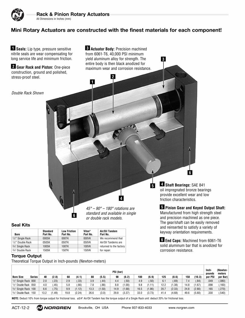
Shaft Bearings: SAE 841 oil impregnated bronze bearings provide excellent wear and low friction characteristics.
End Caps: Machined from 6061-T6solid aluminum bar that is anodized forcorrosion resistance.
Gear Rack and Piston: One-piece construction, ground and polished,stress-proof steel.
45° – 90° – 180° rotations are standard and available in single or double rack models.
Double Rack Shown
Seals: Lip type, pressure sensitivenitrile seals are wear compensating forlong service life and minimum friction.
Pinion Gear and Keyed Output Shaft:Manufactured from high strength steeland precision machined as one piece. The gear/shaft can be easily removed and reinserted to satisfy a variety ofkeyway orientation requirements.
Actuator Body: Precision machinedfrom 6061-T6, 40,000 PSI minimum yield aluminum alloy for strength. Theentire body is then black anodized formaximum wear and corrosion resistance.
Mini Rotary Actuators are constructed with the finest materials for each component!
1
2
3
5
4
6
21
3
5
4
6
NOTE: Deduct 10% from torque output for frictional loss. ø3/4" Air/Oil Tandem has the torque output of a Single Rack unit: deduct 20% for frictional loss.
Inch- (Newton-PSI (bar) pounds meters
Bore Size Series 40 (2.8) 60 (4.1) 80 (5.5) 90 (6.2) 100 (6.9) 125 (8.6) 150 (10.3) per PSI per Bar)1/2" Single Rack 000 2.0 (.23) 2.9 (.33) 3.9 (.44) 4.4 (.50) 4.9 (.50) 6.1 (.69) 7.4 (.84) .049 (.080)1/2" Double Rack 050 4.0 (.45) 5.8 (.66) 7.8 (.88) 8.8 (1.00) 9.8 (1.11) 12.2 (1.38) 14.8 (1.67) .098 (.160)3/4" Single Rack 100 6.6 (.75) 9.9 (1.12) 13.3 (1.50) 14.9 (1.68) 16.5 (1.86) 20.7 (2.33) 24.8 (2.80) .165 (.270)3/4" Double Rack 150 13.2 (1.49) 19.8 (2.24) 26.6 (3.0) 29.8 (3.37) 33.0 (3.73) 41.4 (4.68) 49.6 (5.60) .330 (.540)
Torque OutputTheoretical Torque Output in Inch-pounds (Newton-meters)
6
Seal Kits

Brookville, OH USA Phone 937-833-4033 www.norgren.com ACT-12-3
Rack & Pinion Rotary Actuators
Rotational Velocity
Operating SpecificationsOperating Temperature:
-20°F to 200°F (-29°C to 93°C) with Standard Nitrile Seals-20°F to 400°F (-29°C to 204°C) with Viton® Seals-20°F to 250°F (-29°C to 121°C) with Low Friction Seals
Operating Pressure:150 PSI (10 Bar)
Supply:Filtered compressed air to 150 PSI (10 Bar)
Angle of Rotation:45°, 90°, 180° StandardOther rotations available
Rotational Tolerance:-0° + 1/2°
Backlash Between Rack & Pinion:2 position units less than 1° of arc maximumNOTE: For 0° backlash at each end of rotation, specify a double rack actuator with rotation adjustments.
Lubrication:None requiredNorgren Rotary Actuators are rated for “no lube added”service. All internal components are lubricated at the time of assembly with a Teflon® based grease. Recommended fluid for air/oil tandem is petroleum basedhydraulic oil, non-foaming, non-detergentISO Viscosity grade of 46.Materials:End Caps: Black anodized 6061-T6 aluminum Body: 6061-T6 aluminum alloy, entirely black anodizedGear Rack: Ground and polished stress proof steelPinion Gear and Output Shaft: Manufactured as one piece
from high strength steel.Shaft Bearings: SAE 841 BronzeStandard Seals: Nitrile
Displacement forEach Degree Axial Load Radial Load Distance Basic Add for Doubleof Rotation Bearing Capacity Bearing Capacity Between Bearings Weight-180° Unit Output Shaft
Bore Size Inch3 (mm3) lbs (Kg) lbs (Kg) Inch (mm) lbs (Kg) lbs (Kg)1/2" Single Rack .0009 (15) 10 (4.54) 25 (11.35) .66 (17) .172 (.08) .031 (.01)1/2" Double Rack .0018 (30) 10 (4.54) 25 (11.35) .66 (17) 1.563 (.71) .031 (.01)3/4" Single Rack .0029 (48) 30 (13.62) 50 (22.70) .75 (19) 1.344 (.61) .063 (.03)3/4" Double Rack .0058 (95) 30 (13.62) 50 (22.70) .75 (19) 2.063 (.94) .063 (.03)
Displacement • Load Bearing Capacity • Unit WeightsDisplacement in cubic inches (mm3); Load Bearing Capacity in pounds force (kilograms);Bearing Distance in inches (mm); Unit Weights in pounds (kilograms)
Maximum rotational velocity of a rotary actuator is difficult to determine due to varying factors such as pressure, medium,flow and external loading. Excessive speeds in a given applicationcan create inertia loads whose shock values could prove detrimental to the actuator. Use of external stops, cushions, or other deceleration devices will ensure maximum performanceand actuator life. For calculating a moment of inertia, see page 26.
ACT-12-4 Brookville, OH USA Phone 937-833-4033 www.norgren.com
Rack & Pinion Rotary ActuatorsAll Dimensions in Inches (mm)
Mini Rotary Actuator Port LocationsSingle Rack Standard Double Rack Double Rack Integral
with No Rotation Adjustment with Rotation Adjustment Double Rack
Optional Features:• Port Locations• Rotation Adjustment• Viton® Seals for High Temperature
Mini Rotary Integral Air/Oil Tandem (ø3/4" Bore)
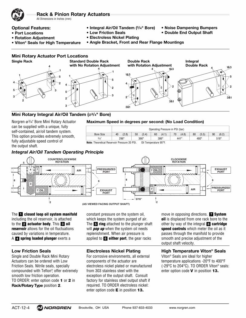
Integral Air/Oil Tandem Operating Principle
Norgren ø3/4" Bore Mini Rotary Actuatorcan be supplied with a unique, fully self-contained, air/oil tandem system.This option provides extremely smooth,fully adjustable speed control of the output shaft.
The closed loop oil system manifoldincluding the oil reservoir, is attached to the actuator body. This oilreservoir allows for the oil fluctuations caused by variations in temperature. A spring loaded plunger exerts a
move in opposing directions. Systemoil is displaced from one rack bore to theother by way of the integral cartridgespeed controls which meter the oil as itpasses through the manifold to providesmooth and precise adjustment of theoutput shaft velocity.
constant pressure on the system oil,which keeps the system purged of air. The ring attached to the plunger shaft will pop up when the system oil needs replenishment. When air pressure isapplied to either port, the gear racks
Operating Pressure in PSI (bar)
Bore Size 40 (2.8) 50 (3.4) 60 (4.1) 70 (4.8) 80 (5.5) 90 (6.2)3/4" 296° 366° 386° 441° 480° 518°
• Integral Air/Oil Tandem (3/4" Bore)• Low Friction Seals• Electroless Nickel Plating• Angle Bracket, Front and Rear Flange Mountings
• Noise Dampening Bumpers• Double End Output Shaft
CLOCKWISEROTATION
EXHAUSTPORT
COUNTERCLOCKWISEROTATION
4 PRESSURIZEDPORT
OIL
AIR
AIR
5
EXHAUSTPORT
PRESSURIZEDPORT
5/16''
(AS VIEWED FACING OUTPUT SHAFT)
3
OIL
88 66
7
7
7
7
2 2
1
1
2 3
4
5
6
7
8
Maximum Speed in degrees per second: (No Load Condition)
Note: Theoretical Reservoir Pressure 20 PSI. Oil Temperature 95°F.
High Temperature Viton® SealsViton® Seals are ideal for higher temperature applications -20°F to 400°F (-29°C to 204°C). TO ORDER Viton® seals:enter option code V in position 13.
Electroless Nickel PlatingFor corrosive environments, all externalcomponents of the actuator areelectroless nickel plated or manufacturedfrom 303 stainless steel with theexception of the output shaft. Consultfactory for stainless steel output shaft ifrequired. TO ORDER electroless nickel:enter option code E in position 13.
Low Friction SealsSingle and Double Rack Mini RotaryActuators can be ordered with LowFriction Seals. Nitrile seals, specially compounded with Teflon®, offer extremelysmooth low friction operation. TO ORDER: enter option code 1 or 2 inRack/Rotary Type position 2.

Brookville, OH USA Phone 937-833-4033 www.norgren.com ACT-12-5
Rack & Pinion Rotary ActuatorsAll Dimensions in Inches (mm)
Rotation AdjustmentLocated in the actuator end cap, each rotation adjustment provides up to 30° of angle reduction.
Front and Rear Flange Mountings R-80-100Flanges are universal andcan be used on both ø1/2"and ø3/4" Mini RotaryActuators. All flangemounts include mountinghardware. TO ORDER :enter option code 2 or 3in Mounting position 6.NOTE: Mini RotaryActuators come with standard 1/4" – 28threads/counterbore for#10 socket head capscrew, machined in thebody for direct mounting,if desired.
Angle BracketR-920-100The Angle Bracket can be used to mount any ø1/2" or ø3/4" Mini RotaryActuator perpendicular to the axis of a NorgrenSeries N twin rod cylinder (Section 4). Allbrackets include mountinghardware. TO ORDER: enter option code 5 inMounting position 6.NOTE: Mini RotaryActuators come with standard 1/4" – 28threads/counterbore for#10 socket head capscrew, machined in thebody for direct mounting,if desired.
Double EndOutput ShaftSingle and Double Rack Mini Rotary Actuators can be ordered with optional double end keyway outputshafts. TO ORDER: enteroption code B in OutputShaft position 5.
Noise DampeningBumpersA urethane insert isplaced in the gear rackpreventing metal tometal contact andproviding quiet operation.
A
A
CDE
F
B
IG H
J
AB
C D
øE øF
G
Optional DoubleEnd Output Shaft
Double Rack
Bore 1/2" 3/4"A .563 (14.29) .813 (20.64)
Optional DoubleEnd Output Shaft
Single Rack
Bore 1/2" 3/4"A 2.75 (70) 2.75 (70)B 2.125 (54) 2.125 (54)C 3.625 (92) 3.625 (92)D 4.25 (108) 4.25 (108)øE .281 (7) .281 (7)øF .281 (7) .281 (7)G .375 (10) .375 (10)
Bore 1/2" 3/4"A 2.00 (51) 2.00 (51)B .25 (6) .25 (6)C 3.00 (76) 3.00 (76)D 2.00 (51) 2.00 (51)E 1.25 (32) 1.25 (32)F .75 (19) .75 (19)G 2.50 (64) 2.50 (64)H 1.75 (44) 1.75 (44)I 1.00 (25) 1.00 (25)J .25 (6) .25 (6)

ACT-12-6 Brookville, OH USA Phone 937-833-4033 www.norgren.com
Rack & Pinion Rotary Actuators
� Single Rack and Pinion Mini Rotary Actuators are very compact.
� Theoretical torque from 2.0 to 24.8 inch-pounds (.23 to 2.80 Newton-meters).
� Rotation angles 45°, 90°, and 180° standard.
� Nitrile Noise Dampening Bumpers optional.
� Viton® Seals optional for higher temperatures.
� Optional Low Friction Seals.
� Body Mount or optional Angle Bracket, Front and Rear Flange Mountings.
Single Rack & Pinion Mini Rotary Actuator (ø1/2" & 3/4" Bores)
Cap B
Cap A
Port PositionsSingle Rack
Basic Dimensions Single Rack and Pinion Mini Rotary Actuator
H
2.00 (50.80)
1/4-28 Tapped ThruAlso Counterbore on Both Sides for #10 SocketHead Cap Screw for Mounting
A
1.00 (25.40)
E
G
.125 x .06 Deep(3.17 x 1.52)
P
D
Optional DoubleEnd Output Shaft
5 4
3
1
2
Cap A Cap B
Cap BCap A .88(22.35)
All Dimensions in Inches (mm)
21
0 0A A
Single Rack and Pinion Mini Rotary Actuator Order Information
Bore0 1/2" 1 3/4"
Rack/Rotary Type0 Single Rack Standard Seals 1 Single Rack Low Friction Seals
Multiple Position0 N/A
RotationA 45°B 90°C 180°X Special
Output ShaftA Single End Keyway Standard B Double End Keyway X Special
Mounting1 Standard2 Front Flange3 Rear Flange5 Angle BracketX Special
Port & LocationA Port Position 1*B Port Position 2C Port Position 3D Port Position 4F Port Position 5
BumperA No BumpersB End Cap AC End Cap BD All Caps
Rotation Adjustments1 No Adjustment 2 End Cap A3 End Cap B 4 End Caps A & BX Special
Options0 No Option E Electroless Nickel V Viton® Seals X Special (Specify)
Switches0 N/A
CushionsA N/A
Flow ControlsA N/A
3 4 5 6 7 8 9 10 11 12 13
See ACT-12-9 for complete instructionson how to order Mini Rotary Actuators.
*Standard Port Location
Bore A D E G H øK P1/2" Single Rack and Pinion 3.50 (89) 1.06 (27) 1.00 (25) 1.50 (38) .59 (15) .375 (9.53) 10-323/4" Single Rack and Pinion 4.88 (124) 1.25 (32) 1.25 (32) 2.00 (51) .69 (18) .500 (12.70) 1/8 NPT

Brookville, OH USA Phone 937-833-4033 www.norgren.com ACT-12-7
� Double Rack and Pinion Mini Rotary Actuators havedouble the theoretical torque of a Single RackRotary.
� Theoretical torque from 4.0 to 49.6 inch-pounds(.45 to 5.60 Newton-meters).
� Rotation angles 45°, 90°, and 180° standard.
� Nitrile Noise Dampening Bumpers optional.
� Viton® Seals optional for higher temperatures.
� Optional Low Friction Seals.
� Body Mount or optional Angle Bracket, Front and Rear Flange Mountings.
Rack & Pinion Rotary Actuators
Double Rack & Pinion Mini Rotary Actuator (ø1/2" & 3/4" Bores)
Basic DimensionsDouble Rack and PinionMini Rotary Actuator
2.00 (50.80)
1/4-28 Tapped ThruAlso Counterbore on Both Sides for #10 SocketHead Cap Screwfor Mounting
A
1.00 (25.40)
G
.125 x .06 Deep(3.17 x 1.52)
E
P
Cap B/DCap A/C
Optional DoubleEnd Output Shaft
.88(22.35) 1
3
5
D
H 52
2 4
4
Cap B/D
Cap A/C
Cap B/D
Cap A/C
Double Rack and Pinion Mini Rotary Actuator Order Information
21
0 0A A
Bore0 1/2" 1 3/4"
Rack/Rotary Type2 Double Rack Low Friction Seals 5 Double Rack Standard Seals
Multiple Position0 N/A
RotationA 45°B 90°C 180°X Special
Output ShaftA Single End Keyway Standard B Double End Keyway X Special
Mounting1 Standard2 Front Flange3 Rear Flange5 Angle BracketX Special
Port & LocationA Port Position 1*B Port Position 2C Port Position 3D Port Position 4F Port Position 5
BumperA No BumpersB End Cap AC End Cap BD All Caps
Rotation Adjustments1 No Adjustment 2 End Cap A3 End Cap B 4 End Caps A & B5 End Caps B & DX Special
Options0 No Option E Electroless Nickel V Viton® Seals X Special (Specify)
Switches0 N/A
CushionsA N/A
Flow ControlsA N/A
3 4 5 6 7 8 9 10 11 12 13
See ACT-12-9 for complete instructionson how to order Mini Rotary Actuators.
*Standard Port LocationNOTE: Port Position 5 is not available with Rotation Adjustment
Bore A D E G H øK P1/2" Double Rack and Pinion 3.75 (95) 1.06 (27) 1.00 (25) 2.50 (64) 1.25 (32) .375 (9.53) 1/8 NPT3/4" Double Rack and Pinion 4.75 (121) 1.25 (32) 1.25 (32) 3.00 (76) 1.50 (38) .500 (12.70) 1/8 NPT
Port Positions forDouble Rack(No Rotation Adjustment)
NOTE: With Rotation Adjustment, Port Position #1 includes Port Position #3Port Position #3 includes Port Position #1
Port Positions forDouble Rack with Rotation Adjustment
All Dimensions in Inches (mm)

ACT-12-8 Brookville, OH USA Phone 937-833-4033 www.norgren.com
Rack & Pinion Rotary Actuators
� Integral Air/Oil Tandem Double Rack and PinionMini Rotary Actuators have the sametheoretical torque of Single Rack Rotaries.
� Theoretical torque from 2.0 to 24.8 inch-pounds(.23 to 2.80 Newton-meters).
� Rotation angles 45°, 90°, and 180° standard.
� Nitrile Noise Dampening Bumpers optional.
� Viton® Seals optional for higher temperatures.
� Body Mount or optional Angle Bracket, Front andRear Flange Mountings.
Basic Dimensions Double Rack and Pinion Mini Rotary Actuator with Integral Air-Oil Tandem
Cap B/D
Standard Port Positions Integral Air/Oil TandemDouble Rack
NOTE: Port Position #1Includes Port Position #3
07
Integral Air/Oil Tandem Double Rack and Pinion Mini Rotary Actuator Order Information
21
1 0A A
Bore1 3/4"
Rack/Rotary Type7 Double Rack Integral A/O
Tandem Standard Seals
Multiple Position0 N/A
RotationA 45°B 90°C 180°X Special
Output ShaftA Single End Keyway Standard B Double End Keyway X Special
Mounting1 Standard2 Front Flange3 Rear Flange5 Angle BracketX Special
BumperA No BumpersB End Cap AC End Cap BD All Caps
Switches0 N/A
CushionsA N/A
Flow ControlsA N/A
3 4 5 6 7 8 9 10 11 12 13
See ACT-12-9 for complete instructionson how to order Mini Rotary Actuators.
Options0 No Option E Electroless Nickel V Viton® Seals X Special (Specify)
Port & LocationA Port Position 1 and 3*B Port Position 2D Port Position 4F Port Position 5
NOTE: Flow Controlsare standard on end caps A & C.
Rotation Adjustments1 No Adjustment 2 N/A3 End Cap B 4 N/A5 End Caps B & DX Special
*Standard Port Locations arePostions 1 and 3.
Bore A B D E G H øK P3/4" Double Rack with Air/Oil Tandem 5.75 (121) .3125 (8) 1.25 (32) 1.25 (32) 3.00 (76) 1.50 (38) .500 (12.70) .1/8 NPT
2.00 (50.80)
1/4-28 Tapped ThruAlso Counterbore on Both Sides for #10 SocketHead Cap Screw for Mounting
1.00 (25.40)
G
Optional DoubleEnd Output Shaft
.88(22.35) 1
3
5
D
H
A Cap B/D
B
.125 x .06 Deep(3.17 x 1.52)
E
P
52
2 4
4
Air/OilResevoir
All Dimensions in Inches (mm)

Brookville, OH USA Phone 937-833-4033 www.norgren.com ACT-12-9
Rack & Pinion Rotary Actuators
0 A
Cap A/C
A B
D C
Cap B/D
A
C
B
D
Cap B/DCap A
A B
Cap B
21
1 7 C B 2 B A 5 0 VA
Mini Rotary Actuator Order Information
Bore0 1/2" 1 3/4"
RotationA 45°B 90°C 180°X Special
Output ShaftA Single End Keyway Standard B Double End Keyway X Special
Mounting1 Standard2 Front Flange3 Rear Flange5 Angle BracketX Special
BumperA No BumpersB End Cap AC End Cap BD All Caps
Options0 No Option E Electroless Nickel V Viton® SealsX Special (Specify)
3 4 5 6 7 8 9 10 11 12 1321
Bore0 1/2" 1 3/4"
Rotation Adjustments1 No Adjustment 2 End Cap A3 End Cap B 4 End Caps A & B5 End Caps B & D X Special
3 4 5 6 7 8 9 10 11 12 13
Rack/Rotary Type0 Single Rack Standard Seals1 Single Rack Low Friction Seals2 Double Rack Low Friction Seals5 Double Rack Standard Seals7 Double Rack Integral A/O
Tandem Standard Seals(ø 3/4" Bore only in mini rotary)
Multiple Position ActuatorO 2 PositionX Special
EXAMPLE: Mini Rotary Actuator 3/4" Bore – Double Rack Integral Air/Oil Tandem Mini Rotary Actuator – 2 Position – 180° Rotation – Double End Keyway OutputShaft – Front Flange Mounting – Port Position 2 – No Bumpers – Rotation Adjustment End Caps B & D –Viton® Seals.
Single Rack Double Rack Integral Air/Oil Tandem Double Rack
Port PositionsSingle Rack
Port PositionsIntegral Double Rack
Port Positions Double Rack withoutRotation Adjustment
Port Positions Double Rack withRotation Adjustment
Port & LocationA Port Position 1*B Port Position 2C Port Position 3D Port Position 4F Port Position 5
Switches0 N/A
CushionsA N/A
Flow ControlsA N/A
*Standard Port Location

ACT-12-10 Brookville, OH USA Phone 937-833-4033 www.norgren.com
Rack & Pinion Rotary Actuators
Standard Low Friction Viton® Air/Oil TandemBore Part No. Part No. Part No. Part No.11/8" Single Rack 200SK 200TK 200VK We recommend11/8" Double Rack 250SK 250TK 250VK that Air/Oil 11/2" Single Rack 300SK 300TK 300VK Tandems are11/2" Double Rack 350SK 350TK 350VK returned to the2" Single Rack 400SK 400TK 400VK factory for repair.2" Double Rack 450SK 450TK 450VK21/2" Single Rack 500SK 500TK 500VK21/2" Double Rack 550SK 550TK 550VK
Seal Kits
Shaft Bearings: Sealed, single row ball bearings provide exceptional shaftstability with a low coefficient of friction.
10
Grease Fitting: Easy access for additional lubrication. Single rack located on top; double located on topand bottom.
12
1 2
53
6
8
8
7
4
11
10
9
End Caps: Machined from 6061-T6solid aluminum bar that is anodized forcorrosion resistance.
Tube: 6063-T832 aluminum alloywhich is ideally suited for air service. The tube is clear anodized on the O.D.and “hard anodic coated” on the I.D.which results in a smooth, file hard(60RC), corrosion and score resistantsurface finish.
Options not shown: Low Friction Seals, Cartridge Speed Controls,HighTemperature Viton® Seals, AdjustableCushions, Bumpers, Magnetic Pistonfor Position Sensing, Multi-PositionRotation Capabilities.
Rack: Ground and polished stress-proof steel.
Seals: Lip type, pressure sensitivenitrile seals are wear compensating for long service life and minimum friction.
Floating Pistons: Solid aluminum alloy, lightweight for low inertia, yetstrong. Provide excellent wear characteristics against the hard coated tube I.D.
Tie Rods: Stress-proof steel to maintain compression on the tube end seals.
Retainers: Aluminum plates are located on the front and rear of the actuator body to ensure positive retentionof the pinion/shaft/bearing assembly.
Pinion and Output Shaft:Manufactured from high strength steel for maximum strength and endurance. A keyed output shaft is standard withother shaft options available.
Actuator Body: Precision machinedfrom 6061-T6, 40,000 PSI minimum yield aluminum alloy for strength. Theentire body is then hard-anodized formaximum wear and corrosion resistance.
Rotary Actuators are constructed with the finest materials for each component!
Rotational Velocity
8
1
2
5
64
12Rotation Adjustment (optional): Up to
30° angle.7
119
3
45° – 90° – 180° – 270° – 360° rotationsare standard and available in single or double rack models. Other rotationsavailable up to 1080°.
Single Rack Shown
Maximum rotational velocity of a rotary actuator is difficult to determine due to varying factors such as pressure, medium,flow and external loading. Excessive speeds in a given applicationcan create inertia loads whose shock values could prove detrimental to the actuator. Use of external stops, cushions, or other deceleration devices will ensure maximum performanceand actuator life.

Brookville, OH USA Phone 937-833-4033 www.norgren.com ACT-12-11
Rack & Pinion Rotary ActuatorsAll Dimensions in Inches (mm)
Inch- (Newton-pounds meters
125 (8.6) 150 (10.3) 200 (13.8) 250 (17.2) 400 (27.6) per PSI per Bar)78 (8.8) 93 (17.5) 124 (10.5) 156 (17.6) 249 (28.1) .6 (.59)
155 (17.6) 187 (21.1) 249 (28.1) 311 (35.1) 498 (56.2) 1.2 (1.97)194 (21.9) 232 (26.2) 310 (35.0) 387 (43.7) 620 (70.0) 1.6 (2.62)387 (43.8) 465 (52.5) 620 (70.0) 774 (87.5) 1239 (140.0) 3.2 (5.24)550 (62.1) 660 (74.4) 879 (99.3) 1099 (124.1) 1758 (198.6) 4.4 (7.21)
1099 (124.1) 1319 (149.0) 1758 (198.6) 2198 (248.3) 3517 (397.2) 8.8 (14.41)860 (97.1) 1031 (116.5) 1375 (155.3) 1719 (194.1) 2750 (310.6) 6.9 (11.30)
1719 (194.1) 2062 (232.9) 2750 (310.6) 3437 (388.2) 5500 (621.2) 13.8 (22.60)
PSI (Bar)
Bore Size 40 (2.8) 60 (4.1) 80 (5.5) 90 (6.2) 100 (6.9)11/8" Single Rack 25 (2.8) 37 (4.2) 50 (5.6) 56 (6.3) 62 (7.0)11/8" Double Rack 50 (5.6) 75 (8.4) 100 (11.3) 112 (12.7) 124 (14.1)11/2" Single Rack 62 (7.0) 93 (10.4) 124 (14.0) 139 (15.7) 155 (17.5)11/2" Double Rack 124 (14.0) 186 (21.0) 248 (28.0) 279 (31.5) 310 (35.0)2" Single Rack 175 (19.9) 264 (29.8) 352 (39.7) 396 (44.7) 440 (49.7)2" Double Rack 352 (39.7) 528 (59.6) 703 (79.5) 791 (89.4) 879 (99.3)21/2" Single Rack 275 (31.0) 412 (46.6) 550 (62.1) 619 (69.9) 687 (77.7)21/2" Double Rack 550 (62.1) 825 (93.2) 1100 (124.2) 1237 (139.8) 1375 (155.3)
Torque OutputTheoretical Torque Output in Inch-pounds per PSI (Newton-meters per Bar)
Displacement Distancefor Each Degree Axial Load Radial Load Between Unit Weight Unit Weight Unit Weight Add for Doubleof Rotation Bearing Capacity Bearing Capacity Bearings 90° 180° 360° Output Shaft
Bore Size Inch3 (mm3) lbs (Kg) lbs (Kg) Inch (mm) lbs (Kg) lbs (Kg) lbs (Kg) lbs (Kg)11/8" Single Rack .0108 (177) 100 (45) 200 (91) 1.38 (35) 3.5 (1.59) 3.75 (1.70) 4.25 (1.93) .063 (.03)11/8" Double Rack .0216 (354) 100 (45) 200 (91) 1.38 (35) 6 (2.72) 7 (3.18) 8.5 (3.86) .063 (.03)11/2" Single Rack .0270 (443) 225 (102) 450 (204) 1.56 (40) 6.75 (3.06) 7.5 (3.41) 9 (4.09) .344 (.16)11/2" Double Rack .0540 (885) 225 (102) 450 (204) 1.56 (40) 10.5 (4.77) 12.75 (5.79) 17.25 (7.83) .344 (.16)2" Single Rack .0760 (1254) 500 (227) 1000 (454) 2.28 (58) 18 (8.17) 19.5 (8.85) 21 (9.53) .656 (.30)2" Double Rack .1520 (2491) 500 (227) 1000 (454) 2.28 (58) 22 (9.98) 24 (10.90) 27 (12.26) .656 (.30)21/2" Single Rack .1200 (1966) 500 (227) 1000 (454) 2.28 (58) 18.5 (8.40) 20 (9.08) 22 (9.99) .656 (.30)21/2" Double Rack .2400 (3933) 500 (227) 1000 (454) 2.28 (58) 22.5 (10.22) 24.5 (11.12) 27.5 (12.49) .656 (.30)
Displacement • Load Bearing Capacity • Unit WeightsDisplacement in cubic inches (mm3); Load Bearing Capacity in pounds force (kilograms);Bearing Distance in inches (mm); Unit Weights in pounds (kilograms)
Operating SpecificationsOperating Temperature:
-20° to 200°F (-29°C to 93°C) with Standard Nitrile Seals-20° to 400°F (-29°C to 204°C) with Viton® Seals-20° to 250°F (-29°C to 121°C) with Low Friction Seals
Operating Pressure:150 PSI (10 Bar)400 PSI (27.6 Bar) Hydraulic (non-shock)
Supply:Filtered compressed air to 150 PSI Petroleum based hydraulic fluid to 400 PSI
Angle of Rotation:45°, 90°, 180°, 270°, 360° StandardAny rotation up to 1080° can be supplied
Rotational Tolerance:-0° + 10°
Backlash Between Rack & Pinion:11/8" Bore 2 position units 1° of arc maximum11/2" – 21/2" Bore 2 position units 30 minutes of arc maximum
Lubrication:None requiredNorgren Rotary Actuators are rated for “no lube added”service. All internal components are lubricated at the time of assembly with a Teflon® based grease. Shouldadditional lubrication become necessary between theradial surface of the rack gear and the rack/pinion mesh area due to severe operating conditions, a grease fitting is provided.Materials:End Caps: Black anodized 6061-T6 aluminum Body: 6061-T6 aluminum alloy, entirely hard coat anodizedGear Rack: Ground and polished stress-proof steelPinion Gear and Output Shaft: Manufactured
from high-strength steel.Shaft Bearings: Sealed, single row ball bearingsStandard Seals: NitrileTube: 6063-T832 aluminum alloyTie Rods: Stress-proof steelFloating Pistons: Solid aluminum alloy
NOTE: Air/Oil Tandem and Multiple Position Rotary Actuators utilize a double rack configuration; however, the torque output of a SINGLE RACK unit apply. Deduct 10% fromtorque output for frictional loss. Deduct 20% for frictional loss on all Air/Oil Tandem Rotary Actuators.
ACT-12-12 Brookville, OH USA Phone 937-833-4033 www.norgren.com
Rack & Pinion Rotary Actuators
Optional Features:• Integral Air/Oil Tandem • Rotation Adjustment• Viton® Seals for High Temperature
Integral Air/Oil Tandem
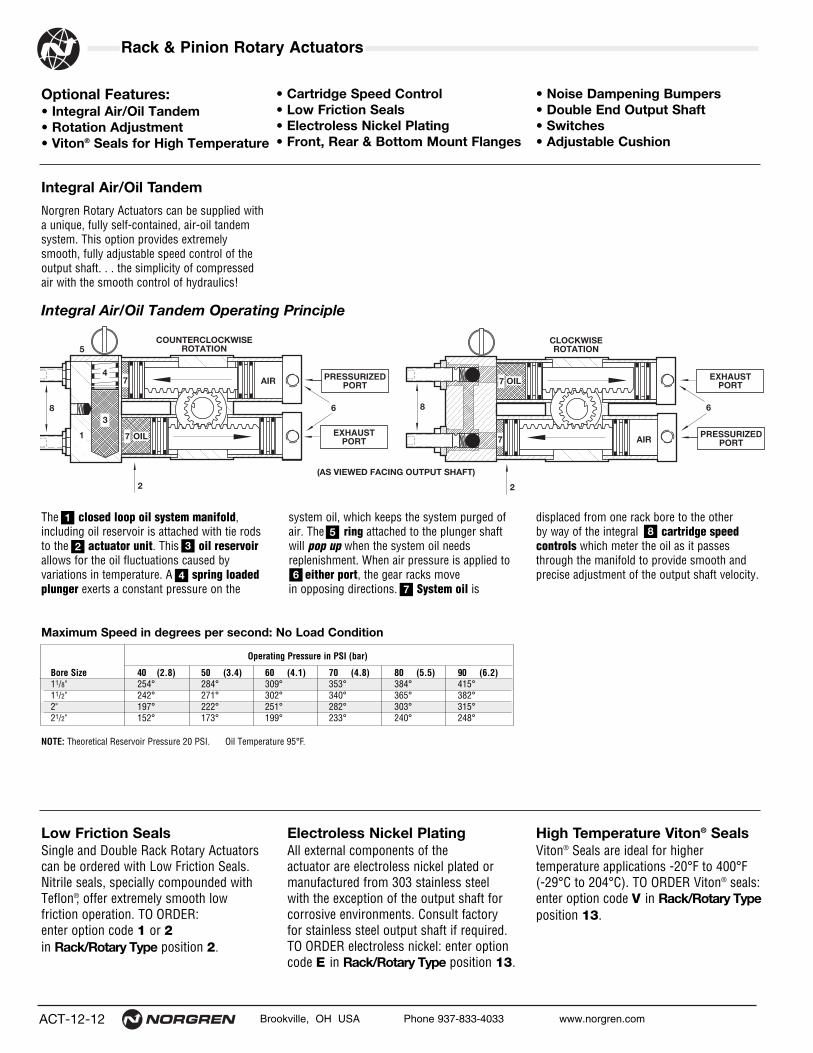
Integral Air/Oil Tandem Operating Principle
Norgren Rotary Actuators can be supplied witha unique, fully self-contained, air-oil tandemsystem. This option provides extremelysmooth, fully adjustable speed control of theoutput shaft. . . the simplicity of compressedair with the smooth control of hydraulics!
The closed loop oil system manifold,including oil reservoir is attached with tie rodsto the actuator unit. This oil reservoirallows for the oil fluctuations caused by variations in temperature. A spring loadedplunger exerts a constant pressure on the
displaced from one rack bore to the other by way of the integral cartridge speedcontrols which meter the oil as it passesthrough the manifold to provide smooth andprecise adjustment of the output shaft velocity.
system oil, which keeps the system purged ofair. The ring attached to the plunger shaft will pop up when the system oil needs replenishment. When air pressure is applied to
either port, the gear racks move in opposing directions. System oil is
High Temperature Viton® SealsViton® Seals are ideal for higher temperature applications -20°F to 400°F (-29°C to 204°C). TO ORDER Viton® seals:enter option code V in Rack/Rotary Typeposition 13.
Electroless Nickel PlatingAll external components of the actuator are electroless nickel plated ormanufactured from 303 stainless steelwith the exception of the output shaft forcorrosive environments. Consult factoryfor stainless steel output shaft if required.TO ORDER electroless nickel: enter optioncode E in Rack/Rotary Type position 13.
Low Friction SealsSingle and Double Rack Rotary Actuatorscan be ordered with Low Friction Seals.Nitrile seals, specially compounded withTeflon®, offer extremely smooth low friction operation. TO ORDER: enter option code 1 or 2in Rack/Rotary Type position 2.
• Cartridge Speed Control• Low Friction Seals• Electroless Nickel Plating• Front, Rear & Bottom Mount Flanges
• Noise Dampening Bumpers• Double End Output Shaft• Switches• Adjustable Cushion
OIL
CLOCKWISEROTATION
PRESSURIZEDPORT
PRESSURIZEDPORT
(AS VIEWED FACING OUTPUT SHAFT)
AIR
COUNTERCLOCKWISEROTATION
4
3
5
OIL AIR
88
2
1
2
6 6
7
7
7
7 EXHAUSTPORT
EXHAUSTPORT
1
2 3
4
5
67
8
Maximum Speed in degrees per second: No Load Condition
NOTE: Theoretical Reservoir Pressure 20 PSI. Oil Temperature 95°F.
Operating Pressure in PSI (bar)
Bore Size 40 (2.8) 50 (3.4) 60 (4.1) 70 (4.8) 80 (5.5) 90 (6.2)11/8" 254° 284° 309° 353° 384° 415°11/2" 242° 271° 302° 340° 365° 382°2" 197° 222° 251° 282° 303° 315°21/2" 152° 173° 199° 233° 240° 248°

Brookville, OH USA Phone 937-833-4033 www.norgren.com ACT-12-13
Rack & Pinion Rotary ActuatorsAll Dimensions in Inches (mm)
Bore 11/8" 11/2" 2" 21/2"A .687 (17.46) .938 (23.81) 1.187 (30.16) 1.187 (30.16)
Standard Air/OilTandemRotary unit is supplied withan Air/Oil Tank that requiresa 20 PSI pressure header.TO ORDER: enter optioncode 6 in Rack/RotaryType position 2.
Front and Rear Mounting Flanges TO ORDER: enter optioncode 2 or 3 in Rack/RotaryType position 6.
Noise DampeningBumperUrethane bumpers attached tothe actuator piston providesquiet operation by preventingmetal to metal contact.NOTE: Each bumper adds 1/4"to A dimension.
Cushioning The Cushioning PrincipleCushions permit the trappingof cylinder exhaust volumeprior to the completion of full rotation. This volume isthen metered through a finely tapered needle to deliver smooth, adjustabledeceleration of the rotaryactuator. NOTE: On 11/8"bores, add 1/2" to overalldimension for each cushion block. The design also provides exceptionally fast
out of cushion rotation reversal.
Cartridge Speed Controlø11/2" thru ø21/2" Bores only.NOTE: Cartridge SpeedControl & Cushion are notavailable on same end cap.
Check Valve FittingManifold
Cartridge Speed Control
.500(12.70)
.500(12.70)
Cushion Blocks
øFF øGG
AA
BB
CC DD
EE
5/16"
Rotation AdjustmentLocated in the actuator end cap, each rotation adjustment provides up to 30° of angle reduction. NOTE: Cushion & RotationAdjustment are not availableon the same end cap.
A
Adjustable Cushioning Flush, self locking adjustmentneedle allows fine cushionmetering. Cushion design features a unique, one piece,nitrile compound seal capturedwithin a groove machined toexacting tolerances.Thisallows linear and radial floatof the cushion seal, virtuallyeliminating problems associated with misalignment.
Cushion Design 11/8" Bore
Adjustment Needle
Cushion
BottomMounting Flanges TO ORDER: enter optioncode 4 in Rack/RotaryType position 6.
D
øE
A
C B
F
Bore 11/8" 11/2" 2" 21/2"Series 200 – 250 300 – 350 400 – 450 500 – 550Part R-942-225K R-942-03K R-942-04K R-942-04KA 4.250 (108) 5.000 (127) 5.000 (127) 5.000 (127)B 2.250 (57) 3.000 (76) 4.000 (102) 4.000 (102)C 1.625 (41) 2.375 (60) 3.375 (86) 3.375 (86)D 3.625 (92) 4.375 (111) 4.375 (111) 4.375 (111)øE .281 (7) .406 (10) .406 (10) .406 (10)F .375 (10) .437 (11) .437 (11) .437 (11)
Bore 11/8" 11/2" 2" 21/2"Series 200 – 250 300 – 350 400 – 450 500 – 550Part R-80-225K R-80-03K R-80-04K R-80-04KAA 4.812 (122) 5.875 (149) 8.625 (219) 8.625 (219)BB 4.062 (103) 5.125 (130) 7.625 (194) 7.625 (194)CC 1.500 (38) 1.500 (38) 2.000 (51) 2.000 (51)DD 2.250 (57) 2.750 (70) 4.000 (102) 4.000 (102)EE .250 (6) .375 (10) .437 (11) .437 (11)øFF .343 (9) .343 (9) .531 (13) .531 (13)øGG .562 (14) .937 (24) 1.312 (33) 1.312 (33)
Cushion Design 11/2" or 21/2" Bore

ACT-12-14 Brookville, OH USA Phone 937-833-4033 www.norgren.com
Rack & Pinion Rotary Actuators
� Single Rack and Pinion Rotary Actuators aredesigned for non-lube added service.
� Theoretical torque from 25 to 2750 inch-pounds(2.82 to 310.63 Newton-meters).
� Rotation angles 45°, 90°, 180°, 270° and 360° standard.
� Urethane Noise Dampening Bumpers optional.
� Viton® Seals optional for higher temperatures.
� Body Mount or optional Bottom, Front andRear Flange Mountings.
Single Rack & Pinion Rotary Actuator (ø11/8" to 21/2" Bores)
Single Rack and Pinion Rotary Actuator Order Information
Bore2 11/8" 3 11/2" 4 2" 5 21/2"
Rack/Rotary Type0 Single Rack Standard Seals 1 Single Rack Low Friction Seals X Special
Multiple Position Actuator0 N/A
RotationA 45°B 90°C 180°D 270°E 360°X Special
Output ShaftA Single End Keyway Standard B Double End Keyway C Hollow Internal Keyway D Cross Keyway E Preloaded Keyway X Special
Mounting1 Standard2 Front Flange3 Rear Flange4 Bottom FlangeX Special
Port Size & LocationPosition 1 2 3 4 5Standard A B* C D FOversized E G H J KSpecial X
BumperA No BumpersB End Cap AC End Cap BD All CapsX Special
Rotation Adjustments1 No Adjustment 2 End Cap A3 End Cap B 4 End Caps A & BX Special
Magnetic Option0 No Magnet M Standard Magnetic Piston in Position A & B
Options0 No Option E Electroless Nickel P Loaded Piston SealsV Viton® Seals X Special (Specify)
*Standard Port Size and Location.
CushionsNeedle Position 1 2 3 4 No Cushions AEnd Cap A B C D EEnd Cap B G H J KEnd Caps A & B N M P RSpecial X
Flow ControlsNeedle Position 1 2 3 4 No Flow Controls AEnd Cap A B C D EEnd Cap B G H J KEnd Caps A & B M N P RSpecial X
NOTE: Flow Controls must be 90° to Port Location. Flow controlsare Standard on all Air/ Oil Tandems. Standard Air/ Oil TandemFlow Controls are in end caps A & C in position #2. Integral Air/ OilTandem Flow Controls are in position #5.
NOTE: Cushions & Rotation Adjustment cannot be located insame end cap.
NOTE: See ACT-12-21 for information on switches.
NOTE: Standard rotationadjustments provide 30° ofangle reduction.
21 3 4 5 6 7 8 9 10 11 12 13
See ACT-12-20 for completeinstructions on how to order MiniRotary Actuators.

Brookville, OH USA Phone 937-833-4033 www.norgren.com ACT-12-15
Rack & Pinion Rotary ActuatorsAll Dimensions in Inches (mm)
A
B
NMounting HolesR Thds. T Deep (4)
M Keyway
FP
E
G
I
Q
H
D
L
F
SS
Optional Mounting HolesO Thds. U Deep (4)
C
Cap A Cap B
J
Remove the (4) Retainer Plate Screwsto use the Mounting Holeson either side of the body.
Retainer Plate
Dimension Degree Rotation 11/8" Bore Single Rack 11/2" Bore Single Rack 2" Bore Single Rack 21/2" Bore Single Rack
A 0°. 4.500 (114) 6.500 (165) 7.750 (197) 8.000 (203)45° 5.590 (142) 8.025 (204) 10.195 (259) 10.445 (265)90° 6.571 (167) 9.397 (239) 12.395 (315) 12.645 (321)180° 8.533 (217) 12.142 (308) 16.796 (427) 17.046 (433)270° 10.495 (267) 14.887 (378) 21.197 (538) 21.447 (545)360° 12.457 (316) 17.632 (448) 25.598 (650) 25.848 (657)
Add per ° .0218 (0.55) .0305 (0.77) .0489 (1.24) .0489 (1.24)AA .312 (7.92) .500 (12.70) .688 (17.48) 1.000 (25.40)B 2.250 (57) 2.750 (70) 4.000 (102) 4.000 (102)BB .093 (2.36) .125 (3.18) .187 (4.75) .187 (4.75)C .625 (16) 1.000 (25) 1.000 (25) 1.000 (25)CC .047 (1.19) .060 (1.52) .093 (2.36) .093 (2.36)D .875 (22) 1.750 (44) 2.031 (52) 2.031 (52)DD .234 (5.94) .250 (6.35) .500 (12.70) .500 (12.70)E 2.250 (57) 2.687 (68) 3.718 (94) 3.718 (94)EE .250 (6.35) .250 (6.35) .437 (11.10) .437 (11.10)F 1.500 (38) 2.000 (51) 2.500 (64) 3.000 (76)FF .500 (12.70) .750 (19.15) 1.125 (28.58) 1.125 (28.58)G 3.312 (84) 4.375 (111) 6.604 (168) 6.604 (168)H 1.656 (42) 2.187 (56) 3.302 (84) 3.302 (84)I 2.406 (61) 3.187 (81) 4.878 (124) 4.878 (124)J 1.000 (25) 1.500 (38) 1.500 (38) 1.500 (38)øK .500 (12.70) .875 (22.23) 1.125 (28.58) 1.125 (28.58)L .625 (16) 1.500 (38) 1.625 (67) 1.625 (67)M 1/8 x 1/16 3/16 x 3/32 1/4 x 1/8 1/4 x 1/8N 1.500 (38) 1.500 (38) 2.000 (51) 2.000 (51)O 1/4-20 1/4-20 7/16-14 7/16-14P 1/8 NPT 1/4 NPT 1/4 NPT 1/4 NPTQ .453 (12) .594 (15) .863 (22) .863 (22)R 1/4-20 5/16-24 1/2-20 1/2-20S .250 (6) .250 (6) .375 (10) .375 (10)T .250 (6) .313 (8) .500 (13) .500 (13)U .250 (6) .438 (11) .438 (11) .438 (11)
A
BB +.002–.000
CC
EE
FF
DD
+.002–.000
+.002–.000
+.001
Basic Dimensions Single Rack and Pinion Rotary Actuator
Shaft Options Internal Keyed HollowShaft can be utilized from either side andis flush with retaining plates.2" bore – 1.00" (25.4) hollow-optional21/2" bore – .688" (17.48) hollow-optional
Cross Keyed Shaft protrudes fromretainer EE dimension.
Flush with Retainer Surface
RetainerSurface

ACT-12-16 Brookville, OH USA Phone 937-833-4033 www.norgren.com
Rack & Pinion Rotary Actuators
� Double Rack and Pinion Rotary Actuators aredesigned for non-lube added service.
� Theoretical torque from 50 to 5500 inch-pounds(5.65 to 621.25 Newton-meters).
� Rotation angles 45°, 90°, 180°, 270° and 360° standard.
� Urethane Noise Dampening Bumpers optional.
� Viton® Seals optional for higher temperatures.
� Body Mount or optional Bottom, Front and Rear Flange Mountings.
Double Rack & Pinion Rotary Actuator (ø11/8" to 21/2" Bores)
Double Rack and Pinion Rotary Actuator Order Information
Bore2 11/8" 3 11/2" 4 2" 5 21/2"
Rack/Rotary Type2 Double Rack Low Friction Seals 5 Double Rack Standard Seals 6 Standard Air/Oil Tandem 7 Integral Air/Oil Tandem X Special
Multiple Position Actuator0 2 Position 3 3 Position 4 4 Position 5 5 Position X Special
RotationA 45°B 90°C 180°D 270°E 360°X Special
Output ShaftA Single End Keyway Standard B Double End Keyway C Hollow Internal Keyway D Cross Keyway E Preloaded Keyway X Special
Mounting1 Standard2 Front Flange3 Rear Flange4 Bottom FlangeX Special
Port Size & LocationPosition 1 2 3 4 5Standard A B* C D FOversized E G H J KSpecial X
BumperA No BumpersB End Cap AC End Cap BD All CapsX Special
Rotation Adjustments1 No Adjustment 2 End Cap A3 End Cap B 4 End Caps A & B5 End Caps B & D X Special
Magnetic Option0 No Magnet M Standard Magnetic Piston in Position A & B
Integral Air/Oil Tandems in Position B & D
Options0 No Option E Electroless Nickel P Loaded Piston SealsV Viton® SealsX Special (Specify)
*Standard Port Size and Location.
CushionsNeedle Position 1 2 3 4 No Cushions AEnd Cap A B C D EEnd Cap B G H J KEnd Caps A & B N M P RSpecial X
Flow ControlsNeedle Position 1 2 3 4 No Flow Controls AEnd Cap A B C D EEnd Cap B G H J KEnd Caps A & B M N P RSpecial X
NOTE: Flow Controls must be 90° to Port Location. Flow controlsare Standard on all Air/ Oil Tandems. Standard Air/ Oil TandemFlow Controls are in end caps A & C in position #2. Integral Air/ OilTandem Flow Controls are in position #5.
NOTE: Cushions & Rotation Adjustment cannot be located insame end cap.
NOTE: See page 21 for information on switches.
NOTE: Standard rotationadjustments provide 30° ofangle reduction.
21 3 4 5 6 7 8 9 10 11 12 13
See ACT-12-20 for completeinstructions on how to order MiniRotary Actuators.

Brookville, OH USA Phone 937-833-4033 www.norgren.com ACT-12-17
Rack & Pinion Rotary ActuatorsAll Dimensions in Inches (mm)
Basic Dimensions Double Rack and Pinion Rotary Actuator
A
B
M Keyway
F
P
C
Cap A Cap B
Cap DCap C N
G
I
H
F
J
SS
L
Q
Retainer Plate
D E
Mounting HolesR Thds.
T Deep (4)
Optional Mounting HolesO Thds. U Deep (4)
Remove the (4)Retainer Plate Screws
to use the Mounting Holeson either side of the body.
A
BB +.002–.000
CC
EE
FF
DD
+.002–.000
+.002–.000
+.001Shaft Options Internal Keyed HollowShaft can be utilized from either side and isflush with retaining plates.2" bore – 1.00" (25.4) hollow-optional21/2" bore – .688" (17.48) hollow-optional
Cross Keyed Shaft protrudes fromretainer EE dimension.
Flush with Retainer Surface
RetainerSurface
Dimension Degree Rotation 11/8" Bore Double Rack 11/2" Bore Double Rack 2" Bore Double Rack 21/2" Bore Double Rack
A 0°. 4.500 (114) 6.500 (165) 7.750 (197) 8.000 (203)45° 5.590 (142) 8.025 (204) 10.195 (259) 10.445 (265)90° 6.571 (167) 9.397 (239) 12.395 (315) 12.645 (321)180° 8.533 (217) 12.142 (308) 16.796 (427) 17.046 (433)270° 10.495 (267) 14.887 (378) 21.197 (538) 21.447 (545)360° 12.457 (316) 17.632 (448) 25.598 (650) 25.848 (657)
Add per ° .0218 (0.55) .0305 (0.77) .0489 (1.24) .0489 (1.24)AA .312 (7.92) .500 (12.70) .688 (17.48) 1.000 (25.40)B 2.250 (57) 2.750 (70) 4.000 (102) 4.000 (102)BB .093 (2.36) .125 (3.18) .187 (4.75) .187 (4.75)C .625 (16) 1.000 (25) 1.000 (25) 1.000 (25)CC .047 (1.19) .060 (1.52) .093 (2.36) .093 (2.36)D .875 (22) 1.750 (44) 2.031 (52) 2.031 (52)DD .234 (5.94) .250 (6.35) .500 (12.70) .500 (12.70)E 2.250 (57) 2.687 (68) 3.718 (94) 3.718 (94)EE .250 (6.35) .250 (6.35) .437 (11.10) .437 (11.10)F 1.500 (38) 2.000 (51) 2.500 (64) 3.000 (76)FF .500 (12.70) .750 (19.15) 1.125 (28.58) 1.125 (28.58)G 3.312 (84) 4.375 (111) 6.604 (168) 6.604 (168)H 1.656 (42) 2.187 (56) 3.302 (84) 3.302 (84)I 2.406 (61) 3.187 (81) 4.878 (124) 4.878 (124)J 1.000 (25) 1.500 (38) 1.500 (38) 1.500 (38)øK .500 (12.70) .875 (22.23) 1.125 (28.58) 1.125 (28.58)L .625 (16) 1.500 (38) 1.625 (67) 1.625 (67)M 1/8 x 1/16 3/16 x 3/32 1/4 x 1/8 1/4 x 1/8N 1.500 (38) 1.500 (38) 2.000 (51) 2.000 (51)O 1/4-20 1/4-20 7/16-14 7/16-14P 1/8 NPT 1/4 NPT 1/4 NPT 1/4 NPTQ .453 (12) .594 (15) .863 (22) .863 (22)R 1/4-20 5/16-24 1/2-20 1/2-20S .250 (6) .250 (6) .375 (10) .375 (10)T .250 (6) .313 (8) .500 (13) .500 (13)U .250 (6) .438 (11) .438 (11) .438 (11)

ACT-12-18 Brookville, OH USA Phone 937-833-4033 www.norgren.com
Rack & Pinion Rotary Actuators
Standard Air/Oil Tandem is supplied with an Air/Oil Tank.
� Air/Oil Tank should have 20 PSI pressure header.
� Integral Air/Oil Tandem is fully self-contained.
� The simplicity of compressed air with the smooth control of hydraulics.
� Provides extremely smooth, fully adjustable speedcontrol of the actuator output shaft.
Rotary Actuator Air/Oil Tank TankBore Size Model Number Bore Size AA B C D K
11/8" AOT-225X2 11/8" 1.500 (38) 3.125 (79) 2.750 (70) .750 (19) 1/8" NPT11/2" AOT-225X3 11/8" 1.500 (38) 4.125 (105) 3.750 (95) .750 (19) 1/8" NPT2" AOT-225X4 11/8" 1.500 (38) 5.125 (130) 4.750 (121) .750 (19) 1/8" NPT
21/2" AOT-225X5 11/8" 1.500 (38) 6.125 (156) 5.750 (146) .750 (19) 1/8" NPT
Dimension Degree Rotation 11/8" Standard 11/2" Standard 2" Standard 21/2" Standard
A 0°. 5.125 (130) 7.500 (191) 8.750 (222) 9.000 (229)45° 6.215 (158) 9.025 (292) 11.195 (284) 11.445 (291)90° 7.196 (183) 10.397 (264) 13.395 (340) 13.645 (347)180° 9.158 (233) 13.142 (333) 17.796 (452) 18.046 (458)270° 11.121 (282) 15.887 (404) 22.197 (563) 22.447 (570)360° 13.082 (332) 18.632 (473) 26.598 (676) 26.848 (682)
Dimension Degree Rotation 11/8" Integral 11/2" Integral 2" Integral 21/2" IntegralA 0°. 6.125 (156) 8.000 (203) 9.500 (241) 10.000 (254)
45° 7.215 (183) 9.525 (242) 11.945 (303) 12.445 (316)90° 8.196 (208) 10.897 (277) 14.145 (359) 14.645 (372)180° 10.158 (258) 13.642 (347) 18.546 (471) 19.046 (484)270° 12.120 (308) 16.387 (416) 22.947 (583) 23.447 (596)360° 14.082 (358) 19.132 (486) 27.348 (695) 27.848 (707)
Add per ° .0218 (1) .0305 (1) .0489 (1) .0489 (1)
A
Cap D
Cap B
Supplied w/Steel Tubes Aluminum Tube w/OptionalMagnetic Pistons provided
at Caps B & D
4" max.
.173 1-1/8 Bore
.312 1-1/2–2-1/2 Bore
A
Cap A Cap B
Cap DCap C
Manifold
AA
D
BCK NPTPort
1/8" NPTOil Filler Port
located on top
Tank Mounting Holes are .203 drilled thru .328 Counterbore for #10 Socket Head Cap Screw
Standard Air/Oil Tandem
Length Dimensions for Air/Oil Tandems
Dimensions for Air/Oil Tanks
Integral Air/Oil TandemRefer to ACT-12-12 for Operating Principle.

Brookville, OH USA Phone 937-833-4033 www.norgren.com ACT-12-19
Rack & Pinion Rotary ActuatorsAll Dimensions in Inches (mm)
Dimension 11/8" 11/2" 2" 21/2"AA 3.625 (92) 5.375 (54) 6.000 (152) 6.250 (159)BB 2.250 (57) 3.250 (83) 3.875 (98) 4.000 (102)CC .011 (.28) .015 (.38) .024 (.61) .024 (.61)
Multiple Position Rack and Pinion RotaryActuators are capable of producing 3, 4,or 5 predetermined output shaft positions.Each intermediate stop position specifiedis mechanically locked and therefore notadjustable. Use of optional rotation
4-Position Rotary Actuator
R° = Rotation of base unit in degrees (Positions 1 and 4)
S° = Change in rotation of base unit (Position 2)
T° = Change in rotation of base unit (Position 3)
5-Position Rotary Actuator
TotalR° = Rotation of base unit in degrees
S° = Change in rotation of base unit (Position 2)
T° = Change in rotation of base unit (Position 3)
Z° = Change in rotation of base unit (Position 4)
adjustments at the full clockwise andcounterclockwise positions will provideup to 30° of angular reduction at eachend.
The alternate pressurizing and exhausting
POSITION #290°
POSITION #4270°
POSITION #5270°
POSITION #10°
POSITION #267.5° POSITION #3
125°
POSITION #4192.5°
POSITION #3180°
POSITION #10°
POSITION #290°
POSITION #3180°
POSITION #10°
(R° + T°) CC + AA
(R° + S°) CC + AA (R° + Z°) CC + AA
(R° + T°) CC + AA
(R° x CC) + BB (R° + CC) + BB
5 Position Rotary Actuator
(R° + S°) CC + AA
(R° + T°) CC + AA
(R° x CC) + B (R° + CC) + BB
AA
4 Position Rotary Actuator
3 Position Rotary Actuator
Cap A1
Cap D1
Cap B1
Cap A1
Cap D
Cap B
Cap B
Cap DCap C
Cap A
Cap A
Cap C
Cap A
Cap C Cap D
Cap B
Cap C1
Cap C1
of various actuator ports will determinewhich output shaft position is obtained.This can be accomplished with the use ofsimple, directional control valving andallows output shaft positioning in virtuallyANY desired sequence.
Output Shaft Pressurize Port(s)Position Number in Cap(s) Exhaust
1 C All other ports2 A1 & C1 All other ports3 A & B All other ports4 B1 & D1 All other ports5 D All other ports
Output Shaft Pressurize Port(s)Position Number in Cap(s)) Exhaust
1 C All other ports2 A & B All other ports3 D All other ports
Output Shaft Pressurize Port(s)Position Number in Cap(s) Exhaust
1 C All other ports2 A1 & C1 All other ports3 A & B All other ports4 D All other ports
NOTE: The 3-position actuator dimensions are the same as a standard 2-position unit. Keyway in position shown is at midpoint of rotation.

ACT-12-20 Brookville, OH USA Phone 937-833-4033 www.norgren.com
Rack & Pinion Rotary Actuators
BC
Rack and Pinion Rotary Actuator Order Information
Bore2 11/8" 3 11/2" 4 2" 5 21/2"
Rack/Rotary Type0 Single Rack Standard Seals 1 Single Rack Low Friction Seals 2 Double Rack Low Friction Seals 5 Double Rack Standard Seals 6 Standard Air/Oil Tandem 7 Integral Air/Oil Tandem X Special
Multiple Position Actuator0 2 Position 3 3 Position 4 4 Position 5 5 Position X Special
RotationA 45°B 90°C 180°D 270°E 360°X Special Output Shaft
A Single End Keyway Standard B Double End Keyway C Hollow Internal Keyway D Cross Keyway E Preloaded Keyway X Special
Mounting1 Standard2 Front Flange3 Rear Flange4 Bottom FlangeX Special
Port LocationPosition 1 2 3 4 5Standard A B* C D FOversized E G H J KSpecial X
BumperA No BumpersB End Cap AC End Cap BD All CapsX Special
Rotation Adjustments1 No Adjustment 2 End Cap A3 End Cap B 4 End Caps A & B5 End Caps B & D X Special
Options0 No Option E Electroless Nickel P O-Ring Loaded Piston SealsV Viton® SealsX Special (Specify)
*Standard Port Size and Location.
CushionsNeedle Position 1 2 3 4 No Cushions AEnd Cap A B C D EEnd Cap B G H J KEnd Caps A & B N M P RSpecial X
Flow ControlsNeedle Position 1 2 3 4 No Flow Controls AEnd Cap A B C D EEnd Cap B G H J KEnd Caps A & B M N P RSpecial X
NOTE: Flow Controls must be 90° to Port Location. Flow controlsare Standard on all Air/ Oil Tandems. Standard Air/ Oil TandemFlow Controls are in end caps A & C in position #2. Integral Air/ OilTandem Flow Controls are in position #5.
NOTE: Cushions & Rotation Adjustment cannot be located insame end cap.
NOTE: Standard rotation adjustmentsprovide 30° of angle reduction.
21
2 5 0 1 B B A D 3 M E
3 4 5 6 7 8 9 10 11 12 13
52 4
1
3
Cap A Cap B
Cap C Cap D
Port position availablein Positions 1-5Cushion Needle
position available inPositions 1-4
End Cap Designations(As viewed facing
output shaft)
Magnetic Option0 No Magnet M Standard Magnetic Piston in Position A & B
Integral Air/Oil Tandems in Position B & D
NOTE: See ACT-12-21 for information on switches.
EXAMPLE: 11/8" Bore – Double Rack with Standard Seals –2 Position Rotary Actuator – 180° Rotation – Double EndKeyway – Standard Mounting – Standard Port Located at Position 2 – Cushion Position 1 in End Cap A – No Flow Controls – Bumpers on All Caps – End Cap BRotation Adjustments – Standard Magnetic Piston Option –Electroless Nickel Plated.

Brookville, OH USA Phone 937-833-4033 www.norgren.com ACT-12-21
Rack & Pinion Rotary Actuators
• Magnetically operated, non-contact sensing system.
• Consists of a magnet in the piston, and a sensing switch clamped on the actuator tie rod.
• One or more switches may be mounted to provide an indication of piston position or to control or initiate any sequence function.
• Adjustable mounting brackets are standard, and allow switches to be securely positioned anywhere along the range of piston travel.
• LED indicator light facilitates installation and troubleshooting.
In order to obtain optimum performance and longlife, magnetically operated limit switches should not be subjected to: (1) strong magnetic fields, (2) extreme temperature, and (3) excessive ferrousfiling or chip buildup.Improper wiring may damage or destroy the switch.The wiring diagram, along with the listed power ratings, must be carefully observed before connecting power to the switch.Lower power switches are designed for signalingelectronic circuits. Do not use on relay loads or with incandescent bulbs. Resistive loads only.
1.3 (32)
.7(17.7)
.53 (13.5)
.43 (10.8)
1.1 (27.4)
Switch & Mounting BracketDimensions
Wiring Diagrams WHT
Supply20v Max
Load
Center of Sensing Area
0.45+
_
BRNWHT
BRN
Load
Supply -24 VDC
0.10
Center of Sensing Area
+
_
GRN
WHT
Supply6-24 VDC
Load
Center of Sensing Area
BRN
0.10+
_
GRN
Specifications *Metal Oxide Varsitor Surge Suppression. NOTE: All CS8 Series Switches are supplied with 9 foot leads.
CS8-2 Series
Application Recommendationsand PrecautionsTo provide maximum reliability:1. Always stay within the specifications and power
rating limitations of the unit installed.2. Primary and control circuit wiring should not be
mixed in the same conduit. Motors will produce high pulses that will be introduced into the control wiring if the wiring is carried in the same conduit.
3. Never connect the switch without a load present. The switch will be destroyed.
4. Some electrical loads may be capacitive. Capacitive loading may occur due to distributed capacity in cable runs over 25 feet. Use switch Model CS7-24 whenever capacitive loading may occur. Refer to NCA-60 catalog.
Switch Model CS8-2-04 Reed CS8-2-31 Solid State CS8-2-32 Solid State
Bore Sizes 11/8" thru 21/2" 11/8" thru 21/2" 11/8" thru 21/2"Switch Type Reed Switch Solid State & Light, Solid State & Light,
*MOV & Light Sourcing PNP Sinking NPNFunction SPST Normally Open Normally Open Normally OpenSwitching Voltage 5-120 VDC/VAC 6-24 VDC 6-24 VDC
50/60 HzSwitching Current .5 Amp Max .5 Amp Max .5 Amp Max
.005 Amp MinSwitching Power 10 VA 12 Watts Max 12 Watts MaxMax Voltage Drop 3.5 Volts .5 Volts .5 VoltsMagnetic Sensitivity 85 Gauss 85 Gauss 85 GaussEnclosure Classification NEMA 6 & CSA Approved NEMA 6 & CSA Approved NEMA 6 & CSA ApprovedTemperature Range -22°F to +176°F -22°F to +176°F -22°F to +176°F
All Dimensions in Inches (mm)

ACT-12-22 Brookville, OH USA Phone 937-833-4033 www.norgren.com
Rack & Pinion Rotary Actuators
A Rotary Table Flange is attached to the body of a Rotary Actuator tocreate a mounting surface for the rotarytable assembly. This assembly consists of a Table Housing machined from6061-T6 aluminum alloy. This housing is specifically designed to incorporate two individual Thrust Bearings, each sandwiched between two steel
Surface Washers. These bearingsaccept axial and radial loads that areapplied to the rotary table assembly.
The Hub, also machined from 6061-T6aluminum alloy, is centrally positioned
elements expand and contract radially,locking the hub to the output shaft. In this locked condition, the output shaft and hub act as a single unit, allowing therotational forces (torque) of the outputshaft to be directly transmitted to the hub.
The keyless design of the coupler allowsinfinite positioning of the tapered holeslocated in the hub. These holes enableeither vertical or horizontal mounting of a Series N Non-Rotating Rod Cylinder (Section 4).
over the actuator Output Shaft. A Wear Band located on the hubenhances load carrying capability. The Slotted Locking Ring retainsthe hub and thrust bearings to the table housing.
Attachment of the hub to the actuator output shaft is accomplished by a
Coupler. The coupler is a simple, keyless design consisting of an inner collet-like element, an outer sleeve setand a Hex Nut. The inner and outerelements have matching opposing tapers.As the hex nut is tightened, the coupler
12
3
4
5
6
1
2
3 4
5
6
7
8
9
10
11
7
8
9
10
11

Brookville, OH USA Phone 937-833-4033 www.norgren.com ACT-12-23
Rack & Pinion Rotary ActuatorsAll Dimensions in Inches (mm)
H TAP (4)
F
G
A B
D
EACROSSFLATS
C
H TAP (8)
K
*A
B
C
G
F J EACROSSFLATS
*A
F
G
EACROSSFLATS
B
D
C
H TAP (4)
D
MM-1 MM-2 MM-3
MM-1 Rotary TableUse with ø3/4" or ø11/8" Bore Rotary Actuator.Accepts 11/8" Bore Series N (Section 4). WithRotary Table Plate MM-80-03, accepts 11/2"Bore Series N (Section 4). NOTE: When interfacing with ø3/4" Bore MiniRotary Actuator, a Double Rack model is recommended.
Optional Rotary Table PlateLarger than standard rear flange mounting patterns for the MM-1 and MM-2 RotaryTables are available by the simple interface of the optional Rotary Table Plate.
When using optional rotary table plate:MM-1 accepts Series N 11/2" BoreMM-2 accepts Series N 2" or 21/2" BoreMM-3 accepts Series N 2" or 21/2" BoreRefer to Section 4.
MM-2 Rotary TableUse with ø11/2" Bore Rotary Actuator.Accepts 11/2" Bore Series N (Section 4).With Rotary Table Plate MM-80-04, accepts 2" or 21/2" Bore Series N (Section 4).
MM-3 Rotary TableUse with ø2" or ø21/2" Bore Rotary Actuator.(Rotary Table Plate MM-80-04, comes standard). Accepts 11/2" Bore Series N (Section 4) without Rotary Table Plate MM-80-04. Accepts 2" or 21/2" Bore Series N (Section 4) with Rotary Table Plate MM-80-04.
Rotary Table Dimensions
Coupler Hex Size: 7/8"
*Add 9/32" when used on a ø3/4" Mini Rotary
Coupler Hex Size: 1-1/2" Coupler Hex Size: 2"
D G
E
F
B
C TAP
A
Rotary Table A B C D E F G H J KMM-1 1.625 (41) 1.344 (34) 3.438 (87) 2.688 (68) 2.500 (64) 2.000 (51) 1.000 (25) 10 – 32 – –MM-2 2.807 (71) 1.328 (34) 5.125 (130) 4.125 (108) 4.355 (111) 2.750 (70) 1.428 (36) 1/4 – 28 – –MM-3 4.117 (105) 2.638 (67) 5.125 (130) 5.500 (140) 4.355 (111) 3.375 (86) 1.838 (47) 5/16 – 24 2.192 (56) 3.875 (98)
Rotary Table Use withPlate Part # Rotary Table A B C D E F GMM-80-03 MM-1 4.000 (102) .250 (6) 1/4 – 28 2.750 (70) 1.428 (36) – –MM-80-04 MM-2 5.500 (140) .375 (10) 5/16 – 24 3.375 (86) 1.838 (47) 3.875 (98) 2.192 (56)MM-80-04 MM-3 5.500 (140) .375 (10) 5/16 – 24 3.375 (86) 1.838 (47) 3.875 (98) 2.192 (56)

ACT-12-24 Brookville, OH USA Phone 937-833-4033 www.norgren.com
Rack & Pinion Rotary Actuators
Rotary Actuator Rotary Table Series N Rotary Table Series NBore Size Part No. Bore Size Plate Part No. Bore Size*3/4" or 11/8" + MM-1 + 11/8" = OR + MM-80-03 + 11/2" =11/2" + MM-2 + 11/2" = OR + MM-80-04 + 2" or 21/2" =2" or 21/2" + **MM-3 + 11/2" = OR + MM-80-04 + 2" or 21/2" =
Series N Cylinder Series NBore Size Mounting Plate Bore Size11/8" + MM-225-00A + 11/8" =11/2" + MM-225-00A + 11/8" =11/2" + MM-003-00A + 11/2" =2" + MM-003-00A + 11/2" =2" + MM-004-00A + 2" =21/2" + MM-004-00A + 2" =21/2" + MM-005-00A + 21/2" =
Modular Mini Rotary Mini RotarySeries N Adaptor Actuator Angle ActuatorBore Size Plate Bore Size Bracket Bore Size11/8" + NB-172-225K + 1/2" or 3/4"= OR + R-920-100 + 1/2" or 3/4" =11/2" + NB-172-03K + 1/2" or 3/4"= OR + R-920-100 + 1/2" or 3/4" =2" + NB-172-04K + 1/2" or 3/4"= OR + R-920-100 + 1/2" or 3/4" =21/2" + NB-172-05K + 1/2" or 3/4"= OR + R-920-100 + 1/2" or 3/4" =
Rotary Rotary Cylinder Series NActuator Table Mounting Plate Bore Size*3/4" or 11/8" + MM-1 + MM-225-00A + 11/8" =11/2" + MM-2 + MM-003-00A + 11/2" =11/2" + MM-2 + MM-004-00A + 2" =11/2" + MM-2 + MM-005-00A + 21/2" =2" + MM-3 + MM-003-00A + 11/2" =2" + MM-3 + MM-004-00A + 2" =2" + MM-3 + MM-005-00A + 21/2" =21/2" + MM-3 + MM-003-00A + 11/2" =21/2" + MM-3 + MM-004-00A + 2" =21/2" + MM-3 + MM-005-00A + 21/2" =
Norgren Motion Modules may be assembled in a number of single or multi-axis configurations to provide awide range of linear and rotary movements. The selection guide shown
below is intended to graphically assist inthe interface of appropriate MOTIONMODULES and ACCESSORIES required toaccomplish the specific configurations.
MOTION MODULES afford such totaldesign flexibility that the selection guidehas been limited to only the more basicMOTION MODULE assemblies.
*When interfacing MM-1 Rotary Table with 3/4" bore Mini Rotary Actuator, a double rack model is recommended.**Rotary Table MM-3 includes Rotary Table Plate No. MM-80-04. Remove Rotary Table MM-80-04 to use 11/2" Series N.

Brookville, OH USA Phone 937-833-4033 www.norgren.com ACT-12-25
Rack & Pinion Rotary ActuatorsAll Dimensions in Inches (mm)
Rotary Actuator Torque Output Series N Extend & Retract Forcesin Inch-pounds per PSI (Newton-meters per Bar) in Pounds (Newtons)
Input Pressure 3/4" Bore 1-1/8" Bore 1-1/8" Bore 1-1/2" BorePSI (bar) Single Double Single Double Extend Retract Extend Retract30 (2) 4.9 (8.03) 9.9 (16.21) 18.7 (30.62) 37.4 (61.25) 29.9 (132.00) 26.9 (119.65) 53.1 (236.19) 46.5 (206.83)40 (3) 6.6 (10.80) 13.2 (21.62) 24.9 (40.78) 49.8 (81.56) 39.8 (177.03) 35.9 (159.68) 70.8 (314.92) 61.8 (274.89)50 (3.5) 8.3 (13.59) 16.5 (27.02) 31.1 (50.93) 62.3 (102.04) 49.8 (221.51) 44.9 (199.72) 88.5 (393.65) 77.3 (343.83)60 (4) 9.9 (16.21) 19.8 (32.43) 37.3 (61.09) 74.6 (122.18) 59.7 (265.55) 53.8 (239.30) 106.2 (472.38) 92.8 (412.77)70 (5) 11.6 (18.99) 23.1 (37.83) 43.6 (71.41) 87.1 (142.66) 69.7 (310.03) 62.8 (279.33) 123.9 (551.11) 108.5 (482.61)80 (6) 13.3 (21.78) 26.6 (43.57) 49.8 (81.56) 99.6 (163.12) 79.6 (354.06) 71.8 (319.37) 141.6 (629.84) 123.7 (550.22)90 (6.2) 14.9 (24.40) 29.8 (48.80) 56.0 (91.72) 112.0 (183.44) 89.6 (398.54) 80.7 (358.95) 159.3 (708.57) 139.5 (620.50)
100 (7) 16.5 (27.02) 33.0 (54.05) 62.2 (101.87) 124.4 (203.75) 99.5 (442.48) 89.7 (398.99) 177.0 (787.30) 154.6 (687.60)125 (8.6) 20.7 (33.90) 41.4 (67.81) 77.7 (127.26) 155.4 (254.52) 124.4 (553.33) 112.1 (498.62) 221.3 (984.34) 193.3 (859.80)150 (10) 24.8 (40.62) 49.6 (81.24) 93.3 (152.81) 186.6 (305.62) 149.2 (663.64) 134.6 (598.70) 265.5 (1180.94) 231.9 (1031.49)
Rotary Table Model MM-1
Rotary Table Weights & Hex Nut Installation Torques How to Order Rotary Tables
Consolidated Motion Module Torque Output and Force Data
Rotary Table Model MM-2
Rotary Table Model MM-3
Rotary Actuator Torque Output Series N Extend & Retract Forcesin Inch-pounds per PSI (Newton-meters per Bar) in Pounds (Newtons)
Input Pressure 1-1/2" Bore 1-1/2" Bore 2" Bore 2-1/2" BorePSI (bar) Single Double Extend Retract Extend Retract Extend Retract30 (2) 46.5 (76.16) 93.0 (152.32) 53.1 (236.19) 46.5 (206.83) 94.2 (482.61) 82.5 (366.96) 147.3 (655.19) 129.0 (573.79)40 (3) 62.0 (101.55) 124.0 (203.09) 70.8 (314.92) 61.8 (274.89) 125.6 (558.67) 109.9 (488.35) 196.4 (873.59) 171.8 (764.16)50 (3.5) 77.5 (126.93) 155.0 (253.87) 88.5 (393.65) 77.3 (343.83) 157.0 (698.34) 137.4 (611.16) 245.5 (1091.98) 214.8 (955.30)60 (4) 92.9 (152.16) 185.8 (304.31) 106.2 (472.38) 92.8 (412.77) 188.4 (838.35) 164.9 (733.47) 294.6 (1310.38) 257.8 (1146.69)70 (5) 108.5 (177.71) 217.0 (355.41) 123.9 (551.11) 108.5 (482.61) 219.8 (977.67) 192.5 (856.24) 343.7 (1525.97) 301.0 (1338.85)80 (6) 123.9 (202.93) 247.8 (405.86) 141.6 (629.84) 123.7 (550.22) 251.2 (1117.34) 219.8 (977.67) 392.8 (1747.17) 343.7 (1528.78)90 (6.2) 139.4 (228.31) 278.8 (456.63) 159.3 (708.57) 139.5 (620.50) 282.6 (1257.00) 247.5 (1100.88) 441.9 (1965.57) 387.0 (1721.38)
100 (7) 154.9 (253.70) 309.8 (507.40) 177.0 (787.30) 154.6 (687.60) 314.0 (1396.67) 274.8 (1222.31) 491.0 (2183.96) 429.6 (1910.86)125 (8.6) 193.6 (317.08) 387.2 (634.17) 221.3 (984.34) 193.3 (859.80) 392.5 (1754.84) 343.5 (1527.89) 613.8 (2730.18) 537.0 (2388.58)150 (10) 232.3 (380.47) 464.6 (760.94) 265.5 (1180.94) 231.9 (1031.49) 471.0 (2095.00) 412.2 (1833.10) 736.5 (3275.95) 644.4 (2866.29)
NOTE: All Rotary Actuator torque outputs and Series N Cylinder forces listed above are theoretical. Deduct 10% from these torques and forces to allow for friction loss in actual application.Deduct 20% on all Air/Oil Tandem Rotary Actuators. Air/Oil Tandem and Multiple Position Rotary Actuators utilize a double rack configuration; however, the torque outputs of a single rack unit apply.
Rotary Rotary Table Weight Hex Nut InstallationTable Pounds (Kilograms) Torque in Foot-Pounds (Newton-meters)MM-1 1.125 (0.511) 30 ft. lbs. (40.66)MM-2 5.5625 (2.525) 160 ft. lbs. (216.87)MM-3 7.875 (3.575) 240 ft. lbs. (325.31)
Order When InterfacingRotary with this sizeTable Rotary ActuatorMM-1 *3/4" or 1-1/8"MM-2 1-1/2"MM-3 2" or 2-1/2"
NOTE: All Rotary Tables are supplied with a torque bar to simplify coupler installation.NOTE: *When interfacing MM-1 Rotary Table with 3/4" BoreMini Rotary Actuator, a double rack model isrecommended.
Rotary Actuator Torque Output Series N Extend & Retract Forcesin Inch-pounds per PSI (Newton-meters per Bar) in Pounds (Newtons)
Input Pressure 2" Bore 2-1/2" Bore 2" Bore 2-1/2" BorePSI (bar) Single Double Single Double Extend Retract Extend Retract30 (2) 131.9 (216.03) 263.8 (432.06) 206.3 (337.88) 412.6 (675.77) 94.2 (482.61) 82.5 (366.96) 147.3 (655.19) 129.0 (573.79)40 (3) 175.8 (287.93) 351.6 (575.86) 275.0 (450.41) 550.0 (900.81) 125.6 (558.67) 109.9 (488.35) 196.4 (873.59) 171.8 (764.16)50 (3.5) 219.8 (360.00) 439.5 (719.83) 343.8 (563.09) 687.6 (1126.17) 157.0 (698.34) 137.4 (611.15) 245.5 (1091.98) 214.8 (955.30)60 (4) 263.8 (431.73) 527.6 (864.12) 412.4 (675.45) 824.8 (1350.89) 188.4 (838.35) 164.9 (733.47) 294.6 (1310.38) 257.8 (1146.69)70 (5) 307.7 (503.96) 615.3 (1007.76) 481.3 (708.29) 962.6 (1576.59) 219.8 (977.67) 192.5 (856.24) 343.7 (1525.97) 301.0 (1338.85)80 (6) 351.7 (576.03) 703.4 (1152.06) 549.9 (900.65) 1099.8 (1801.29) 251.2 (1117.34) 219.8 (977.67) 392.8 (1747.17) 343.7 (1528.78)90 (6.2) 395.6 (647.92) 791.2 (1259.86) 618.7 (1013.33) 1237.4 (2026.66) 282.6 (1257.00) 247.5 (1100.88) 441.9 (1965.51) 387.0 (1721.38)
100 (7) 439.6 (720.00) 879.2 (1439.99) 687.4 (1125.85) 1374.8 (2251.70) 314.0 (1396.67) 274.8 (1222.31) 491.0 (2183.96) 429.6 (1910.86)125 (8.6) 549.5 (899.99) 1099.0 (1799.99) 859.3 (1407.40) 1718.6 (2814.79) 392.5 (1754.84) 343.5 (1527.89) 613.8 (2730.18) 537.0 (2388.58)150 (10) 659.4 (1079.99) 1318.8 (2159.98) 1031.1 (1688.78) 2062.2 (3377.56) 471.0 (2095.00) 412.2 (1833.10) 736.5 (3275.95) 644.4 (2866.29)

ACT-12-26 Brookville, OH USA Phone 937-833-4033 www.norgren.com
Rack & Pinion Rotary Actuators
Maximum Kinetic Energy Rating for Model Based on Configuration (in.-lb.)Bore Non-Cushioned Cushioned11/8"" 0.5 511/2" 2.0 202" 4.0 4021/2" 7.0 70
Moments of Inertia
W1 4l 12 + w2 W2 4l 22 + w 2J = — x ———— + — x —————
g 12 g 12W1 l 1 2 W2 l22J = —— x —— + —— x ——g 3 g 3
W l 2J = —— x ——
g 1 2
W 2r2J = —— x ——
g 5W r2
J = —— x ——g 2
WJ = —— x r2g
W r2J = —— x ——
g 4Thin DiskEnd mounted on center
Sphere Mountedon center
Thin DiskMountedon center
Thin Rectangular PlateMounted on center
Load off Center(Torque)
Thin Rectangular Plate Thin Rod
KE = Jω2
2
ω = 0.035 x Angle traveled (degrees)Rotation time (seconds)
where:KE = Kinetic Energy (in-lb)J = Rotational mass moment of inertia (in-lb-sec2)
(Dependent on physical size of object and weight)ω = Peak Velocity (rad/sec) (Assuming twice average velocity)W = Weight of load (lb) g = Acceleration due to gravity = 386.4 in/sec2
r = Radius of gyration (in)l = length from point of rotationw = width

Brookville, OH USA Phone 937-833-4033 www.norgren.com ACT-12-27
Rack & Pinion Rotary Actuators
Screw Clamping RotationAutomation Transfer
Valve Turning Mixer Material Handling
Load and Unload Machine Intermittent FeedConstant Tension
Turn or OscillateTurnover or Dumping
Toggle Push or Clamp
Lift or Rotate
Conveyor Turn or Stop
Index or Position
