rack monitor 450/550/570 installation and quick … · netbotz® rack monitor 450/550/570...
TRANSCRIPT
NetBotz®
Rack Monitor 450/550/570
Installation and Quick Configuration ManualNBRK0450
NBRK0550
NBRK0570
990-3291GPublication Date: February, 2017
To get the latest features, update the firmware before using.Go to apc.com or dcimsupport.apc.com to download updates for this product.

Schneider Electric Legal DisclaimerThe information presented in this manual is not warranted by Schneider Electric to be authoritative, error free, or complete. This publication is not meant to be a substitute for a detailed operational and site specific development plan. Therefore, Schneider Electric assumes no liability for damages, violations of codes, improper installation, system failures, or any other problems that could arise based on the use of this Publication.
The information contained in this Publication is provided as is and has been prepared solely for the purpose of evaluating data center design and construction. This Publication has been compiled in good faith by Schneider Electric. However, no representation is made or warranty given, either express or implied, as to the completeness or accuracy of the information this Publication contains.
IN NO EVENT SHALL SCHNEIDER ELECTRIC, OR ANY PARENT, AFFILIATE OR SUBSIDIARY COMPANY OF SCHNEIDER ELECTRIC OR THEIR RESPECTIVE OFFICERS, DIRECTORS, OR EMPLOYEES BE LIABLE FOR ANY DIRECT, INDIRECT, CONSEQUENTIAL, PUNITIVE, SPECIAL, OR INCIDENTAL DAMAGES (INCLUDING, WITHOUT LIMITATION, DAMAGES FOR LOSS OF BUSINESS, CONTRACT, REVENUE, DATA, INFORMATION, OR BUSINESS INTERRUPTION) RESULTING FROM, ARISING OUT, OR IN CONNECTION WITH THE USE OF, OR INABILITY TO USE THIS PUBLICATION OR THE CONTENT, EVEN IF SCHNEIDER ELECTRIC HAS BEEN EXPRESSLY ADVISED OF THE POSSIBILITY OF SUCH DAMAGES. SCHNEIDER ELECTRIC RESERVES THE RIGHT TO MAKE CHANGES OR UPDATES WITH RESPECT TO OR IN THE CONTENT OF THE PUBLICATION OR THE FORMAT THEREOF AT ANY TIME WITHOUT NOTICE.
Copyright, intellectual, and all other proprietary rights in the content (including but not limited to software, audio, video, text, and photographs) rests with Schneider Electric or its licensors. All rights in the content not expressly granted herein are reserved. No rights of any kind are licensed or assigned or shall otherwise pass to persons accessing this information.
This Publication shall not be for resale in whole or in part.
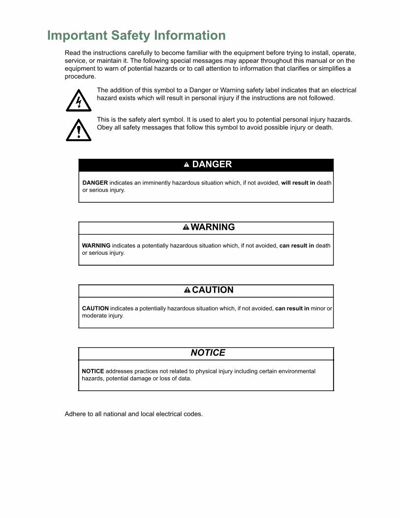
Important Safety InformationRead the instructions carefully to become familiar with the equipment before trying to install, operate, service, or maintain it. The following special messages may appear throughout this manual or on the equipment to warn of potential hazards or to call attention to information that clarifies or simplifies a procedure.
The addition of this symbol to a Danger or Warning safety label indicates that an electrical hazard exists which will result in personal injury if the instructions are not followed.
This is the safety alert symbol. It is used to alert you to potential personal injury hazards. Obey all safety messages that follow this symbol to avoid possible injury or death.
Adhere to all national and local electrical codes.
DANGER
DANGER indicates an imminently hazardous situation which, if not avoided, will result in death or serious injury.
WARNING
WARNING indicates a potentially hazardous situation which, if not avoided, can result in death or serious injury.
CAUTION
CAUTION indicates a potentially hazardous situation which, if not avoided, can result in minor or moderate injury.
NOTICE
NOTICE addresses practices not related to physical injury including certain environmental hazards, potential damage or loss of data.

Table of Contents
Important Safety Information . . . . . . . . . . . . . . . . . . . . . . . . . . . . . . . . . . . . . . . . . . . . . . . i
Introduction ............................................................................................................1Product Description . . . . . . . . . . . . . . . . . . . . . . . . . . . . . . . . . . . . . . . . . . . . . . . . . . . . . .1Document Overview . . . . . . . . . . . . . . . . . . . . . . . . . . . . . . . . . . . . . . . . . . . . . . . . . . . . . .1Related Documents . . . . . . . . . . . . . . . . . . . . . . . . . . . . . . . . . . . . . . . . . . . . . . . . . . . . . .1Additional Options . . . . . . . . . . . . . . . . . . . . . . . . . . . . . . . . . . . . . . . . . . . . . . . . . . . . . . .1StruxureWare-certified . . . . . . . . . . . . . . . . . . . . . . . . . . . . . . . . . . . . . . . . . . . . . . . . . . . .2
Physical Description...............................................................................................3Inventory ................................................................................................................5Installation..............................................................................................................6
Install the Appliance . . . . . . . . . . . . . . . . . . . . . . . . . . . . . . . . . . . . . . . . . . . . . . . . . . . . . .6Rack-mount installation . . . . . . . . . . . . . . . . . . . . . . . . . . . . . . . . . . . . . . . . . . . .7Power cord and network cable connections . . . . . . . . . . . . . . . . . . . . . . . . . . . . .8
Connect Sensors to Sensor Ports . . . . . . . . . . . . . . . . . . . . . . . . . . . . . . . . . . . . . . . . . . .9Connect an Alarm Beacon and Other Optional Devices . . . . . . . . . . . . . . . . . . . . . . . . .10Connect Sensors and Sensor Pods to A-Link Ports. . . . . . . . . . . . . . . . . . . . . . . . . . . . .11
Initial Configuration ..............................................................................................12Overview. . . . . . . . . . . . . . . . . . . . . . . . . . . . . . . . . . . . . . . . . . . . . . . . . . . . . . . . . . . . . .12
Obtain network settings using DHCP . . . . . . . . . . . . . . . . . . . . . . . . . . . . . . . . .12Install the Advanced View . . . . . . . . . . . . . . . . . . . . . . . . . . . . . . . . . . . . . . . . . .12Configure network settings using a terminal emulator . . . . . . . . . . . . . . . . . . . .12Install a wireless network device . . . . . . . . . . . . . . . . . . . . . . . . . . . . . . . . . . . .13
The NetBotz Configuration Wizard . . . . . . . . . . . . . . . . . . . . . . . . . . . . . . . . . . . . . . . . . .14Access an Appliance . . . . . . . . . . . . . . . . . . . . . . . . . . . . . . . . . . . . . . . . . . . . . . . . . . . .14
Overview . . . . . . . . . . . . . . . . . . . . . . . . . . . . . . . . . . . . . . . . . . . . . . . . . . . . . . .14Administrator account user ID and password . . . . . . . . . . . . . . . . . . . . . . . . . . .14Root account user ID and password . . . . . . . . . . . . . . . . . . . . . . . . . . . . . . . . . .15Lost password recovery . . . . . . . . . . . . . . . . . . . . . . . . . . . . . . . . . . . . . . . . . . .15Web Client . . . . . . . . . . . . . . . . . . . . . . . . . . . . . . . . . . . . . . . . . . . . . . . . . . . . .16Advanced View . . . . . . . . . . . . . . . . . . . . . . . . . . . . . . . . . . . . . . . . . . . . . . . . . .16
NetBotz Quick Configuration . . . . . . . . . . . . . . . . . . . . . . . . . . . . . . . . . . . . . . . . . . . . . .17Configure appliance settings . . . . . . . . . . . . . . . . . . . . . . . . . . . . . . . . . . . . . . .17Configure alert actions . . . . . . . . . . . . . . . . . . . . . . . . . . . . . . . . . . . . . . . . . . . .18
Upgrade Options..................................................................................................19Software Feature Upgrades . . . . . . . . . . . . . . . . . . . . . . . . . . . . . . . . . . . . . . . . . . . . . . .19Hardware Upgrades . . . . . . . . . . . . . . . . . . . . . . . . . . . . . . . . . . . . . . . . . . . . . . . . . . . . .19
Add pods to your appliance . . . . . . . . . . . . . . . . . . . . . . . . . . . . . . . . . . . . . . . .20Connect a wireless sensor network . . . . . . . . . . . . . . . . . . . . . . . . . . . . . . . . . .22Connect a USB modem . . . . . . . . . . . . . . . . . . . . . . . . . . . . . . . . . . . . . . . . . . .24Connect a USB digital I/O device . . . . . . . . . . . . . . . . . . . . . . . . . . . . . . . . . . . .24Connect an APC Switched Rack PDU . . . . . . . . . . . . . . . . . . . . . . . . . . . . . . . .25Connect external sensors . . . . . . . . . . . . . . . . . . . . . . . . . . . . . . . . . . . . . . . . . .25
NetBotz Rack Monitor 450/550/ i
Disposal............................................................................................................... 26Clean the NetBotz 450/550/570 .......................................................................... 26Specifications ...................................................................................................... 27
Sensor Specifications . . . . . . . . . . . . . . . . . . . . . . . . . . . . . . . . . . . . . . . . . . . . . . . . . . . 28
Warranty .............................................................................................................. 29Two-Year Factory Warranty . . . . . . . . . . . . . . . . . . . . . . . . . . . . . . . . . . . . . . . . . . . . . . 29
Terms of warranty . . . . . . . . . . . . . . . . . . . . . . . . . . . . . . . . . . . . . . . . . . . . . . . 29Non-transferable warranty . . . . . . . . . . . . . . . . . . . . . . . . . . . . . . . . . . . . . . . . 29Exclusions . . . . . . . . . . . . . . . . . . . . . . . . . . . . . . . . . . . . . . . . . . . . . . . . . . . . . 29Warranty claims . . . . . . . . . . . . . . . . . . . . . . . . . . . . . . . . . . . . . . . . . . . . . . . . 30
NetBotz Rack Monitor 450/550/ii
Introduction
Product DescriptionThe Schneider Electric NetBotz® Rack Monitor 570, Rack Monitor 550 or Rack Monitor 450 functions as the central hardware appliance for a NetBotz security and environmental monitoring system. The rack-mountable appliance includes multiple ports for connecting APC environmental sensors and other third-party sensors. The appliances include additional ports that provide power to or allow control over other devices. With a NetBotz 570, 550, or 450, you can increase the space monitored. With a NetBotz 570 or 550, you can add up to twelve NetBotz sensor pods. With a NetBotz 450, you can add up to two NetBotz sensor pods.
Document OverviewThe NetBotz Rack Monitor 450/550/570 Installation and Quick Configuration Manual describes how to install a NetBotz Rack Monitor 450, 550, or 570, how to connect devices to the appliances, and how to configure network settings. After performing the configuration procedures in this manual, you can access your system through its software interface, perform additional configuration tasks, and begin monitoring the environment.
Related DocumentsUnless otherwise noted, the following documentation is available on the applicable product page on the APC web site, www.apc.com or on dcimsupport.apc.com.To quickly find a product page on apc.com, enter the product name or part number in the Search field.
NetBotz Appliance User’s Guide – Includes all details for using, managing, and configuring a NetBotz system with one of the following appliances: NetBotz Room Monitor 355 (NBWL0355, NBWL0356), NetBotz Rack Monitor 450 (NBRK0450), NetBotz Room Monitor 455 (NBWL0455, NBWL0456), NetBotz Rack Monitor 550 (NBRK0550), or NetBotz Rack Monitor 570 (NBRK0570).
1NetBotz Rack Monitor 450/550/570 Installation and Quick Con-
Additional OptionsThe following options are available for the appliance. For more information about any of the options, contact your APC representative or the distributor from whom you purchased your APC product.
• NetBotz Camera Pod 160 (NBPD0160)• NetBotz Rack Sensor Pod 150 (NBPD0150)• NetBotz Room Sensor Pod 155 (NBPD0155)• Temperature Sensor (AP9335T)• Temperature/Humidity Sensor (AP9335TH)• Temperature Sensor with Digital Display (AP9520T)• Temperature/Humidity Sensor with Digital Display (AP9520TH)• Alarm Beacon (AP9324)• NetBotz Spot Fluid Sensor (NBES0301)• NetBotz Door Switch Sensor for Rooms or Third Party Racks (NBES0302)• NetBotz Door Switch Sensor for APC Racks (NBES0303)• NetBotz Dry Contact Cable (NBES0304)• NetBotz 0-5 V Sensor Cable (NBES0305)• NetBotz Vibration Sensor (NBES0306)• NetBotz Smoke Sensor (NBES0307)• NetBotz Rope Leak Sensor (NBES0308)• NetBotz Rope Leak Extension (NBES0309)• NetBotz Particle Sensor PS100 (NBES0201)• NetBotz USB-to-Serial Cable (NBAC0226)• Power Supply 100-230 VAC/24 VDC (AP9505i)• NetBotz 4-20mA Sensor Pod (NBPD0129)• NetBotz CCTV Adapter 120 with USB Cable (NBPD0123)• NetBotz Sensor Pod 120 (NBPD0122)• NetBotz Camera Pod 120 (NBPD0121)• NetBotz Rack Access Pod 170 (NBPD0170) (for NBRK0550 and NBRK0570 only)• NetBotz Rack Access Electronic Handle (NBHN0170) (for NBRK0550 and NBRK0570
only)NBHN017BHN0171• NetBotz Wireless Sensor Pod 180 (NBPD180)• NetBotz USB Coordinator & Router (NBWC100U)• NetBotz Wireless Temperature Sensor (NBWS100T and NBWS100H)
StruxureWare-certifiedThis product is certified for use in Schneider Electric StruxureWare® systems.
NetBotz Rack Monitor 450/550/570 Installation and Quick Con-2
Physical Description
Item Description
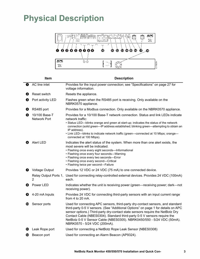
AC line inlet Provides for the input power connection; see “Specifications” on page 27 for voltage information.
Reset switch Resets the appliance.
Port activity LED Flashes green when the RS485 port is receiving. Only available on the NBRK0570 appliance.
RS485 port Provides for a Modbus connection. Only available on the NBRK0570 appliance.
10/100 Base-T Network Port
Provides for a 10/100 Base-T network connection. Status and link LEDs indicate network traffic:• Status LED—blinks orange and green at start-up; indicates the status of the network
connection (solid green—IP address established; blinking green—attempting to obtain an IP address).
• Link LED—blinks to indicate network traffic (green—connected at 10 Mbps; orange—connected at 100 Mbps).
Alert LED Indicates the alert status of the system. When more than one alert exists, the most severe will be indicated.• Flashing once every eight seconds—Informational• Flashing once every four seconds—Warning• Flashing once every two seconds—Error• Flashing once every second—Critical• Flashing twice per second—Failure
Voltage Output Provides 12 VDC or 24 VDC (75 mA) to one connected device.
Relay Output Ports 1, 2
Used for connecting relay-controlled external devices. Provides 24 VDC (100mA) each.
Power LED Indicates whether the unit is receiving power (green—receiving power; dark—not receiving power).
4-20 mA Inputs Provides 24 VDC for connecting third-party sensors with an input current range from 4 to 20 mA.
Sensor ports Used for connecting APC sensors, third-party dry-contact sensors, and standard third-party 0-5 V sensors. (See “Additional Options” on page 1 for details on APC sensor options.) Third-party dry-contact state sensors require the NetBotz Dry Contact Cable (NBES0304). Standard third-party 0-5 V sensors require the NetBotz 0-5 V Sensor Cable (NBES0305). NBRK0450/550 - 5/24 VDC (50mA). NBRK0570 - 5/24 VDC (200mA).
Leak Rope port Used for connecting a NetBotz Rope Leak Sensor (NBES0308)
Beacon port Used for connecting an Alarm Beacon (AP9324).
3NetBotz Rack Monitor 450/550/570 Installation and Quick Con-
A-Link port Used for cascading NetBotz sensor pods and temperature and humidity sensors with digital displays. Provides communications and power to the connected devices over standard CAT-5 cabling with straight-through wiring. For details, see “Connect Sensors and Sensor Pods to A-Link Ports” on page 11.
Alert LED Same as item 4 above.
Power LED Indicates whether the unit is receiving power (green—receiving power; dark—not receiving power).
Console Port Used to connect a console to the appliance. Enable the USB-to-serial converter support (FTDI) in your operating system.
USB Type A ports (2 or 4)
Used to connect USB devices to the appliance. The NBRK0550 and NBRK0450 have two USB ports, while the NBRK0570 has four.
Exhaust fan Exhausts hot air from the NBRK0570. Not present on the NBRK550 or NBRK450.
Item Description
NetBotz Rack Monitor 450/550/570 Installation and Quick Con-4
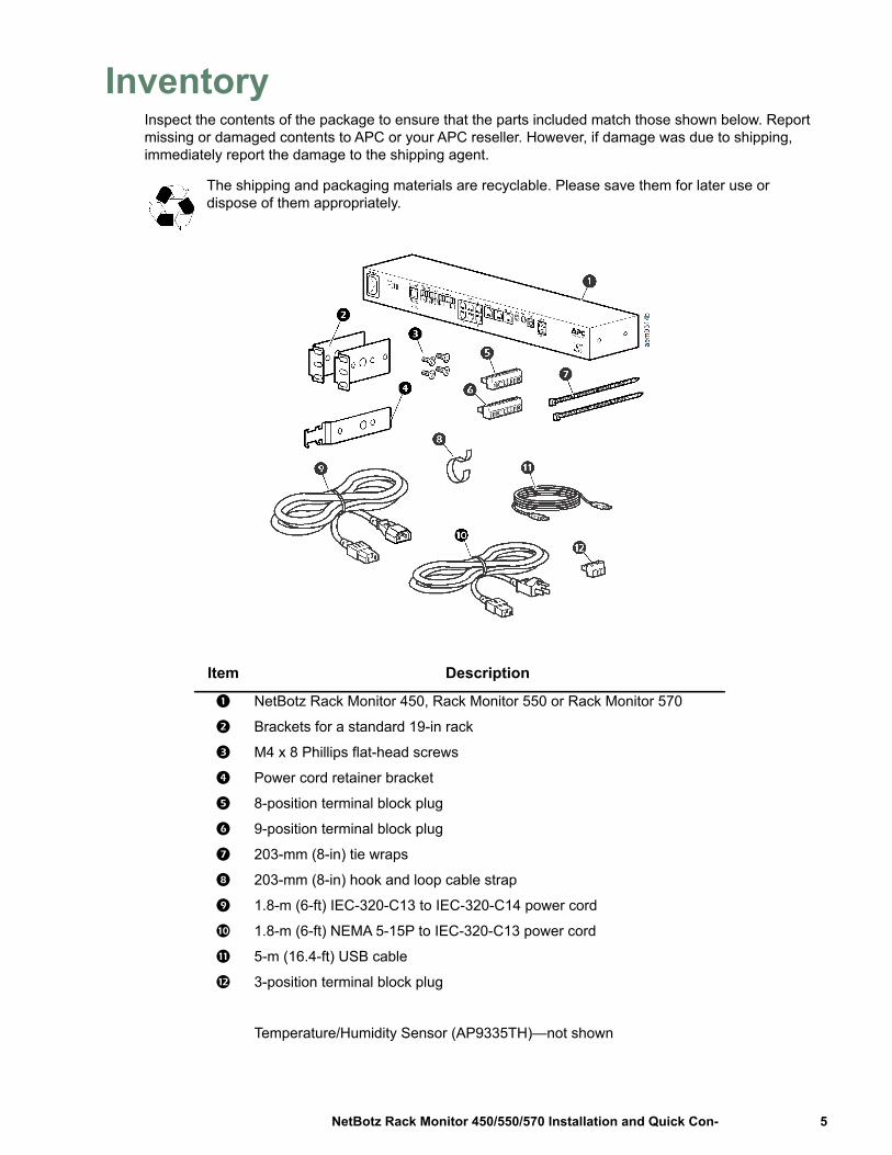
InventoryInspect the contents of the package to ensure that the parts included match those shown below. Report missing or damaged contents to APC or your APC reseller. However, if damage was due to shipping, immediately report the damage to the shipping agent.
The shipping and packaging materials are recyclable. Please save them for later use or dispose of them appropriately.
Item Description
NetBotz Rack Monitor 450, Rack Monitor 550 or Rack Monitor 570
Brackets for a standard 19-in rack
M4 x 8 Phillips flat-head screws
Power cord retainer bracket
8-position terminal block plug
9-position terminal block plug
203-mm (8-in) tie wraps
203-mm (8-in) hook and loop cable strap
1.8-m (6-ft) IEC-320-C13 to IEC-320-C14 power cord
1.8-m (6-ft) NEMA 5-15P to IEC-320-C13 power cord
5-m (16.4-ft) USB cable
3-position terminal block plug
Temperature/Humidity Sensor (AP9335TH)—not shown
5NetBotz Rack Monitor 450/550/570 Installation and Quick Con-
Installation
Install the ApplianceInstall the appliance in the front or the rear of the rack or enclosure using the rack-mount procedure, which requires 1 U of rack space. When installing the appliance, take into consideration the following:
NOTICE: Only connect approved devices to ports on the appliance as directed in this manual. Plugging in other devices may result in equipment damage.
Install the appliance in an environment compatible with the maximum ambient temperature (Tma) specified in “Specifications” on page 27. Appliances installed in a closed or multi-unit rack assembly can experience a greater operating ambient temperature than the ambient room temperature.
Install the appliance in a way that allows sufficient airflow for safe operation.
NOTICE: When you install the appliance in the rack, be sure that you do not create a hazardous condition due to uneven mechanical loading. For example, do not use the appliance as a shelf.
NetBotz Rack Monitor 450/550/570 Installation and Quick Con-6

Rack-mount installation
1. Choose a location for the appliance in the front or rear of the rack. The appliance occupies one U-space. A notched hole or a number on the rack vertical rail denotes the middle of a U-space.
NOTICE: To avoid equipment damage, use only the hardware provided when installing the brackets.
2. Install the brackets ( and ), including the power cord retainer bracket, on the end nearest the AC Line Inlet.
3. Secure the appliance to the rack, using cage nuts and screws (provided with the rack).
M4 x 8 Phillips flat-head screws
Bracket
Power cord retainer bracket
7NetBotz Rack Monitor 450/550/570 Installation and Quick Con-
Power cord and network cable connections
NOTICE: Before you energize the appliance, review the electrical specifications on page 27 to avoid overloading the circuit. Make sure you properly ground the appliance by plugging the power cord directly into a wall outlet or by verifying the ground path if using a power strip.
The power cords provided are to be used only with APC NetBotz products.
1. Connect the appropriate power cord to the AC Line Inlet of the appliance.2. Secure the power cord to the power cord retainer bracket using the tie wraps.3. Connect a network cable to the 10/100 Base-T Network Port on the appliance.4. Plug the power cord into a power source.5. Use the hook and loop cable strap to secure the cables.
NetBotz Rack Monitor 450/550/570 Installation and Quick Con-8
Connect Sensors to Sensor PortsThis procedure applies to the following sensors, which are supported by the appliance and connect to the sensor ports:
• Temperature Sensor (AP9335T)• Temperature/Humidity Sensor (AP9335TH)• NetBotz Vibration Sensor (NBES0306)• NetBotz Smoke Sensor (NBES0307)• NetBotz Spot Fluid Sensor (NBES0301)• NetBotz 0-5 V Sensor Cable (NBES0305)• NetBotz Door Switch Sensor for APC Racks (NBES0303)• NetBotz Door Switch Sensor for Rooms or Third Party Racks (NBES0302)• NetBotz Dry Contact Cable (NBES0304)
For sensors that connect to A-Link ports (Temperature Sensors with Digital Display [AP9520T] and Temperature/Humidity Sensors with Digital Display [AP9520TH]), see “Connect Sensors and Sensor Pods to A-Link Ports” on page 11.
Connect APC and third-party sensors to the six sensor ports labeled Sensors on the appliance.
• Third-party dry contact sensors require the NetBotz Dry Contact Cable (NBES0304). To connect a sensor to the cable, follow the instructions provided with the sensor and the instructions provided with the cable.
• Standard third-party 0-5 V sensors require the NetBotz 0-5 V Sensor Cable (NBES0305). To connect a sensor to the cable, follow the instructions provided with the sensor and the instructions provided with the cable.
• If a sensor cable is not long enough, use an RJ-45 coupling (provided with some sensors) and standard CAT-5 cabling to extend the cable up to 15 m (50 ft) for a Temperature/Humidity Sensor (AP9335TH) or a Temperature Sensor (AP9335T) and up to 30.5 m (100 ft) for all other supported sensors.
Below is a list of the different pod/sensor types and the number of devices each appliance can support.:
Pod/Sensor Type Rack Monitor 570 Rack Monitor 550 Rack Monitor 450Camera Pod 160
total of 4 pods total of 4 pods* total of 2 podsCamera Pod 120CCTV Adapter Pod 120Sensor Pod 150
total of 12 pods total of 12 pods total of 2 podsSensor Pod 155Sensor Pod 1204-20 mA Input Pod 120Smoke Sensor 2 2 2AP9520 Temp/Humidity Probe (A-Link)
8 8 8
* Installing four camera pods requires an external USB hub.
9NetBotz Rack Monitor 450/550/570 Installation and Quick Con-
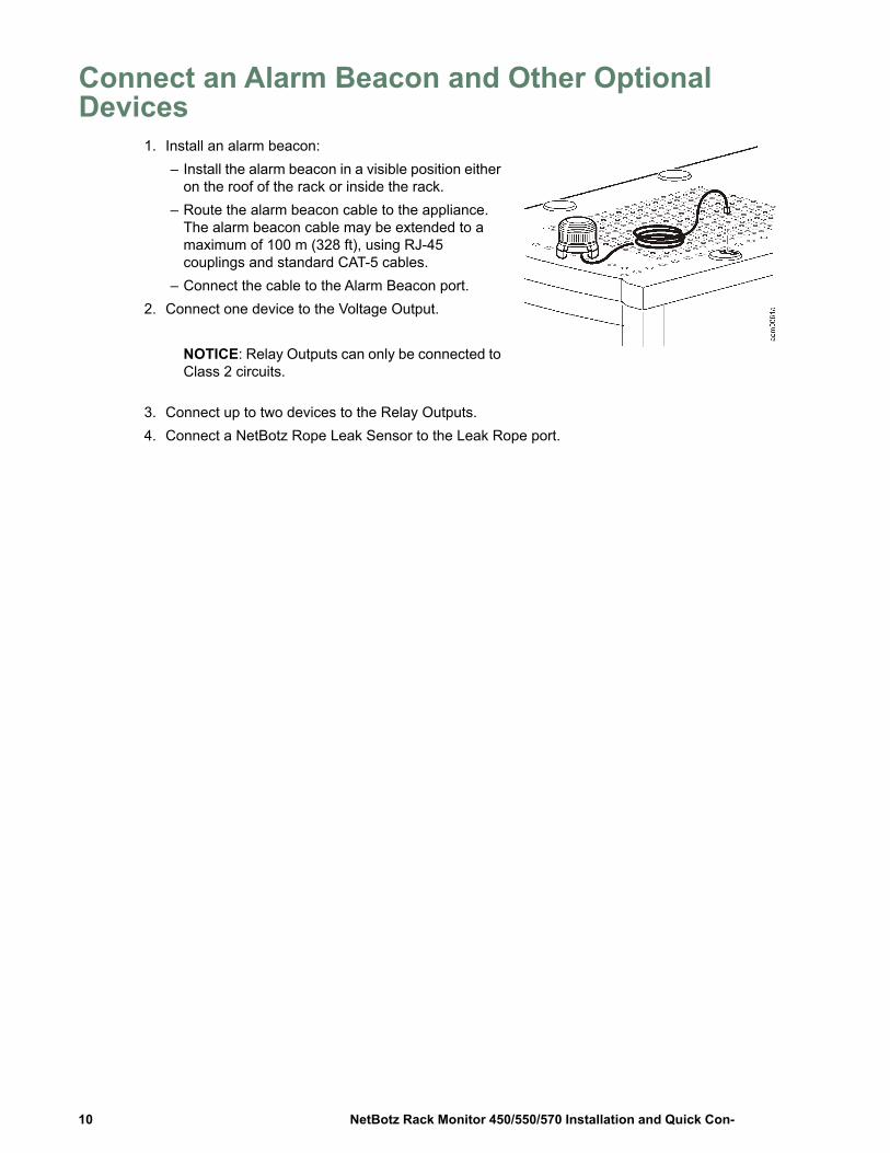
Connect an Alarm Beacon and Other Optional Devices
1. Install an alarm beacon:– Install the alarm beacon in a visible position either
on the roof of the rack or inside the rack.– Route the alarm beacon cable to the appliance.
The alarm beacon cable may be extended to a maximum of 100 m (328 ft), using RJ-45 couplings and standard CAT-5 cables.
– Connect the cable to the Alarm Beacon port.2. Connect one device to the Voltage Output.
NOTICE: Relay Outputs can only be connected to Class 2 circuits.
3. Connect up to two devices to the Relay Outputs.4. Connect a NetBotz Rope Leak Sensor to the Leak Rope port.
NetBotz Rack Monitor 450/550/570 Installation and Quick Con-10
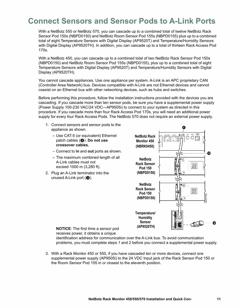
Connect Sensors and Sensor Pods to A-Link PortsWith a NetBotz 550 or NetBotz 570, you can cascade up to a combined total of twelve NetBotz Rack Sensor Pod 150s (NBPD0150) and NetBotz Room Sensor Pod 155s (NBPD0155) plus up to a combined total of eight Temperature Sensors with Digital Display (AP9520T) and Temperature/Humidity Sensors with Digital Display (AP9520TH). In addition, you can cascade up to a total of thirteen Rack Access Pod 170s.
With a NetBotz 450, you can cascade up to a combined total of two NetBotz Rack Sensor Pod 150s (NBPD0150) and NetBotz Room Sensor Pod 155s (NBPD0155), plus up to a combined total of eight Temperature Sensors with Digital Display (AP9520T) and Temperature/Humidity Sensors with Digital Display (AP9520TH).
You cannot cascade appliances. Use one appliance per system. A-Link is an APC proprietary CAN (Controller Area Network) bus. Devices compatible with A-Link are not Ethernet devices and cannot coexist on an Ethernet bus with other networking devices, such as hubs and switches.
Before performing this procedure, follow the installation instructions provided with the devices you are cascading. If you cascade more than ten sensor pods, be sure you have a supplemental power supply (Power Supply 100-230 VAC/24 VDC—AP9505i) to connect to your system as directed in this procedure. If you cascade more than four Rack Access Pod 170s, you will need an additional power supply for every four Rack Access Pods. The NetBotz 570 does not require an external power supply.
1. Connect sensors and sensor pods to the appliance as shown.– Use CAT-5 (or equivalent) Ethernet
patch cables (. Do not use crossover cables.
– Connect to in and out ports as shown.– The maximum combined length of all
A-Link cables must notexceed 1000 m (3,280 ft).
2. Plug an A-Link terminator into the unused A-Link port ().
NOTICE: The first time a sensor pod receives power, it obtains a unique identification address for communication over the A-Link bus. To avoid communication problems, you must complete steps 1 and 2 before you connect a supplemental power supply.
3. With a Rack Monitor 450 or 550, if you have cascaded ten or more devices, connect one supplemental power supply (AP9505i) to the 24 VDC Input jack of the Rack Sensor Pod 150 or the Room Sensor Pod 155 in or closest to the eleventh position.
(NBRK0450)
(NBPD0150)
Rack SensorPod 150
NetBotz
NetBotz RackMonitor 450
(NBPD0150)
Rack SensorPod 150
NetBotz
(AP9520TH)
HumiditySensor
Temperature/
11NetBotz Rack Monitor 450/550/570 Installation and Quick Con-
Initial ConfigurationNOTICE: Disregard the procedures in this section if you have a StruxureWare Data Center Expert server as part of your system. See the documentation for your StruxureWare device for more information.
OverviewYou must configure the following TCP/IP settings before the appliance can operate on a network:
• IP address of the appliance• Subnet mask• Default gatewayNOTICE: If a default gateway is unavailable, use the IP address of a computer that is located on the
same subnet as the appliance and that is usually running. The appliance uses the default gateway to test the network when traffic is very light.
Obtain network settings using DHCP
By default, your appliance obtains its network settings using DHCP. When you connect the appliance to your network and apply power to the unit, it automatically attempts to contact a DHCP server. The appliance waits 30 seconds for a response.
If the DHCP server is configured to provide a hostname, the appliance requests either its configured hostname or ‘netbotzxxxxxx’ (where xxxxxx is the last 6 digits of the MAC address of the appliance) as a hostname associated with the IP address granted by the DHCP server. You can then use a web browser to connect to the appliance using the address http://netbotzxxxxxx without any additional configuration.
The appliance also requests DNS server addresses, a DNS domain, SMTP server addresses, and NTP server addresses from the DHCP server.
Install the Advanced View
NOTICE: The Java Runtime Environment used by the Advanced View application is always installed, regardless of whether the installation target already has a suitable JRE installed.
Microsoft® Windows® Systems: To install the applications and the JRE on a computer running Windows XP SP1 or SP2, Windows 2000, Windows Vista, Windows 7, or Windows 10, download install.exe from apc.com or dcimsupport.apc.com. Follow the prompts to complete the installation of your software.
Linux Systems: To install the applications and the JRE on a computer running Red Hat® Enterprise Linux® 4 or 5, or Fedora™ Core 24, download install.bin from apc.com or dcimsupport.apc.com. Follow the prompts to complete the installation of your software.
Configure network settings using a terminal emulator
1. Connect a USB A to USB mini B cable to the Console Port on the NetBotz appliance and a USB port on your computer.
2. Plug the power cord provided with your NetBotz appliance into a wall outlet, and then connect it to the AC line inlet.
NetBotz Rack Monitor 450/550/570 Installation and Quick Con-12
The green Power LED illuminates immediately after you apply power to the appliance. The unit can take up to two minutes to initialize, depending on appliance configuration. The red Alert LED illuminates when the appliance detects an alert condition.
3. Open a serial connection on your terminal emulator using port settings 38400 baud, 8, 1, N.4. Enter the root account user name and password for the appliance (root/apc, by default) and click
OK. 5. Specify the network settings of your appliance to use network settings assigned by a DHCP
server, or provide an IP address, subnet mask, and gateway address for the appliance. You can specify a NAT proxy name or IP address to be used by a NAT Proxy server in your network to allow users to connect to the appliance from outside the firewall. You can also specify speed and duplex settings for use by this interface, or use Auto Negotiate.
6. Save your configuration settings, and close the terminal emulator.7. Test the IP connection of the NetBotz appliance. Start your Web browser and type the IP address
of the appliance into the address field. Press Enter. If the NetBotz appliance is online and properly configured, the web client displays in the browser window.
Install a wireless network device
You can install a third-party wireless network device by connecting it to the Ethernet port on the appliance using an Ethernet cable. APC currently supports the D-Link DWL-G820, a wireless Ethernet bridge.
To install and configure a third-party wireless network device, see the instructions provided with that device.
13NetBotz Rack Monitor 450/550/570 Installation and Quick Con-
The NetBotz Configuration WizardUse the Configuration Wizard to configure the following settings on your appliance:
• Domain Name Server Settings• Clock and Calendar Settings• Region Settings• Administrator User ID and Password• E-Mail Settings• E-Mail Alert Notification Recipients
The Configuration Wizard downloads the latest available version of BotzWare to your appliance.
When you finish configuring your appliance with the Wizard, your appliance monitors your environment for lack of adequate air flow and for changes in temperature and humidity and detects motion in the area in which the camera is located. Alert conditions detected by any of these sensors generate an e-mail to send to a specified e-mail address.
The Configuration Wizard runs each time you use the Advanced View with your NetBotz appliance until you complete all of the steps in the Wizard or check Don’t Show Configuration Wizard Next Time. You can run the Wizard again by selecting Configuration Wizard from the Advanced View Tools drop-down list.
Access an ApplianceOverview
After the appliance is running on your network, you can access the configured appliance through the web client or the Advanced View.
Administrator account user ID and password
Your NetBotz appliance has a pre-configured Administrator account. The User ID and Password for this account are:
• User ID: apc• Password: apc
NOTICE: To increase security, be sure to use the Advanced View Users task to change the default User ID and Password for the Administrator account.
NetBotz Rack Monitor 450/550/570 Installation and Quick Con-14
Root account user ID and password
Your NetBotz appliance has a pre-configured root account. The root account is used only for appliance communications that are performed using the USB Console Port, e.g., when you use a terminal emulator to specify network settings. The default User ID and Password for this account are:
• User ID: root• Password: apc
You cannot change the root account User ID. To increase security, use the Advanced View Change Root Password Tool to change the default root account password.
Lost password recovery
To recover from a lost password:
1. Locate the reset switch on the rear of the appliance, to the right of the AC Line Inlet port.2. Use a thin wire such as a paper clip to press the reset switch for 10 seconds. This causes the
system to restart.3. Once the system restarts, log in within two minutes using the default login values:• For Advanced View:
– User ID: apc– Password: apc
• For the console:– User ID: root– Password: apc
If you do not log in within two minutes after holding down the reset switch, you must repeat the procedure.
4. After you log in, change the password to increase security.
15NetBotz Rack Monitor 450/550/570 Installation and Quick Con-
Web Client
The NetBotz web client provides a real-time overview of alerts and device details, including sensor readings and images captured by camera pods, for a NetBotz appliance running version 4.2 and above.
For advanced appliance configuration and system administration, use the NetBotz Advanced View. NOTICE: Advanced View is not supported on mobile devices.
For a list of supported w
eb browsers and versions, see the release notes on apc.com or dcimsupport.apc.com.
Advanced View
Use the Advanced View to view sensor data, camera images, and other appliance data in a custom Java application. You can also use the Advanced View to generate relay output actions and configure all appliance features. The Advanced View is a stand-alone application that must be installed on a supported network-attached computer.
For more information on the web client or the Advanced View, see the NetBotz Appliance User’s Guide.
NetBotz Rack Monitor 450/550/570 Installation and Quick Con-16
NetBotz Quick ConfigurationOnce you configure, install, and apply power to your appliance, use the Advanced View to perform the following procedures.
• Configure Appliance Settings: Configure the appliance Clock, DNS, Region, Network Interface (hostname, NAT proxy, and speed and duplex settings), E-mail Servers, and Proxy settings.
• Configure Alert Actions: Configure the Play Audio Alert and Primary E-mail Notification alert actions.
Configure appliance settings
Open the Advanced View and perform the following Appliance Settings tasks. The icons associated with each task are located in the Configuration pane, in the Appliance Settings region.
1. Set the Clock settings. By default, your appliance synchronizes the system clock with the default NTP servers. If network access to these servers is not permitted, double-click on the Clock icon and specify your NTP server address or manually specify clock settings.
2. Set DNS settings. Double-click the DNS icon and specify the DNS Domain and at least one DNS Server address.
3. Set the Region settings. Double-click the Region icon and set Locale and Time Zone. The default settings are US and Central Standard Time.
4. Specify a hostname for your appliance. Double-click on Network Interfaces and specify a hostname for your appliance. Optionally, specify a NAT proxy name or IP address to be used by a NAT Proxy server in your network to allow users connect to the appliance from outside the firewall. You can also specify speed and duplex settings for use by this interface, or use the default setting, Auto Negotiate.
5. Assign a unique User ID and Password to the Administrator account. By default, User ID and Password for the Administrator account are both apc. To increase security, double-click the Users icon, double-click NetBotz Admin Account, and specify a unique User ID and password for the administrator account.
6. Set your E-mail Server settings. This is the e-mail server that your appliance uses to deliver e-mail alert notifications. Double-click the E-mail Servers icon, and configure the following settings:
a. (Optional) Provide a From address.b. In the SMTP server field, type the hostname or IP address of your SMTP server (for
example, mail.yourcompany.com).c. If necessary, specify a Port value (25, by default).d. Select an SSL option for authentication and certificate verification. Check with your
network administrator for further assistance.e. Click Test E-mail Server, type in your e-mail address, and click OK. An e-mail is sent to
your address when an alert is detected. Confirm that you received the test e-mail and continue.
7. If your network uses an HTTP or Socks proxy server, double-click the Proxy icon and specify your Proxy settings. If you are unsure whether you use an HTTP or Socks proxy, check with your network administrator.
17NetBotz Rack Monitor 450/550/570 Installation and Quick Con-
Configure alert actions
You can configure your appliance to play audio alert notifications through the headphone/speaker jack on your Camera Pod 160 or Sensor Pod 120 or to send an e-mail alert notification to your e-mail address when sensor thresholds are violated.
Open the Advanced View and perform the following Pod/Alerts Settings tasks. The icons associated with each task are located in the Configuration pane, in the Pod/Alerts Settings region.
1. Open the Alert Actions task. Double-click the Alert Actions icon to open the Alert Action Configuration window.
2. Click Add... to open the Select Alert Action window, select Play Audio Alert and click OK to open the Add Alert Action window.
3. In the Alert Action Name field, type a name for this alert action (for example, Play Audio Alert). 4. Select your Camera Pod from the Output Device drop box. Optionally, adjust the Volume%
setting.5. Click OK to close the Add Alert Action window and continue. Your newly created alert action is
included in the list of Alert Actions.6. Select Primary E-mail Notification from the list of defined alert actions and click Edit.7. Check Include a sound clip with the alert. This ensures that any alert e-mailed to you includes
a sound clip with any camera images that are delivered. You can disable this option later, if the file size of alert notifications is too large.
8. Click Add..., type your e-mail address in the Add E-mail Address window, and click OK. 9. Click OK to close the Edit Alert Action window and continue.10.Click OK to close the Alert Action Configuration window.
NetBotz Rack Monitor 450/550/570 Installation and Quick Con-18
Upgrade Options
Software Feature UpgradesThe BotzWare on your appliance can be upgraded using the Upgrade task in the Advanced View. The following software packs can be added to your appliance.
• Advanced Software Pack, which includes the following features:– Block out masking for camera images– Digitally signed clips– Enhanced audio features– Detailed appliance location information– Increased number of definable users and user capabilities
NOTICE: The features of this pack are standard on the NetBotz 570 and 550. • 5 Node Scanner/IPMI Pack, which provide IPMI and SNMP scanner integration
When you upgrade your appliance, the connected pods are automatically updated. If your network includes more than one appliance, you must perform the upgrade on all appliances. Valid data is not available during the upgrade.
Hardware UpgradesYou can upgrade your NetBotz appliance hardware in the following ways:
• Add Camera Pod 160s, Sensor Pod 150s, Sensor Pod 155s, Rack Access Pods 170s (Netbotz 570 and NetBotz 550 only), and CCTV Adapter Pod 120s to your NetBotz appliance.
• Add a wireless sensor network to your appliance using the NetBotz Wireless Sensor 180, NetBotz USB Coordinator & Router, and the NetBotz Wireless Temperature Sensor.
• Add a supported USB modem to a USB port on your appliance.• Add a supported USB digital I/O device to a USB port on your appliance.• Add supported USB-to-serial port device on your appliance.
The NetBotz Rack Monitor 570, NetBotz Rack Monitor 550, and the NetBotz Rack Monitor 450 support the NetBotz Sensor Pod 120 and the NetBotz Camera Pod 120.
19NetBotz Rack Monitor 450/550/570 Installation and Quick Con-
Add pods to your appliance
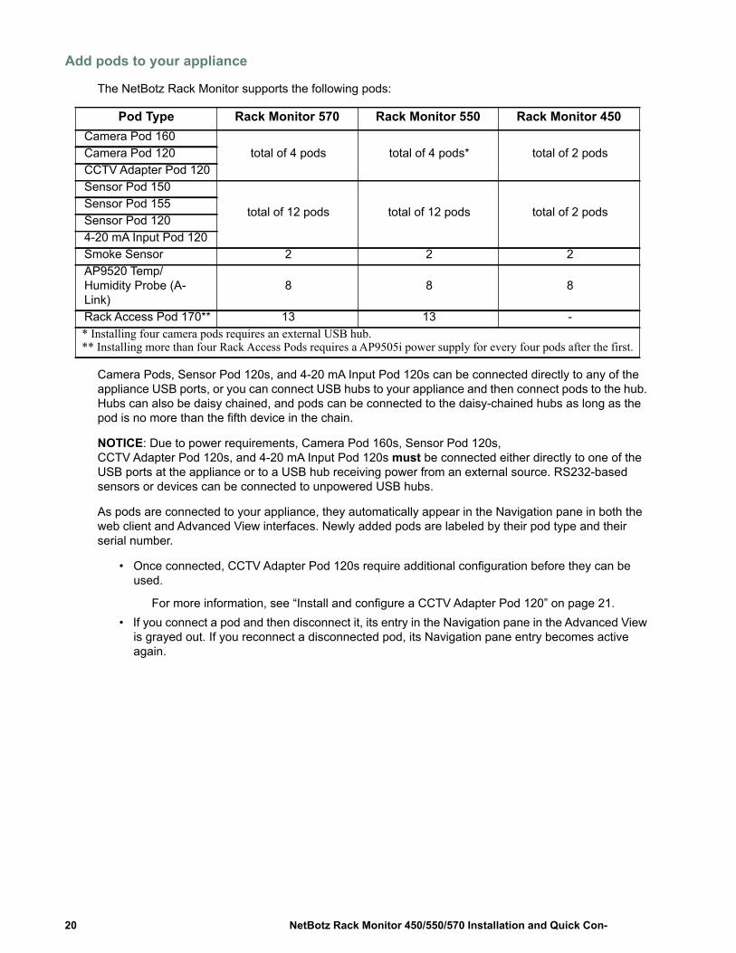
The NetBotz Rack Monitor supports the following pods:
Camera Pods, Sensor Pod 120s, and 4-20 mA Input Pod 120s can be connected directly to any of the appliance USB ports, or you can connect USB hubs to your appliance and then connect pods to the hub. Hubs can also be daisy chained, and pods can be connected to the daisy-chained hubs as long as the pod is no more than the fifth device in the chain.
NOTICE: Due to power requirements, Camera Pod 160s, Sensor Pod 120s, CCTV Adapter Pod 120s, and 4-20 mA Input Pod 120s must be connected either directly to one of the USB ports at the appliance or to a USB hub receiving power from an external source. RS232-based sensors or devices can be connected to unpowered USB hubs.
As pods are connected to your appliance, they automatically appear in the Navigation pane in both the web client and Advanced View interfaces. Newly added pods are labeled by their pod type and their serial number.
• Once connected, CCTV Adapter Pod 120s require additional configuration before they can be used.
For more information, see “Install and configure a CCTV Adapter Pod 120” on page 21.• If you connect a pod and then disconnect it, its entry in the Navigation pane in the Advanced View
is grayed out. If you reconnect a disconnected pod, its Navigation pane entry becomes active again.
Pod Type Rack Monitor 570 Rack Monitor 550 Rack Monitor 450Camera Pod 160
total of 4 pods total of 4 pods* total of 2 podsCamera Pod 120CCTV Adapter Pod 120Sensor Pod 150
total of 12 pods total of 12 pods total of 2 podsSensor Pod 155Sensor Pod 1204-20 mA Input Pod 120Smoke Sensor 2 2 2AP9520 Temp/Humidity Probe (A-Link)
8 8 8
Rack Access Pod 170** 13 13 -* Installing four camera pods requires an external USB hub. ** Installing more than four Rack Access Pods requires a AP9505i power supply for every four pods after the first.
NetBotz Rack Monitor 450/550/570 Installation and Quick Con-20

Install and configure a CCTV Adapter Pod 120. To install a CCTV Adapter Pod 120, connect your video source to the appropriate DIN, BNC, or RCA video input jack on the pod. Use the USB cable to connect your pod to your NetBotz appliance, or to a USB hub connected to the appliance. To reduce radio frequency noise and emissions from the USB cable, clamp one clamp-on ferrite onto the USB cable within 51-76 mm (2-3 in) of the end that connects to the pod, and the second clamp-on ferrite onto the USB cable within 51-76 mm (2-3 in) of the end that connects to your appliance or to the USB hub.
After you connect your CCTV Adapter Pod 120 and video source to your appliance, use the Advanced View to configure the pod.
To configure your pod:
1. Start the Advanced View. From the Appliance drop-down list, select the IP address of the appliance to which you have connected the CCTV Adapter Pod 120. Log in to the appliance using a user account that has administrator privileges. After you log in, confirm that the newly connected CCTV Adapter Pod 120 appears in the Navigation Pane. The default label for CCTV Adapter Pod 120s is CCTV Video Pod serial, where serial is the serial number of the pod.
2. Select the Configuration button and double-click the Camera Pods icon (located in the Pod/Sensor Settings portion of the Configuration pane).
3. In the Camera Pod Configuration pane, select the entry that corresponds to the CCTV Adapter Pod 120 and then click Capture.
4. The Camera Capture Settings window opens. In addition to the fields that are available when you use this window to configure Camera Pod 160s, one additional control is available when you configure a CCTV Adapter Pod 120: – Video Format: Used to specify the format in which video is transmitted by the video source.
Available selections include: NTSC-M, NTSC-Japan, PAL-B, PAL-D, PAL-G, PAL-H, PAL-I, PAL-M, PAL-N Combination, and SECAM.
5. Use the controls in the Camera Capture Settings window to configure the camera and image capture settings for use with the pod. To see an example of an image capture using the currently selected Video Format, Brightness, Contrast, and Image Quality settings, click Apply. The sample image in the Capture window will be updated using the new values. When you are finished, click OK to save your changes to the appliance.
Your video source should now appear in the Advanced View Cameras pane. Once configured, you can use the video source in the same ways you use Camera Pod 160s.
21NetBotz Rack Monitor 450/550/570 Installation and Quick Con-

Connect a wireless sensor network
You can connect a wireless sensor network to a NetBotz appliance, v4.4 and above, to monitor temperature and humidity using the NetBotz USB Coordinator & Router (NBWC100U), NetBotz Wireless Temperature Sensor (NBWS100T and NBWS100H), and NetBotz Wireless Sensor Pod 180 (NBPD0180). Additional sensors allow you to monitor rack door access and multiple temperature readings (Wireless Sensor Pod 180 only).
Each wireless sensor network must have one and only one Coordinator, connected to a USB Type A port on the NetBotz appliance. Routers are powered by an AC-USB adapter, not directly connected to the NetBotz appliance. End Devices are powered by batteries.
The following wireless devices can be configured as the Coordinator or as a Router on your wireless network:
The following wireless devices can be configured as an End Device on your wireless network:
In a data center environment where obstructions are common, a range of 50 feet is typical.
NOTICE: Only the devices listed above are compatible with the NetBotz wireless sensor network. Other devices will not function and may damage the appliance and other wireless devices.
The NetBotz Room Monitor 455 and Rack Monitor 450, 550, and 570 appliances support a total of 48 wireless devices on the wireless sensor network, including the Coordinator and Routers.
NOTICE: In NetBotz versions prior to v4.5.3, the NetBotz Rack Monitor 450 appliance supports a total of 26 wireless devices on the wireless sensor network, including the Coordinator and Routers.
NOTICE: A total of 26 Wireless Sensor Pod 180 devices are supported on NetBotz v4.3 appliances, including the Coordinator and Routers. The NetBotz Wireless Sensor Pod 180 is the only wireless device supported on the wireless sensor network in BotzWare v4.3 and Advanced View v4.3.
You configure the wireless sensor network in Advanced View in the following order:
• Add the extended addresses (MAC) of the wireless devices to the commission list in the Wireless Sensor Setup task.
• Apply the commission list to save it to the NetBotz appliance.• Configure the Coordinator (Wireless Sensor Pod 180 only).
The order in which you configure your wireless sensor network and power your wireless devices is important.
For information about installing and configuring your wireless devices, see the installation manual that came with the NetBotz Wireless USB Coordinator & Router, NetBotz Wireless Temperature Sensor, and NetBotz Wireless Sensor Pod 180.
Wireless Device Range Part NumberUSB Coordinator & Router 100 ft - line of sight NBWC100UWireless Sensor Pod 180 100 ft - line of sight NBPD0180
Wireless Device Range Part NumberWireless Temperature
Sensor 100 ft - line of sight NBWS100T NBWS100H
Wireless Sensor Pod 180 100 ft - line of sight NBPD0180
NetBotz Rack Monitor 450/550/570 Installation and Quick Con-22
Add wireless devices to Advanced View. You can add wireless sensors to the network in the following ways:
• Enter the MAC addresses for the wireless sensors manually.• Use any barcode or QR code scanner to save a list of MAC addresses to a text file, one address
per line, and copy and paste it into the dialog.• Use a hand-held USB scanner to manually scan the MAC address bar code on the USB
Coordinator & Router label, or the QR code on the Wireless Temperature Sensor or Wireless Sensor Pod 180, directly into the dialog.
• Once the Coordinator is connected to the appliance, allow powered wireless devices to automatically join and form the network using Auto Join.
Some bar code and QR code scanners return the part number, serial number, and MAC address on one line: XN:NBWC100U%SN:XXXXXX123456%MAC:00C0B70000XXXXXX. To add a sensor to your wireless network, enter only the alphanumeric MAC address of each sensor in the “Add Addresses” dialog in the Advanced View.
USB scanner. When you use a USB scanner with document capture capabilities, only the extended address (MAC) of each wireless device will appear in the list in Advanced View in the correct format.
1. Attach a hand-held USB scanner with document capture capabilities to a computer running the NetBotz Advanced View.
2. With the Advanced View open to the “Add Addresses” dialog in the Wireless Sensor Setup task, scan the QR code on the label of each wireless device.
3. Click Apply Commission List to save the list to the NetBotz appliance.
Update wireless devices. Once you have added all the wireless devices to your wireless network, you can check their current firmware revision in the Wireless Sensor Setup task. If an update is available, the Firmware Update Available button will be activated in the display.
For more information about updating your wireless devices, see the NetBotz Appliance User’s Guide.
23NetBotz Rack Monitor 450/550/570 Installation and Quick Con-
Connect a USB modem
You can enhance the network communication capabilities of your appliance by connecting a supported USB modem to your appliance. The following USB modems are supported for use with the appliance:
• MultiTech® MultiModem® GPRS• MultiTech MultiMobile™ USB• MultiTech MultiModem Cell• MultiTech MultiModem Cell 3G MTCBA-H5• MultiTech MultiModem iCell 3G MTCMR-H5• MultiTech QuickCarrier® USB-D, MTD-H5-2.0• Option GlobeSurfer® iCon
Connect the USB modem to your appliance, or to a USB hub that is connected to the appliance. Once the modem is recognized as a serial port by the appliance, use the Advanced View Serial Devices task to specify the modem that is associated with the serial port. Once you specify the modem model, use the Advanced View PPP/Modem task to configure your appliance for PPP communications.
To uninstall your USB modem, use the Serial Devices task in the Advanced View to remove the device.
Connect a USB digital I/O device
You can increase the number of dry contact sensors that can be connected to your appliance by connecting a supported USB digital I/O device to your appliance. The following USB digital I/O devices are supported for use with the appliance:
• Sealevel® SeaLINK PIO-48 (adds 48 digital I/O connections)• Sealevel SeaI/O 462U (adds 96 digital I/O connections)• Sealevel SeaI/O 463U (adds 96 digital I/O connections)• Sealevel SeaI/O 450U (adds 16 digital I/O connections)
To connect a USB digital I/O device to your appliance:
1. Remove power from the appliance. 2. Connect the USB digital I/O device to your appliance, or to a USB hub that is connected to the
appliance.3. Apply power to the appliance. 4. Once the appliance has finished booting up, power for the digital I/O device will be recognized as
a serial port by the appliance. Use the Advanced View Serial Devices task to specify the digital I/O device that is associated with the serial port.
5. Use the Advanced View Dry Contacts task to configure any dry contact sensors you have connected to your digital I/O device.
To uninstall your USB digital I/O device, use the Serial Devices task in the Advanced View to remove the device.
NetBotz Rack Monitor 450/550/570 Installation and Quick Con-24
Connect an APC Switched Rack PDU
To connect an APC Switched Rack PDU to your appliance, use a USB-to-serial cable (NBAC0226, available from NetBotz and NetBotz resellers) to add serial ports to your appliance. Connect your USB-to-serial cable to your appliance, or to a USB hub that is connected to the appliance.
NOTICE: The serial port connector on the USB-to-serial port converter cable is a male connector. If the Rack PDU you are connecting to the cable also has a male connector you will need a female-to-female connector null modem cable or converter block to connect the device to the USB-to-serial cable.
Once you connect the USB-to-serial cable to your appliance, you can connect the Rack PDU to the cable for use with your appliance.
Supported APC Switched Rack PDUs. APC Switched Rack PDUs with firmware version 2.74 and lower are supported at this time.
Install intelligent power strips. Connect the intelligent power strip to a serial port on your USB-to-serial cable. Use the Advanced View Serial Devices task to specify which serial port-based sensor you have connected to the appliance.
The sensor readings associated with the device will appear in the web client and Advanced Views once you complete installation.
To uninstall your intelligent power strip, use the Serial Devices task in the Advanced View to remove the device.
Connect external sensors
To install an external sensor, plug the sensor into an available External Port on any Sensor Pod 150, Sensor Pod 155, or Sensor Pod 120.
NOTICE: When connecting a sensor to a Sensor Pod 120, be sure to note both the sensor pod serial number, located on the back of the pod, and the number of the External Port on the pod when you connect the cable. You will need this information when you use the sensor pod task to configure your appliance. The External Port number is printed above the port on the pod.
The female connectors on the NetBotz 120 Sensor Pod units are Version 2, NetBotz DIN standard connectors and can only accept male, Version 2, NetBotz DIN Sensor Cables. The new Version 3 products use standard RJ-45 connectors.
If the external sensor cable is not long enough, use an Extension Cable for External Sensors, available in 15 m (50 ft) and 30 m (100 ft) lengths from your NetBotz reseller, to lengthen the cable.
When you have finished installing external sensors, use the Sensor Pods task to configure the appliance to use the external sensor. Once you configure your appliance, an additional temperature sensor appears in the Sensor Data pane when the pod to which it is connected is selected from the Navigation pane. Use the Advanced View Sensor Pods task to specify thresholds for this external sensor.
25NetBotz Rack Monitor 450/550/570 Installation and Quick Con-
DisposalNOTICE: NetBotz Rack Monitor appliances contain non-replaceable, lithium coin-cell batteries. Do not attempt to replace the battery. Please take the battery into consideration when disposing of the appliance.
Clean the NetBotz 450/550/570To clean the device, gently wipe surfaces with a clean, dry cloth.
Specifications
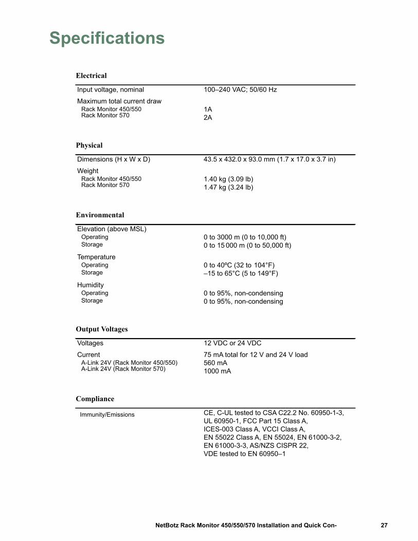
Electrical
Input voltage, nominal 100–240 VAC; 50/60 Hz
Maximum total current drawRack Monitor 450/550Rack Monitor 570
1A2A
Physical
Dimensions (H x W x D) 43.5 x 432.0 x 93.0 mm (1.7 x 17.0 x 3.7 in)
WeightRack Monitor 450/550Rack Monitor 570
1.40 kg (3.09 lb)1.47 kg (3.24 lb)
Environmental
Elevation (above MSL)OperatingStorage
0 to 3000 m (0 to 10,000 ft)0 to 15 000 m (0 to 50,000 ft)
TemperatureOperatingStorage
0 to 40ºC (32 to 104°F) –15 to 65°C (5 to 149°F)
HumidityOperatingStorage
0 to 95%, non-condensing0 to 95%, non-condensing
Output Voltages
Voltages 12 VDC or 24 VDC
CurrentA-Link 24V (Rack Monitor 450/550)A-Link 24V (Rack Monitor 570)
75 mA total for 12 V and 24 V load560 mA1000 mA
Compliance
Immunity/Emissions CE, C-UL tested to CSA C22.2 No. 60950-1-3, UL 60950-1, FCC Part 15 Class A, ICES-003 Class A, VCCI Class A, EN 55022 Class A, EN 55024, EN 61000-3-2, EN 61000-3-3, AS/NZS CISPR 22, VDE tested to EN 60950–1
27NetBotz Rack Monitor 450/550/570 Installation and Quick Con-
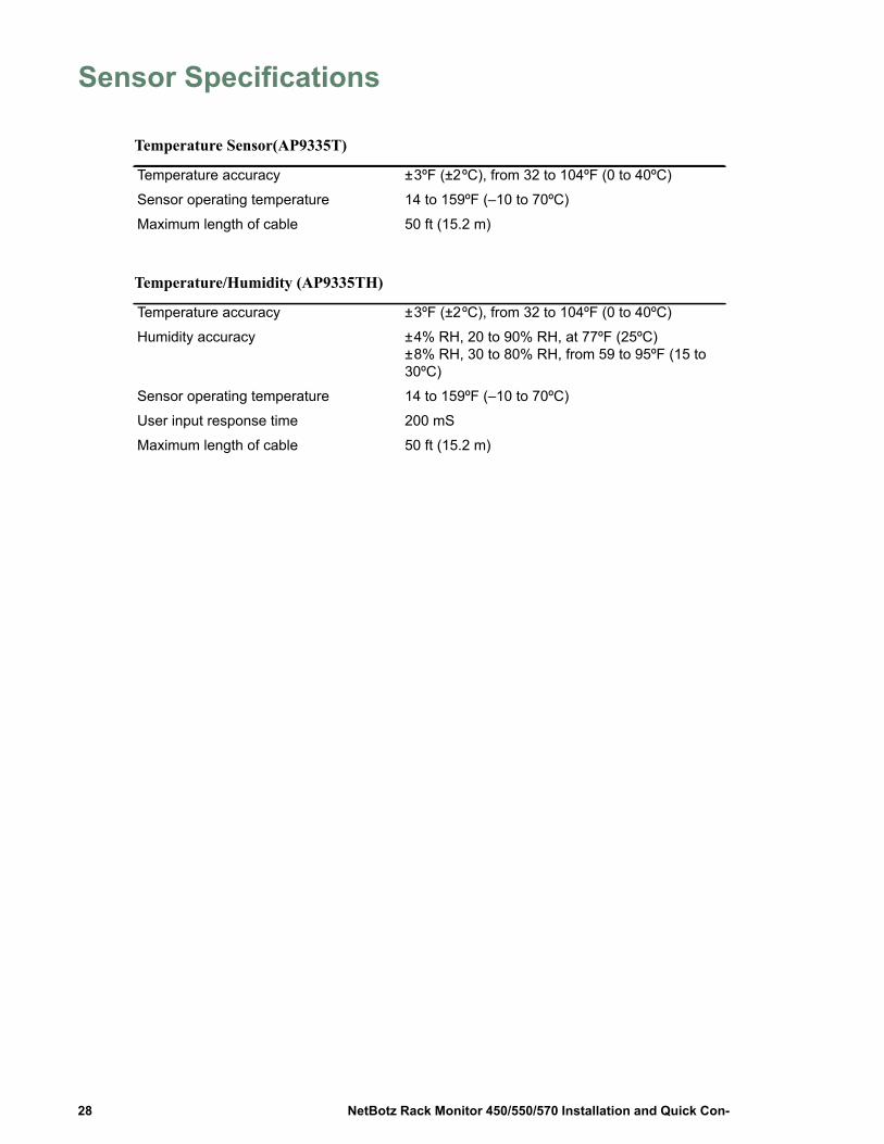
Sensor Specifications
Temperature Sensor(AP9335T)
Temperature accuracy ± 3ºF (±2 ºC), from 32 to 104ºF (0 to 40ºC)
Sensor operating temperature 14 to 159ºF (–10 to 70ºC)
Maximum length of cable 50 ft (15.2 m)
Temperature/Humidity (AP9335TH)
Temperature accuracy ± 3ºF (±2 ºC), from 32 to 104ºF (0 to 40ºC)
Humidity accuracy ± 4% RH, 20 to 90% RH, at 77ºF (25ºC)± 8% RH, 30 to 80% RH, from 59 to 95ºF (15 to 30ºC)
Sensor operating temperature 14 to 159ºF (–10 to 70ºC)
User input response time 200 mS
Maximum length of cable 50 ft (15.2 m)
NetBotz Rack Monitor 450/550/570 Installation and Quick Con-28
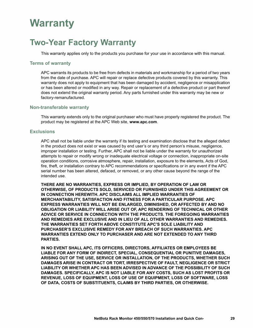
Warranty
Two-Year Factory WarrantyThis warranty applies only to the products you purchase for your use in accordance with this manual.
Terms of warranty
APC warrants its products to be free from defects in materials and workmanship for a period of two years from the date of purchase. APC will repair or replace defective products covered by this warranty. This warranty does not apply to equipment that has been damaged by accident, negligence or misapplication or has been altered or modified in any way. Repair or replacement of a defective product or part thereof does not extend the original warranty period. Any parts furnished under this warranty may be new or factory-remanufactured.
Non-transferable warranty
This warranty extends only to the original purchaser who must have properly registered the product. The product may be registered at the APC Web site, www.apc.com.
Exclusions
APC shall not be liable under the warranty if its testing and examination disclose that the alleged defect in the product does not exist or was caused by end user’s or any third person’s misuse, negligence, improper installation or testing. Further, APC shall not be liable under the warranty for unauthorized attempts to repair or modify wrong or inadequate electrical voltage or connection, inappropriate on-site operation conditions, corrosive atmosphere, repair, installation, exposure to the elements, Acts of God, fire, theft, or installation contrary to APC recommendations or specifications or in any event if the APC serial number has been altered, defaced, or removed, or any other cause beyond the range of the intended use.
THERE ARE NO WARRANTIES, EXPRESS OR IMPLIED, BY OPERATION OF LAW OR OTHERWISE, OF PRODUCTS SOLD, SERVICED OR FURNISHED UNDER THIS AGREEMENT OR IN CONNECTION HEREWITH. APC DISCLAIMS ALL IMPLIED WARRANTIES OF MERCHANTABILITY, SATISFACTION AND FITNESS FOR A PARTICULAR PURPOSE. APC EXPRESS WARRANTIES WILL NOT BE ENLARGED, DIMINISHED, OR AFFECTED BY AND NO OBLIGATION OR LIABILITY WILL ARISE OUT OF, APC RENDERING OF TECHNICAL OR OTHER ADVICE OR SERVICE IN CONNECTION WITH THE PRODUCTS. THE FOREGOING WARRANTIES AND REMEDIES ARE EXCLUSIVE AND IN LIEU OF ALL OTHER WARRANTIES AND REMEDIES. THE WARRANTIES SET FORTH ABOVE CONSTITUTE APC’S SOLE LIABILITY AND PURCHASER’S EXCLUSIVE REMEDY FOR ANY BREACH OF SUCH WARRANTIES. APC WARRANTIES EXTEND ONLY TO PURCHASER AND ARE NOT EXTENDED TO ANY THIRD PARTIES.
IN NO EVENT SHALL APC, ITS OFFICERS, DIRECTORS, AFFILIATES OR EMPLOYEES BE LIABLE FOR ANY FORM OF INDIRECT, SPECIAL, CONSEQUENTIAL OR PUNITIVE DAMAGES, ARISING OUT OF THE USE, SERVICE OR INSTALLATION, OF THE PRODUCTS, WHETHER SUCH DAMAGES ARISE IN CONTRACT OR TORT, IRRESPECTIVE OF FAULT, NEGLIGENCE OR STRICT LIABILITY OR WHETHER APC HAS BEEN ADVISED IN ADVANCE OF THE POSSIBILITY OF SUCH DAMAGES. SPECIFICALLY, APC IS NOT LIABLE FOR ANY COSTS, SUCH AS LOST PROFITS OR REVENUE, LOSS OF EQUIPMENT, LOSS OF USE OF EQUIPMENT, LOSS OF SOFTWARE, LOSS OF DATA, COSTS OF SUBSTITUENTS, CLAIMS BY THIRD PARTIES, OR OTHERWISE.
29NetBotz Rack Monitor 450/550/570 Installation and Quick Con-

NO SALESMAN, EMPLOYEE OR AGENT OF APC IS AUTHORIZED TO ADD TO OR VARY THE TERMS OF THIS WARRANTY. WARRANTY TERMS MAY BE MODIFIED, IF AT ALL, ONLY IN WRITING SIGNED BY AN APC OFFICER AND LEGAL DEPARTMENT.
Warranty claims
Customers with warranty claims issues may access the APC customer support network through the Support page of the APC Web site, www.apc.com/support. Select your country from the country selection pull-down menu at the top of the Web page. Select the Support tab to obtain contact information for customer support in your region.
NetBotz Rack Monitor 450/550/570 Installation and Quick Con-30

31NetBotz Rack Monitor 450/550/570 Installation and Quick Con-

NetBotz Rack Monitor 450/550/570 Installation and Quick Con-32
This manual is available in English on the APC Web site (www.apc.com).
Dieses Handbuch ist in Deutsch auf der APC Webseite (www.apc.com) verfügbar.
Este manual está disponible en español en la página web de APC (www.apc.com).
Ce manuel est disponible en français sur le site internet d’APC (www.apc.com).
Questo manuale è disponibile in italiano sul sito web di APC (www.apc.com).
Este manual está disponível em português no site da APC (www.apc.com).
Данное руковод тво на ру ко языке до тупно на айте APC (www.apc.com )
APC (www.apc.com)
www.apc.com
Scan the QR code to download the latest version of this manual to your mobile device.
dcimsupport.apc.com
Worldwide Customer SupportCustomer support for this or any other product is available at no charge in any of the following ways:
• Visit the StruxureWare for Data Centers DCIM Support Community web site.– dcimsupport.apc.com
Access the most recent documentation and get quick solutions from Schneider Electric experts and a community of your peers.
• Visit the APC web site to access documents in the APC Knowledge Base and to submit customer support requests.– www.apc.com
Connect to localized APC web sites for specific countries, each of which provides customer support information.– www.apc.com/support/
Global support searching APC Knowledge Base and using e-support.• Contact the Customer Care Center by telephone or e-mail.
– Local, country-specific centers: go to www.apc.com/support/contact for contact information.
For information on how to obtain local customer support, contact the Schneider Electric representative or other distributors from whom you purchased your product.
2/2017990-3291G-001
© 2017 Schneider Electric. All Rights Reserved. Schneider Electric, APC, the APC logo, and NetShelter are trademarks owned by Schneider Electric Industries SAS or its affiliated companies.