rack & pinion lubrication systems - atlanta drive s · rack & pinion lubrication systems...
TRANSCRIPT

Dimensions in mm ZE – 11/2015
Rack & Pinion Lubrication Systems
Page
Lubricator 125 cm3 ZE-2
Lubricator 475 cm3 ZE-3
Selection of the Lubrication for Rack Drives ZE-4
Lubrication System ZE-5 – 6
Felt Gear ZE-7 – 8
Lubrication Equipment, Accessories ZE – 9
Lubricating Systems and Accessories ZE – 10
Dimensions in mmZE – 2 2/2015
Rack & Pinion Lubrication Systems
Order Code Fig.
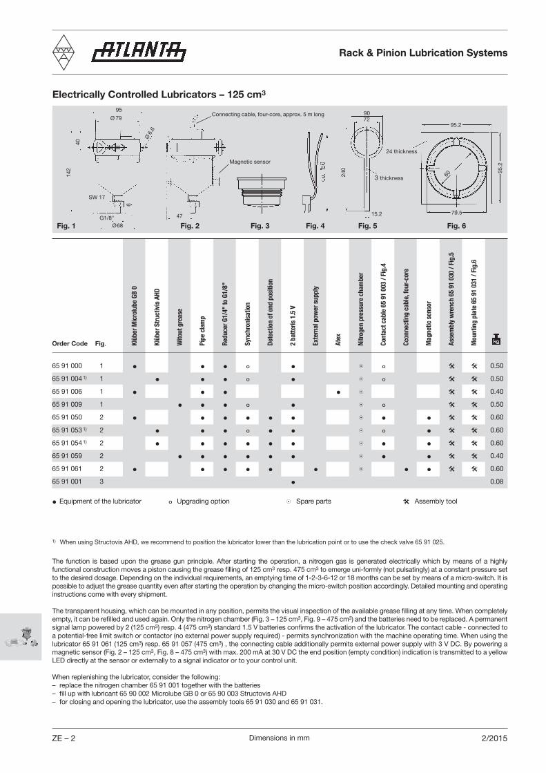
Electrically Controlled Lubricators – 125 cm3
Fig. 3Fig. 2
40
95
Ø6.
6
SW 17
Ø68
47
142
Ø 79
Fig. 1
95.2
24 thickness
79.5
95.2
Fig. 4
240
3 thickness
15.2
7290
60
Fig. 5
6
Fig. 6G1/8"
Connecting cable, four-core, approx. 5 m long
Magnetic sensor
65 91 000 1 • • • º • 8 º @ @ 0.50
65 91 004 1) 1 • • • º • 8 º @ @ 0.50
65 91 006 1 • • • • 8 @ @ 0.40
65 91 009 1 • • • º • 8 º @ @ 0.50
65 91 050 2 • • • • • • 8 • • @ @ 0.60
65 91 053 1) 2 • • • º • • 8 º • @ @ 0.60
65 91 054 1) 2 • • • • • • 8 • • @ @ 0.60
65 91 059 2 • • • • • • 8 • • @ @ 0.40
65 91 061 2 • • • • • • 8 • • @ @ 0.60
65 91 001 3 • 0.08
• Equipment of the lubricator º Upgrading option 8Spare parts @ Assembly tool
Klüb
er M
icro
lube
GB
0
Klüb
er S
truc
tivis
AHD
Wito
ut g
reas
e
Pipe
cla
mp
Redu
cer G
1/4"
to G
1/8"
Sync
hron
isat
ion
Dete
ctio
n of
end
pos
ition
2 ba
tteris
1.5
V
Exte
rnal
pow
er s
uppl
y
Atex
Nitr
ogen
pre
ssur
e ch
ambe
r
Asse
mbl
y w
renc
h 65
91
030
/ Fig
.5
Cont
act c
able
65
91 0
03 /
Fig.
4
Ccon
nect
ing
cabl
e, fo
ur-c
ore
Mag
netic
sen
sor
Mou
ntin
g pl
ate
65 9
1 03
1 / F
ig.6
The function is based upon the grease gun principle. After starting the operation, a nitrogen gas is generated electrically which by means of a highly functional construction moves a piston causing the grease filling of 125 cm3 resp. 475 cm3 to emerge uni-formly (not pulsatingly) at a constant pressure set to the desired dosage. Depending on the individual requirements, an emptying time of 1-2-3-6-12 or 18 months can be set by means of a micro-switch. It is possible to adjust the grease quantity even after starting the operation by changing the micro-switch position accordingly. Detailed mounting and operating instructions come with every shipment.
The transparent housing, which can be mounted in any position, permits the visual inspection of the available grease filling at any time. When completely empty, it can be refilled and used again. Only the nitrogen chamber (Fig. 3 – 125 cm3, Fig. 9 – 475 cm3) and the batteries need to be replaced. A permanent signal lamp powered by 2 (125 cm3) resp. 4 (475 cm3) standard 1.5 V batteries confirms the activation of the lubricator. The contact cable - connected to a potential-free limit switch or contactor (no external power supply required) - permits synchronization with the machine operating time. When using the lubricator 65 91 061 (125 cm3) resp. 65 91 057 (475 cm3) , the connecting cable additionally permits external power supply with 3 V DC. By powering a magnetic sensor (Fig. 2 – 125 cm3, Fig. 8 – 475 cm3) with max. 200 mA at 30 V DC the end position (empty condition) indication is transmitted to a yellow LED directly at the sensor or externally to a signal indicator or to your control unit.
When replenishing the lubricator, consider the following:– replace the nitrogen chamber 65 91 001 together with the batteries– fill up with lubricant 65 90 002 Microlube GB 0 or 65 90 003 Structovis AHD– for closing and opening the lubricator, use the assembly tools 65 91 030 and 65 91 031.
1) When using Structovis AHD, we recommend to position the lubricator lower than the lubrication point or to use the check valve 65 91 025.

Dimensions in mm ZE – 31/2015
Electrically Controlled Lubricators – 475 cm3
Fig. 8
60
Ø 120
Ø 8.5
Ø104
180
105
Fig. 7
135
Fig. 9
20
Fig. 10 Fig. 11G1/4"
143
Ø120 Ø90
135
30 thickness
Ø130Ø105
280
3 thickness
67
The function is based upon the grease gun principle. After starting the operation, a nitrogen gas is generated electrically which by means of a highly functional construction moves a piston causing the grease filling of 125 cm3 resp. 475 cm3 to emerge uni-formly (not pulsatingly) at a constant pressure set to the desired dosage. Depending on the individual requirements, an emptying time of 1-2-3-6-12 or 18 months can be set by means of a micro-switch. It is possible to adjust the grease quantity even after starting the operation by changing the micro-switch position accordingly. Detailed mounting and operating instructions come with every shipment.
The transparent housing, which can be mounted in any position, permits the visual inspection of the available grease filling at any time. When completely empty, it can be refilled and used again. Only the nitrogen chamber (Fig. 3 – 125 cm3, Fig. 9 – 475 cm3) and the batteries need to be replaced. A permanent signal lamp powered by 2 (125 cm3) resp. 4 (475 cm3) standard 1.5 V batteries confirms the activation of the lubricator. The contact cable - connected to a potential-free limit switch or contactor (no external power supply required) - permits synchronization with the machine operating time. When using the lubricator 65 91 061 (125 cm3) resp. 65 91 057 (475 cm3) , the connecting cable additionally permits external power supply with 3 V DC. By powering a magnetic sensor (Fig. 2 – 125 cm3, Fig. 8 – 475 cm3) with max. 200 mA at 30 V DC the end position (empty condition) indication is transmitted to a yellow LED directly at the sensor or externally to a signal indicator or to your control unit.
When replenishing the lubricator, consider the following:– replace the nitrogen chamber 65 91 001 together with the batteries– fill up with lubricant 65 90 002 Microlube GB 0 or 65 90 003 Structovis AHD– for closing and opening the lubricator, use the assembly tools 65 91 030 and 65 91 031.
1) When using Structovis AHD, we recommend to position the lubricator lower than the lubrication point or to use the check valve 65 91 025.
SW27
8
Order Code Fig.
65 91 007 7 • • • • 8 @ @ 0.9
65 91 014 1) 7 • • • • 8 @ @ 0.9
65 91 069 7 • • • • 8 @ @ 0.5
65 91 067 8 • • • • • 8 • @ @ 1.0
65 91 056 8 • • • • • • 8 • • @ @ 1.1
65 91 057 8 • • • • • • 8 • • @ @ 1.1
65 91 068 8 • • • • • • 8 • • @ @ 0.6
65 91 058 8 • • • • • • 8 • • @ @ 1.1
• Equipment of the lubricator º Upgrading option 8Spare parts @ Assembly tool
Klüb
er M
icro
lube
GB
0
Klüb
er S
truc
tivis
AHD
Wito
ut g
reas
e
Pipe
cla
mp
Redu
cer G
1/2"
to G
1/4"
Sync
hron
isat
ion
Dete
ctio
n of
end
pos
ition
4 ba
tteris
1.5
V
Exte
rnal
pow
er s
uppl
y
Atex
Nitr
ogen
pre
ssur
e ch
ambe
r / fi
g. 9
Asse
mbl
y w
renc
h 65
91
032
/ Fig
. 10
Ccon
nect
ing
cabl
e, fo
ur-c
ore
Mag
netic
sen
sor
Mou
ntin
g pl
ate
65 9
1 03
3 / F
ig. 1
1
Rack & Pinion Lubrication Systems

Dimensions in mmZE – 4 1/2015
Lubrication of Rack and Pinion DrivesWhen lubricating rack and pinion drives by means of a felt gearwheel and electrically controlled lubricator the optimal grease supply can be seen from the diagram below.
For lubrication with sliding brush use the next higher switch position. If, for example, micro-switch position 4 is chosen for felt-
Gearwheel lubrication, choose 3 for sliding-brush lubrication at the same speed and with the same module.
Pressure Build-UpSet all micro-switches to "ON". Pressure build-up time 6 – 8 hours. Then set the desired time. The micro-switch 7 must be always on. Before starting up the lubricator the connecting hose between felt wheel and lubricator should be filled and the felt wheel soaked with grease.
Battery Changing The guaranteed service life of the battery is 1 year. Then the battery should be replaced. Although the control lamp may still flash it is possible that the battery capacity has already decreased. The lubricator can also be operated by means of external power supply via an intermediate relay.
Recommended Lubricants for Rack Drives:
Felt Gear Lubrication: Klüber Microlube GB 0 Order Code 65 90 002 (1 kg) Klüber Structovis AHD Order Code 65 90 003 (1 kg)
Sliding Brush Lubrication: Klüber Microlube GB 0 Order Code 65 90 002 (1 kg)
Furthermore the following lubricants have been tested with good results. Oest Langzeitfett LT 200 BP Energrease LS EP 00 DEA Glissando 6833 EP 00 Fuchs Lubritech Gearmaster ZSA Molykote G-Rapid plus 3694
Grease Supply Rate for Felt Gear lubrication
Rack & Pinion Lubrication Systems

Dimensions in mm ZE – 51/2015
Lubricator Assemblies for HT High-Torque Gear Units with Pinion Shaft with Clamp Connection
Unit Mounting Possibilities
Ordering Example: a = 80, m = 4 helical tooth system, Fig. LO ⇒ 65 85 184 (Felt gear assembled according to the dimension "h2 = 85” of the mounting surface).
| - Straight For fig. 2, lubricators can be found on page ZE-2 and felt gears on page ZE-7Order Code / - Helical Fig. 1 Fig. 2 m z h h1 h2 h3 h4 b1 b2 s b H B L
ao = 50 95 96 49 33 17 3 30 113 140 10465 83 192 65 93 012 | 2 32 LU,RU RO,LO,RS,LS 25 37 1.4065 83 182 65 93 012 ⁄ 2 30 LU,RU RO,LO,RS,LS 25 37 1.4065 83 193 65 93 013 | 3 21 RS LU,RU RO,LO,LS 30 36 1.4465 83 183 65 93 013 ⁄ 3 20 RS LU,RU RO,LO,LS 30 36 1.4465 83 194 65 93 014 | 4 17 LU,RU RS RO,LO,LS 40 32 1.5465 83 184 65 93 014 ⁄ 4 15 LU,RU RS RO,LO,LS 40 32 1.54
ao = 63 115 80 64 48 29 3 41 133 162 13465 84 192 65 94 012 | 2 32 LU,RU RO,LO,RS,LS 25 37 2.0065 84 182 65 94 012 ⁄ 2 30 LU,RU RO,LO,RS,LS 25 37 2.0065 84 193 65 94 013 | 3 21 LU,RU RO,LO,RS LS 30 36 1.9065 84 183 65 94 013 ⁄ 3 20 LU,RU RO,LO,RS LS 30 36 1.9065 84 194 65 94 014 | 4 17 LU,RU,RS RO,LO,LS 40 32 2.0065 84 184 65 94 014 ⁄ 4 15 LU,RU,RS RO,LO,LS 40 32 2.00
ao = 80 130 103 85 57 36 3 51 148 198 15965 85 194 65 95 014 | 4 17,30* LU,RU LU*,RU* RO,LO,RS,LS RO*,LO*,RS*,LS* 40 32 2.5065 85 184 65 95 014 ⁄ 4 15,30* LU,RU LU*,RU* RO,LO,RS,LS RO*,LO*,RS*,LS* 40 32 2.5065 85 185 65 95 015 | 5 13 LU,RU RO,LO,RS,LS 50 35 2.7065 85 175 65 95 015 ⁄ 5 12 LU,RU RO,LO,RS,LS 50 35 2.7065 85 186 65 95 016 | 6 – 60 37 2.8065 85 176 65 95 016 ⁄ 6 13 LU,RU RO,LO,RS,LS 60 37 2.80
ao = 100 140 102 84 52 32 4 54 169 230 18265 86 185 65 96 015 1) | 5 15 LU,RU RO,LO,RS,LS 50 35 3.3065 86 175 65 96 015 1) ⁄ 5 15 LU,RU RO,LO,RS,LS 50 35 3.3065 86 186 65 96 016 1) | 6 13 LU,RU RO,LO,RS,LS 60 37 3.5065 86 176 65 96 016 1) ⁄ 6 13,15* LU,RU,LU*,RU* RO,LO,RS,LS,RO*,LO*,RS*,LS* 60 37 3.5065 86 188 65 96 018 1) | 8 – 80 38 4.3065 86 178 65 96 018 1) ⁄ 8 12 LU,RU RS RO,LO,LS 80 38 4.30
Toot
h Sy
stem
Fig. 1
Fig. 2
Rack & Pinion Lubrication Systems

Dimensions in mmZE – 6 1/2015
Lubricator Assemblies for HP/E/B/ Gear Units
Unit Mounting Possibilities – see page ZE-5
| - Straight For fig. 2, lubricators can be found on page ZE-2 and felt gears on page ZE-7Order Code / - Helical Fig. 1 Fig. 2 m z h h1 h2 h3 h4 b1 b2 s b H B L
ao = 50 95 65 49 33 17 25 3 30 113 134 10465 93 190 65 93 002 | 2 21 LU, RU RO, LO, RS LS 25 1.4265 93 180 65 93 002 ⁄ 2 20 LU, RU RO, LO, RS LS 25 1.4265 93 192 65 93 002 | 2 32 LU, RU, LS RO, LO, RS 25 1.4065 93 182 65 93 002 ⁄ 2 30 LU, RU, LS RO, LO, RS 25 1.4065 93 193 65 93 003 | 3 21 RS LU, RU RO, LO, LS 30 1.4465 93 183 65 93 003 ⁄ 3 20 RS LU, RU RO, LO, LS 30 1.44
ao = 63 115 80 64 48 29 25 3 41 133 162 13465 94 192 65 94 002 | 2 32 LU, RU RO, LO, LS LS 25 1.7265 94 182 65 94 002 ⁄ 2 30 LU, RU RO, LO, LS LS 25 1.7265 94 193 65 94 003 | 3 21 RS LU, RU RO, LO, LS 30 1.7965 94 183 65 94 003 ⁄ 3 20 RS LU, RU RO, LO, LS 30 1.7965 94 194 65 94 004 | 4 17 LU, RU RS RO, LO, LS 40 1.9065 94 184 65 94 004 ⁄ 4 15 LU, RU RS RO, LO, LS 40 1.90
ao = 80 130 103 85 57 36 25 3 51 148 198 15965 95 192 65 95 002 | 2 32 LU, RU RO, LO, RS, LS 25 2.4065 95 182 65 95 002 ⁄ 2 30 LU, RU RO, LO, RS, LS 25 2.4065 95 193 65 95 003 | 3 21 LU, RU RO, LO, RS, LS 30 2.3965 95 183 65 95 003 ⁄ 3 20 LU, RU RO, LO, RS, LS 30 2.3965 95 194 65 95 004 | 4 17 LU, RU RS RO, LO, RS 40 2.5065 95 184 65 95 004 ⁄ 4 15 LU, RU RS RO, LO, RS 40 2.50
ao = 100 140 102 84 52 32 25 4 54 169 230 18265 96 194 65 96 004 1) | 4 17, 30* LU, RU, RS RO, LO, LS, LU*, RU* RO*, LO*, LS* 40 2.6065 96 184 65 96 004 1) ⁄ 4 15, 30* LU, RU, RS RO, LO, LS, LU*, RU* RO*, LO*, LS* 40 2.6065 96 185 65 96 005 1) | 5 13 LU, RU RS RO, LO, LS 50 3.3065 96 175 65 96 005 1) ⁄ 5 12 LU, RU RS RO, LO, LS 50 3.3065 96 186 65 96 006 1) | 6 – 60 3.5065 96 176 65 96 006 1) ⁄ 6 13 LU, RU, RS LS RO, LO 60 3.50
ao = 125 198 171 128 102 – 25 4 78 227 290 22565 97 185 65 97 005 1) | 5 15 LU, RU RO, LO, RS, LS 50 3.7365 97 175 65 97 005 1) ⁄ 5 15 LU, RU RO, LO, RS, LS 50 3.7365 97 186 65 97 006 1) | 6 13 RS LU, RU RO, LO LS 60 3.8865 97 176 65 97 006 1) ⁄ 6 13, 15* RS LU, RU, LU*,RU* RO, LO LS, RO*, LO*, LS*, RS* 60 3.8865 97 188 65 97 008 1) | 8 – 80 4.5065 97 178 65 97 008 1) ⁄ 8 12 LU, RU RO, LO, LS, RS 80 4.50
Toot
h Sy
stem
Fig. 1
Fig. 2
Rack & Pinion Lubrication Systems

Dimensions in mm ZE – 71/2015
Fig. 1| Straight Tooth System
Fig. 2/ Helical Tooth Systems RH
b1
d1 dk
d
b1
dk
dd1
Fig. 3\ Helical Tooth Systems LH
b1d
1 dk
d
L
d1
b1G 1/4"
GD
l
D G d1
M4
Felt Gears Mounting Shafts
* For use with HP/E/B Gear Units ** For use with HT Gear Units
Fig. 4
Fig. 5
65 91 140 1 1 I 40 40.0 42.0 12 15 7.565 91 100 4 1 12 15 30 40 10 M8 135.065 91 126 1 1.5 I 26 39.0 42.0 12 15 7.265 91 116 2 1.5 ⁄ 24 38.2 42.0 12 15 7.065 91 106 3 1.5 \ 24 38.2 42.0 12 15 7.065 91 100 4 1.5 12 15 30 40 10 M8 135.065 91 024 1 1.591 5 I 24 38.2 41.4 12 15 6.865 91 100 4 1.591 5 12 15 30 40 10 M8 135.065 91 228 1 2 I 19 38.0 42.0 12 25 11.065 91 229 2 2 ⁄ 18 38.2 42.0 12 25 11.065 91 218 3 2 \ 18 38.2 42.0 12 25 11.065 91 236 1 2 I 36 72.0 76.0 12 25 22.065 91 234 2 2 ⁄ 34 72.2 76.2 12 25 22.065 91 200 4 2 12 25 30 50 10 M8 143.065 91 210* 5 2 12 25 30 50 M8 140.065 91 220** 5 2 12 25 30 62 M8 150.065 91 222 1 2.5 I 22 55.0 60.0 12 25 25.065 91 200 4 2.5 12 25 30 50 10 M8 143.065 91 210 5 2.5 12 25 30 50 M8 140.065 91 220 5 2 12 25 30 62 M8 150.065 91 328 1 3 I 19 57.0 63.0 12 30 37.065 91 329 2 3 ⁄ 18 57.3 63.0 12 30 36.065 91 318 3 3 \ 18 57.3 63.0 12 30 36.065 91 300 4 3 12 30 30 55 10 M8 147.065 91 310* 5 3 12 30 30 55 M8 145.065 91 320** 5 3 12 30 30 66 M8 155.065 91 018 1 3.183 10 I 18 57.3 63.6 12 30 36.065 91 300 4 3.183 10 12 30 30 55 10 M8 147.065 91 310 5 3.183 10 12 30 30 55 M8 145.065 91 320 5 3 12 30 30 66 M8 155.065 91 428 1 4 I 19 76.0 84.0 12 40 98.065 91 429 2 4 ⁄ 18 76.5 84.0 12 40 97.065 91 418 3 4 \ 18 76.5 84.0 12 40 97.065 91 400 4 4 12 40 30 65 10 M8 154.065 91 410* 5 4 12 40 30 65 M8 150.065 91 420** 5 4 12 40 30 72 M8 160.065 91 517 3 5 \ 17 90.2 100.0 20 50 133.065 91 518 1 5 I 18 90.0 100.0 20 50 133.065 91 529 2 5 ⁄ 17 90.2 100.0 20 50 133.065 91 500 4 5 20 50 50 75 15 M12 520.065 91 510 5 5 20 50 40 75 M8 510.065 91 520 5 5 20 50 40 85 M8 520.0
Order Code Fig. Module Pitch Flank Direction No. of Teeth d dk d1 b1 D L l G
Rack & Pinion Lubrication Systems

Dimensions in mmZE – 8 1/2015
Fig. 1| Straight Tooth System
Fig. 2/ Helical Tooth System RH
b1
d1 dk
d
b1
dk
dd1
Fig. 3\ Helical Tooth System LH
b1
d1 dk
d
L
d1
b1G 1/4"
GD
l
D G d1
M4
Felt Gears Mounting Shafts
* For use with HP/E/B Gear Units ** For use with HT Gear Units
Fig. 4
Fig. 5
65 91 617 3 6 \ 17 108.2 120.0 20 60 234.065 91 618 1 6 I 18 108.0 120.0 20 60 234.065 91 629 2 6 ⁄ 17 108.2 120.0 20 60 234.065 91 600 4 6 20 60 50 85 15 M12 545.065 91 610* 5 6 20 60 40 85 M8 535.065 91 620** 5 6 20 60 40 97 M8 550.065 91 817 3 8 \ 17 144.3 160.0 20 80 562.065 91 818 1 8 I 18 144.0 160.0 20 80 562.065 91 829 2 8 ⁄ 17 144.3 160.0 20 80 562.065 91 800 4 8 20 80 50 105 15 M12 595.065 91 810* 5 8 20 80 50 105 M8 280.065 91 820** 5 8 20 80 50 118 M8 600.065 91 117 3 10 \ 17 180.4 200.0 25 100 750.065 91 118 1 10 I 18 180.0 200.0 25 100 750.065 91 129 2 10 ⁄ 17 180.4 200.0 25 100 750.065 91 101 4 10 25 100 50 125 15 M12 650.065 91 111 5 10 25 100 50 125 M8 645.065 91 114 3 12 \ 14 178.3 202.0 25 100 800.065 91 115 1 12 I 15 180.0 204.0 25 100 800.065 91 124 2 12 ⁄ 14 178.3 202.0 25 100 800.065 91 102 4 12 25 100 50 145 15 M12 830.065 91 112 5 12 25 100 50 145 M8 810.0
Order Code Fig. Module Pitch Flank Direction No. of Teeth d dk d1 b1 D L l G
Rack & Pinion Lubrication Systems

Dimensions in mm ZE – 91/2015
Fig. 1
Order Code Fig. Description For Module
65 91 010 1 Sliding -type lubricating brush, round, with internal thread 1, 1.5, 2, 3, 4 1765 91 011 2 Sliding -type lubricating brush, flat, with internal thread 5, 6, 8 2065 91 012 3 Sliding -type lubricating brush, flat, with internal thread 10, 12 409 08 05 003 4 Reducer 8
Sliding Brush Lubrication
The sliding brush (of MS with sturdy Nylon bristles) can be used in combination with our lubricators for lubricating either the rack or the pinion. During the assembly of the sliding brush onto the lubricator with 125 cm³ or the house-connection set, the existing lubricator reducer (Fig. 4) must be used. Using the lubricator with 475 cm³ the existing lubricator reducer must be used in combination with the reducer out of Fig. 4.
SW17
G ¼”
27
25
G ¼”
SW17
6
Fig. 5
Order Code Fig. Description
65 91 020 5 Hose-connection set comprising: 25 2 m plastic hose Alumin. hose coupling with inside thread Alumin. hose coupling with outside thread 65 91 021 5 Hose-connection set comprising: 25 2 m plastic hose filled with GB0 Alumin. hose coupling with inside thread Alumin. hose coupling with outside thread 65 91 025 6 Non-return valve 0.2 bar
Hose Connection Set
Fig. 3
Reducer
Non-Return Valve
Remark:Before starting the hose-connection set must be filled up with lubricant. Lubrication see on page ZE-4.
Fig. 2 Fig. 4
Fig. 6
Rack & Pinion Lubrication Systems

Dimensions in mmZE – 10 1/2015
Lubrication Information
Lubricator Assemblies for gear unit center distances 50 mm to 125 mm
Lubricator Assemblies for center distance 32 mm available on request
Lubrication by means of felt gear
Check-valve, if lubricating point is lower than lubricator
Non-lubricated length
Lubrication over the full length
Lubrication of 2 lubrication points
Lube lines equally longlubricator type 475 cm3 recommendedCheck-valve recommended at both lubrication points
Lubrication by means of sliding brush
Reducer ¼“ to 1/8“ required and check valve
Lubrication over the full length
Non-lubricated length
Lubrication by means of felt gear is possible in any position
Lubrication with sliding brush limited to max. 60° tilt
Important information for optimum lubrication:– Lube lines filled with lubricant– Felt gear or sliding brush soaked with lubricant – Pressure available in lubricant metering device– Dosage properly set at lubricant metering device
Rack & Pinion Lubrication Systems