radar equation2
TRANSCRIPT

8/3/2019 Radar Equation2
http://slidepdf.com/reader/full/radar-equation2 1/25
RADAR EQUATION
Assigned By: Sir Irfan
Presented By: SADIQ
ABID
Peak Power of RADAR & SNR
8/3/2019 Radar Equation2
http://slidepdf.com/reader/full/radar-equation2 2/25
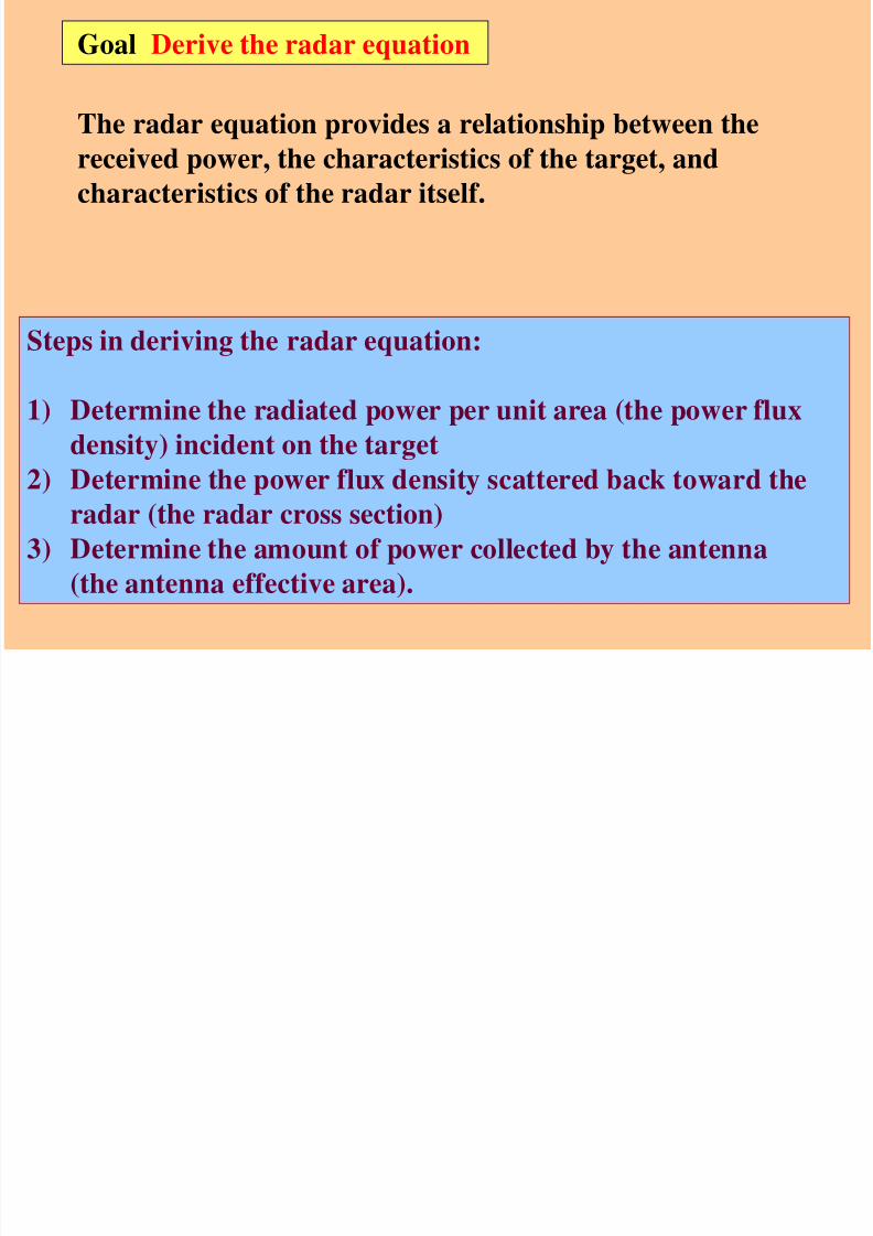
Goal Derive the radar equation
The radar equation provides a relationship between the
received power, the characteristics of the target, andcharacteristics of the radar itself.
Steps in deriving the radar equation:
1) Determine the radiated power per unit area (the power flux
density) incident on the target2) Determine the power flux density scattered back toward the
radar (the radar cross section)
3) Determine the amount of power collected by the antenna
(the antenna effective area).

8/3/2019 Radar Equation2
http://slidepdf.com/reader/full/radar-equation2 3/25
24 RPP t
isotropic
So power flux density ( P, watts/m 2) at a distance R from an
isotropic antenna is:
(1)
Consider an isotropic antenna that transmits radiation equally
in all directions
Where Pt is the transmitted power

8/3/2019 Radar Equation2
http://slidepdf.com/reader/full/radar-equation2 4/25
24 R
GP
Pt
inc
Since in Radar we used directed antenna to transmit power in
particular direction.So gain(G) is multiplied with Power density .
So from (1)
(2)
8/3/2019 Radar Equation2
http://slidepdf.com/reader/full/radar-equation2 5/25
24 R
GP p t
inc
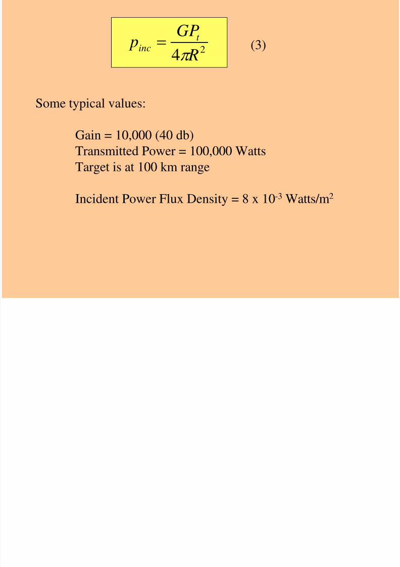
(3)
Some typical values:
Gain = 10,000 (40 db)Transmitted Power = 100,000 Watts
Target is at 100 km range
Incident Power Flux Density = 8 x 10⁻³ Watts/m2

8/3/2019 Radar Equation2
http://slidepdf.com/reader/full/radar-equation2 6/25
Radar cross section: Radar cross sectional area of a target(σ)
determines density back to the Radar.
So re radiated power density back to Radar is:
Aereradiated .Pr
The echo signal which is captured by the Radar is:
24.
RisnP
(4)
(5)

8/3/2019 Radar Equation2
http://slidepdf.com/reader/full/radar-equation2 7/25
So put equation (2) and equation (3) in (4) We get:
4216Pr
R
AeGPt
(6)
Where:
Pt=transmitted power
Pr=received power
G=gain of AntennaAe=antenna effective aperture
σ=cross sectional of the target

8/3/2019 Radar Equation2
http://slidepdf.com/reader/full/radar-equation2 8/25
2:Peak Power of RADAR & SNR
8/3/2019 Radar Equation2
http://slidepdf.com/reader/full/radar-equation2 9/25
A continuous-wave radar transmission may be easily figured because the
transmitter operates continuously.
However pulsed radar transmitters are switched on and off to provide range
timing information with each pulse.
The amount of energy in this waveform is important because maximum range
is directly related to transmitter output power.
Introduction

8/3/2019 Radar Equation2
http://slidepdf.com/reader/full/radar-equation2 10/25

8/3/2019 Radar Equation2
http://slidepdf.com/reader/full/radar-equation2 11/25
Pave = (Ppeak )Duty Cycle
Pave= Ppeak.(τ /T)
Where:
τ=pulse width in (μ) seconds
T=pulse repetition interval in (m) second

8/3/2019 Radar Equation2
http://slidepdf.com/reader/full/radar-equation2 12/25
SNR…….???

8/3/2019 Radar Equation2
http://slidepdf.com/reader/full/radar-equation2 13/25
Internal Noise:
It is generated by all electronic components and appears as random
variations superimposed on the desired echo signal.
The lower the power of the echo signal, the more difficult it is to separate it
from the noise.
Noise figure:It is a measure of the noise produced by a receiver compared to an ideal
receiver, and this needs to be minimized.
Noise

8/3/2019 Radar Equation2
http://slidepdf.com/reader/full/radar-equation2 14/25
In modern radar systems, due to the high performance of their receivers,
the internal noise is typically about equal to or lower than the externalscene noise.
External Noise: due to environmental effects natural thermal radiation
of the background scene surrounding the target of interest.
flicker noise: which is a random fluctuation in an electrical signal it
occurs due to ions bombarment and diffusion in a materials.It depends on 1/f and much lower than thermal noise when the
frequency is high.
Noise

8/3/2019 Radar Equation2
http://slidepdf.com/reader/full/radar-equation2 15/25
signal-to-noise ratio(SNR): SNR is defined as the ratio of a signal power
to the noise power within the desired signal.
SNR compares the level of a desired signal (such as targets) to the level
of background noise.
Higher SNR, the better it is in isolating actual targets from the
surrounding noise signals.
SNR

8/3/2019 Radar Equation2
http://slidepdf.com/reader/full/radar-equation2 16/25
3: Pulse Integration

8/3/2019 Radar Equation2
http://slidepdf.com/reader/full/radar-equation2 17/25
A pulse integrator is a improvement technique to address
gains in probability of detection by using multiple transmit
pulses.
This gain will be achieved by inserted in receiving path radarsignal processor adding radar returns (thus the word
integrator) from different successive pulse periods.
Pulse Integration

8/3/2019 Radar Equation2
http://slidepdf.com/reader/full/radar-equation2 18/25
Depending on location of the pulse integrator in the signal
processing chain this process is referred to as:coherent integration
non-coherent integration
Pulse Integration

8/3/2019 Radar Equation2
http://slidepdf.com/reader/full/radar-equation2 19/25
With coherent integration we insert a coherent integrator, or signal
processor, between the matched filter and amplitude detector as
shown in Figure 1.
The signal processor samples the return from each transmit pulse at
a spacing equal to the range resolution of the radar set and adds thereturns from N pulses. After it accumulates the N pulse sum it
performs the amplitude detection and threshold check.
Coherent Integration
8/3/2019 Radar Equation2
http://slidepdf.com/reader/full/radar-equation2 20/25
The Non-Coherent Integrator is placed after the amplitude or
square law detector as shown in Figure 2.
The name non-coherent integration derives from the fact that,
since the signal has undergone amplitude or square law
detection, the phase information is lost.
The non-coherent integrator operates in the same fashion as the
coherent integrator in that it sums the returns from N pulses
before performing the threshold check
Non-coherent Integration

8/3/2019 Radar Equation2
http://slidepdf.com/reader/full/radar-equation2 21/25
In older radars the pulse integration was implemented via the
persistence on displays plus the integrating capability of a humanoperator.
Non-coherent Integration

8/3/2019 Radar Equation2
http://slidepdf.com/reader/full/radar-equation2 22/25
4: Power aperture product

8/3/2019 Radar Equation2
http://slidepdf.com/reader/full/radar-equation2 23/25
Partial performance of phased array radar relies on its power-aperture product
( z).
which is the product of the average radiated power and the effective arrayaperture area.
Power aperture product
AePeve Z ).(

8/3/2019 Radar Equation2
http://slidepdf.com/reader/full/radar-equation2 24/25
It can be seen that when the target goes away from the reciver the improvements
factor becomes better.
Improvements is due to auto correlation function

8/3/2019 Radar Equation2
http://slidepdf.com/reader/full/radar-equation2 25/25
Thanks