radiation protection and the management of radioactive waste in the oil and gas industry pub1171_web
DESCRIPTION
Radiation Protection and Radioactive Waste ManagementTRANSCRIPT
S a f e t y R e p o r t s S e r i e sN o . 3 4
R a d i a t i o n P r o t e c t i o n a n d t h e M a n a g e m e n t o f
R a d i o a c t i v e W a s t e i n t h e O i l a n d G a s I n d u s t r y
IAEA SAFETY RELATED PUBLICATIONS
IAEA SAFETY STANDARDS
Under the terms of Article III of its Statute, the IAEA is authorized to establish standardsof safety for protection against ionizing radiation and to provide for the application of thesestandards to peaceful nuclear activities.
The regulatory related publications by means of which the IAEA establishes safetystandards and measures are issued in the IAEA Safety Standards Series. This series coversnuclear safety, radiation safety, transport safety and waste safety, and also general safety (thatis, of relevance in two or more of the four areas), and the categories within it are SafetyFundamentals, Safety Requirements and Safety Guides.
Safety Fundamentals (blue lettering) present basic objectives, concepts and principles ofsafety and protection in the development and application of nuclear energy for peacefulpurposes.
Safety Requirements (red lettering) establish the requirements that must be met to ensuresafety. These requirements, which are expressed as ‘shall’ statements, are governed bythe objectives and principles presented in the Safety Fundamentals.
Safety Guides (green lettering) recommend actions, conditions or procedures for meetingsafety requirements. Recommendations in Safety Guides are expressed as ‘should’ state-ments, with the implication that it is necessary to take the measures recommended orequivalent alternative measures to comply with the requirements.
The IAEA’s safety standards are not legally binding on Member States but may beadopted by them, at their own discretion, for use in national regulations in respect of their ownactivities. The standards are binding on the IAEA in relation to its own operations and on Statesin relation to operations assisted by the IAEA.
Information on the IAEA’s safety standards programme (including editions in languagesother than English) is available at the IAEA Internet site
www-ns.iaea.org/standards/or on request to the Safety Co-ordination Section, IAEA, P.O. Box 100, A-1400 Vienna,Austria.
OTHER SAFETY RELATED PUBLICATIONS
Under the terms of Articles III and VIII.C of its Statute, the IAEA makes available andfosters the exchange of information relating to peaceful nuclear activities and serves as anintermediary among its Member States for this purpose.
Reports on safety and protection in nuclear activities are issued in other series, inparticular the IAEA Safety Reports Series, as informational publications. Safety Reports maydescribe good practices and give practical examples and detailed methods that can be used tomeet safety requirements. They do not establish requirements or make recommendations.
Other IAEA series that include safety related publications are the Technical ReportsSeries, the Radiological Assessment Reports Series, the INSAG Series, the TECDOCSeries, the Provisional Safety Standards Series, the Training Course Series, the IAEAServices Series and the Computer Manual Series, and Practical Radiation Safety Manualsand Practical Radiation Technical Manuals. The IAEA also issues reports on radiologicalaccidents and other special publications.
RADIATION PROTECTION AND THE MANAGEMENT OF
RADIOACTIVE WASTE IN THE OIL AND GAS INDUSTRY

The following States are Members of the International Atomic Energy Agency:
The Agency’s Statute was approved on 23 October 1956 by the Conference on the Statute ofthe IAEA held at United Nations Headquarters, New York; it entered into force on 29 July 1957.The Headquarters of the Agency are situated in Vienna. Its principal objective is “to accelerate andenlarge the contribution of atomic energy to peace, health and prosperity throughout the world’’.
© IAEA, 2003
Permission to reproduce or translate the information contained in this publication may beobtained by writing to the International Atomic Energy Agency, Wagramer Strasse 5, P.O. Box 100,A-1400 Vienna, Austria.
Printed by the IAEA in Austria
November 2003STI/PUB/1171
AFGHANISTANALBANIAALGERIAANGOLAARGENTINAARMENIAAUSTRALIAAUSTRIAAZERBAIJANBANGLADESHBELARUSBELGIUMBENINBOLIVIABOSNIA AND HERZEGOVINABOTSWANABRAZILBULGARIABURKINA FASOCAMEROONCANADACENTRAL AFRICAN REPUBLICCHILECHINACOLOMBIACOSTA RICACÔTE D’IVOIRECROATIACUBACYPRUSCZECH REPUBLICDEMOCRATIC REPUBLIC OF THE CONGODENMARKDOMINICAN REPUBLICECUADOREGYPTEL SALVADORERITREAESTONIAETHIOPIAFINLANDFRANCEGABONGEORGIAGERMANYGHANAGREECE
GUATEMALAHAITIHOLY SEEHONDURASHUNGARYICELANDINDIAINDONESIAIRAN, ISLAMIC REPUBLIC OF IRAQIRELANDISRAELITALYJAMAICAJAPANJORDANKAZAKHSTANKENYAKOREA, REPUBLIC OFKUWAITKYRGYZSTANLATVIALEBANONLIBERIALIBYAN ARAB JAMAHIRIYALIECHTENSTEINLITHUANIALUXEMBOURGMADAGASCARMALAYSIAMALIMALTAMARSHALL ISLANDSMAURITIUSMEXICOMONACOMONGOLIAMOROCCOMYANMARNAMIBIANETHERLANDSNEW ZEALANDNICARAGUANIGERNIGERIANORWAYPAKISTANPANAMAPARAGUAY
PERUPHILIPPINESPOLANDPORTUGALQATARREPUBLIC OF MOLDOVAROMANIARUSSIAN FEDERATIONSAUDI ARABIASENEGALSERBIA AND MONTENEGROSEYCHELLESSIERRA LEONESINGAPORESLOVAKIASLOVENIASOUTH AFRICASPAINSRI LANKASUDANSWEDENSWITZERLANDSYRIAN ARAB REPUBLICTAJIKISTANTHAILANDTHE FORMER YUGOSLAV REPUBLIC OF MACEDONIATUNISIATURKEYUGANDAUKRAINEUNITED ARAB EMIRATESUNITED KINGDOM OF GREAT BRITAIN AND NORTHERN IRELANDUNITED REPUBLIC OF TANZANIAUNITED STATES OF AMERICAURUGUAYUZBEKISTANVENEZUELAVIETNAMYEMENZAMBIAZIMBABWE

SAFETY REPORTS SERIES No. 34
RADIATION PROTECTION AND THE MANAGEMENT OF
RADIOACTIVE WASTE IN THE OIL AND GAS INDUSTRY
INTERNATIONAL ATOMIC ENERGY AGENCYVIENNA, 2003

IAEA Library Cataloguing in Publication Data
Radiation protection and the management of radioactive waste in the oiland gas industry. — Vienna : International Atomic Energy Agency,2003.
p. ; 24 cm. — (Safety reports series, ISSN 1020–6450 ; no. 34)STI/PUB/1171ISBN 92–0–114003–7Includes bibliographical references.
1. Radiation. — Safety measures 2. Petroleum industry and trade— Safety measures. 3. Oil industry — Safety measures. 4. Gasindustry — Safety measures. 5. Radioactive waste disposal — Safetymeasures. I. International Atomic Energy Agency. II. Series.
IAEAL 03–00342
FOREWORD
The oil and gas industry, a global industry operating in many MemberStates, makes extensive use of radiation generators and sealed and unsealedradioactive sources, some of which are potentially dangerous to human healthand to the environment if not properly controlled. In addition, significantquantities of naturally occurring radioactive material (NORM) originatingfrom the reservoir rock are encountered during production, maintenance anddecommissioning. The oil and gas industry operates in all climates and environ-ments, including the most arduous conditions, and is continuously challenged toachieve high efficiency of operation while maintaining a high standard of safetyand control — this includes the need to maintain control over occupationalexposures to radiation, as well as to protect the public and the environmentthrough the proper management of wastes that may be radiologically andchemically hazardous. The oil and gas industry is organizationally and techni-cally complex, and relies heavily on specialized service and supply companiesto provide the necessary equipment and expertise, including expertise inradiation safety.
The Safety Fundamentals on Radiation Protection and the Safety ofRadiation Sources (Safety Series No. 120), together with the InternationalBasic Safety Standards for Protection against Ionizing Radiation and for theSafety of Radiation Sources (Safety Series No. 115), set out the principles andbasic requirements for radiation protection and safety applicable to all activ-ities involving radiation exposure. The Safety Guide on OccupationalRadiation Protection (Safety Standards Series No. RS-G-1.1) providesguidance on meeting the occupational protection requirements of the Interna-tional Basic Safety Standards. The Principles of Radioactive WasteManagement (Safety Series No. 111-F) present the objectives and principles ofradioactive waste management, while the Safety Requirements on PredisposalManagement of Radioactive Waste, Including Decommissioning (SafetyStandards Series No. WS-R-2) set out the requirements for the predisposalaspect of radioactive waste management: requirements with respect to disposalare under development. The Safety Guide on Management of RadioactiveWaste from the Mining and Milling of Ores (Safety Standards Series No.WS-G-1.2) provides some relevant guidance for the management of NORMwastes similar to those produced in the oil and gas industry. Some of theguidance provided in two other Safety Guides: Decommissioning of Medical,Industrial and Research Facilities (Safety Standards Series No. WS-G-2.2) andRegulatory Control of Radioactive Discharges to the Environment (SafetyStandards Series No. WS-G-2.3) is also relevant to the oil and gas industry.

The purpose of this Safety Report is to provide practical information,based on good working practices, on radiation protection and radioactive wastemanagement in the oil and gas industry. It is intended to assist in meeting therelevant radiation safety requirements and promoting a common under-standing between the industry and regulatory bodies. The Safety Report will beof interest to regulatory bodies; oil and gas field operators and supportcompanies; workers and their representatives; health, safety and environ-mental professionals; and health and safety training officers.
This Safety Report was drafted and finalized in six consultants meetingsand one Technical Committee meeting, held during the period 1997–2002. Thedraft was also sent to a number of additional experts, yielding valuablecomments from reviewers whose names are included in the list of contributorsto drafting and review. In addition, the draft formed the basis for a regionalworkshop, held in the Syrian Arab Republic in 2000. Particular acknowl-edgement is paid to the contributions made to the preparation of this SafetyReport by M.S. Al-Masri, T. Cardwell, A. van Weers and R. Wheelton.
The IAEA technical officer responsible for this report was D.G. Wymerof the Division of Radiation and Waste Safety.
EDITORIAL NOTE
Although great care has been taken to maintain the accuracy of informationcontained in this publication, neither the IAEA nor its Member States assume anyresponsibility for consequences which may arise from its use.
The use of particular designations of countries or territories does not imply anyjudgement by the publisher, the IAEA, as to the legal status of such countries or territories,of their authorities and institutions or of the delimitation of their boundaries.
The mention of names of specific companies or products (whether or not indicatedas registered) does not imply any intention to infringe proprietary rights, nor should it beconstrued as an endorsement or recommendation on the part of the IAEA.
The authors are responsible for having obtained the necessary permission for theIAEA to reproduce, translate or use material from sources already protected bycopyrights.
CONTENTS
1. INTRODUCTION . . . . . . . . . . . . . . . . . . . . . . . . . . . . . . . . . . . . . . . . . 1
1.1. Background . . . . . . . . . . . . . . . . . . . . . . . . . . . . . . . . . . . . . . . . . . 11.2. Objective . . . . . . . . . . . . . . . . . . . . . . . . . . . . . . . . . . . . . . . . . . . . . 21.3. Scope . . . . . . . . . . . . . . . . . . . . . . . . . . . . . . . . . . . . . . . . . . . . . . . . 21.4. Structure . . . . . . . . . . . . . . . . . . . . . . . . . . . . . . . . . . . . . . . . . . . . . 3
2. THE OIL AND GAS INDUSTRY . . . . . . . . . . . . . . . . . . . . . . . . . . . 4
2.1. Industry structure . . . . . . . . . . . . . . . . . . . . . . . . . . . . . . . . . . . . . 42.2. Rigs and drilling methods . . . . . . . . . . . . . . . . . . . . . . . . . . . . . . . 5
2.2.1. Rigs . . . . . . . . . . . . . . . . . . . . . . . . . . . . . . . . . . . . . . . . . . . 52.2.2. Drilling and well construction methods . . . . . . . . . . . . . 62.2.3. Well completions, development and workovers . . . . . . 92.2.4. Topside plant and downstream equipment . . . . . . . . . . 10
3. SEALED RADIATION SOURCES AND RADIATION GENERATORS IN THE OIL AND GAS INDUSTRY . . . . . . . . . 12
3.1. Industrial radiography . . . . . . . . . . . . . . . . . . . . . . . . . . . . . . . . . . 123.2. Installed gauges . . . . . . . . . . . . . . . . . . . . . . . . . . . . . . . . . . . . . . . 133.3. Mobile gauging equipment and articles . . . . . . . . . . . . . . . . . . . 143.4. Well logging . . . . . . . . . . . . . . . . . . . . . . . . . . . . . . . . . . . . . . . . . . 17
3.4.1. Logging tools and techniques . . . . . . . . . . . . . . . . . . . . . 173.4.2. Additional uses of sources . . . . . . . . . . . . . . . . . . . . . . . 24
3.5. Safety of sealed sources . . . . . . . . . . . . . . . . . . . . . . . . . . . . . . . . 243.5.1. Sealed sources . . . . . . . . . . . . . . . . . . . . . . . . . . . . . . . . . . 243.5.2. Radiation safety in normal working conditions . . . . . . 253.5.3. High exposure and overexposure to
radiation sources . . . . . . . . . . . . . . . . . . . . . . . . . . . . . . . . 283.5.4. Lost or misplaced sources . . . . . . . . . . . . . . . . . . . . . . . . 283.5.5. Retrieval of disconnected sources from a well . . . . . . . 293.5.6. Physical damage to sources, containers and
other equipment . . . . . . . . . . . . . . . . . . . . . . . . . . . . . . . . 313.5.7. Site emergencies, natural disasters and strife . . . . . . . . 35
3.6. Waste management of sealed sources . . . . . . . . . . . . . . . . . . . . . 353.6.1. Introduction . . . . . . . . . . . . . . . . . . . . . . . . . . . . . . . . . . . . 353.6.2. Waste minimization strategies . . . . . . . . . . . . . . . . . . . . . 36
3.6.3. Waste inventories and characterization . . . . . . . . . . . . . 363.6.4. Waste storage facilities . . . . . . . . . . . . . . . . . . . . . . . . . . . 363.6.5. Predisposal management of radioactive waste . . . . . . . 373.6.6. Disposal methods . . . . . . . . . . . . . . . . . . . . . . . . . . . . . . . 373.6.7. Transport of radioactive waste . . . . . . . . . . . . . . . . . . . . 373.6.8. Record keeping and reporting . . . . . . . . . . . . . . . . . . . . . 38
4. UNSEALED RADIOACTIVE SUBSTANCES IN THE OIL AND GAS INDUSTRY . . . . . . . . . . . . . . . . . . . . . . . . 38
4.1. Radiotracer and marker studies . . . . . . . . . . . . . . . . . . . . . . . . . . 384.1.1. Unsealed radioactive materials used as tracers
and markers . . . . . . . . . . . . . . . . . . . . . . . . . . . . . . . . . . . . 384.1.2. Examples of the upstream use of radiotracers
and markers . . . . . . . . . . . . . . . . . . . . . . . . . . . . . . . . . . . 394.1.3. Examples of the downstream use of radiotracers
and markers . . . . . . . . . . . . . . . . . . . . . . . . . . . . . . . . . . . 414.2. Safety of unsealed radioactive materials . . . . . . . . . . . . . . . . . . 42
4.2.1. Preparation of radiotracers . . . . . . . . . . . . . . . . . . . . . . . 424.2.2. Work with radiotracers . . . . . . . . . . . . . . . . . . . . . . . . . . . 424.2.3. Accidents involving radiotracer material . . . . . . . . . . . . 45
4.3. Waste management of unsealed sources and materials . . . . . . 464.3.1. Introduction . . . . . . . . . . . . . . . . . . . . . . . . . . . . . . . . . . . . 464.3.2. Waste minimization strategies . . . . . . . . . . . . . . . . . . . . . 474.3.3. Waste inventories and characterization . . . . . . . . . . . . . 484.3.4. Waste storage facilities . . . . . . . . . . . . . . . . . . . . . . . . . . . 484.3.5. Predisposal management of radioactive waste . . . . . . . 484.3.6. Disposal methods . . . . . . . . . . . . . . . . . . . . . . . . . . . . . . . 494.3.7. Transport of radioactive waste . . . . . . . . . . . . . . . . . . . . 494.3.8. Record keeping and reporting . . . . . . . . . . . . . . . . . . . . . 49
5. NORM IN THE OIL AND GAS INDUSTRY . . . . . . . . . . . . . . . . . 50
5.1. Introduction . . . . . . . . . . . . . . . . . . . . . . . . . . . . . . . . . . . . . . . . . . 505.2. Origin and radiological characteristics of NORM . . . . . . . . . . . 505.3. Main forms of appearance of NORM . . . . . . . . . . . . . . . . . . . . . 545.4. Radionuclide concentrations in NORM . . . . . . . . . . . . . . . . . . . 565.5. Radiation protection aspects of NORM . . . . . . . . . . . . . . . . . . . 56
5.5.1. External exposure . . . . . . . . . . . . . . . . . . . . . . . . . . . . . . . 575.5.2. Internal exposure . . . . . . . . . . . . . . . . . . . . . . . . . . . . . . . 585.5.3. Decontamination of plant and equipment . . . . . . . . . . . 60

5.5.4. Practical radiation protection measures . . . . . . . . . . . . . 625.6. Waste management considerations with respect to NORM . . 64
5.6.1. Introduction . . . . . . . . . . . . . . . . . . . . . . . . . . . . . . . . . . . . 645.6.2. Wastes from the decontamination of plant
and equipment . . . . . . . . . . . . . . . . . . . . . . . . . . . . . . . . . . 655.6.3. Waste management strategy and programmes . . . . . . . 665.6.4. Characteristics of NORM wastes in the oil
and gas industry . . . . . . . . . . . . . . . . . . . . . . . . . . . . . . . . . 685.6.5. Disposal methods . . . . . . . . . . . . . . . . . . . . . . . . . . . . . . . 69
6. DECOMMISSIONING OF OIL AND GAS PRODUCTION FACILITIES . . . . . . . . . . . . . . . . . . . . . . . . . . . . . . . 81
6.1. Introduction . . . . . . . . . . . . . . . . . . . . . . . . . . . . . . . . . . . . . . . . . . 816.2. Strategy . . . . . . . . . . . . . . . . . . . . . . . . . . . . . . . . . . . . . . . . . . . . . . 836.3. Key issues and activities . . . . . . . . . . . . . . . . . . . . . . . . . . . . . . . . 83
7. ORGANIZATIONAL RESPONSIBILITIES AND TRAINING IN THE OIL AND GAS INDUSTRY . . . . . . . . 84
7.1. Introduction . . . . . . . . . . . . . . . . . . . . . . . . . . . . . . . . . . . . . . . . . . 847.2. Regulatory bodies . . . . . . . . . . . . . . . . . . . . . . . . . . . . . . . . . . . . . 857.3. The operating organization (operator) . . . . . . . . . . . . . . . . . . . . 867.4. Service companies . . . . . . . . . . . . . . . . . . . . . . . . . . . . . . . . . . . . . 877.5. Workers . . . . . . . . . . . . . . . . . . . . . . . . . . . . . . . . . . . . . . . . . . . . . 88
APPENDIX I: RADIATION MONITORING IN THE WORKPLACE . . . . . . . . . . . . . . . . . . . . . . . . . . . . . . . . . 89
APPENDIX II: METHODS FOR THE DECONTAMINATION OF PLANT AND EQUIPMENT . . . . . . . . . . . . . . . . . . 102
APPENDIX III: TRAINING COURSES FOR PERSONS WORKING WITH IONIZING RADIATION IN THE OIL AND GAS INDUSTRY . . . . . . . . . . . . . . 108
APPENDIX IV: METHODS OF RADIOACTIVE WASTE CHARACTERIZATION . . . . . . . . . . . . . . . . . . . . . . . . 113
REFERENCES . . . . . . . . . . . . . . . . . . . . . . . . . . . . . . . . . . . . . . . . . . . . . . . . 117DEFINITIONS . . . . . . . . . . . . . . . . . . . . . . . . . . . . . . . . . . . . . . . . . . . . . . . . . 125CONTRIBUTORS TO DRAFTING AND REVIEW . . . . . . . . . . . . . . . 129

1. INTRODUCTION
1.1. BACKGROUND
The oil and gas industry is a global industry that operates in many of theMember States of the IAEA. There are several sectors in the industry,including:
(a) The construction sector responsible for manufacturing and fabricatingfacilities and equipment,
(b) The exploration sector responsible for finding and evaluating newresources,
(c) The production sector responsible for developing and exploitingcommercially viable oil and gas fields,
(d) ‘Downstream’ sectors dealing with transport of the raw materials andtheir processing into saleable products,
(e) Marketing sectors responsible for the transport and distribution of thefinished products.
Radioactive materials, sealed sources and radiation generators are usedextensively by the oil and gas industry, and various solid and liquid wastescontaining naturally occurring radioactive material (NORM) are produced.The presence of these radioactive materials and radiation generators results inthe need to control occupational and public exposures to ionizing radiation.
Various radioactive wastes are produced in the oil and gas industry,including the following:
(a) Discrete sealed sources, e.g. spent and disused sealed sources;(b) Unsealed sources, e.g. tracers;(c) Contaminated items; (d) Wastes arising from decontamination activities, e.g. scales and sludges.
These wastes are generated predominantly in solid and liquid forms andmay contain artificial or naturally occurring radionuclides with a wide range ofhalf-lives.
The oil and gas companies themselves are not experts in every aspect ofthe technology applied in their industry. Frequently, the necessary expertise isprovided to the industry by specialized support organizations. Obviously, it is inthe interests of the oil and gas industry to demonstrate an appropriate standardof basic radiation safety, environmental control and waste management, and to
1

have a common understanding of requirements and controls to establishefficient and safe operations.
The IAEA establishes principles, requirements and guidance with respectto radiation protection and safety in its Safety Standards Series publications,comprising Safety Fundamentals, Safety Requirements and Safety Guides. TheSafety Guide on Occupational Radiation Protection [1] provides generalguidance on the control of occupational exposures. This guidance is based onthe requirements contained in the International Basic Safety Standards forProtection against Ionizing Radiation and for the Safety of Radiation Sources(BSS) [2]. The objectives, concepts and principles of radioactive wastemanagement are presented in the Safety Fundamentals publication on ThePrinciples of Radioactive Waste Management [3].
The guidance material presented in Safety Guides is supplemented by anumber of Safety Reports on specific issues.
1.2. OBJECTIVE
The objective of this Safety Report is to address the issues associated withradiation protection and radioactive waste management in the oil and gasindustry and to promote a common understanding between the industry andregulatory bodies. It provides practical guidance based on good workingpractices in the industry and on the application of the BSS [2].
1.3. SCOPE
This Safety Report describes the technologies that involve the use ofradioactive materials and radiation generators and situations where NORM isencountered within the various oil and gas industry sectors. It provides specificguidance on:
(a) Ensuring the radiological health, safety and welfare of workers, the publicand the environment;
(b) The safe management of radioactive waste; (c) Training in radiation safety.
It forms a framework within which the regulatory bodies of MemberStates, oil and gas field operators, service companies and workers can develop acommon understanding.
2

The Report reviews the applications of ionizing radiation at onshore andoffshore oil and gas industry facilities, transport and distribution systems, andservice company bases. Good working practices are described for the followingwork activities and situations which involve potential exposure to ionizingradiation and radioactive materials:
(a) Industrial radiography, including underwater radiography;(b) Use of installed gauges, including those used to make level and density
measurements;(c) Use of portable gauging equipment;(d) Well logging, including ‘measurement while drilling’ and wireline
techniques;(e) Work with radiotracers;(f) Generation, accumulation and disposal of NORM and the decontami-
nation of equipment contaminated by NORM;(g) Radioactive waste management; (h) Accidents involving radioactive sources and materials.
1.4. STRUCTURE
This Safety Report comprises seven sections, four appendices and a list ofdefinitions. Section 2 describes the basic technology and terminologyassociated with the oil and gas industry, the typical construction of oil and gaswells, and the processes in which ionizing radiation is applied. Section 3 coversthe applications of sealed sources and radiation generators, the types of sourceused, and their radiation protection and radioactive waste safety aspects.Section 4 deals with the use of unsealed radioactive substances, their radiationprotection aspects and the management of radioactive waste arising from theirregular use and from accidents. The origin and deposition of NORM in oil andgas production, NORM treatment and NORM transport facilities aredescribed in Section 5. Section 5 also discusses radiation protection measures indealing with NORM and the options for managing and disposing of thedifferent types of waste arising at oil and gas facilities and at decontaminationplants. Section 6 discusses the strategy, key issues and activities associated withthe decommissioning of oil and gas facilities, including planning, licenseeresponsibilities and waste management issues. Section 7 summarizes the dutiesand responsibilities of all parties involved in order to:
(a) Protect the radiological health, safety and welfare of workers involved;(b) Promote co-operation;
3
(c) Achieve an appropriate standard of radiation protection and radioactivewaste management;
(d) Protect the public from exposure to radiation and the environment fromradioactive contamination.
The Report recognizes the importance of information, training andsupervision for those who have to carry out duties and meet their responsibil-ities. Detailed guidance on radiation monitoring, decontamination methods,training, and radioactive waste characterization is provided in the Appendices.
2. THE OIL AND GAS INDUSTRY
This section describes the structure of the oil and gas industry, thefundamental terminology and the general methods used in oil and gas recoveryprocesses. An understanding of these aspects is essential to appreciate themany applications of human-made radiation sources and generators, and theexistence of NORM, associated with this industry and to which reference ismade in later sections.
The industry operates in all climates and environments, and under themost arduous conditions. Technology and organizations are challenged contin-uously to achieve high efficiency while maintaining a high standard of safetyand control. Regulatory bodies are required to keep pace with the operationaland technological developments in order to retain control with respect tonational interests relevant to safety, health and the environment.
2.1. INDUSTRY STRUCTURE
The oil and gas industry involves a wide range of organizations,companies and individuals in the mapping and evaluation of geologicalformations, the development and maintenance of facilities to extract andprocess natural hydrocarbon resources, and the distribution of their products.Although some reserves are extracted at low to moderate production rates by‘independent’ oil and gas companies of relatively small size, the industry isdominated by a limited number of ‘majors’ — multinational organizations largeenough to mobilize resources, equipment and personnel on a global scale.Some countries have State-owned oil and gas companies.
4

The industry is organizationally and technically complex and conse-quently has developed an extensive and specific vocabulary. It often occurs thata number of oil and gas companies invest in the development of a particularfield and an operator is appointed with responsibility for managing thedevelopment and production of the field. The operator usually establishescontracts with numerous service companies and supply companies that providethe necessary equipment and expertise. The work of such companies mayinclude the use of radioactive sources and machines that generate ionizingradiation, which, to the uninitiated, may not be immediately apparent. Theradioactive source may be incorporated as an essential component of a largerpiece of equipment that is shipped to a field or it may be a significant item thatutilizes ionizing radiation and which is mentioned only in technical terms inshipping, technical, or similar documentation. In these circumstances, theregulatory bodies that have to exercise control over the import, transport anduse of radioactive materials and machines must be informed accordingly.
2.2. RIGS AND DRILLING METHODS
2.2.1. Rigs
The search for oil and gas and the development of discovered resourcesare conducted on land and at sea. Oil and gas rigs for exploration on land aredesigned for portability, and support services that employ self-contained, fullyequipped road vehicles (Fig. 1) are provided by companies. Inland barge rigsmay be used in marshy conditions. All the necessary tools and equipment forthe work, including radiation sources as appropriate, will be mobilized. At sea,the necessary mobility to explore for reserves is provided by the use of floaterrigs such as ‘jackups’, submersibles, semisubmersibles (‘semisubs’) and drillships. The first two floaters mentioned operate in shallow waters and sit on theseabed to achieve stability before well drilling begins. The last two operate indeeper water and attain stability by either partially submerging (in the case ofsemisubs) or by using other means such as thrusters linked to satellite naviga-tional aids to remain on station over the drill site. When oil or gas is discovered,a production platform or installation is placed over the well or, in deeperwaters, production floaters may be used. Offshore platforms and installationsare constructed using large diameter steel pipe or cement to provide columnarsupport in the form of a ‘jacket’ which is usually cemented to the seabed.Modules are built on top of the jacket (Fig. 2) to accommodate crew andproduction equipment. The development of a field may involve numerous wells
5

being drilled from a platform, and the use of topside plant and equipment toseparate and process the oil, gas, water and solids that flow from the well(s).The wells are not necessarily drilled vertically; directional drilling allows themto be deviated in preferred directions through strata, even horizontally, overconsiderable distances and depths. The same topside plant and equipment maybe used to serve separate fields or remote satellite fields.
2.2.2. Drilling and well construction methods
Most wells are formed by rotary drilling techniques. Referring to Fig. 3,the familiar mast or derrick supports a drill string which comprises a largehook-like device called the swivel, a square or hexagonal hollow pipe called the‘kelly’, a drill pipe (D), a thicker-walled drill pipe called the drill collar (C), andthe drill bit (B). On the drill floor, a clamp-like device in the rotary table gripsthe kelly and rotates the drill string causing the bit to ‘make hole’. The heavydrill collar (up to approximately 30 m in 10 m lengths) causes the bit to grindinto the rock. As the hole being drilled gets deeper, the joint between the kellyand the drill pipe is broken (unscrewed) and additional lengths of drill pipe inabout 10 m lengths are added. As drilling continues, a pump (P) forces drillingfluid or ‘mud’ down the inside of the drill string to the bit from where it returnsup the annulus between the drill string and the wall of the hole bringing therock cuttings to the surface. On the surface, the cuttings are removed by theshale shaker (S) and the mud may be desanded, desilted or degassed before
FIG. 1. Heavy duty wireline truck.
6

FIG. 2. Offshore production platform.
7

being returned to the mud pits or tanks (T) for recirculation. In addition tolifting the cuttings, drilling mud exerts pressures that help to keep underground(oil, gas and water) pressures under control. The mud also deposits a clayveneer on the wall of the open hole to prevent it caving in or ‘sloughing’. Thedensity and consistency of drilling mud is carefully controlled; this process mayinvolve the use of radiation sources. In case of an uncontrollable gas or oil flowoccurring during the drilling, a so-called blow-out preventer (BOP) can beclosed by remote control. This BOP is situated below the drill floor. Whileclosing, the BOP will cut the drill string and other equipment that is within thissafety valve.
FIG. 3. Oil well drilling and components of the circulation system.
8

The open hole is next ‘cased’ by lowering (‘running’) into it a largediameter casing string. This is steel pipe normally fitted with external apparatussuch as centralizers, scratchers and collars. One of their purposes is to maintainthe casing coaxial with the hole; other functions may demand the installationof radiation sources. A cement slurry is pumped down to the bottom of thecasing from where it then rises to fill the annulus between the casing and thewall of the hole. Drilling may continue in a cased hole, resulting in a well with asurface casing, intermediate casing and the final production hole through theformation of interest where oil or gas may be located. Tests carried out by awell logging company, some of which will utilize radiation sources [4], willdetermine whether a well is viable and worth completing or is abandoned as adry test well.
2.2.3. Well completions, development and workovers
Radioactive materials may also be used while completing a well, aprocedure which involves cementing in the final section of production casingand then perforating the production casing in the ‘pay zone’ to allow the oil orgas to flow from the formation. Oil, gas, water and solids are brought to thesurface through small diameter production tubing, which is first fixed coaxialwith the casing. A packer, expanded just above the pay zone on the outside ofthe production tubing string, prevents the fluids from rising up the annulus. Theproduction tubing is suspended from a collection of valves called the‘Christmas tree’, installed at the well-head at the top of the casing, whichenables the flow of fluids to be controlled. Other emergency valves, termedsubsurface safety valves, are usually mounted below the Christmas tree in thetubing of the well or possibly on the seabed in the case of offshore oil and gasfields.
Periodically, workovers are carried out to replace production tubing or toallow necessary maintenance on the well. A number of techniques involvingradioactive materials may be used to assess the success of techniques used tostimulate the flow of oil and gas from a formation that is found to have lowpermeability in the pay zone. ‘Acidizing’ involves injecting acid to dissolve, forexample, limestone or dolomite. Fracturing involves injecting a special fluid atvery high pressure to break open the rocks. Proppants such as sand, walnuthusks and aluminium pellets are mixed with the fracturing fluid to keep openthe fractures when the pressure is allowed to dissipate. Similarly, radioactivematerials are used to monitor other techniques to enhance recovery andthereby increase the amount of recoverable reserves. These techniques includegas lift and ‘waterflood’ in which some of the wells (injection wells) are used to
9

inject water back into a selected region of the formation to drive reservestowards the producing wells.
In order to enhance recovery from existing facilities, ‘sidetracks’ or lateralwells may be drilled from existing wellbores into new parts of the field (forexample, oil pockets) or a nearby reservoir. Conventionally, this involvesremoving the existing completion, inserting a ‘whipstock’ (a drill deflectorwedge) where the drilling assembly is to leave the old wellbore and thenrunning a new completion after the sidetrack has been drilled. Such well devel-opments and workovers increasingly incorporate technological advances incoiled tubing techniques. Coiled tubing is small bore steel pipe, up to almost8 km in length, mounted on a reel. An injector head connected to the wellheadpushes the coiled tubing through special seals into the wellbore. After a specialmilling tool has cut a ‘window’ through the old completion, coiled tubing fittedwith a bottom hole assembly, comprising a drill bit, directional controlequipment and a drill motor powered by the fluids pumped through the tubing,can be used to form the sidetrack. Measurement signals are continually sentfrom the downhole drilling assembly to the surface, enabling the drillingassembly to be guided along the desired path to the target formation. Suchmeasurements, taken while drilling is in progress, may require the use ofradioactive sources. The new wellbore can be lined with tubing or left‘barefoot’ to allow oil to flow into the old production system.
2.2.4. Topside plant and downstream equipment
Production tubing carries fluids and solids to the surface where, in thecase of offshore oil and gas fields, they will enter risers that carry them to sealevel. The risers are usually not rigid steel pipes but flexible pipes — referred toas umbilicals — connected to floating production rigs and ships. Entering theproduction plant above water (topside), the flow of fluids and solids iscontrolled by the Christmas trees and directed into a manifold and thenthrough several large, usually cylindrical, vessels termed separators which allowthe solids to settle and the water, oil and gas to separate into streams. Thestreams are subjected to further treatments to remove oil from the water andnoxious compounds, such as hydrogen sulphide, from the gas. The water maythen be either reinjected or discharged; the natural gas will be exported, flaredor used to generate power for production purposes. The crude oil may betransported immediately by pipeline for refining or held in vessels awaitingappropriate transport arrangements by tankers. Under certain circumstances,NORM may be deposited with other solids in the well tubulars, topside plant,and downstream equipment such as storage, transport and treatment systems.
10

Solid deposits in the crude oil and gas pipelines are removed periodicallyby driving solid plastic or rubber plugs down the pipeline under the fluidpressure. These plugs, called ‘pigs’, are released from pig launchers upstreamand retrieved from pig traps downstream, possibly in the refinery or petro-chemical site (Fig. 4).
Oil refining and the processing of petrochemicals are complex subjects, adescription of which is beyond the scope of this publication. The processesinvolve mixing and heating chemicals and materials under carefully controlledconditions. Industrial chemical sites feature a range of very large vesselsinterlinked by pipework. Automation provides chemical plants with a higherdegree of safety and efficiency than would be feasible by manually operatedvalves and controls used to transfer materials between the vessels. The vesselsare usually identified by names that indicate their function such as distillationcolumns, exchangers, reactors, absorption towers. Radioactive materials areused to significant advantage in these process controls. They also feature ininvestigations to assess the efficiency of a plant, determine the reasons forpoorly performing processes or material transfers and, in general, pinpointwhere problems are occurring, often without the need to interrupt productionor to open systems that may be pressurized.
FIG. 4. Pipeline pig trap (courtesy: Atomic Energy Commission of Syria).
11
3. SEALED RADIATION SOURCES AND RADIATION GENERATORS IN THE OIL AND GAS INDUSTRY
3.1. INDUSTRIAL RADIOGRAPHY
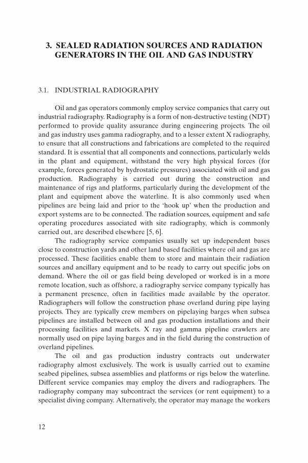
Oil and gas operators commonly employ service companies that carry outindustrial radiography. Radiography is a form of non-destructive testing (NDT)performed to provide quality assurance during engineering projects. The oiland gas industry uses gamma radiography, and to a lesser extent X radiography,to ensure that all constructions and fabrications are completed to the requiredstandard. It is essential that all components and connections, particularly weldsin the plant and equipment, withstand the very high physical forces (forexample, forces generated by hydrostatic pressures) associated with oil and gasproduction. Radiography is carried out during the construction andmaintenance of rigs and platforms, particularly during the development of theplant and equipment above the waterline. It is also commonly used whenpipelines are being laid and prior to the ‘hook up’ when the production andexport systems are to be connected. The radiation sources, equipment and safeoperating procedures associated with site radiography, which is commonlycarried out, are described elsewhere [5, 6].
The radiography service companies usually set up independent basesclose to construction yards and other land based facilities where oil and gas areprocessed. These facilities enable them to store and maintain their radiationsources and ancillary equipment and to be ready to carry out specific jobs ondemand. Where the oil or gas field being developed or worked is in a moreremote location, such as offshore, a radiography service company typically hasa permanent presence, often in facilities made available by the operator.Radiographers will follow the construction phase overland during pipe layingprojects. They are typically crew members on pipelaying barges when subseapipelines are installed between oil and gas production installations and theirprocessing facilities and markets. X ray and gamma pipeline crawlers arenormally used on pipe laying barges and in the field during the construction ofoverland pipelines.
The oil and gas production industry contracts out underwaterradiography almost exclusively. The work is usually carried out to examineseabed pipelines, subsea assemblies and platforms or rigs below the waterline.Different service companies may employ the divers and radiographers. Theradiography company may subcontract the services (or rent equipment) to aspecialist diving company. Alternatively, the operator may manage the workers
12

directly. These approaches demand close supervision and co-operation fromthe separate service companies that specialize in diving and radiography.
3.2. INSTALLED GAUGES
‘Nuclear (or nucleonic) gauges’ are installed extensively on plant andequipment associated with the oil and gas industry [7]. Each gauge usuallycomprises one or more radioactive sources associated with at least oneradiation detector. Typically, 137Cs sources are used with activities of up to5 GBq and occasionally up to 100 GBq, depending on the physical dimensionsof the plant and the purpose of the gauge. The gauges are normally installed ina transmission mode (rather than a backscatter mode), meaning that theradiation penetrates the medium but is attenuated to a measurable extentbefore it reaches the detector. The source usually remains installed in a steel orlead housing of about 30 cm in diameter, fixed to the side of the vessel orpipeline; the radiation detectors are mounted diametrically opposite the sourcehousing on the wall of the vessel or pipeline (Fig. 5). The radiation intensity atthe detector depends on the density of the contents of the vessel or pipeline.More penetrating gamma radiation from a 60Co source is needed for the vesselsof largest diameter or greatest wall thickness or for denser media contained in
FIG. 5. Installed density gauge (courtesy: National Radiological Protection Board, UK).
13
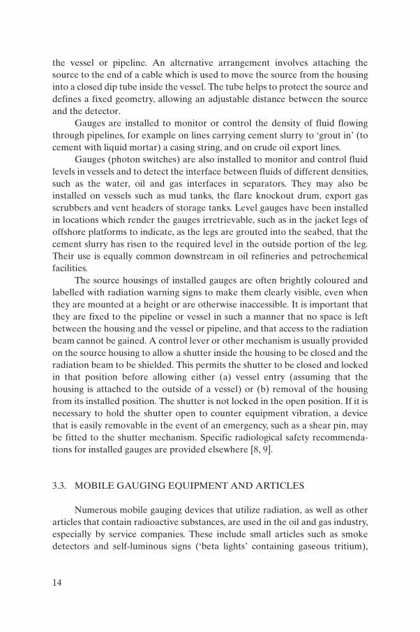
the vessel or pipeline. An alternative arrangement involves attaching thesource to the end of a cable which is used to move the source from the housinginto a closed dip tube inside the vessel. The tube helps to protect the source anddefines a fixed geometry, allowing an adjustable distance between the sourceand the detector.
Gauges are installed to monitor or control the density of fluid flowingthrough pipelines, for example on lines carrying cement slurry to ‘grout in’ (tocement with liquid mortar) a casing string, and on crude oil export lines.
Gauges (photon switches) are also installed to monitor and control fluidlevels in vessels and to detect the interface between fluids of different densities,such as the water, oil and gas interfaces in separators. They may also beinstalled on vessels such as mud tanks, the flare knockout drum, export gasscrubbers and vent headers of storage tanks. Level gauges have been installedin locations which render the gauges irretrievable, such as in the jacket legs ofoffshore platforms to indicate, as the legs are grouted into the seabed, that thecement slurry has risen to the required level in the outside portion of the leg.Their use is equally common downstream in oil refineries and petrochemicalfacilities.
The source housings of installed gauges are often brightly coloured andlabelled with radiation warning signs to make them clearly visible, even whenthey are mounted at a height or are otherwise inaccessible. It is important thatthey are fixed to the pipeline or vessel in such a manner that no space is leftbetween the housing and the vessel or pipeline, and that access to the radiationbeam cannot be gained. A control lever or other mechanism is usually providedon the source housing to allow a shutter inside the housing to be closed and theradiation beam to be shielded. This permits the shutter to be closed and lockedin that position before allowing either (a) vessel entry (assuming that thehousing is attached to the outside of a vessel) or (b) removal of the housingfrom its installed position. The shutter is not locked in the open position. If it isnecessary to hold the shutter open to counter equipment vibration, a devicethat is easily removable in the event of an emergency, such as a shear pin, maybe fitted to the shutter mechanism. Specific radiological safety recommenda-tions for installed gauges are provided elsewhere [8, 9].
3.3. MOBILE GAUGING EQUIPMENT AND ARTICLES
Numerous mobile gauging devices that utilize radiation, as well as otherarticles that contain radioactive substances, are used in the oil and gas industry,especially by service companies. These include small articles such as smokedetectors and self-luminous signs (‘beta lights’ containing gaseous tritium),
14

hand-held testing instruments, and larger pieces of equipment intendedprimarily for use only at service companies’ bases.
Fire protection equipment service companies commonly use hand-heldlevel gauges to determine the fluid level in fire extinguisher bottles andcylinders. Attached to the same long handle are two short probes, onecontaining a 137Cs source of several megabecquerels and the other a radiationdetector (Fig. 6). As the probes are moved up either side of an extinguisherbottle a signal from the detector provides a reading on a meter. The level offluid is indicated when the detector indicates a change in the intensity ofattenuated radiation. A similar hand-held probe containing a 241Am–Be sourceis used primarily by NDT service companies to detect water trapped betweenthe lagging (insulation) and the insulated surface of a pipe or vessel. Fast (highenergy) neutrons emitted by the source are ‘thermalized’ (reduced in energy)and scattered back to a detector in the probe if water is trapped behind thelagging. Water discovered using this procedure can then be released before itcauses corrosion which would weaken the pipe.
The pipe wall profiler is an example of the larger sized equipment. Itcontains a 137Cs source of several gigabecquerels and a detector mounted on anannulus and is used to check the wall thickness and uniformity of steel pipes
FIG. 6. Mobile gauge for detecting the level of liquids in closed fire extinguishercylinders (courtesy: National Radiological Protection Board, UK).
15
intended for use in tubing strings. The annulus revolves at high speed aroundthe axis of each pipe while the pipe is moved through the centre of the annulus.The service company issues certificates to indicate that the tubes are of anappropriate standard to be used in the high temperature and pressureenvironment of an oil or gas well.
Mobile level gauge systems incorporating appropriate sealed radiationsources are commonly used to determine the height of a fluid level or aninterface between different fluids. One such investigation is carried out onoffshore platforms to determine the level of potentially corrosive water ingressinto the subsea sections of flooded members. The gauging system is eithermanipulated by divers or attached to the remotely operated vehicle ofa miniature submarine. Other examples of usage include: detection of liquidlevels in storage containers, still bases, reactors and transport tankers; checkingfor blockages caused by solid deposits and accumulations on internal pipewalls; and determination of the location of a vessel’s internal structures such aspacking levels in absorption towers and catalyst beds in reactors. For example,a reactor vessel at a petrochemical site could be investigated using a gammatransmission gauge that shows that the catalyst has been spent and that thepacked beds have expanded, thereby narrowing the vertical separationbetween adjacent beds. The results may help the plant management to decidewhen to regenerate the catalyst. This density profiling is most often used toinvestigate distillation columns [10]. The vapour spaces are clearly differen-tiated on the basis of the relatively high levels of radiation attenuation detectedas the source or detector descends past the levels of the tray structures.Reference scans (when the columns are operating normally) and blank scans(when the columns are empty) permit the detection not only of flooding,foaming and missing or collapsed trays, but also of more subtle faults such as ahigh liquid level on the trays and high vapour density. It is also possible toquantify more accurately the foam densities forming in different parts of thecolumn. By using a fast neutron (e.g. 241Am–Be) source to scan down the sideof a vessel, it is possible to detect phase changes of hydrogenous substances, forexample, to determine water, oil and vapour interfaces [11]. Neutron sourcesare used to monitor flare stack lines for ice deposits that start to form whencondensates freeze in very cold weather and thereby create a potential flarestack hazard.
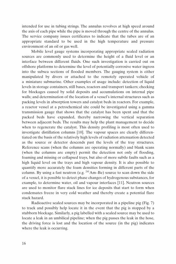
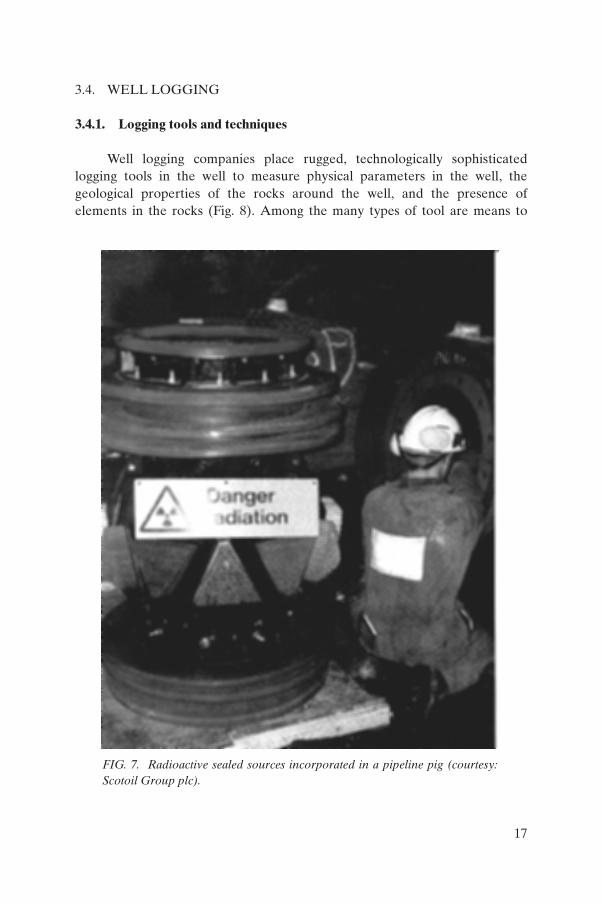
Radioactive sealed sources may be incorporated in a pipeline pig (Fig. 7)to track and possibly help locate it in the event that the pig is stopped by astubborn blockage. Similarly, a pig labelled with a sealed source may be used tolocate a leak in an umbilical pipeline; when the pig passes the leak in the hose,the driving force is lost and the location of the source (in the pig) indicateswhere the leak is occurring.
16
3.4. WELL LOGGING
3.4.1. Logging tools and techniques
Well logging companies place rugged, technologically sophisticatedlogging tools in the well to measure physical parameters in the well, thegeological properties of the rocks around the well, and the presence ofelements in the rocks (Fig. 8). Among the many types of tool are means to
FIG. 7. Radioactive sealed sources incorporated in a pipeline pig (courtesy:Scotoil Group plc).
17
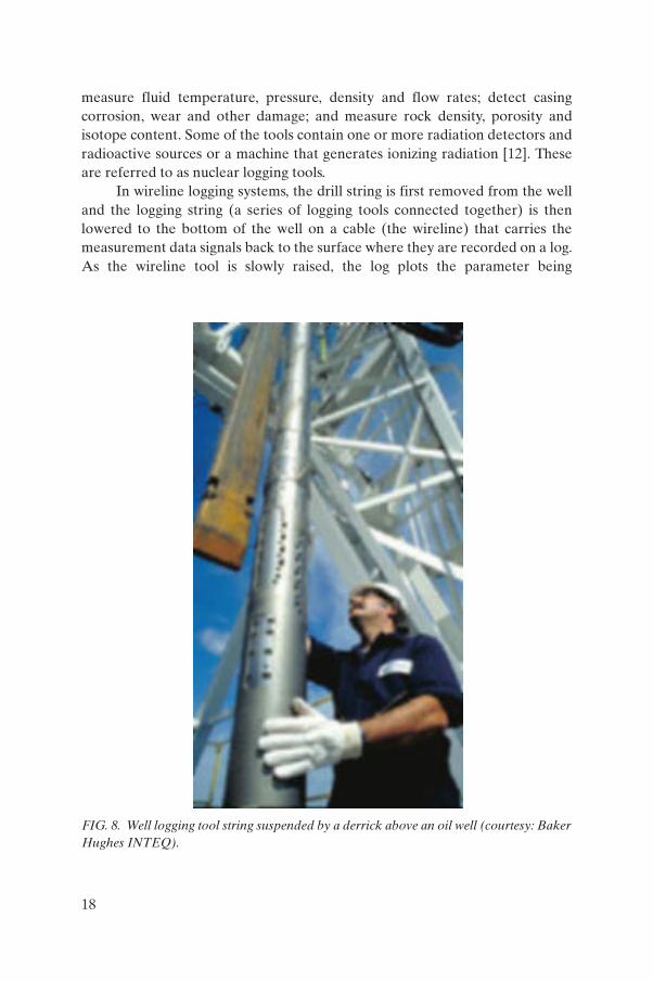
measure fluid temperature, pressure, density and flow rates; detect casingcorrosion, wear and other damage; and measure rock density, porosity andisotope content. Some of the tools contain one or more radiation detectors andradioactive sources or a machine that generates ionizing radiation [12]. Theseare referred to as nuclear logging tools.
In wireline logging systems, the drill string is first removed from the welland the logging string (a series of logging tools connected together) is thenlowered to the bottom of the well on a cable (the wireline) that carries themeasurement data signals back to the surface where they are recorded on a log.As the wireline tool is slowly raised, the log plots the parameter being
FIG. 8. Well logging tool string suspended by a derrick above an oil well (courtesy: BakerHughes INTEQ).
18

measured against the depth. ‘Logging-while-drilling’ and ‘measurement-while-drilling’ systems avoid the need to first remove the drill string by incorporatingthe logging tools in the drill collar or in coiled tubing. Signals are sent back tothe surface by means of a positive ‘mudpulse’ telemetry system [13]. Equip-ment at the wellhead interprets the mud pulses and logs the data.
There are four common nuclear logging techniques:
(1) The first, sometimes called the gamma measurement technique (differentlogging companies may use brand names), simply measures and identifiesthe gamma rays emitted by naturally occurring radionuclides in rocks tohelp distinguish the shale content of sedimentary rocks and aid litho-logical identification. The log records the uranium, thorium andpotassium content of the rocks.
(2) The second technique, which provides a neutron–neutron or compen-sated neutron log, demands a radioactive source of up to several hundredgigabecquerels of 241Am–Be or Pu–Be in the tool to emit 4–5 MeVneutrons. An elongated skid hydraulically presses the tool against thewall of the well and two radiation detectors, located at different distancesfrom the source in the tool, measure the neutrons backscattered by therock formation. The relationship between the two readings provides aporosity index for the rock. This indicates how porous the rock is andwhether it is likely to contain hydrocarbons or water.
(3) The third technique uses a tool, the gamma–gamma or density tool, whichcontains two detectors and a 137Cs source, usually of up to 75 GBq. Theamount of gamma backscatter from the formation provides the densitylog that, together with the porosity log, is a valuable indicator of thepresence of gas. A brand name may refer to this technique.
(4) The fourth technique, termed neutron–gamma logging, employs a toolthat houses a miniature linear accelerator. It contains up to severalhundred gigabecquerels of tritium (3H), a very low energy beta particleemitter. When a high voltage (typically 80 kV) is applied to the device, itaccelerates deuterium atoms (2H) that bombard the tritium target andgenerate a large number of very high energy (14–15 MeV) neutrons inpulses lasting a few microseconds. Certain nuclides become radioactivewhen hit by this neutron flux, and their subsequent radioactive decaywithin the next few milliseconds can be monitored when the process isrepeated a great number of times per second. Either the gamma radiationemitted as the activated atoms decay or the thermal neutron decaycharacteristics are measured to identify the activated species of atoms[14]. The chlorine or salt water content of the rocks is of particularinterest. A brand name may refer to this technique.
19

The gamma and neutron sources used in these tools are normallytransported in separate heavy containers termed shipping shields or carryingshields. They are Type A transport packages (or sometimes Type B for theneutron source) that meet the specifications for Category III labelling asdefined by the IAEA Regulations for the Safe Transport of RadioactiveMaterial [15]. They may be transported by road in the vehicles of the loggingcompanies (Fig. 9) to the land well. When they are to be used offshore, theshields are usually contained in an overpack [15]. This may be a large thick-walled box (external dimensions about 1.75 m × 1.75 m × 1.75 m) that alsoserves as a storage container at the well site (Fig. 10). The shields do notprovide adequate shielding to allow storage of the sources without use of thelarge container. When the tools are hoisted into position above the well, thelogging engineer transfers the sources from the shields to the tools using ahandling rod approximately 1.5 m long (Fig. 11). The dose rates of the 137Cssource are significant [16, 17] but not normally isotropic owing to theconstruction of the source assembly. Dose rates may exceed 7.5 µSv/h for up to30 m in the forward direction and about 4 m behind the engineer. The radiationfrom the source is directed away from any occupied areas. The dose rates of theneutron sources can exceed 7.5 µSv/h for distances of up to about 4 m. In
FIG. 9. Radioactive source being transported by road (courtesy: National RadiologicalProtection Board, UK).
20
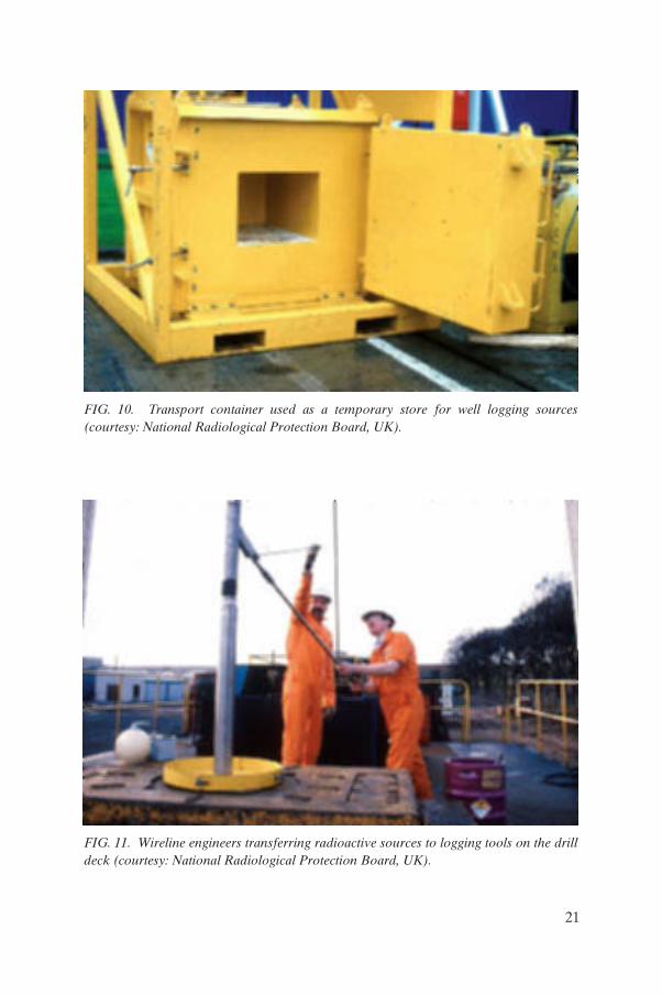
FIG. 10. Transport container used as a temporary store for well logging sources(courtesy: National Radiological Protection Board, UK).
FIG. 11. Wireline engineers transferring radioactive sources to logging tools on the drilldeck (courtesy: National Radiological Protection Board, UK).
21

addition to a ‘set’ of sources used in the logging tools, the logging engineer willneed a number of field calibration sources to carry out final checks on the toolsbefore beginning the log. Master calibrations are periodically performed on thetools at the logging company’s operations base. These tests will involve puttingthe sources into the tools or into a section of the tool (Fig. 12) and eitherplacing the tool inside a calibration block or placing a block over the sourceposition on the tool. The master calibration for the neutron–gamma loggingtool involves generating neutrons while the tool is inside a tank filled with asuitable fluid (for example, clean water). The tank and its contents remainradioactive for a short time (up to 30 min) after the tool has been switched off(Fig. 13).
The instrument technicians assigned to the service company’s base willuse a range of sources of relatively low activity to aid in adjusting the settings ofthe radiation detectors (Fig. 14).
The logging tools and the sources they contain are subjected to very highdownhole temperatures and pressures. The sources normally fall within thedefinition of ‘special form radioactive material’ as sealed sources satisfying thetest criteria specified by the IAEA [15] and ISO standards [18]. Nevertheless,the sources are normally given the further protection of a special container (apressure vessel) whenever they are in the shield or logging tool. The sources
FIG. 12. Wireline engineer using a handling tool to transfer a radioactive source during acalibration procedure (courtesy: National Radiological Protection Board, UK).
22
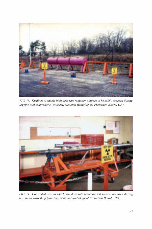
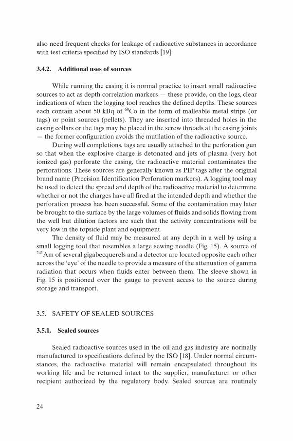
FIG. 13. Facilities to enable high dose rate radiation sources to be safely exposed duringlogging tool calibrations (courtesy: National Radiological Protection Board, UK).
FIG. 14. Controlled area in which low dose rate radiation test sources are used duringtests in the workshop (courtesy: National Radiological Protection Board, UK).
23
also need frequent checks for leakage of radioactive substances in accordancewith test criteria specified by ISO standards [19].
3.4.2. Additional uses of sources
While running the casing it is normal practice to insert small radioactivesources to act as depth correlation markers — these provide, on the logs, clearindications of when the logging tool reaches the defined depths. These sourceseach contain about 50 kBq of 60Co in the form of malleable metal strips (ortags) or point sources (pellets). They are inserted into threaded holes in thecasing collars or the tags may be placed in the screw threads at the casing joints— the former configuration avoids the mutilation of the radioactive source.
During well completions, tags are usually attached to the perforation gunso that when the explosive charge is detonated and jets of plasma (very hotionized gas) perforate the casing, the radioactive material contaminates theperforations. These sources are generally known as PIP tags after the originalbrand name (Precision Identification Perforation markers). A logging tool maybe used to detect the spread and depth of the radioactive material to determinewhether or not the charges have all fired at the intended depth and whether theperforation process has been successful. Some of the contamination may laterbe brought to the surface by the large volumes of fluids and solids flowing fromthe well but dilution factors are such that the activity concentrations will bevery low in the topside plant and equipment.
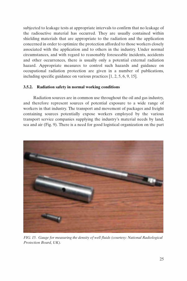
The density of fluid may be measured at any depth in a well by using asmall logging tool that resembles a large sewing needle (Fig. 15). A source of241Am of several gigabecquerels and a detector are located opposite each otheracross the ‘eye’ of the needle to provide a measure of the attenuation of gammaradiation that occurs when fluids enter between them. The sleeve shown inFig. 15 is positioned over the gauge to prevent access to the source duringstorage and transport.
3.5. SAFETY OF SEALED SOURCES
3.5.1. Sealed sources
Sealed radioactive sources used in the oil and gas industry are normallymanufactured to specifications defined by the ISO [18]. Under normal circum-stances, the radioactive material will remain encapsulated throughout itsworking life and be returned intact to the supplier, manufacturer or otherrecipient authorized by the regulatory body. Sealed sources are routinely
24
subjected to leakage tests at appropriate intervals to confirm that no leakage ofthe radioactive material has occurred. They are usually contained withinshielding materials that are appropriate to the radiation and the applicationconcerned in order to optimize the protection afforded to those workers closelyassociated with the application and to others in the industry. Under normalcircumstances, and with regard to reasonably foreseeable incidents, accidentsand other occurrences, there is usually only a potential external radiationhazard. Appropriate measures to control such hazards and guidance onoccupational radiation protection are given in a number of publications,including specific guidance on various practices [1, 2, 5, 6, 9, 15].
3.5.2. Radiation safety in normal working conditions
Radiation sources are in common use throughout the oil and gas industry,and therefore represent sources of potential exposure to a wide range ofworkers in that industry. The transport and movement of packages and freightcontaining sources potentially expose workers employed by the varioustransport service companies supplying the industry’s material needs by land,sea and air (Fig. 9). There is a need for good logistical organization on the part
FIG. 15. Gauge for measuring the density of well fluids (courtesy: National RadiologicalProtection Board, UK).
25

of the operator to ensure that the sources and the workers trained to use orinstall them are mobilized to arrive in a co-ordinated manner. The industry isaccustomed to good communications, ensuring that consignors and consigneesare fully aware of the sources’ movements and in-transit storage locations.Temporary and permanent storage arrangements made available for thesources on their arrival must meet standards that satisfy the responsibleregulatory body (Fig. 16). These standards are likely to include requirementsfor security; intelligible warnings in local or multiple languages; adequateshielding; and separate storage away from other hazards, other (non-radio-active) materials, and workplaces.
Work that includes the removal of radiation sources from shieldedcontainers, particularly those manipulated during radiography and welllogging, normally demands the use of barriers (Fig. 17) to designate the extentof the controlled areas [1]. This presents a problem where space is limited, suchas on offshore production platforms, and where the work must be carried out ata specific location, such as the radiographic examination of items in situ andwell logging on the drill floor. Oil and gas production is almost continuous(except during shutdowns and workovers) and at isolated drill sites personnelwill normally remain nearby even when they are off duty. Constraints need to
FIG. 16. Store for radioactive sources (courtesy: National Radiological ProtectionBoard, UK).
26

be imposed on the radiography consistent with those of the workingenvironment. One possibility would be to limit the source activity to anappropriate value, for example 1 TBq of 192Ir, depending on the extent of theworksite and any controlled areas designated while the work is in progress. Thismay result in a need to tolerate longer film exposure times and a reduced rateof radiograph production. Best use needs to be made of places that are furthestfrom normally occupied areas, for example, by moving items to be radio-graphed on offshore platforms to the lowest level (the cellar deck) wherefeasible. The walls, floors and ceilings on offshore platforms/rigs may notprovide enough shielding to reduce the dose rates to acceptable values insurrounding areas. The use of shielding placed near the source and the carryingout of the work in the vicinity of topside plant, such as storage tanks andvessels, that provides shielding will minimize the extent of controlled areas. It isimportant to provide good beam collimation, enabling beams produced duringradiography and well logging to be directed away from occupied areas, and toadhere to appropriate procedures.
Warning methods such as public announcements, audible signals (forexample, a portable air horn) and visible signals (for example, a flashing light inthe vicinity of the work) help restrict access to controlled areas.
FIG. 17. Chain barriers designating a controlled area on the drill floor while loggingsources are in use (courtesy: National Radiological Protection Board, UK).
27

3.5.3. High exposure and overexposure to radiation sources
Without suitable radiation protection measures, radiographic and welllogging radiation sources could give rise to significant external doses,particularly while they are being manipulated routinely out of their shieldedcontainers. If appropriate action is not taken when, for instance, a typical radio-graphic source fails to return to the exposure container, a dose approaching orexceeding a regulatory limit could be received within minutes of exposure [20].Improper handling of well logging sources and emergency situations such asextended exposure arising during a difficult removal of a source from thelogging tool could result in significant doses being received by the engineer andtechnicians carrying out this type of work. The most likely cause of a significantdose being accidentally received is the failure to use a suitable radiationmonitoring instrument to detect an unshielded source. When site radiographyand well logging are carried out it is always necessary to have available theexpertise and necessary equipment (such as remote handling tongs) toimplement contingency plans quickly and efficiently. On offshore oil and gasplatforms it may not be practicable to evacuate personnel to a safe area and itis therefore more urgent to implement source recovery.
Installed gauges and most mobile gauging devices are unlikely to containradiation sources capable, under normal circumstances, of delivering dosesequivalent to a dose limit. Care is needed by the operator not to allow access toa vessel on which a source housing is mounted until the radiation beam hasbeen sufficiently shielded by a shutter within the housing that is locked in theclosed position. This is particularly important where dip tube or suspendedsource configurations are used within the vessel. Radiation monitoring must becarried out to confirm that the shutters have actually closed and that it is safe toenter a vessel or to manipulate a gauge source housing.
Significant exposure to radiation could result from improper handling ofgauge sources if, for example, maintenance or leakage testing were to becarried out incorrectly. Significant exposure could also result from high outputdevices such as neutron generators if they were to be energized before loweringdownhole or before providing adequate shielding by means of a calibrationtank.
3.5.4. Lost or misplaced sources
Radiation sources used in the oil and gas industry are frequentlytransported between service company bases and points of use (Fig. 9); they aresometimes transferred or redirected to new locations and may be moved,removed for temporary storage or reallocated within a field or between sites.
28

They are vulnerable to loss or theft or simply to being misplaced. Servicecompanies and operators must keep detailed and accurate records to accountfor the whereabouts of sources at all times (see example documentation,Fig. 18) so as to prevent accidental occupational exposure or unauthorizeddisposal. For sources used on offshore platforms and rigs, the keeping of anup-to-date record at an appropriate onshore location would aid recovery of thesources in the event of a serious incident. The likelihood of loss or damage isgreater for portable or mobile sources (particularly small items such as smokedetectors and beta lights). Installed equipment is to be detailed on plant andequipment drawings. Every effort must be made to locate radiation sourcesthat are not accounted for and the regulatory body must be notified promptlyof any loss. Sources that are lost or ‘orphaned’ present a radiological risk to thepublic and constitute a potentially serious hazard to any individual member ofthe public who attempts to remove a source from safe containment. They maybecome a significant economic burden and risk to the wider public if, forexample, they are recycled with scrap metal.
Unnecessary risks that may result in the loss of a source ought to beavoided; for example, it is desirable that source containers are not lifted overthe sea. When sources must be manipulated and where there is a risk of loss,suitable precautions need to be taken. A plate covering the annulus around awell logging tool, or a chain connecting the source to the handling rod while itis being inserted into the tool, is sufficient to prevent a disconnected sourcefrom falling into a well. A tarpaulin may be used to cover deck grating duringan emergency procedure to recover a disconnected source from the projectiontube of a radiographic exposure container.
3.5.5. Retrieval of disconnected sources from a well
When logging tools are placed in a well there is a risk that the radiationsources they contain, such as 137Cs and 241Am, may not be retrievable [21, 22].The wireline support for tools may break or the tool may become ‘snagged’within an open (uncased) hole. If any radioactive source associated with welllogging becomes stuck downhole, the licensee must immediately notify theregulatory body and advise the operator, ensuring that every reasonable effortis made to recover the source. Specialist service companies using specialequipment may be called upon to carry out ‘fishing’ operations to retrievedisconnected logging equipment. It is important that the manner in which therecovery is attempted does not compromise the integrity of the encapsulationof the radioactive material. Damage to the encapsulation could causewidespread radioactive contamination of the wellbore, drilling rig, fishing tools,
29

INST
AL
LA
TIO
N S
OU
RC
E R
EG
IST
ER
Det
ails
of a
ll ra
dioa
ctiv
e co
nsig
nmen
ts, t
hat i
s, s
eale
d so
urce
s an
d un
seal
ed s
ubst
ance
s ar
rivi
ng a
t and
dep
arti
ng fr
om th
e in
stal
lati
on s
houl
d be
re
cord
ed. U
se o
ne li
ne p
er c
onsi
gnm
ent.
Serv
ice
com
pany
Sour
cear
riva
lda
te
Nuc
lide
e.g.
192 Ir
Act
ivit
ye.
g. G
Bq,
Ci
Phy
sica
l for
me.
g. s
eale
d, g
as,
liqui
d, p
owde
r
Sour
cese
rial
num
ber
Stor
age
loca
tion
Sour
cedi
spos
alda
te
Dis
posa
l rou
te
e.g.
bea
ch, w
ell
num
ber,
rig
tran
sfer
A
udit
dat
e
FIG
. 18.
Exa
mpl
e of
a r
ecor
d to
acc
ount
for
radi
oact
ive
sour
ces.
30

mud tanks, mud pumps, and other equipment that comes into contact with thedrilling fluids. During fishing operations, the logging engineer provides adviceand monitors the mud returns for any evidence of damage to the source usinginstruments suitable for detecting the types and energies of the emissions fromthe radioactive source material. Any increase in radiation levels detected in thereturned fluids would call for the operator to stop recovery operations immedi-ately, pending an assessment to determine the source’s status. The specialistservice companies and the operator must advise the regulatory body whenfishing operations have been unsuccessful and obtain agreement to discontinuerecovery operations. Appropriate measures will be needed to ensure that anabandoned source in a tool is not destroyed in any future drilling of the well.Usually the tool is cemented in, possibly using coloured cement, and a hardmetal deflector may be placed on top of the cement plug. Later, drilling aroundthe plug may continue, with a permanent plaque attached at the wellhead toprovide details of the abandoned source and a clear warning.
3.5.6. Physical damage to sources, containers and other equipment
The containers in which radiation sources are transported, moved andstored are generally designed to provide adequate shielding and radiationsafety under most climatic conditions. They demand a degree of maintenancethat may need to be increased in more arduous working environments, forexample, in salty or sandy environments where corrosion and increased wearmay be of concern. Installed gauges often remain in position for long periods oftime and it is important that they are kept clean so that identification markings,labels or other safety markings — which some might consider to be cosmeticfeatures — do not become illegible. Otherwise, in the longer term, the obviousprofile, discernible relevant markings and even the source’s identity may belost. The care and maintenance of ancillary equipment for controlling theradiation source (tubes and cables used for radiography and handling rods usedfor well logging) are similarly very important.
Increased dose rates and unacceptable external exposures may result ifthe shielding of a radiation source container is damaged by mechanical,thermal or chemical means. Suitable precautions will normally include:
(a) Taking regular measurements of the shielding properties of radiationsource containers.
(b) Monitoring measured surface dose rates using control charts (seeexample documentation, Fig. 19); the charts are likely to indicate evensubtle deterioration in the standard of radiation safety.
31

Date of measurements . . . . . . . . . . . . . . . . . . . . .Instrument used: Gamma meter . . . . . . . . . . . . Neutron meter . . . . . . . . . . . .
Radioactive sources storage container results
µSv/h
µSv/h
µSv/h
µSv/h
µSv/hµSv/h
µSv/h
µSv/h
Controlled area results
ROTARYTABLE
DRILLFLOOR
µSv/h
µSv/h
µSv/h
µSv/h
µSv/h
UPPIPE DECK
‘V’ DOOR
RPO Signature . . . . . . . . . . . . . . . . . . . . .
FIG. 19. Example of a radiation survey form.
32

(c) Performing source leakage tests (smear tests) at intervals advised by thesource or equipment manufacturer or as required by the regulatory body;sources that are at greatest risk of rupture when placed downhole maydemand the most frequent testing, for example, biannually.
Sealed sources used in the oil and gas industry may become damaged orruptured to the extent that the radioactive material leaks or is released in looseform from the encapsulation. For instance, despite taking the necessaryprecautions there is always some risk of the integrity of the source encapsu-lation being compromised during attempts to retrieve a disconnected sourcefrom a well. Leakage may also result from mechanical, thermal or chemicalconditions exceeding the specifications of the source or from the unlikelysituation of poor quality control by the manufacturer or improper encapsu-lation of the sealed radioactive material. Sealed sources are leak tested aftermanufacture and before transport, and additional tests may be arranged asrequired by the end user or to meet the requirements of the regulatory body.
A ruptured industrial radiography source could create a severe,immediate health threat to individuals [20]. The most common radioactivematerials used, 192Ir and 60Co, are incorporated into sources with activitiesgenerally of several hundreds or thousands of gigabecquerels. Therefore, if theencapsulation becomes compromised, extensive contamination can result, withthe consequent potential for extremely large internal and external doses beingreceived by those exposed to the contamination.
To deal with an event involving the rupture of an industrial radiographyor well logging source (including the rupture, during recovery attempts, of awell logging source that has become lodged downhole), written emergencyprocedures that the licensee can implement in conjunction with the operator[23] need to be immediately available, including procedures for the:
(a) Immediate notification of the regulatory body by the licensee inconjunction with the operator.
(b) Securing of the affected area in order to limit the spread of contaminationand to prevent anyone from incurring either an internal or external doseas a result of being exposed to the ruptured source.
(c) Restriction of access until a person is authorized, by reason of trainingand experience, to assess the problem, including the extent of the contam-ination, and decide on further actions such as decontaminationprocedures. In the case of damage occurring while attempting to retrievea disconnected source from a well, the access restrictions apply to thearea around the wellhead and to any equipment used in the recoveryoperations.
33
(d) Retrieval of all contaminated items and their storage in such a way as toprevent further exposures and the spread of contamination, pending theirdecontamination to authorized clearance levels [24] or their disposal asradioactive waste in accordance with the requirements of the regulatorybody.
(e) Monitoring for internal contamination of those persons involved in theoperations that gave rise to the incident or who were in the immediatearea when the incident occurred, and assessment of the total, committedeffective doses resulting from the internal and external exposures ofthose persons [25, 26].
(f) Retention in the company records of the results of these assessments andthe copying of them to the companies that employ the workers involved.
General guidance is available on occupational radiation protection inintervention situations and emergencies [1].
If damage to a radiography source is identified in the early stages,widespread contamination can be avoided. A ruptured radiography source maybe returned to the shielded position in the exposure container, or otherwiseshielded to decrease the immediate health threat. Risks associated with adamaged radiography source can be further minimized by:
(a) Managing individuals who may be contaminated so that the contami-nation is contained within a controlled area;
(b) Decontaminating any person found to be contaminated, in accordancewith established procedures [27];
(c) Handling with care any potentially contaminated items, such as ancillaryradiographic equipment, and, if possible, placing them in bags to preventany spread of contamination;
(d) Setting up cordons to prevent access to the area concerned in the event ofthere being any doubt whether contamination exists but where there areelevated radiation readings;
(e) Treating any potentially contaminated item or area as contaminated untilan assessment can be completed, i.e. the exposure device, any materialused to shield the radioactive source, the area, and any equipment in theimmediate vicinity [23];
(f) Performing leak tests on the radiography sources as soon as possible afterany incident or other occurrence that could cause stress to the sourceencapsulation.
34

3.5.7. Site emergencies, natural disasters and strife
The highly combustible products of the oil and gas industry pose aconstant risk of fire and explosion. Hazardous chemicals and explosives arealso used routinely in the industry. The operator must minimize the possibilitiesof these non-radiation hazards compounding the risks associated with workinvolving radiation sources. Care is needed in storing hazardous materials toensure that there is adequate separation between the different stores and otherhazardous areas such as the wellhead.
Site emergency plans will need to include contingencies to deal with thepotential radiation exposure of firefighters and other personnel who need todeal with an incident, accident or other occurrence in an area where radiationsources are present. A contingency plan has to include standing instructions tospecialist service companies to make safe any radiation source for which theyare responsible in the event that a site emergency status is announced. Theoperator ensures that appropriate action will be taken either to make safe asource or to implement suitable countermeasures in the event that a radiationworker is incapacitated during the emergency.
It is important that equipment and radiation sources be secured againstdamage or loss in situations where natural disaster or strife is imminent.
3.6. WASTE MANAGEMENT OF SEALED SOURCES
3.6.1. Introduction
The proper management of spent and disused sources by the owner/operator is of particular importance since such sources may still containsignificant amounts of radioactive materials. If not properly managed, this typeof radioactive waste has the potential to present serious risks to human healthand to the environment. In many ways, the waste management of sealedsources is more easily facilitated than the management of unsealed sources andNORM wastes owing to their physical form and structure (i.e. contained) andincorporated safety features. A radioactive waste management programmeapplicable to sealed sources has to be documented and submitted to theregulatory body for review and approval. General guidance on the componentsand structure of such a programme is given in Refs [28, 29]. The most importantaspects of the waste management programme are described in Sections 3.6.2. to3.6.8.
35
3.6.2. Waste minimization strategies
The development of strategies to minimize waste generation is given ahigh priority in the waste management programme. Some degree of wasteminimization with regard to sealed sources can be achieved through:
(a) The use of relatively short lived radionuclides where possible;(b) The use of the minimum quantity of radioactive material consistent with
achieving the objective of the work application;(c) Ensuring that sources are not physically damaged;(d) Routine monitoring for source leakage (to minimize contamination of
other items);(e) Reuse of sealed sources and ancillary equipment, e.g. shielding
containers;(f) Recycling by the manufacturer.
On-site decay storage is the preferred method of waste minimization inthe case of short lived radionuclides (half-life <100–200 d), e.g. 192Ir.
3.6.3. Waste inventories and characterization
A detailed waste inventory is maintained which includes details of:
(a) Source type, radionuclide and activity;(b) All sources removed from regulatory control; (c) All sources transferred to other facilities, e.g. manufacturer, storage,
disposal.
Waste characterization information can be obtained from the manufac-turer of the source.
3.6.4. Waste storage facilities
Suitable on-site storage areas are needed for spent and disused sourcesand for sources undergoing decay storage. Aspects to consider in the design ofsuch facilities include:
(a) Physical security,(b) Access controls,(c) Handling systems and other operational aspects,(d) Gamma dose rates on the exterior of the facility.
36

3.6.5. Predisposal management of radioactive waste
The predisposal management of radioactive waste may include a numberof processing steps covering pretreatment, treatment and conditioning as wellas storage and handling operations and transport prior to disposal. In the caseof sealed sources used in the oil and gas industry, the options are generallylimited to decay storage and transport to a centralized conditioning, interimstorage or disposal facility.
3.6.6. Disposal methods
The preferred disposal option is that contractual arrangements be madewhen purchasing sealed sources which allow for their return to the manu-facturer following use. This is particularly important in the case of high activitysources that cannot be removed from regulatory control until after many yearsof decay storage, or for sources containing long lived radionuclides. Long livedsources are generally conditioned by means of encapsulation in welded steelcapsules.
An alternative would be to transfer the sources to a waste management ordisposal facility authorized by the regulatory body. If no disposal facility isavailable the operator should make provision for the safe, long term storage ofspent and disused sources, preferably at a centralized storage facility approvedby the regulatory body. The storage facility must:
(a) Ensure isolation;(b) Ensure protection of workers, the public and the environment; (c) Enable subsequent handling, movement, transport or disposal.
Sealed sources should never be subjected to compaction, shredding orincineration. Neither should they be removed from their containers nor thecontainers modified, as this can lead to the contamination of other items andareas.
3.6.7. Transport of radioactive waste
All waste must be packaged and transported in accordance with theIAEA Regulations for the Safe Transport of Radioactive Materials [15]. Wasteconsignments should be accompanied by the necessary waste inventory andwaste characterization information.
37
3.6.8. Record keeping and reporting
A suitable and comprehensive record keeping system is usually requiredfor radioactive waste management activities. The record system allows thetracing of waste from the point of generation through to its long term storageand/or disposal. It is the responsibility of the regulatory body to determine thereporting requirements of the owner/operator with regard to radioactivewastes. However, the owner or operator also has responsibilities, namely, toalways exercise a duty of care with respect to radioactive waste managementactivities and to have sufficient records to ensure that the waste management isperformed appropriately.
4. UNSEALED RADIOACTIVE SUBSTANCES IN THE OIL AND GAS INDUSTRY
4.1. RADIOTRACER AND MARKER STUDIES
4.1.1. Unsealed radioactive materials used as tracers and markers
The oil and gas industry uses unsealed radioactive solids (powder andgranular forms), liquids and gases to investigate or trace the movement of othermaterials, even within closed and sometimes inaccessible pipework and vessels[4, 7]. Most of these radiotracers can be detected and/or measured easily bytheir emissions. To achieve the objectives of a study, the physical form of theradiotracer is selected or manufactured so as to be consistent with the materialsto be studied and its decay characteristics need to be appropriate [30]. Typicalproperties of a physical radiotracer include:
(a) Capability to follow the material under investigation but not display thesame chemical behaviour as, or react with, other material in the systemunder investigation;
(b) Stability of form such that it will not degrade in the high temperatures,pressures or corrosive media into which it is introduced;
(c) Minimal radiotoxicity, i.e. dose per unit activity intake;(d) Half-life compatible with the investigation schedule so as to minimize
residual contamination in the system or product;(e) Suitable radiation emissions making it readily detectable;
38

(f) Initial activity that is as low as reasonably achievable (ALARA), takinginto account the radiotracer’s half-life, the anticipated activity at themeasurement locations and the detection limits of the techniquesemployed.
Alpha emitters are not easily detected and are generally unsuitable asradiotracers. Beta emitters, including 3H and 14C, may be used when it isfeasible to use sampling techniques to detect the presence of the radiotracer, orwhen changes in activity concentration can be used as indicators of theproperties of interest in the system. Gamma emitters, such as 46Sc, 140La, 56Mn,24Na, 124Sb, 192Ir, 99Tcm, 131I, 110Agm, 41Ar and 133Xe are used extensively becauseof the ease with which they can be identified and measured. They are readilytraced or followed by detectors placed outside the system. They allow the useof non-invasive procedures that involve minimal or no disruption toproduction.
4.1.2. Examples of the upstream use of radiotracers and markers
Radiotracers are used during completion, stimulation and recoveryenhancements to determine that procedures have been carried out satisfac-torily. Some examples are described below.
As cement is mixed for a well completion, a glass ampoule, containingscandium oxide incorporating 750 MBq of 46Sc as powdered glass, is releasedinto the slurry tank just before the initial batch of cement is to be pumpeddownhole. By releasing the radioactive material directly into the cement, thecontamination of equipment and the risk of spillage are minimized. The tank ismonitored as the slurry is pumped to the bottom of the string and the groutrises to fill the annulus. As pumping continues, a logging tool is lowered downthe well through the displacement fluid to detect and monitor the progress ofthe plug of radiotracer rising up the annulus until its appropriate position isreached.
To evaluate whether a fracturing process to stimulate the flow haspenetrated rocks in the pay zone, plastic pellets coated with approximately10 GBq of 110Agm are added to a proppant during the ‘frac job’. When thefracturing work is complete and when surplus fluids have been removed fromthe well so as to prevent their solidification in the tubing string, the job isassessed by lowering a logging tool down the well to detect and map out themovement and final positions of the injection fluids and proppants.
To indicate the flow rate of the well fluids, radiotracer ‘spikes’,comprising 99Tcm and 131I solutions, are released from logging tools intoproduction wells and the time taken for them to traverse the known distance
39

between two radiation detectors is determined. When radiotracers are injectedalong with waterflood and gas drives, it is possible to identify the flow patterns,‘thief’ zones, channelling, flow rates of injected fluids in the reservoir and therelationship(s) between injector and producer wells. The activities of thenuclides injected are significant (Fig. 20) — up to 1 TBq of 3H and 14C labelledcompounds — but the activity concentrations of samples obtained at theproducer wells are very low.
In order to aid the detection of any spillage of solutions of these ‘soft’beta emitters, they are sometimes spiked with a short half-life gamma emittersuch as 82Br, which will need measures to minimize external exposures at theinjection well. ‘Hard’ beta emitters, such as the gaseous radiotracer 85Kr,generate bremsstrahlung and also need measures to minimize externalexposures.
FIG. 20. Tritiated water for injection as a radioactive tracer (courtesy:Scotoil Group plc).
40

4.1.3. Examples of the downstream use of radiotracers and markers
Flow rate measurement is one of the most common applications ofradiotracers. It is used to calibrate installed flow rate meters, measure theefficiency of pumps and turbines, investigate flow maldistribution and heattransfer problems and make plant or unit mass balances. The two methods inwidest use rely on pulse velocity and dilution flow measurements.
The pulse velocity method [31] relies on the injection of a sharp pulse orspike of gamma emitter into the process stream. The flow needs to be turbulentand completely fill the pipe bore. Downstream, at a distance sufficient toensure a good lateral mixing of the radiotracer with the process stream, tworadiation detectors are positioned, separated by an accurately measureddistance (L). As the radiotracer passes, the response of each detector isregistered and the mean transit time (T) measured. Knowing the mean internalcross-sectional area (A) of the pipe bore, the mean linear flow velocity (L/T)can be calculated and converted to volume flow rate (V=LA/T).
The dilution flow method does not need the flow to be full bore or beconfined within a closed circuit [32]; the flow can be in open channels, ditches,sewers or rivers. A known activity concentration (C) of radiotracer isintroduced at a known constant rate (U). Downstream, at a distance that allowscomplete lateral mixing, samples are taken and the activity concentration (S)measured. The volume flow rate (V) is very much greater than the injectionrate (U) and may be calculated (V=CU/S).
Often, a leak may be inferred from flow rate measurements. In othercircumstances, leaks may be detected directly, for example, when radiotracerseeps from a pipeline either above or below ground level.
Residence time measurements have also served to detect leaks acrossfeed–effluent exchangers associated with catalytic reactors. A radiotracer isinjected at the inlet of the vessel and a detector provides a signal to record thetime of its entry. Another detector at the vessel outlet is used to measure theinstantaneous concentration of tracer leaving the vessel. The response or ‘Ccurve’ of this detector represents the residence time distribution of material inthe vessel. A long residence time indicates excellent mixing in the vessel and ashort residence time indicates poor mixing (plug flow). The presence of asubsidiary peak prior to the main peak in the residence time distribution curvemay indicate a leak across the exchanger. Mean residence time of materials inchemical process vessels and the distribution of residence times both influencethe output and quality of the product. Analysis of C curves provides quanti-tative information relevant to the design of mixing characteristics of full sizeplant.
41
4.2. SAFETY OF UNSEALED RADIOACTIVE MATERIALS
4.2.1. Preparation of radiotracers
The radiotracers obtained from the isotope production facility may besuitable for use directly or may need to be prepared in a laboratory that theregulatory body has licensed to process the radioactive materials. Preparationmight include ‘labelling’ or tagging the non-active substrates such as glass orplastic beads of known mesh size with radioactive material. The laboratory maybake the radioactive material onto the bead surfaces or otherwise incorporatethe radioactive material into the beads. Alternatively, the radioactive materialmight be supplied in a suitable form, such as a coarse radioactive glass or sand,and the laboratory will simply dispense a known aliquot of the radioactivematerial. The preparation is intended to help minimize the handling andcomplexity of manipulations at the site where the radiotracer is introduced intothe system being investigated. The licensee must implement special proceduresto minimize dispersal, surface contamination and/or airborne contaminationfrom liquids, powdered solids and gases.
The laboratory will need appropriate facilities, including controlled areasfor handling open radioactive material, and be able to deal with potentialcontamination arising through routine handling or more serious spills.Engineered controls, such as a hood or an extract ventilation system, willprevent the dispersal, ingestion or inhalation of radioactive material. Amonitoring programme needs to include provision for conducting surfacecontamination measurements and dose rate surveys, airborne contaminationmeasurements and personnel monitoring for external and internal doses[25, 26].
The laboratory will package the radiotracer for transport to the site. It ispreferable that the design of the package and packaging be such that theradiotracer is ready for immediate application at the site. The design and anycontamination on internal and external surfaces of the package must satisfyspecifications and limits defined by the regulatory body. As consignor, thelaboratory must be conversant with labelling and documentation required forthe transport package(s).
4.2.2. Work with radiotracers
The operator will normally employ an injection company specializing intracer techniques to be the end user of the radiotracer. The operator or the enduser as required by the regulatory body will obtain a licence to carry out thework. The regulatory body will require a licence application to be accompanied
42
by sufficient details of the radiotracer to be used, the intended radiationprotection and operation procedures, sampling intentions if appropriate andproposals to deal with the radioactive waste expected to arise.
The injection company will prepare the well site or job site appropriatelyfor handling and processing unsealed radioactive material for normal workingand to mitigate the consequences of any incident that might occur. Usually thework will be carried out under circumstances that are much less ideal than inthe laboratory. However, the same radiation protection principles can beapplied. The injection company provides:
(a) Adequate containment for actual and potential contamination;(b) Suitable equipment, including personal protective equipment (including
respiratory protection as appropriate) and monitoring instruments; (c) Washing facilities and arrangements for good industrial hygiene
measures.
Suitable preparation and adherence to predefined procedures will notonly minimize the possibility of environmental contamination but will alsoreduce the risk of external and internal exposure to radiation workers and toother persons in the vicinity. These procedures include carrying out a survey todetermine background conditions prior to the start of any operations by theinjection company and the establishment of a controlled area around the workarea to prevent unauthorized persons from entering the area and beingexposed to radiation or becoming contaminated with the radioactive material.Controlled areas, where there is a significant risk that the radiotracer materialcould be spilled, are arranged so as to contain any such spillage. All relevantexposure pathways must be considered, including the inhalation of volatilesubstances such as 131I. The risk of inhalation can be minimized or eliminatedby using alternative non-volatile radionuclides such as 99Tcm instead of 131I.
When the radiotracer is to be injected into a high pressure system(Fig. 21), it is particularly important that the service company use suitable valvesystems and operating procedures to minimize the possibility of contamination,for example, checking that connections are tight before injecting theradiotracer. An experienced injection company will be aware of, and preparefor, the problems that may occur, such as a ‘sand-out’. This occurs when thepressure in the wellbore causes the backward flow of fluids to the surface.When a radiotracer has been injected into a well, a sand-out can result insurface contamination around the wellhead. The injection company isresponsible for decontaminating any area or equipment that is contaminated asa result of the operations. This includes ancillary items not owned by theinjection company, such as mixing vessels, flow lines, tubing and any other
43

equipment contaminated by the radioactive material. The decontaminationmust reduce residual contamination to agreed clearance levels acceptable tothe regulatory body. The injection company must carry out surveys todemonstrate that any equipment that has been contaminated by radiotracer,but which will not remain under the control of the licensee, satisfies release
FIG. 21. Radioactive gas being injected at high pressure for use as a tracer(courtesy: Scotoil Group plc).
44

requirements accepted by the regulatory body. Records of the contaminationsurvey results must be copied to the facility operator. The injection company’sprocedures should include contingency plans for all reasonably foreseeableincidents, accidents and other occurrences. All necessary equipment toimplement those plans, including decontamination procedures, should be keptreadily available.
4.2.3. Accidents involving radiotracer material
Accidents involving unsealed radioactive material can result from anumber of situations, for example:
(a) Spillage and releases of radioactive material from pressurized systems;(b) Unintended or unauthorized disposal of waste;(c) Site emergencies such as fires and explosions; (d) Natural disasters, strife and transport accidents.
The licensee’s emergency response plan lists appropriate actions andsuitable countermeasures for these situations and for other reasonablyforeseeable accidents.
Accidental spills or unintentional releases of radioactive material mayoccur in the relatively controlled environment of a laboratory, or under themuch less favourable conditions of a well site or on a public highway. The resultis the presence of uncontrolled, open radioactive material in restricted orunrestricted areas. The licensee’s emergency procedures address all reasonablyforeseeable incidents and occurrences so as to minimize the risk of spreadingcontamination and establish good practices designed to minimize potentialinternal and external exposures. Immediate actions to be taken by the licenseeinclude notifying the regulatory body and restricting access to the contami-nated area. Guidance on assessing the severity of an incident, dealing withcontaminated individuals and decontamination procedures is available [23, 27].The licensee is responsible for ensuring adequate decontamination of any areasand/or items that have been contaminated as a result of the incident. Thelicensee must either be authorized to perform the decontamination or employan authorized entity to perform it. Materials will be generated during decon-tamination that must be handled as radioactive waste. After any decontami-nation efforts, a survey of the area and any items to be released for unrestricteduse must be undertaken to verify compliance with appropriate authorizedclearance levels [24].
The contingency planning should recognize the need to advise firstresponders such as firefighters and traffic control authorities of the presence of
45
radioactive material. The notification of the presence of radioactive materialwill enable the emergency workers to take the necessary precautions to preventthe further spread of contamination and also for the responders to implementthe necessary precautions for their own protection against the radiologicalhealth hazards. In the case of transport accidents, the shipping documents willidentify the radioactive material by nuclide, quantity and form of the materialbeing transported. The documents should also identify the individual(s)responsible for assessing the hazards and providing assistance to the emergencyworkers. The licensee should:
(a) Notify the proper fire department or authority when radioactive materialis being maintained at a location;
(b) Provide 24 hour emergency contact in case a fire occurs; (c) Provide the first responders with relevant information concerning the
proper procedures for minimizing the risks to health and for preventingthe unnecessary spread of contamination.
In the case of fire, the possibility of volatilization of the radioactivematerial and consequently the possibility of internal exposure by ingestionexist. The first responders should be made aware of all exposure possibilitiesand informed as necessary to either stay upwind of the fire or use self-contained breathing apparatus.
4.3. WASTE MANAGEMENT OF UNSEALED SOURCES AND MATERIALS
4.3.1. Introduction
The proper management of unsealed radioactive sources and wastes bythe owner/operator is of particular importance. If not properly managed andcontrolled, the waste has the potential to contaminate working and non-working areas and persons and may in some cases present serious risks tohuman health and to the environment.
Tracer work creates radioactive waste that must be accumulated anddisposed of in accordance with the requirements of the regulatory body. Thelaboratory’s waste is likely to include laboratory aprons, gloves and overshoes,absorbent materials, glassware and similar low level radioactive waste as wellas possibly higher activity concentrations of excess radioactive material. Theinjection company’s wastes will include absorbent materials, industrial personalprotective equipment and surplus radiotracer. The service companies must
46

maintain inventories of all radioactive materials received, sold, used, stored,decayed and disposed of (see example documentation, Fig. 18).
All radioactive material declared as waste must be managed inaccordance with the requirements of the regulatory body. This includesradioactive material that may have been ordered and received but not used.The regulatory body will issue a licence authorizing accumulations ofradioactive waste of short half-life to be kept until they have decayed to a suffi-ciently low level of activity concentration to be discarded.
A radioactive waste management programme applicable to unsealedsources needs to be documented and submitted to the regulatory body forreview and approval. General guidance on the components and structure ofsuch a programme is given in Ref. [28], and the important aspects are discussedin Sections 4.3.2. to 4.3.8.
4.3.2. Waste minimization strategies
The development of strategies to minimize waste generation should begiven a high priority in the waste management programme. A significantdegree of waste minimization with regard to unsealed sources can be achievedby:
(a) Using relatively short lived radionuclides wherever possible;(b) Using the minimum quantity of radioactive material consistent with
achieving the objective of the work application;(c) Applying strict controls during the use of unsealed sources in order to
minimize the contamination of other materials and objects;(d) Minimizing the presence of unnecessary materials and items in controlled
areas where open sources are handled;(e) Recycling of unused source material by the manufacturer; (f) Decontaminating and cleaning items and areas.
On-site decay storage is the preferred method of waste minimization inthe case of short lived radionuclides (half-life <100–200 d), e.g. 192Ir.
Waste volumes can be reduced by various methods; for example, paperand plastic materials contaminated with radionuclides may be compacted orshredded. Other methods such as incineration would require that the waste bepackaged and transported to a waste treatment facility authorized by theregulatory body.
Active practical measures (e.g. covering with plastic) should be takenduring work with unsealed sources to prevent equipment from becoming
47
contaminated. Contaminated equipment should be decontaminated whereverpossible, either at on-site or off-site facilities.
Equipment and materials that cannot be decontaminated to authorizedclearance levels [24] must be disposed of as radioactive waste in accordancewith the requirements of the regulatory body.
4.3.3. Waste inventories and characterization
A detailed waste inventory has to be maintained which includes:
(a) Details of source type, radionuclide and activity;(b) Lists of all sources removed from regulatory control; (c) Lists of all radioactive waste transferred to other facilities, e.g. manufac-
turer, storage, disposal.
Waste characterization information can be obtained from the manufac-turer of the source.
4.3.4. Waste storage facilities
Suitable on-site and off-site storage areas are usually required forunsealed radioactive wastes. Storage may be required for purposes of decay, oras a management step prior to pretreatment, treatment and conditioning, orprior to disposal. Considerations in the design of such facilities include:
(a) Physical security,(b) Access controls,(c) Waste handling systems,(d) Controls over contamination,(e) Gamma dose rates on the exterior of the facility.
4.3.5. Predisposal management of radioactive waste
The predisposal management of radioactive waste may include severalprocessing steps that cover pretreatment (e.g. collection and segregation),treatment and conditioning (e.g. storage and handling operations and transportprior to disposal). In the case of unsealed sources, the following aspects need tobe carefully considered in the waste management programme:
(a) Aspects related to the collection of waste (e.g. minimization of wastevolumes, design of waste collection receptacles).
48

(b) Segregation of wastes at the point of generation, for instance:(i) Segregation of radioactive and non-radioactive wastes;
(ii) Segregation based on half-life (e.g. for the purpose of decay storage);(iii) Segregation based on activity levels; (iv) Segregation based on the physical and chemical forms of the waste
(e.g. solid, liquid).(c) Treatment aspects, such as:
(i) Compaction or decontamination of solids,(ii) Absorption of liquids into a solid matrix.
(d) Conditioning (e.g. to meet packaging, handling and transport require-ments).
4.3.6. Disposal methods
The preferred disposal option for unsealed radioactive waste is transfer toa waste management or disposal facility that is authorized by the regulatorybody. Some degree of predisposal management such as compaction may berequired to reduce waste volumes. In addition, the waste would need to beproperly packed for transport.
If no disposal facility is available, the operator will need to makeprovision for safe long term storage, preferably at a centralized storage facilityapproved by the regulatory body. The storage facility:
(a) Ensures isolation;(b) Ensures protection of workers, the public and the environment; (c) Enables subsequent handling, movement, transport or disposal of the
waste.
4.3.7. Transport of radioactive waste
All waste must be packaged and transported in accordance with theIAEA Regulations for the Safe Transport of Radioactive Materials [15]. Wasteconsignments should be accompanied by the necessary waste inventory andwaste characterization information.
4.3.8. Record keeping and reporting
A suitable and comprehensive record keeping system is usually requiredfor radioactive waste management activities. The record system allows thewaste to be traced from the point of generation through to its long term storageand/or disposal. It is the responsibility of the regulatory body to determine the
49
reporting requirements of the owner/operator with regard to radioactivewastes. However, the owner or operator also has responsibilities, namely, toalways exercise a duty of care with respect to radioactive waste managementactivities and to have sufficient records to ensure that the waste management isperformed appropriately.
5. NORM IN THE OIL AND GAS INDUSTRY
5.1. INTRODUCTION
The first reports of NORM associated with mineral oil and natural gasesappeared in 1904 [33]. Later reports describe the occurrence of 226Ra inreservoir water from oil and gas fields [34, 35] and in the 1970s and 1980sseveral observations prompted renewed interest [36–44]. The radiologicalaspects of these phenomena, the results of monitoring and analyses and thedevelopment of guidelines for radiation safety are now reported extensively[45–49].
5.2. ORIGIN AND RADIOLOGICAL CHARACTERISTICS OF NORM
The radionuclides identified in oil and gas streams belong to the decaychains of the naturally occurring primordial radionuclides 238U and 232Th. Theseparent radionuclides have very long half-lives and are ubiquitous in the earth’scrust with activity concentrations that depend on the type of rock. Radioactivedecay of 238U and 232Th produces several series of daughter radioisotopes ofdifferent elements and of different physical characteristics with respect to theirhalf-lives, modes of decay, and types and energies of emitted radiation (Figs 22and 23, and Table I) [50].
Analyses of NORM from many different oil and gas fields show that thesolids found in the downhole and surface structures of oil and gas productionfacilities do not include 238U and 232Th [49]. These elements are not mobilizedfrom the reservoir rock that contains the oil, gas and formation water (Figs 22and 23). The formation water contains Group II (Periodic Table) cations ofcalcium, strontium, barium and radium dissolved from the reservoir rock. As aconsequence, formation water contains the radium isotopes 226Ra from the 238Useries (Fig. 22) and 228Ra and 224Ra from the 232Th series (Fig. 23). All three
50

radium isotopes, but not their parents, thus appear in the water co-producedwith the oil or gas. They are referred to as ‘unsupported’ because their longlived parents 238U and 232Th and also 228Th remain in the reservoir. The 228Thradionuclide sometimes detected in aged sludge and scale is likely to be presentas a product of the decay of the mobilized 228Ra. When the ions of the Group IIelements, including radium, are present in the produced water, drops inpressure and temperature can lead to the solubility products of their mixedsulphates and carbonates being exceeded. Referring to Fig. 24, this causes theirprecipitation as sulphate and carbonate scales on the inner walls of productiontubulars (T), wellheads (W), valves (V), pumps (P), separators (S), watertreatment vessels (H), gas treatment (G) and oil storage tanks (O). Depositionoccurs where turbulent flow, centripetal forces and nucleation sites provide the
238U
a4.470 × 10
9 a
234Th
b24.1 d
234mPa
b1.17 min
234U
a2.455 × 10
5 a
230Th
a7.54 × 10
4 a
226Ra
a1600 y
226Ra
222Rn
222Rn
a3.8235 d
222Rn
218Po
218Po
a3.1 min
218Po
214Pb
214Pb
b26.8 min
214Pb
214Bi
214Bi
b19.9 min
214Bi
214Po
214Po
a164.3 ms
214Po
210Pb
210Pb
b22.30 a
210Pb
210Pb
210Bi
210Bi
b5.013 d
210Bi
210Bi
210Po
210Po
210Po
a138.40 d
210Po
210Po
206Pb
206Pb
206Pb stable
206Pb
206Pb
Leaching
Emanation/dissolution
Transport withgas, (oil, water)
Transport with water
Tra
nsport
in c
ondensate
s
of
oil,
slu
dg
e,
an
d
liqu
ifie
d n
atu
ral g
as
(Me
ch
an
ism
?)
Tra
nsport
with w
ate
r, (
gas, oil)
via
carr
ier
lead c
om
pounds
(Me
ch
an
ism
?)
Not mobilized from
reservoir rock
FIG. 22. Uranium-238 decay series.
51
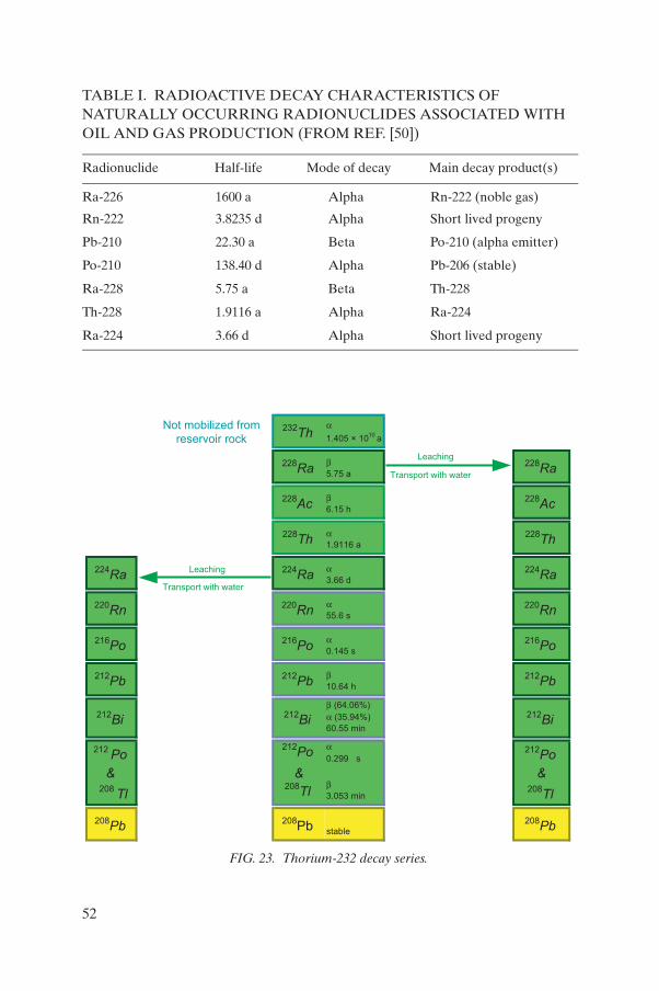
TABLE I. RADIOACTIVE DECAY CHARACTERISTICS OF NATURALLY OCCURRING RADIONUCLIDES ASSOCIATED WITH OIL AND GAS PRODUCTION (FROM REF. [50])
Radionuclide Half-life Mode of decay Main decay product(s)
Ra-226 1600 a Alpha Rn-222 (noble gas)
Rn-222 3.8235 d Alpha Short lived progeny
Pb-210 22.30 a Beta Po-210 (alpha emitter)
Po-210 138.40 d Alpha Pb-206 (stable)
Ra-228 5.75 a Beta Th-228
Th-228 1.9116 a Alpha Ra-224
Ra-224 3.66 d Alpha Short lived progeny
232Th
a1.405 × 10
10a
228Ra
b5.75 a
228Ra
228Ac
b6.15 h
228Ac
228Th
a1.9116 a
228Th
224Ra
224Ra
a3.66 d
224Ra
220Rn
220Rn
a55.6 s
220Rn
216Po
216Po
a0.145 s
216Po
212Pb
212Pb
b10.64 h
212Pb
212Bi
212Bi
b (64.06%)
a (35.94%)
60.55 min
212Bi
212Po
212Po
a0.299 µs
212Po
& &
208Tl
208Tl
b3.053 min
208Tl
208Pb
208Pb stable
208Pb
Leaching
Leaching
Transport with water
Transport with water
Not mobilized from
reservoir rock
&
FIG. 23. Thorium-232 decay series.
52
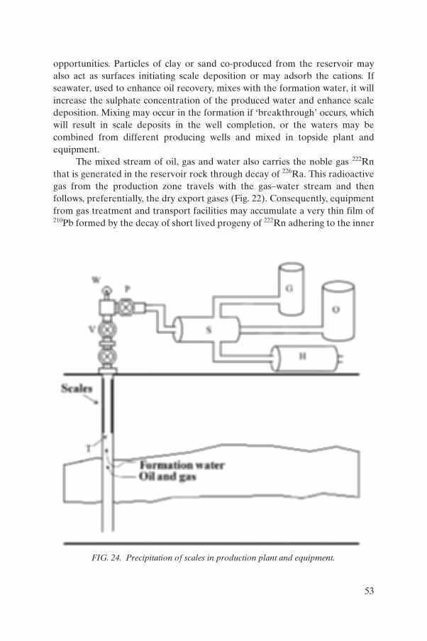
opportunities. Particles of clay or sand co-produced from the reservoir mayalso act as surfaces initiating scale deposition or may adsorb the cations. Ifseawater, used to enhance oil recovery, mixes with the formation water, it willincrease the sulphate concentration of the produced water and enhance scaledeposition. Mixing may occur in the formation if ‘breakthrough’ occurs, whichwill result in scale deposits in the well completion, or the waters may becombined from different producing wells and mixed in topside plant andequipment.
The mixed stream of oil, gas and water also carries the noble gas 222Rnthat is generated in the reservoir rock through decay of 226Ra. This radioactivegas from the production zone travels with the gas–water stream and thenfollows, preferentially, the dry export gases (Fig. 22). Consequently, equipmentfrom gas treatment and transport facilities may accumulate a very thin film of210Pb formed by the decay of short lived progeny of 222Rn adhering to the inner
FIG. 24. Precipitation of scales in production plant and equipment.
53

surfaces of gas lines. These 210Pb deposits are also encountered in liquefiednatural gas processing plants [33–37].
A quite different mechanism results in the mobilization, from thereservoir rock, of stable lead that contains relatively high concentrations of theradionuclide 210Pb. This mechanism, although not well understood [49], hasbeen observed in a number of gas production fields and results in thedeposition of thin, active lead films on the internal surfaces of productionequipment and the appearance of stable lead and 210Pb in sludge. Condensates,extracted as liquids from natural gas, may contain relatively high levels of 222Rnand unsupported 210Pb. In addition, 210Po is observed at levels in excess of itsgrandparent 210Pb, indicating direct emanation from the reservoir (Fig. 22).
5.3. MAIN FORMS OF APPEARANCE OF NORM
The main forms of appearance of NORM in oil and gas production aresummarized in Table II.
An additional type of NORM associated with oil production has beenreported recently [51]. Biofouling/corrosion deposits occurring within variousparts of seawater injection systems, including injection wells and cross-countrypipelines, have been found to contain significantly enhanced concentrations ofuranium originating from the seawater (where it is present in concentrations ofa few parts per billion) as a result of the action of sulphate-reducing bacteriaunder anaerobic conditions.
Scale deposition interferes in the long term with the production processby blocking transport through the pay zone, flow lines and produced waterlines, and may interfere with the safe operation of the installation. Operatorstry to prevent deposition of scales through the application of chemical scaleinhibitors in the seawater injection system, in the topside equipment locateddownstream from the wellhead, or in the producing well [52]. To the extent thatthese chemicals prevent the deposition of the sulphate and carbonate scales,the radium isotopes will pass through the production system and be releasedwith the produced water. Methods of chemical descaling are applied in situusing scale dissolvers when scaling interferes with production and mechanicalremoval is not the method of choice [53, 54].
The extent of mobilization of radionuclides from reservoirs and theirappearance in produced water and production equipment varies greatlybetween installations and between individual wells. In general, heavier scalingis encountered more frequently in oil producing installations than in gasproduction facilities. Over the production lifetime, the produced water maybecome increasingly more saline, indicating the co-production of brine. This
54

may enhance the dissolution of the Group II elements — including radium —from the reservoir rock in a manner similar to the effect of seawater injectionwhen it is used to enhance recovery. Therefore, over the lifetime of a well,NORM may be virtually absent at first but then start to appear later. Themobilization of lead with 210Pb is also variable. The extent to which sludge isproduced and the need to remove it regularly from separators and systemshandling produced water also vary strongly between reservoirs, individualwells, installations and production conditions. As a consequence, there areneither typical concentrations of radionuclides in NORM from oil and gasproduction, nor typical amounts of scales and sludge being produced annuallyor over the lifetime of a well.
In the separation of natural gas by liquefaction, radon can becomeconcentrated with gases that have similar liquefaction temperatures. It isexpected that 210Po and 210Pb would also become concentrated in certain partsof the process [36].
TABLE II. NORM IN OIL AND GAS PRODUCTION
Type Radionuclides Characteristics Occurrence
Ra scales Ra-226, Ra-228, Ra-224 and their progeny
Hard deposits of Ca, Sr, Ba sulphates and carbonates
Wet parts of production installationsWell completions
Ra sludge Ra-226, Ra-228, Ra-224 and their progeny
Sand, clay, paraffins, heavy metals
Separators, skimmer tanks
Pb deposits Pb-210 and its progeny
Stable lead deposits Wet parts of gas production installationsWell completions
Pb films Pb-210 and its progeny
Very thin films Oil and gas treatment and transport
Po films Po-210 Very thin films Condensates treatment facilities
Condensates Po-210 Unsupported Gas production
Natural gas Rn-222Pb-210, Po-210
Noble gasPlated on surfaces
Consumers domainGas treatment and transport systems
Produced water
Ra-226, Ra-228, Ra-224 and/or Pb-210
More or less saline, large volumes in oil production
Each production facility
55

5.4. RADIONUCLIDE CONCENTRATIONS IN NORM
A large amount of data has been collected over the years on the radio-nuclide concentrations in NORM, although relatively few reports have beenpublished. It would appear that the concentrations of 226Ra, 228Ra and 224Ra inscales and sludge range from less than 0.1 Bq/g up to 15 000 Bq/g [49](Table III). Generally, the activity concentrations of radium isotopes are lowerin sludge than in scales. The opposite applies to 210Pb, which usually has arelatively low concentration in hard scales but which may reach a concentrationof more than 1000 Bq/g in lead deposits and sludge. Although thorium isotopesare not mobilized from the reservoir, the decay product 228Th starts to grow infrom 228Ra after deposition of the latter. As a result, when scales containing228Ra grow older, the concentration of 228Th increases to about 150% of theconcentration of 228Ra still present.
5.5. RADIATION PROTECTION ASPECTS OF NORM
In the absence of suitable radiation protection measures, NORM in theoil and gas industry could cause external exposure during production owing to
TABLE III. CONCENTRATIONS OF NORM IN OIL, GAS AND BY-PRODUCTS (FROM REF. [49])
Radio-nuclide
Crude oilBq/g
Natural gasBq/m3
Produced waterBq/L
Hard scaleBq/g
SludgeBq/g
U-238 0.000 000 1–0.01 0.0003–0.1 0.001–0.5 0.005–0.01
Ra-226 0.0001–0.04 0.002–1200 0.1–15 000 0.05–800
Po-210 0–0.01 0.002–0.08 0.02–1.5 0.004–160
Pb-210 0.005–0.02 0.05–190 0.02–75 0.1–1300
Rn-222 5–200 000
Th-232 0.000 03–0.002 0.0003–0.001 0.001–0.002 0.002–0.01
Ra-228 0.3–180 0.05–2800 0.5–50
Ra-224 0.5–40
56

accumulations of gamma emitting radionuclides and internal exposures ofworkers and other persons, particularly during maintenance, the transport ofwaste and contaminated equipment, the decontamination of equipment, andthe processing and disposal of waste. Exposures of a similar nature may alsoarise during the decommissioning of oil and gas production facilities and theirassociated waste management facilities.
5.5.1. External exposure
The deposition of contaminated scales and sludge in pipes and vesselsmay produce significant dose rates inside and outside these components(Table IV). Short lived progeny of the radium isotopes, in particular 226Ra, emitgamma radiation capable of penetrating the walls of these components, and thehigh energy photon emitted by 208Tl (one of the progeny of 228Th) cancontribute significantly to the dose rate on outside surfaces when scale hasbeen accumulating over a period of several months. The dose rates depend onthe amount and activity concentrations of the radionuclides present inside andthe shielding provided by pipe or vessel walls. Maximum dose rates are usuallyin the range of up to a few microsieverts per hour. In exceptional cases, doserates measured directly on the outside surfaces of production equipment havereached several hundred microsieverts per hour [49, 55], which is about 1000times greater than normal background values due to cosmic radiation and
TABLE IV. EXTERNAL GAMMA RADIATION DOSE RATES OBSERVED IN SOME OIL PRODUCTION AND PROCESSING FACILITIES
Location Dose rate (µSv/h)
Down hole tubing, safety valves (internal) up to 300
Wellheads, production manifold 0.1–22.5
Production lines 0.3–4
Separator (scale, measured internally) up to 200
Separator (scale, measured externally) up to 15
Water outlets 0.2–0.5
57
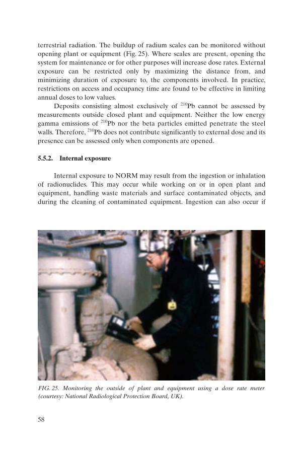
terrestrial radiation. The buildup of radium scales can be monitored withoutopening plant or equipment (Fig. 25). Where scales are present, opening thesystem for maintenance or for other purposes will increase dose rates. Externalexposure can be restricted only by maximizing the distance from, andminimizing duration of exposure to, the components involved. In practice,restrictions on access and occupancy time are found to be effective in limitingannual doses to low values.
Deposits consisting almost exclusively of 210Pb cannot be assessed bymeasurements outside closed plant and equipment. Neither the low energygamma emissions of 210Pb nor the beta particles emitted penetrate the steelwalls. Therefore, 210Pb does not contribute significantly to external dose and itspresence can be assessed only when components are opened.
5.5.2. Internal exposure
Internal exposure to NORM may result from the ingestion or inhalationof radionuclides. This may occur while working on or in open plant andequipment, handling waste materials and surface contaminated objects, andduring the cleaning of contaminated equipment. Ingestion can also occur if
FIG. 25. Monitoring the outside of plant and equipment using a dose rate meter(courtesy: National Radiological Protection Board, UK).
58

precautions are not taken prior to eating, drinking, smoking, etc. More detailon this issue is provided in Section 5.5.4.2.
Effective precautions are needed during the aforementioned operationsto contain the radioactive contamination and prevent its transfer to areaswhere other persons might also be exposed. The non-radioactive characteristicsof scales and sludge also demand conventional safety measures, and thereforethe risk of ingesting NORM is likely to be very low indeed. However, cleaningcontaminated surfaces during repair, replacement, refurbishment or otherwork may generate airborne radioactive material, particularly if dry abrasivetechniques are used. The exposure from inhalation could become significantif effective personal protective equipment (including respiratory protection)and/or engineered controls are not used.
The potential committed dose from inhalation depends on both thephysical and chemical characteristics of NORM. It is important to consider theradionuclide composition and activity concentrations, the activity aerodynamicsize distribution of the particles (quantified by the activity median aerodynamicdiameter, or AMAD), and the chemical forms of the elements and the corre-sponding lung absorption types. Table II-V (Schedule II) of the BSS [2] quotesthe following lung absorption types for the elements of interest for dose calcu-lations:
(a) Radium (all compounds): medium (M)(b) Lead (all compounds): fast (F)(c) Polonium (all unspecified compounds): fast (F)
(oxides, hydroxides, nitrates): medium (M)(d) Bismuth (nitrate): fast (F)
(all unspecified compounds): medium (M)(e) Thorium (all unspecified compounds): medium (M)
(oxides, hydroxides): slow (S).
Table V gives the effective dose per unit intake of dust particles of 5 µmAMAD (the default size distribution for normal work situations) and 1 µmAMAD (a size distribution that may be more appropriate for work situationssuch as those involving the use of high temperature cutting torches). For eachcase, values are quoted for the slowest lung absorption type listed in the BSS (Sfor thorium, M for radium, polonium and bismuth, and F for lead — as notedabove). In addition, values for 5 µm AMAD calculated by Silk [56] are quoted,based on a more conservative assumption that all radionuclides are of lungabsorption type S.
Table V indicates that the inhalation of particles of 5 µm AMAD incorpo-rating 226Ra (with its complete decay chain in equilibrium), 228Ra, and 224Ra
59

(with its complete decay chain in equilibrium), each at a concentration of10 Bq/g, would deliver a committed effective dose per unit intake of about0.1–1 mSv/g, the exact value depending on the extent of ingrowth of 228Th from228Ra and the lung absorption types assumed. For 1 µm AMAD particles, thecommitted effective dose per unit intake would be about 25–30% higher (basedon the slowest lung absorption types listed in the BSS).
5.5.3. Decontamination of plant and equipment
The removal of NORM-containing scales and sludges from plant andequipment, whether for production and safety reasons or during decommis-sioning, needs to be carried out with adequate radiation protection measureshaving been taken and with due regard for other relevant safety, wastemanagement and environmental aspects. In addition to the obvious industrialand fire hazards, the presence of other contaminants such as hydrogensulphide, mercury and hydrocarbons (including benzene) may necessitate theintroduction of supplementary safety measures.
On-site decontamination is the method preferred by operators when theaccumulation of scales and sludges interferes with the rate and safety of oil andgas production, especially when the components cannot be reasonablyremoved and replaced or when they need no other treatment before continueduse. The work may be carried out by the operator’s workers but is usuallycontracted out to service companies. It will necessitate arrangements, such asthe construction of temporary habitats, being made to contain any spillage ofhazardous material and to prevent the spread of contamination from the area
TABLE V. DOSE PER UNIT INTAKE FOR INHALATION OF RADIONUCLIDES IN PARTICLES OF NORM SCALE
Radionuclide
Committed effective dose per unit intake (Sv/Bq)
5 µm AMAD 1 µm AMAD
Slowest lung absorption type listed in BSS [2]
Slow (S) absorption type [56]
Slowest lung absorption type listed in BSS [2]
Ra-226 2.2 × 10⁻⁶ 3.8 × 10⁻⁵ 3.2 × 10⁻⁶
Pb-210 1.1 × 10⁻⁶ 4.5 × 10⁻⁶ 8.9 × 10⁻⁷
Po-210 2.2 × 10⁻⁶ 2.8 × 10⁻⁶ 3.0 × 10⁻⁶
Ra-228 1.7 × 10⁻⁶ 1.2 × 10⁻⁵ 2.6 × 10⁻⁶
Th-228 3.2 × 10⁻⁵ 3.2 × 10⁻⁵ 3.9 × 10⁻⁵
Ra-224 2.4 × 10⁻⁶ 2.8 × 10⁻⁶ 2.9 × 10⁻⁶
60

designated for the decontamination work. Decontamination work has to beperformed off the site where:
(a) On-site decontamination cannot be performed effectively and/or in aradiologically safe manner;
(b) The plant or equipment has to be refurbished by specialists prior toreinstallation;
(c) The plant or equipment needs to be decontaminated to allow clearancefrom regulatory control for purposes of reuse, recycling or disposal asnormal waste.
Service companies hired to perform decontamination work need to bemade fully aware of the potential hazards and the rationale behind thenecessary precautions, and may need to be supervised by a qualified person.The service companies may be able to provide specific facilities and equipmentfor the safe conduct of the decontamination operations, for example aconverted freight container on the site (Fig. 26) or a designated area dedicatedto the task (Fig. 27). Personal protective measures will comprise protective
FIG. 26. Workers wearing personal protective equipment decontaminating a valve insidean on-site facility (courtesy: National Radiological Protection Board, UK).
61
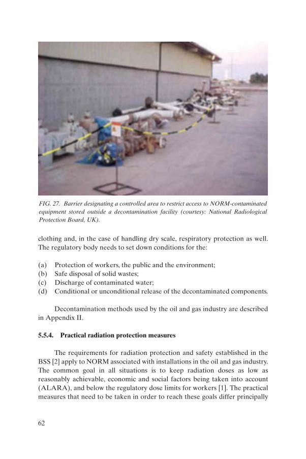
clothing and, in the case of handling dry scale, respiratory protection as well.The regulatory body needs to set down conditions for the:
(a) Protection of workers, the public and the environment;(b) Safe disposal of solid wastes;(c) Discharge of contaminated water; (d) Conditional or unconditional release of the decontaminated components.
Decontamination methods used by the oil and gas industry are describedin Appendix II.
5.5.4. Practical radiation protection measures
The requirements for radiation protection and safety established in theBSS [2] apply to NORM associated with installations in the oil and gas industry.The common goal in all situations is to keep radiation doses as low asreasonably achievable, economic and social factors being taken into account(ALARA), and below the regulatory dose limits for workers [1]. The practicalmeasures that need to be taken in order to reach these goals differ principally
FIG. 27. Barrier designating a controlled area to restrict access to NORM-contaminatedequipment stored outside a decontamination facility (courtesy: National RadiologicalProtection Board, UK).
62
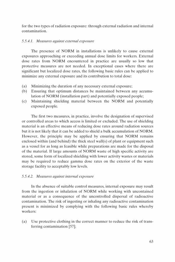
for the two types of radiation exposure: through external radiation and internalcontamination.
5.5.4.1. Measures against external exposure
The presence of NORM in installations is unlikely to cause externalexposures approaching or exceeding annual dose limits for workers. Externaldose rates from NORM encountered in practice are usually so low thatprotective measures are not needed. In exceptional cases where there aresignificant but localized dose rates, the following basic rules can be applied tominimize any external exposure and its contribution to total dose:
(a) Minimizing the duration of any necessary external exposure;(b) Ensuring that optimum distances be maintained between any accumu-
lation of NORM (installation part) and potentially exposed people; (c) Maintaining shielding material between the NORM and potentially
exposed people.
The first two measures, in practice, involve the designation of supervisedor controlled areas to which access is limited or excluded. The use of shieldingmaterial is an effective means of reducing dose rates around radiation sourcesbut it is not likely that it can be added to shield a bulk accumulation of NORM.However, the principle may be applied by ensuring that NORM remainsenclosed within (and behind) the thick steel wall(s) of plant or equipment suchas a vessel for as long as feasible while preparations are made for the disposalof the material. If large amounts of NORM waste of high specific activity arestored, some form of localized shielding with lower activity wastes or materialsmay be required to reduce gamma dose rates on the exterior of the wastestorage facility to acceptably low levels.
5.5.4.2. Measures against internal exposure
In the absence of suitable control measures, internal exposure may resultfrom the ingestion or inhalation of NORM while working with uncontainedmaterial or as a consequence of the uncontrolled dispersal of radioactivecontamination. The risk of ingesting or inhaling any radioactive contaminationpresent is minimized by complying with the following basic rules wherebyworkers:
(a) Use protective clothing in the correct manner to reduce the risk of trans-ferring contamination [57];
63
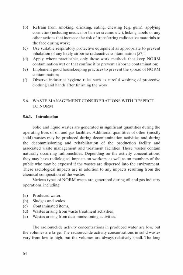
(b) Refrain from smoking, drinking, eating, chewing (e.g. gum), applyingcosmetics (including medical or barrier creams, etc.), licking labels, or anyother actions that increase the risk of transferring radioactive materials tothe face during work;
(c) Use suitable respiratory protective equipment as appropriate to preventinhalation of any likely airborne radioactive contamination [57];
(d) Apply, where practicable, only those work methods that keep NORMcontamination wet or that confine it to prevent airborne contamination;
(e) Implement good housekeeping practices to prevent the spread of NORMcontamination;
(f) Observe industrial hygiene rules such as careful washing of protectiveclothing and hands after finishing the work.
5.6. WASTE MANAGEMENT CONSIDERATIONS WITH RESPECT TO NORM
5.6.1. Introduction
Solid and liquid wastes are generated in significant quantities during theoperating lives of oil and gas facilities. Additional quantities of other (mostlysolid) wastes may be produced during decontamination activities and duringthe decommissioning and rehabilitation of the production facility andassociated waste management and treatment facilities. These wastes containnaturally occurring radionuclides. Depending on the activity concentrations,they may have radiological impacts on workers, as well as on members of thepublic who may be exposed if the wastes are dispersed into the environment.These radiological impacts are in addition to any impacts resulting from thechemical composition of the wastes.
Various types of NORM waste are generated during oil and gas industryoperations, including:
(a) Produced water,(b) Sludges and scales,(c) Contaminated items,(d) Wastes arising from waste treatment activities,(e) Wastes arising from decommissioning activities.
The radionuclide activity concentrations in produced water are low, butthe volumes are large. The radionuclide activity concentrations in solid wastesvary from low to high, but the volumes are always relatively small. The long
64
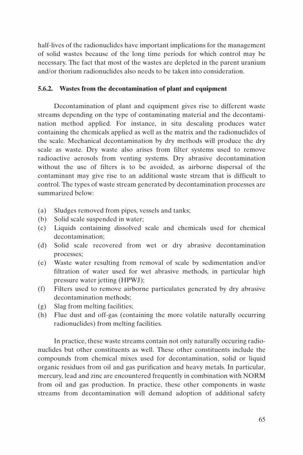
half-lives of the radionuclides have important implications for the managementof solid wastes because of the long time periods for which control may benecessary. The fact that most of the wastes are depleted in the parent uraniumand/or thorium radionuclides also needs to be taken into consideration.
5.6.2. Wastes from the decontamination of plant and equipment
Decontamination of plant and equipment gives rise to different wastestreams depending on the type of contaminating material and the decontami-nation method applied. For instance, in situ descaling produces watercontaining the chemicals applied as well as the matrix and the radionuclides ofthe scale. Mechanical decontamination by dry methods will produce the dryscale as waste. Dry waste also arises from filter systems used to removeradioactive aerosols from venting systems. Dry abrasive decontaminationwithout the use of filters is to be avoided, as airborne dispersal of thecontaminant may give rise to an additional waste stream that is difficult tocontrol. The types of waste stream generated by decontamination processes aresummarized below:
(a) Sludges removed from pipes, vessels and tanks;(b) Solid scale suspended in water;(c) Liquids containing dissolved scale and chemicals used for chemical
decontamination;(d) Solid scale recovered from wet or dry abrasive decontamination
processes;(e) Waste water resulting from removal of scale by sedimentation and/or
filtration of water used for wet abrasive methods, in particular highpressure water jetting (HPWJ);
(f) Filters used to remove airborne particulates generated by dry abrasivedecontamination methods;
(g) Slag from melting facilities;(h) Flue dust and off-gas (containing the more volatile naturally occurring
radionuclides) from melting facilities.
In practice, these waste streams contain not only naturally occuring radio-nuclides but other constituents as well. These other constituents include thecompounds from chemical mixes used for decontamination, solid or liquidorganic residues from oil and gas purification and heavy metals. In particular,mercury, lead and zinc are encountered frequently in combination with NORMfrom oil and gas production. In practice, these other components in wastestreams from decontamination will demand adoption of additional safety
65
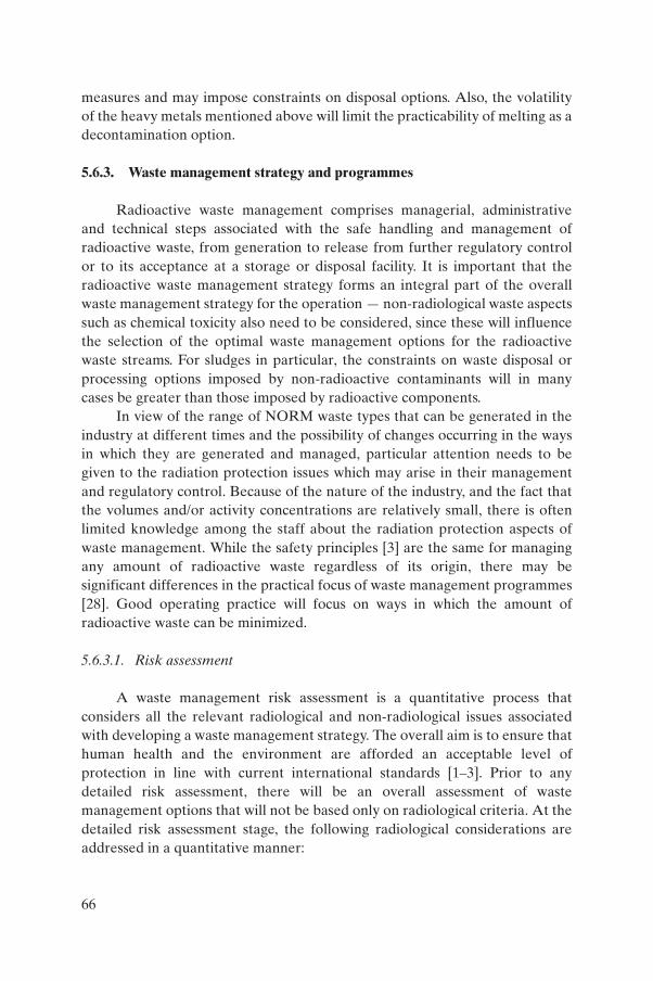
measures and may impose constraints on disposal options. Also, the volatilityof the heavy metals mentioned above will limit the practicability of melting as adecontamination option.
5.6.3. Waste management strategy and programmes
Radioactive waste management comprises managerial, administrativeand technical steps associated with the safe handling and management ofradioactive waste, from generation to release from further regulatory controlor to its acceptance at a storage or disposal facility. It is important that theradioactive waste management strategy forms an integral part of the overallwaste management strategy for the operation — non-radiological waste aspectssuch as chemical toxicity also need to be considered, since these will influencethe selection of the optimal waste management options for the radioactivewaste streams. For sludges in particular, the constraints on waste disposal orprocessing options imposed by non-radioactive contaminants will in manycases be greater than those imposed by radioactive components.
In view of the range of NORM waste types that can be generated in theindustry at different times and the possibility of changes occurring in the waysin which they are generated and managed, particular attention needs to begiven to the radiation protection issues which may arise in their managementand regulatory control. Because of the nature of the industry, and the fact thatthe volumes and/or activity concentrations are relatively small, there is oftenlimited knowledge among the staff about the radiation protection aspects ofwaste management. While the safety principles [3] are the same for managingany amount of radioactive waste regardless of its origin, there may besignificant differences in the practical focus of waste management programmes[28]. Good operating practice will focus on ways in which the amount ofradioactive waste can be minimized.
5.6.3.1. Risk assessment
A waste management risk assessment is a quantitative process thatconsiders all the relevant radiological and non-radiological issues associatedwith developing a waste management strategy. The overall aim is to ensure thathuman health and the environment are afforded an acceptable level ofprotection in line with current international standards [1–3]. Prior to anydetailed risk assessment, there will be an overall assessment of wastemanagement options that will not be based only on radiological criteria. At thedetailed risk assessment stage, the following radiological considerations areaddressed in a quantitative manner:
66

(a) Identification and characterization of radioactive waste source terms;(b) Occupational and public exposures associated with the various waste
management steps from waste generation through to disposal;(c) Long term radiological impact of the disposal method on humans and on
the environment;(d) All phases of the operation from construction to decommissioning;(e) Optimal design of waste management facilities; (f) All significant scenarios and pathways by which workers, the public and
the environment may be subject to radiological (and non-radiological)hazards.
The results of the assessment are then compared with criteria specified bythe regulatory body. These criteria normally include annual dose limits forworkers exposed during operations and for members of the public exposed toradioactive discharges during operation and after closure. The regulatory bodymay specify, in addition, derived levels and limits related to activity concen-tration and surface contamination. These derived values are usually situationspecific and may relate to materials, items or areas that qualify for clearancefrom regulatory control.
5.6.3.2. Regulatory approach
It is important that the regulatory body achieve a consistent regulatoryapproach for protection against the hazards associated with NORM wastes inline with international waste management principles [3] and the BSS [2].Regulatory bodies unfamiliar with control over radioactive wastes in the oiland gas industry need to develop a technical and administrative framework inorder to address appropriately the radiation protection and waste managementissues specific to that industry.
Regulatory frameworks for the control of radioactive wastes generated inthe oil and gas industry are under development in several Member States. Forexample, the management of NORM residues from industrial processes(including the oil and gas industry) by Member States of the European Unionis now subject to the requirements of Article 40 of the Council Directive 96/29/Euratom of 13 May 1996 [58]. Implementation of this is in various states ofprogress and involves the identification of work activities that may give rise tosignificant exposure of workers or of members of the public and, for thoseidentified industries, the development of national radiation protectionregulations in accordance with some or all of the relevant Articles of theDirective.
67
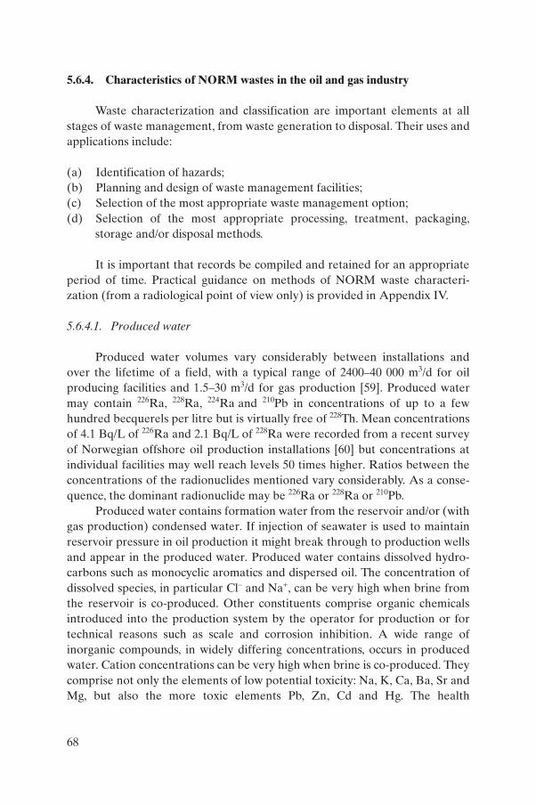
5.6.4. Characteristics of NORM wastes in the oil and gas industry
Waste characterization and classification are important elements at allstages of waste management, from waste generation to disposal. Their uses andapplications include:
(a) Identification of hazards;(b) Planning and design of waste management facilities;(c) Selection of the most appropriate waste management option; (d) Selection of the most appropriate processing, treatment, packaging,
storage and/or disposal methods.
It is important that records be compiled and retained for an appropriateperiod of time. Practical guidance on methods of NORM waste characteri-zation (from a radiological point of view only) is provided in Appendix IV.
5.6.4.1. Produced water
Produced water volumes vary considerably between installations andover the lifetime of a field, with a typical range of 2400–40 000 m3/d for oilproducing facilities and 1.5–30 m3/d for gas production [59]. Produced watermay contain 226Ra, 228Ra, 224Ra and 210Pb in concentrations of up to a fewhundred becquerels per litre but is virtually free of 228Th. Mean concentrationsof 4.1 Bq/L of 226Ra and 2.1 Bq/L of 228Ra were recorded from a recent surveyof Norwegian offshore oil production installations [60] but concentrations atindividual facilities may well reach levels 50 times higher. Ratios between theconcentrations of the radionuclides mentioned vary considerably. As a conse-quence, the dominant radionuclide may be 226Ra or 228Ra or 210Pb.
Produced water contains formation water from the reservoir and/or (withgas production) condensed water. If injection of seawater is used to maintainreservoir pressure in oil production it might break through to production wellsand appear in the produced water. Produced water contains dissolved hydro-carbons such as monocyclic aromatics and dispersed oil. The concentration ofdissolved species, in particular Cl– and Na+, can be very high when brine fromthe reservoir is co-produced. Other constituents comprise organic chemicalsintroduced into the production system by the operator for production or fortechnical reasons such as scale and corrosion inhibition. A wide range ofinorganic compounds, in widely differing concentrations, occurs in producedwater. Cation concentrations can be very high when brine is co-produced. Theycomprise not only the elements of low potential toxicity: Na, K, Ca, Ba, Sr andMg, but also the more toxic elements Pb, Zn, Cd and Hg. The health
68

implications of the last two are the focus of particular attention by regulatorybodies and international conventions.
5.6.4.2. Solid wastes
Solid NORM wastes include sludge, mud, sand and hard porous depositsand scales from the decontamination of tubulars and different types of topsideequipment. The activity concentrations of 226Ra, 228Ra, 224Ra and their decayproducts in deposits and sludge may vary over a wide range, from less than1 Bq/g to more than 1000 Bq/g [34]. For comparison, the average concentrationof radionuclides in the 238U decay series (including 226Ra) in soils is about0.03 Bq/g [61]. A production facility may generate quantities of scales andsludge ranging from less than 1 t/a to more than 10 t/a, depending on its sizeand other characteristics [62, 63]. Decontamination of equipment will producesolid and/or liquid waste, the latter also being contaminated with non-radioactive substances if chemical methods have been used (Section 5.6.2).
The deposition of hard sulphate and carbonate scales in gas productiontubulars, valves, pumps and transport pipes is sometimes accompanied by thetrapping of elemental mercury mobilized from the reservoir rock. Deposits of210Pb have very high concentrations of stable lead mobilized from the reservoirrock. They appear as metallic lead and as sulphides, oxides and hydroxides.
Sludges removed from oil and gas production facilities contain not onlysand, silt and clay from the reservoir but also non-radioactive hazardoussubstances. Therefore, their waste characteristics are not limited to theradioactive constituents. In all sludges in which 210Pb is the dominant radio-nuclide the stable lead concentration is also high. Sludges also contain:
(a) Non-volatile hydrocarbons, including waxes;(b) Polycyclic aromatic hydrocarbons, xylene, toluene and benzene;(c) Varying and sometimes high concentrations of the heavy metals Pb, Zn
and Hg.
In sludges from certain gas fields in Western Europe, mercury concentra-tions of more than 3% (dry weight) are not uncommon.
5.6.5. Disposal methods
Various disposal methods for liquid and solid NORM wastes aredescribed in this section. The use of these methods by the oil and gas industry isnot necessarily an indication that such methods constitute international bestpractice. Regulatory review, inspection, oversight and control over these
69

disposal activities and methods have been generally lacking in the past. Theissue of NORM waste management — and particularly disposal — has beenidentified in recent years as an area of radiation protection and safety thatneeds to be formally addressed by national regulatory bodies wherever oil andgas production facilities are operating.
The process of selecting and developing a disposal method for NORMwastes forms an essential part of the formal radioactive waste managementprogramme for a production facility, although the process is generally notconducted at the level of individual production facilities but at company levelor at the level of associations of companies. In addition, it is important tocommence selection of the optimal waste disposal method at an early stage ofthe project. In developing a waste management strategy the overall aims are to:
(a) Maximize the reduction of risks to humans and to the environmentassociated with a particular disposal method in a cost effective manner;
(b) Comply with occupational and public dose limits and minimize doses inaccordance with the ALARA principle;
(c) Comply with all relevant national and international laws and treaties; (d) Comply with all national regulatory requirements.
Disposal methods for NORM wastes fall into four main categories:
(1) Dilution and dispersal of the waste into the environment, e.g. liquid orgaseous discharges;
(2) Concentration and containment of the waste at authorized waste disposalfacilities;
(3) Processing of the waste with other chemical waste by incineration orother methods;
(4) Disposal of the waste by returning it back to the initial source of thematerial (reinjection into the reservoir).
NORM wastes meeting the clearance criteria [24] specified by theregulatory body may be disposed of as normal (non-radioactive) waste.
5.6.5.1. Regulatory review and approval
The disposal of NORM radioactive wastes originating from the oil andgas industry will require the approval of the regulatory body with regard to:
(a) The acceptability and long term safety of the proposed disposal method;
70

(b) The risk assessments submitted by the owner/operator to demonstratethat the disposal method meets all relevant national and internationallegal and regulatory requirements.
5.6.5.2. Safety implications of waste disposal methods
Disposal methods are discussed in Sections 5.6.5.5 and 5.6.5.6. Whereappropriate, key safety issues and waste management concerns are also listed,since the adoption of a method without the appropriate risk assessment andregulatory approval can lead to significant environmental impacts andassociated remediation costs — particular examples include the disposal ofproduced water in seepage ponds (Section 5.6.5.5(c)) and the shallow landburial of scales and sludges (Section 5.6.5.6(d)). Ultimately, the acceptability ofa particular disposal method for a specific type of NORM waste has to bedecided on the basis of a site specific risk assessment. Since the characteristicsof particular types of NORM waste (i.e. solid or liquid) arising from differentfacilities are not necessarily uniform, it cannot be assumed that the disposalmethods described are suitable for general application, i.e. at any location.
Waste characteristics such as the radionuclides present, their activityconcentrations, and the physical and chemical forms and half-life of thedominant radionuclide can have a major impact on the suitability of aparticular disposal method. Site specific factors such as geology, climate, andgroundwater and surface water characteristics will also influence strongly thelocal suitability of a particular disposal method. Only by considering all therelevant factors in the risk assessment can a considered decision be maderegarding the optimal local disposal option.
5.6.5.3. Significant non-radiological aspects
The selected disposal method, in addition to meeting the fundamentalprinciples of radioactive waste management [3], also has to take account of theenvironmental impact of the significant non-radiological hazards associatedwith the wastes — this applies in particular to sludges that contain hydro-carbons and heavy metals. Discussion of these non-radiological hazards liesoutside the scope of this Safety Report, but they may constitute a dominantaspect in the selection of a disposal method.
5.6.5.4. Storage of solid radioactive wastes
There may be a need to accumulate and store solid NORM wastes (suchas scales) and contaminated objects (such as pipes) prior to taking further steps
71

leading to disposal. The regulatory body has the responsibility for authorizingfacilities for storage of radioactive waste, including storage of contaminatedobjects. A well-designed storage facility will:
(a) Have clear markings to identify its purpose,(b) Contain the waste material adequately,(c) Provide suitable warnings, (d) Restrict access.
The regulatory body will normally require the waste to be encapsulatedor otherwise isolated to an approved standard and the dose rate on the outsideof the storage facility to be kept within values acceptable to the regulatorybody. The regulatory body will probably also impose specific requirements forrecord keeping of the stored waste.
5.6.5.5. Examples of disposal methods for produced water
The large volumes of produced water preclude storage and treatment as apracticable disposal method. The impracticability of treatment applies to bothradioactive and non-radioactive contaminants, although some form oftreatment is usually needed to meet the requirements set by regulatory bodieswith respect to non-radioactive contaminants such as dissolved and dispersedhydrocarbons. Methods that have been used to dispose of produced waterinclude (a) reinjection into the reservoir, (b) discharge into marine waters and(c) discharge into seepage ponds.
(a) Reinjection into the reservoir
Reinjection into the reservoir from which the water originated is acommon practice at many onshore and offshore production facilities, althoughthere are technical constraints such as the potential for breakthrough intoproduction wells. No added radiological risks would seem to be associated withthis disposal method as long as the radioactive material carried by theproduced water is returned in the same or lower concentration to theformations from which it was derived (the confirmation of which might entailtaking some measurements). Should this not be the case, it is important thatany regulatory decision on this method of disposal be supported by anappropriate risk assessment.
72

(b) Discharge into marine waters
Many production installations on the continental shelf discharge theirproduced water into estuaries and the sea. Regulatory requirements withrespect to the discharge of NORM in this way differ between countries; in somecases there are no requirements at all and in others authorizations are requiredif activity concentrations exceed the discharge criteria set by the regulatorybodies. Some discharges may be subject to international maritime conventionssuch as the Convention on the Prevention of Marine Pollution by Dumping ofWastes and Other Matter, 1972 (the London Convention) and the Conventionfor the Protection of the Marine Environment of the North-East Atlantic, 1992(the OSPAR Convention). Various reports that address the fate of radio-nuclides and the radiological risks associated with discharges of NORM-containing produced waters pertain to discharges in coastal and offshore areasof the Gulf of Mexico and are based partly on monitoring results [64–69]. Riskassessments of discharges from platforms on the Dutch continental shelf arebased on modelling of dispersion and exposure pathways [70]. These riskassessments show that the calculated level of risk to humans is stronglydependent on local conditions (estuary, coastal or open sea) and on the degreeof conservatism applied in the dispersion and exposure pathway modelling. It isimportant that risk assessments such as these are carried out and used as thebasis for regulatory requirements with respect to this method of disposal.
(c) Discharge into seepage ponds
At several onshore oil field locations, the produced water is discharged toform artificial lagoons, ponds or seepage pits (Fig. 28). Subsequently, thereleased waters drain to ground leaving radioactive deposits associated withthe soil that eventually require remedial action in accordance with radiationprotection principles [71–73] (Fig. 29). It has been estimated that 30 000contaminated waste pits and bottom sediment sites exist in coastal Louisiana,United States of America [74].
A key factor in determining the acceptability of this method is the radio-logical impact of the contaminated water on local surface water andgroundwater and the potential accumulation of radionuclides in local biota.The degree of impact depends on several factors, including:
(a) The radionuclide activity levels in the produced water,(b) The proportion of the activity contained in the deposited salts,
73
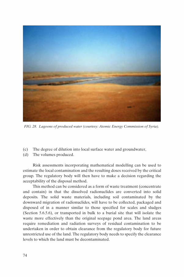
(c) The degree of dilution into local surface water and groundwater, (d) The volumes produced.
Risk assessments incorporating mathematical modelling can be used toestimate the local contamination and the resulting doses received by the criticalgroup. The regulatory body will then have to make a decision regarding theacceptability of the disposal method.
This method can be considered as a form of waste treatment (concentrateand contain) in that the dissolved radionuclides are converted into soliddeposits. The solid waste materials, including soil contaminated by thedownward migration of radionuclides, will have to be collected, packaged anddisposed of in a manner similar to those specified for scales and sludges(Section 5.6.5.6), or transported in bulk to a burial site that will isolate thewaste more effectively than the original seepage pond area. The land areasrequire remediation and radiation surveys of residual contamination to beundertaken in order to obtain clearance from the regulatory body for futureunrestricted use of the land. The regulatory body needs to specify the clearancelevels to which the land must be decontaminated.
FIG. 28. Lagoons of produced water (courtesy: Atomic Energy Commission of Syria).
74

In considering this disposal method, the following aspects need to beaddressed:
(a) Selection of a suitable site;(b) Controls to prevent public access to the area;(c) Risk assessments to determine the human and environmental impacts,
including long term implications, arising from contamination of soil,groundwater and surface water;
(d) Possible need for occupational risk assessments and radiation protectionprogrammes for certain activities or areas, to control exposures and limitthe spread of contamination into public areas;
(e) Quality assurance (QA) and record keeping programmes such as thosefor waste inventories;
(f) Transport costs and compliance with transport regulations [15];(g) Cleanup and remediation costs; (h) Disposal of the solid residues as radioactive wastes.
FIG. 29. Remediation of contaminated land after drying the lagoon (courtesy: AtomicEnergy Commission of Syria).
75
5.6.5.6. Examples of disposal methods for scales and sludges
NORM scales and sludges have a wide range of radionuclide activitylevels and half-lives. These are produced in varying quantities during the life ofan oil or gas facility. Various disposal methods are practised by Member Stateson a routine basis. Other methods have been evaluated by practical applicationand yet others have been assessed on a theoretical basis only. Some disposalmethods are subject to international maritime conventions such as the LondonConvention and the OSPAR Convention. A brief summary with a few selectedreferences is presented below.
(1) Discharge into marine waters
The discharge of solid NORM wastes from offshore platforms is an allowedpractice on the continental shelf of the United Kingdom and Norway [55, 75].Limits are set on residual hydrocarbons and particle diameter. As regards theUK, operators are required to obtain authorization for these discharges and tokeep records. Intentional discharge of solid NORM wastes with produced wateris not allowed on the Dutch continental shelf. This method of disposal can resultin the buildup of localized concentrations of scales around offshore rigs over aperiod of years, and the following aspects need to be addressed:
(a) Need for risk assessments to determine the human and environmentalimpacts;
(b) Possible need for occupational risk assessments and radiation protectionprogrammes for certain activities or areas, to control exposures and limitthe spread of contamination into public areas;
(c) Need for QA and record keeping programmes such as waste inventories.
(2) Injection by hydraulic fracturing
Methods of disposal that employ hydraulic fracturing have beendeveloped and used for offshore generated solid NORM wastes in the Gulf ofMexico [76, 77]. Hydraulic fracturing is also considered in the generic radio-logical dose assessments carried out for various NORM disposal options [78]and for a Class II well1 [79]. In considering this disposal method, the followingaspects need to be addressed:
1 Class II injection wells are a specific category of injection well used by the oiland gas industry to dispose of salt water produced in conjunction with oil or gas, to injectfluids to enhance oil recovery, or to store hydrocarbon liquids.
76
(a) Site selection in relation to the long term stability of the surroundinggeological structures and the required depth of emplacement;
(b) Possible need for encapsulation/stabilization (e.g. in concrete) of the solidwastes;
(c) Need for risk assessments to determine the human and environmentalimpacts;
(d) Possible need for occupational risk assessments and radiation protectionprogrammes for certain activities or areas, to control exposures and limitthe spread of contamination to public areas;
(e) Need for QA and record keeping programmes such as those for wasteinventories.
(3) Disposal in abandoned wells
Disposal in abandoned wells involves the emplacement of NORM solids,whether encapsulated or not, between plugs in the casings of abandoned wells.The method has been the subject of radiological dose assessments [78] and hasbeen described as a preferred option for onshore disposal of scales andmercury-containing sludges [80]. In considering this disposal method, thefollowing aspects need to be addressed:
(a) Site selection with respect to the long term stability of the surroundinggeological structures and the required depth of emplacement — thisshould be viewed in relation to the half-life of the longest lived radio-nuclide 226Ra (1600 years only). It should also be borne in mind that longterm stability of an abandoned and plugged well will be required in anycase to eliminate the risk of a blow-out.
(b) Possible need for encapsulation and the associated costs.(c) Need for risk assessments to determine the human and environmental
impacts, including long term implications, arising from groundwatercontamination.
(d) Possible need for occupational risk assessments and radiation protectionprogrammes for certain activities or areas, to control exposures and limitthe spread of contamination into public areas.
(e) Need for QA and record keeping programmes such as those for wasteinventories.
Proof of long term performance of the isolation of the waste is likely to bemore difficult to provide in the case of non-radioactive constituents (which donot disappear by decay) than in the case of radioactive constituents.
77
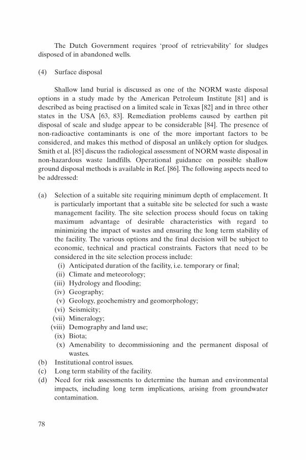
The Dutch Government requires ‘proof of retrievability’ for sludgesdisposed of in abandoned wells.
(4) Surface disposal
Shallow land burial is discussed as one of the NORM waste disposaloptions in a study made by the American Petroleum Institute [81] and isdescribed as being practised on a limited scale in Texas [82] and in three otherstates in the USA [63, 83]. Remediation problems caused by earthen pitdisposal of scale and sludge appear to be considerable [84]. The presence ofnon-radioactive contaminants is one of the more important factors to beconsidered, and makes this method of disposal an unlikely option for sludges.Smith et al. [85] discuss the radiological assessment of NORM waste disposal innon-hazardous waste landfills. Operational guidance on possible shallowground disposal methods is available in Ref. [86]. The following aspects need tobe addressed:
(a) Selection of a suitable site requiring minimum depth of emplacement. Itis particularly important that a suitable site be selected for such a wastemanagement facility. The site selection process should focus on takingmaximum advantage of desirable characteristics with regard tominimizing the impact of wastes and ensuring the long term stability ofthe facility. The various options and the final decision will be subject toeconomic, technical and practical constraints. Factors that need to beconsidered in the site selection process include:
(i) Anticipated duration of the facility, i.e. temporary or final;(ii) Climate and meteorology;
(iii) Hydrology and flooding;(iv) Geography;(v) Geology, geochemistry and geomorphology;
(vi) Seismicity;(vii) Mineralogy;
(viii) Demography and land use;(ix) Biota; (x) Amenability to decommissioning and the permanent disposal of
wastes.(b) Institutional control issues.(c) Long term stability of the facility.(d) Need for risk assessments to determine the human and environmental
impacts, including long term implications, arising from groundwatercontamination.
78
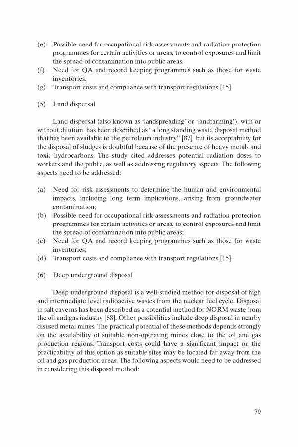
(e) Possible need for occupational risk assessments and radiation protectionprogrammes for certain activities or areas, to control exposures and limitthe spread of contamination into public areas.
(f) Need for QA and record keeping programmes such as those for wasteinventories.
(g) Transport costs and compliance with transport regulations [15].
(5) Land dispersal
Land dispersal (also known as ‘landspreading’ or ‘landfarming’), with orwithout dilution, has been described as “a long standing waste disposal methodthat has been available to the petroleum industry” [87], but its acceptability forthe disposal of sludges is doubtful because of the presence of heavy metals andtoxic hydrocarbons. The study cited addresses potential radiation doses toworkers and the public, as well as addressing regulatory aspects. The followingaspects need to be addressed:
(a) Need for risk assessments to determine the human and environmentalimpacts, including long term implications, arising from groundwatercontamination;
(b) Possible need for occupational risk assessments and radiation protectionprogrammes for certain activities or areas, to control exposures and limitthe spread of contamination into public areas;
(c) Need for QA and record keeping programmes such as those for wasteinventories;
(d) Transport costs and compliance with transport regulations [15].
(6) Deep underground disposal
Deep underground disposal is a well-studied method for disposal of highand intermediate level radioactive wastes from the nuclear fuel cycle. Disposalin salt caverns has been described as a potential method for NORM waste fromthe oil and gas industry [88]. Other possibilities include deep disposal in nearbydisused metal mines. The practical potential of these methods depends stronglyon the availability of suitable non-operating mines close to the oil and gasproduction regions. Transport costs could have a significant impact on thepracticability of this option as suitable sites may be located far away from theoil and gas production areas. The following aspects would need to be addressedin considering this disposal method:
79
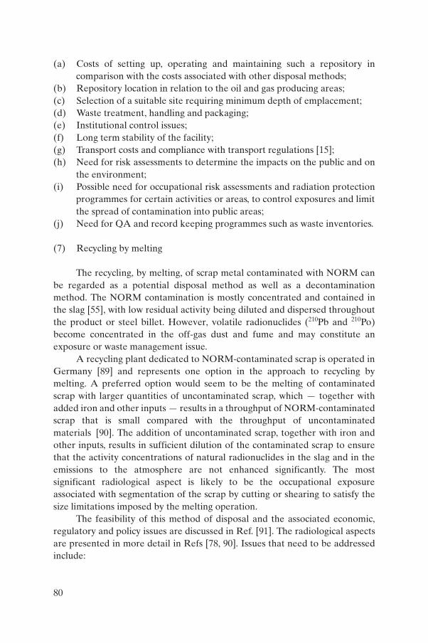
(a) Costs of setting up, operating and maintaining such a repository incomparison with the costs associated with other disposal methods;
(b) Repository location in relation to the oil and gas producing areas;(c) Selection of a suitable site requiring minimum depth of emplacement;(d) Waste treatment, handling and packaging;(e) Institutional control issues;(f) Long term stability of the facility;(g) Transport costs and compliance with transport regulations [15];(h) Need for risk assessments to determine the impacts on the public and on
the environment;(i) Possible need for occupational risk assessments and radiation protection
programmes for certain activities or areas, to control exposures and limitthe spread of contamination into public areas;
(j) Need for QA and record keeping programmes such as waste inventories.
(7) Recycling by melting
The recycling, by melting, of scrap metal contaminated with NORM canbe regarded as a potential disposal method as well as a decontaminationmethod. The NORM contamination is mostly concentrated and contained inthe slag [55], with low residual activity being diluted and dispersed throughoutthe product or steel billet. However, volatile radionuclides (210Pb and 210Po)become concentrated in the off-gas dust and fume and may constitute anexposure or waste management issue.
A recycling plant dedicated to NORM-contaminated scrap is operated inGermany [89] and represents one option in the approach to recycling bymelting. A preferred option would seem to be the melting of contaminatedscrap with larger quantities of uncontaminated scrap, which — together withadded iron and other inputs — results in a throughput of NORM-contaminatedscrap that is small compared with the throughput of uncontaminatedmaterials [90]. The addition of uncontaminated scrap, together with iron andother inputs, results in sufficient dilution of the contaminated scrap to ensurethat the activity concentrations of natural radionuclides in the slag and in theemissions to the atmosphere are not enhanced significantly. The mostsignificant radiological aspect is likely to be the occupational exposureassociated with segmentation of the scrap by cutting or shearing to satisfy thesize limitations imposed by the melting operation.
The feasibility of this method of disposal and the associated economic,regulatory and policy issues are discussed in Ref. [91]. The radiological aspectsare presented in more detail in Refs [78, 90]. Issues that need to be addressedinclude:
80

(a) The possible need for dilution of the contaminated scrap metal withuncontaminated scrap metal to achieve clearance of the steel billets fromregulatory control. This will depend on contamination levels; theregulatory body will have to specify appropriate clearance levels for theradionuclides of concern.
(b) The partitioning behaviour of the main radioactive elements associatedwith different NORM types; Th (from the decay of 228Ra) and Rapartition to the slag, while Po and Pb are emitted with, or recovered from,the off-gas.
(c) The safe disposal of the contaminated slag and other wastes such as fluedust.
(d) Need for risk assessments to determine the human and environmentalimpacts and possible need for radiation protection programmes forcertain activities or areas, and to control exposures and limit the spread ofcontamination into public areas.
(e) Need for QA and record keeping programmes such as those for wasteinventories and activity levels in the slag and product.
The recycling of radioactively contaminated scrap metal has been increas-ingly restricted in recent times because of the potential legal liabilities of metaldealers and scrap merchants [92, 93]. Consequently, almost all large metaldealers and scrap steel smelting operations have installed portal gammaradiation monitors at their premises for the purposes of identifying andrejecting consignments of scrap metals contaminated with radioactivematerials, sealed radiation sources and NORM. Consignments tend to berejected, perhaps unnecessarily, even when it is proven that the portal monitoralarm has been triggered only by NORM.
6. DECOMMISSIONING OF OIL AND GAS PRODUCTION FACILITIES
6.1. INTRODUCTION
When an oil or gas reservoir has been depleted to the extent that furthereconomic exploitation is no longer viable then:
81

(a) The wells will be abandoned and the production and transport systemsdecommissioned and dismantled;
(b) The ancillary offshore and onshore structures (e.g. waste management,storage and treatment facilities) may become redundant and may need tobe dismantled and/or returned to the public domain for unrestricted use;
(c) The owner or operator will request that the regulatory body terminatethe licence for possession, use and processing of radioactive materials.
It is important that the decommissioning aspects of a project beconsidered at an early stage in order to:
(a) Limit the quantities of radioactive waste generated;(b) Limit the areas requiring decontamination;(c) Ensure the selection of adequately safe, cost effective disposal options;(d) Optimize the associated costs;(e) Ensure compliance with the requirements of the regulatory body; (f) Minimize doses to workers and to the public in accordance with the
ALARA principle.
The licensee (i.e. the operator or owner) is responsible for ensuring thatall buildings, land and equipment to be used for unrestricted purposes complywith applicable surface contamination and activity concentration criteriadefined by the regulatory body. The licensee will need to:
(a) Perform an initial survey;(b) Plot the survey points;(c) Indicate any areas of elevated radiation levels; (d) Submit all information to the regulatory body for review, approval and
licence termination.
The decommissioning of oil and gas production facilities and theirassociated structures such as waste management and storage facilities gives riseto a variety of waste materials and items, some of which may be radioactive(e.g. sealed and unsealed sources, NORM scales, contaminated equipment, andconcrete and soil). Given the scale of the oil and gas industry worldwide,decontamination activities (Appendix II) will become increasingly importantand generate significant quantities of wastes over an extended period of time.
82
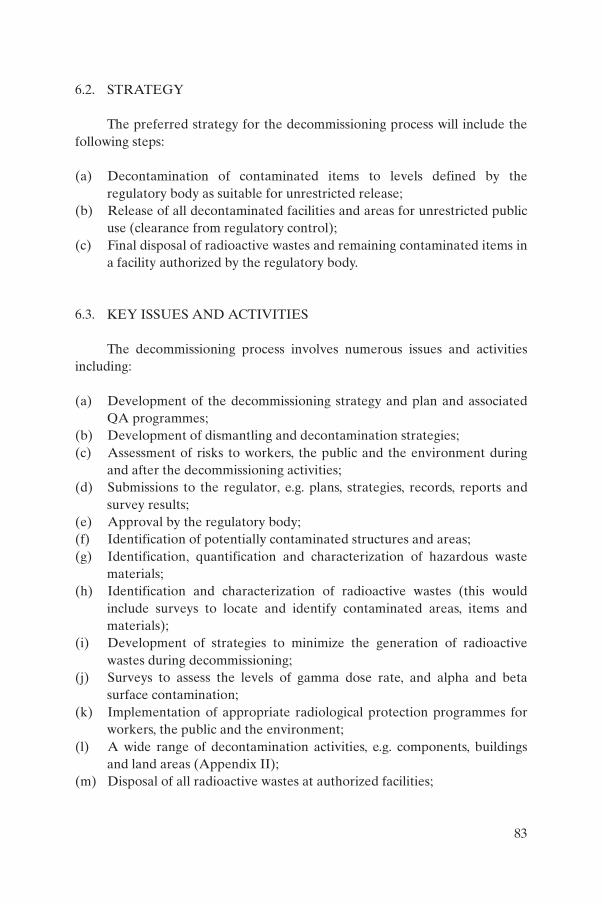
6.2. STRATEGY
The preferred strategy for the decommissioning process will include thefollowing steps:
(a) Decontamination of contaminated items to levels defined by theregulatory body as suitable for unrestricted release;
(b) Release of all decontaminated facilities and areas for unrestricted publicuse (clearance from regulatory control);
(c) Final disposal of radioactive wastes and remaining contaminated items ina facility authorized by the regulatory body.
6.3. KEY ISSUES AND ACTIVITIES
The decommissioning process involves numerous issues and activitiesincluding:
(a) Development of the decommissioning strategy and plan and associatedQA programmes;
(b) Development of dismantling and decontamination strategies;(c) Assessment of risks to workers, the public and the environment during
and after the decommissioning activities;(d) Submissions to the regulator, e.g. plans, strategies, records, reports and
survey results;(e) Approval by the regulatory body;(f) Identification of potentially contaminated structures and areas;(g) Identification, quantification and characterization of hazardous waste
materials;(h) Identification and characterization of radioactive wastes (this would
include surveys to locate and identify contaminated areas, items andmaterials);
(i) Development of strategies to minimize the generation of radioactivewastes during decommissioning;
(j) Surveys to assess the levels of gamma dose rate, and alpha and betasurface contamination;
(k) Implementation of appropriate radiological protection programmes forworkers, the public and the environment;
(l) A wide range of decontamination activities, e.g. components, buildingsand land areas (Appendix II);
(m) Disposal of all radioactive wastes at authorized facilities;
83
(n) Land remediation activities;(o) Transport of radioactive materials in accordance with applicable
regulations [15]; (p) A final radiation survey after dismantling, removal and remediation
activities have been completed.
General guidance on the principles, planning, approach and key issuesinvolved in the decommissioning of industrial facilities and sources is given inthe Safety Guide on Decommissioning of Medical, Industrial and ResearchFacilities [94].
7. ORGANIZATIONAL RESPONSIBILITIES AND TRAINING IN THE OIL AND GAS INDUSTRY
7.1. INTRODUCTION
Radiation protection and the safe management of radioactive waste inthe oil and gas industry rely on the people and organizations involved fulfillingcertain responsibilities. These organizations are:
(a) The various regulatory bodies;(b) The operating organizations (operators) responsible for the oil and gas
fields and the distribution of the products; (c) The service companies (or organizations) that work under contract for
the operator, including but not limited to companies that carry outradiography, work involving gauges, well logging, tracer and workoverservices, fishing operations and NORM decontamination operations.
It is also important for all workers directly involved in work with ionizingradiation, especially those with primary qualifications in other disciplines suchas diving, to be adequately trained and competent for any necessaryinvolvement. Information must be provided to those who are not involved butwho may indirectly be affected by the work and who need information orspecific instructions to minimize their potential exposure. The level ofinstruction needs to be appropriate for the different levels of competence andrecipients will include qualified experts, radiation protection officers (RPOs),qualified workers occupationally exposed to radiation, general workers and
84

other persons. Suggestions for training are given in Appendix III and discussedin detail in Refs [95, 96]. It is important that suitably qualified professionals —those whose credentials have been approved by the regulatory body asrequired — provide the training of all persons concerned. Trainers must befamiliar with the particular technologies, specific procedures and workingenvironments in the oil and gas industry.
7.2. REGULATORY BODIES
National arrangements may specify a number of organizations that haveregulatory authority over different aspects of the oil and gas industry. Theymay, for example, include organizations that regulate:
(a) Development and production of oil and gas;(b) Transport of radioactive and other hazardous material; (c) Possession, use and disposal of radioactive material.
These various regulatory bodies must co-ordinate any overlappingresponsibilities. In these circumstances it is important to identify a leadregulatory body which will assume responsibility for radioactive material andwhich will promulgate appropriate rules and regulations and ensure theirenforcement. Additionally, it will have to develop a method for authorizingpersons and organizations that need to own, use, store, transport, or dispose ofradioactive material. It is desirable that the regulatory body or its nominatedagents be able to perform periodic on-site inspections to ensure compliancewith the applicable rules and regulations. The inspection will include a reviewof required documentation and a physical inspection of the facilities todetermine whether approved safe practices are in use. Checks will be made toconfirm that adequate training is provided and that it is in accordance withprogrammes approved by the regulatory body as required. It is important thatany findings resulting from an inspection be communicated to the persons ororganizations involved and that follow-up inspections be performed to verifythat corrective actions have been implemented [97, 98].
The regulatory body needs to establish criteria to ensure that it receivesnotification from the licensee of any accidents or incidents involvingradioactive material. The types of incident reported include spills, leaks or anyother loss of control of radioactive material, excessive exposures to radiationworkers or members of the public, and lost radioactive material. Reports ofloss include all relevant information such as the make and identificationnumbers of equipment and details of the radioactive material involved,
85

i.e. nuclide, activity and serial number, where applicable. The regulatory bodyarranges that the licensee’s reports include a description of the incident, inves-tigations of exposures of individuals, and actions taken to prevent a recurrenceof that type of incident.
The regulatory body needs to develop a system to document and trackincidents and accidents that occur during the use of radioactive material and ameans of disseminating the ‘lessons learned’ to other similar bodies and to theindustry. This is essential for a regulatory programme to be able to identifytrends and take corrective actions to prevent similar future accidents and/orincidents.
7.3. THE OPERATING ORGANIZATION (OPERATOR)
For the purposes of this Section, the operating organization is the organi-zation responsible for the production and distribution of the oil and gasextracted by the facility (or facilities) under its authority. This organization mayor may not be licensed to own, possess, or use radioactive material includingNORM. The operator establishes sufficient methods, for example employing aqualified expert in the use of risk assessment techniques, for determiningwhether the operations involve work with ionizing radiation and thereforerequire a licence and/or safe systems of work for the operations. The operatorestablishes procedures to ensure the safe and controlled handling ofradioactive material brought onto the premises by other licensees. If theactivities involving ionizing radiation fall under the direct responsibility of theoperator, then the operator has to apply for an authorization, as required bythe regulatory body. The operator further needs to appoint an RPO who istechnically competent and knowledgeable in radiation protection matters. TheRPO will take the lead in developing and implementing a radiation protectionplan. The duties of the RPO may include:
(a) Monitoring radiation and contamination;(b) Identifying and maintaining an inventory of accumulations of NORM;(c) Maintaining an inventory of any other sources of radiation possessed by
the operator;(d) Approving and overseeing the work of any contractor or service company
using ionizing radiation on the operator’s property;(e) Providing hazard assessments and identifying controlled and supervised
areas;(f) Using a QA programme for maintaining protection measures;
86

(g) Controlling access to controlled areas;(h) Arranging radiological assessments of samples and individual dose
assessments;(i) Drawing up and reviewing written administrative procedures for work in
areas where radioactive material is handled;(j) Checking to ensure compliance with authorized conditions and other
regulatory requirements;(k) Supervising work in areas that are controlled as a result of radiation
levels or storage of radioactive material;(l) Advising and requiring the use of appropriate personal protective
equipment in controlled areas;(m) Providing general advice to, and ensuring the training of, personnel;(n) Investigating and documenting incidents or unusual occurrences;(o) Submitting any reports to the regulatory body, as dictated by national
regulations; (p) Maintaining records and documents in accordance with national regula-
tions.
The operator establishes procedures that ensure the safe handling ofradioactive material including NORM. Moreover, the operator develops safetyprocedures that inform the employees of the type and nature of the radiationand how to protect against unnecessary exposure to radiation. The operatoralso establishes a method for maintaining the inventory and for tracking theaccumulation of NORM and acceptable radioactive waste managementmethods. It is desirable that the safety procedures lay down the responsibilitiesat all levels of the operating organization.
The RPO has the authority to halt any operation if an uncontrolled orunacceptable radiation hazard exists or is perceived to exist. The RPO isresponsible for individual monitoring, workplace monitoring and maintenanceof any necessary protective equipment for the personnel. The RPO isresponsible for ensuring that occupationally exposed employees areadequately trained or instructed as to the radiation hazards, and thatinformation on radiation hazards is communicated to other employees.Suitable training programmes are outlined in Appendix III.
7.4. SERVICE COMPANIES
Service companies perform radiography, drilling, tracer work, workovers,well logging, fishing operations, perforations, NORM decontamination,maintenance and repair, etc. Some of these companies are licensed to possess
87
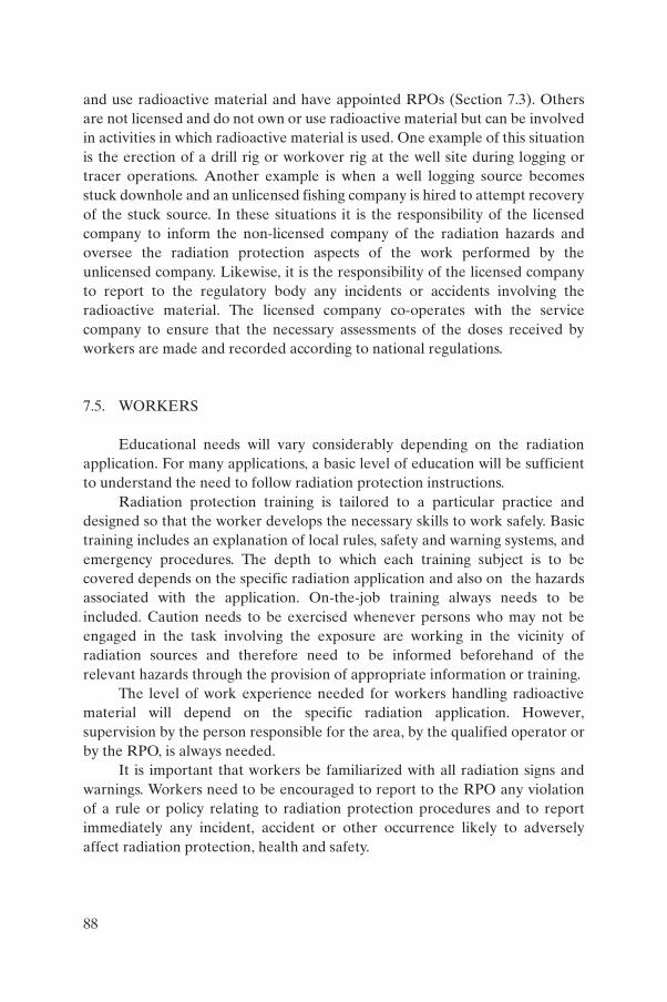
and use radioactive material and have appointed RPOs (Section 7.3). Othersare not licensed and do not own or use radioactive material but can be involvedin activities in which radioactive material is used. One example of this situationis the erection of a drill rig or workover rig at the well site during logging ortracer operations. Another example is when a well logging source becomesstuck downhole and an unlicensed fishing company is hired to attempt recoveryof the stuck source. In these situations it is the responsibility of the licensedcompany to inform the non-licensed company of the radiation hazards andoversee the radiation protection aspects of the work performed by theunlicensed company. Likewise, it is the responsibility of the licensed companyto report to the regulatory body any incidents or accidents involving theradioactive material. The licensed company co-operates with the servicecompany to ensure that the necessary assessments of the doses received byworkers are made and recorded according to national regulations.
7.5. WORKERS
Educational needs will vary considerably depending on the radiationapplication. For many applications, a basic level of education will be sufficientto understand the need to follow radiation protection instructions.
Radiation protection training is tailored to a particular practice anddesigned so that the worker develops the necessary skills to work safely. Basictraining includes an explanation of local rules, safety and warning systems, andemergency procedures. The depth to which each training subject is to becovered depends on the specific radiation application and also on the hazardsassociated with the application. On-the-job training always needs to beincluded. Caution needs to be exercised whenever persons who may not beengaged in the task involving the exposure are working in the vicinity ofradiation sources and therefore need to be informed beforehand of therelevant hazards through the provision of appropriate information or training.
The level of work experience needed for workers handling radioactivematerial will depend on the specific radiation application. However,supervision by the person responsible for the area, by the qualified operator orby the RPO, is always needed.
It is important that workers be familiarized with all radiation signs andwarnings. Workers need to be encouraged to report to the RPO any violationof a rule or policy relating to radiation protection procedures and to reportimmediately any incident, accident or other occurrence likely to adverselyaffect radiation protection, health and safety.
88

Appendix I
RADIATION MONITORING IN THE WORKPLACE
I.1. MEASUREMENT PRINCIPLES AND INSTRUMENTS
I.1.1. Principles
A wide range of instruments is available for carrying out workplacemonitoring for ionizing radiation and radioactive contamination [99].Instruments have not been developed specifically for use at oil and gasproduction and processing facilities and no single instrument is capable ofdetecting all types and energies of the radiations used in the industry. It isimportant to select and make available instruments that are appropriate andefficient for the different applications. Intrinsic safety to permit use inflammable atmospheres may be an important requirement for the instrumentsused.
Radiation measuring instruments are usually designed to quantify onlyone of the two types of potential exposure:
(1) External exposure to penetrating radiation emitted by sources outsidethe human body. Such exposures are associated with sealed sources,unsealed sources such as radiotracers (whether contained or not), bulkquantities of NORM, and radiation generators or machines.
(2) Internal exposure associated with radioactive materials that are in a formcapable of being inhaled or ingested or which otherwise enter andinteract with the human body. Unesaled sources used as radiotracers,radioactive material that has leaked from a sealed source, and NORM arepotentially capable of causing internal exposure. Special attention is to bedrawn to the radioactive noble gas radon which may accumulate near theexit points of sludges, water, mud and other drilling fluids.
Dose rate meters are used to measure the potential external exposure,whereas dosimeters are used to indicate the cumulative external exposure.Surface contamination meters indicate the potential internal exposure whenthe radioactive substance is distributed over a surface; airborne contaminationmeters and gas monitors indicate the potential internal exposure when aradioactive substance is distributed within the atmosphere.
89

I.1.2. Dose rate meters
A suitable and efficient dose rate meter that is matched to the specifictask is capable of measuring external exposure directly, indicating readings ofthe equivalent dose rate in microsieverts per hour. Dose rates of this magnitudeare measured for safety purposes in most situations, such as around sourcestores, near installed level gauges or near accumulated NORM. For otherpurposes, such as taking measurements on the external surfaces of a transportpackage, it is necessary to be able to measure up to several thousand micro-sieverts per hour and an instrument capable of measuring in millisieverts perhour is desirable. In some situations, such as when implementing an emergencyplan to recover an unshielded radiography source, a high dose rate rangeinstrument capable of a continued response where there are dose rates of tensof millisieverts per hour is needed. In such hazardous situations it is importantthat the instrument does not exceed the maximum of its range or, worse still,overload and give a zero reading. There are many wide range or multirangeinstruments covering dose rates of up to several millisieverts per hour and,particularly when working in remote locations, these may be supplemented byspecialized high range instruments (indicating in sieverts per hour) assigned tothe emergency kit.
Instruments with sensitive probes capable of measuring low dose rategamma radiation fields such as the background value at sea level (40–60 nSv/h)are useful. They can be used for monitoring mud returns when it is suspectedthat a sealed source might have ruptured downhole or when it is necessary tomonitor over a wide area to find a lost source or equipment that contains agamma source. This type of instrument may also be used to monitor the outsideof equipment to detect the enhanced dose rates that would indicate thepresence of accumulated sludge or scales containing radium. As the shieldingprovided by the scale or sludge mass itself and that of the wall of the equipmentcan be substantial, it is usually not possible to convert reliably the measureddose rates either into areal inner surface contamination or activity per unitmass of scale or sludge. Internal contamination by 210Pb will not be detected bydose rate meters because all low energy gamma radiation, beta particles andalpha particles from this nuclide and its progeny are shielded by the interveningmetal. Sensitive detectors are available that incorporate both a dose ratemeasuring capability and a gamma spectrometry capability. Gammaspectrometry enables the radiations that are responsible for the dose rate to beanalysed in terms of the radiation energies present. This characterizes,unequivocally, the nature of the radioactive substance (identifying it as 137Cs or226Ra, etc.) emitting the gamma radiation.
90

The response of any dose rate meter is dependent on the characteristicsof the detector it employs, in particular on its detection efficiency at the energy(or energies) of the radiation to which it is exposed. An instrument may havegood detection efficiency over a range of radiation energies, reducing to zero(or nearly zero) efficiency at certain radiation energies perhaps at the rangeextremes. If the detection efficiency is poor the instrument will indicate zeroreadings whatever the actual dose rate attributable to those radiations. Forexample, an instrument that provides an accurate indication of dose rates dueto 137Cs gamma radiation (of an energy of 662 keV) may measure lessaccurately the dose rates due to 241Am gamma radiation (of an energy ofapproximately 60 keV). A specific detector may only be able to detectradiation of a certain type or having an energy greater than some thresholdvalue. The neutron sources used in well logging, typically 241Am–Be, emit bothgamma and neutron radiations that cannot be measured using a singleinstrument. Well logging service companies therefore need both gamma andneutron dose rate meters and to sum the separate measurements to fullydetermine external exposure. However, for the routine occasions whenrepetitive measurements are made, the gamma measuring instrument alonewill normally suffice to provide adequate confirmation of the whereabouts ofthe source and the general condition of the shielded container, etc. The gammameasurement can be used with a gamma–neutron ratio to obtain the total doserate under known exposure conditions. Dose rate measurements should beaveraged over a suitable interval, for example one minute or longer, dependingon whether the prevailing dose rate is apparently constant or transient.
I.1.3. Dosimeters
There are many situations in which workers are exposed and where thetransient dose rates change rapidly with time, for example when a loggingsource is being transferred from the shield to the tool, or when a radiographysource is being projected from the exposure container along the projectionsheath. It is not feasible to measure a single dose rate in such circumstances. Inorder to assess these situations and provide advice on optimizing radiationprotection measures (applying the ALARA principle), a specialist in radiationprotection may need to make ‘time averaged’ dose rate measurements. Forthese an ‘integrating dose rate meter’ is used to assess each exposure andaverage the dose over a longer period of time, for example a working day.There are different types of dosimeter [100] for individual monitoring,generally designed to be pinned or clipped to clothing, that register the totaldose accumulated over the period of exposure. Individuals involved in welllogging or other tasks that involve the use of neutron sources need to wear
91

dosimeters that will measure both gamma and neutron radiations so that thetotal cumulative exposure to these radiations can be assessed. Occupationallyexposed workers must wear a suitable dosimeter and where high dose rates arepossible, such as in radiography, a direct reading dosimeter in addition. Directreading dosimeters provide an alarm to indicate a high dose or dose rate in theevent of accidental exposure. The circumstances of the accident wouldnecessitate further investigation and remedial actions [5].
I.1.4. Surface contamination monitors
Surface contamination monitors are usually designed to measure aspecific type of radiation and often have optimum detection efficiency over alimited range of radiation energies. For example, the detector may respondonly to alpha particles or gamma radiation or to beta and gamma radiations. Itmay perform better in detecting high energy beta particles rather than those oflow energy, or it may be designed to detect low energy gamma radiations butnot those of high energy. It is important to select an instrument that has adetection efficiency optimized for the radiation (or isotope) of interest. Mostsurface contamination monitors indicate in counts/s (or s–1) or counts/min andthe instruments need to be calibrated for the particular radiation beingdetected to enable the indicated reading to be converted into meaningful unitssuch as Bq/cm2. Some instruments are designed either to allow the calibrationresponse factor to be programmed into the instrument, or to allow the isotopebeing used, perhaps as a radiotracer, to be selected from a list on theinstrument so that response is automatically corrected and the readingdisplayed directly in Bq/cm2.
One difficulty in quantifying the contamination due to NORM on asurface is that sludge and scales in which NORM is present contain a mixture ofradioactive substances that are seldom present in the same proportions.Assumptions need to be made about the NORM that is likely to be measuredso that the likely response of the instrument may be determined in a laboratory.This may include examining how the monitor responds to an actual sample ofthe material.
Another difficulty is that the various substances emit radiations thatdiffer widely in their capability to penetrate matter. NORM usually emits alphaparticles but these may be stopped from reaching the detector as a result of thecondition of the surface being investigated. NORM incorporating radiumgenerally emits beta particles and gamma radiation. The beta particles aresignificantly attenuated but even at their reduced energies are likely to bedetected by use of an appropriate instrument. Gamma radiations have a muchgreater range in matter but any instrument used to measure them would always
92

display a significant background gamma radiation component, particularly ifthe surface of interest is close to other accumulations of NORM.
Surface contamination monitors that incorporate either a beta detectoror a combination of separate alpha and beta detectors offer the best options bywhich to monitor thin layers of NORM on surfaces. Care should be taken asmost beta detectors are sensitive to gamma radiation; the presence of ambientgamma radiation that might originate from inside a vessel could in such casesbe misinterpreted as contamination. The use of a beta detector allowsassumptions to be made that are necessary to allow calibration of theinstrument, discriminating against any detectable alpha particles that may bepresent when the NORM contains radium and its progeny. While aninstrument that has a combined response to alpha and beta particles may becalibrated for NORM constituents, interpreting the measurement may beproblematic, depending on the condition of the surface being investigated.
Alpha contamination monitors are intrinsically sensitive to NORMbecause they do not respond to gamma radiation and consequently have nobackground count rate. However, they are vulnerable to mechanical damageand cannot be used reliably to measure surface contamination where thesurface is irregular (e.g. uneven or curved) or covered in a thick layer ofNORM-bearing material (which self-absorbs the radiation) or wet (withdegrees of moisture producing variable self-absorption).
A beta contamination monitor will indicate whether NORM is presentwithin a facility only after access is gained to internal surfaces (Fig. 30). This isbecause the beta particles do not penetrate structural materials such as thesteel walls of tubulars and vessels. If beta contamination is detected outside asystem, then the contaminant must be on the external surface of the objectbeing investigated. It is unlikely that a beta contamination monitor will provideaccurate quantitative measurements of the surface contamination (in terms ofBq/cm2) because assumptions made about the radioactive constituents of thecontaminant may not be entirely correct and significant self-absorption of thebeta radiation occurs in all but thin layers of contamination. At best, betacontamination measurements provide a reliable indication of the need forradiation protection measures and further investigation by sampling and radio-nuclide analysis. Specially designed instruments may be used in specific circum-stances to monitor NORM surface contamination. For example, there areintrinsically safe instruments for use in potentially flammable atmospheres anda cylindrical form of beta detector may be drawn through the inside of wholetubulars to check for internal NORM contamination (Fig. 31).
Gamma radiation detectors (either sensitive dose rate meters or contam-ination meters) may be used to detect accumulations of NORM within plant
93
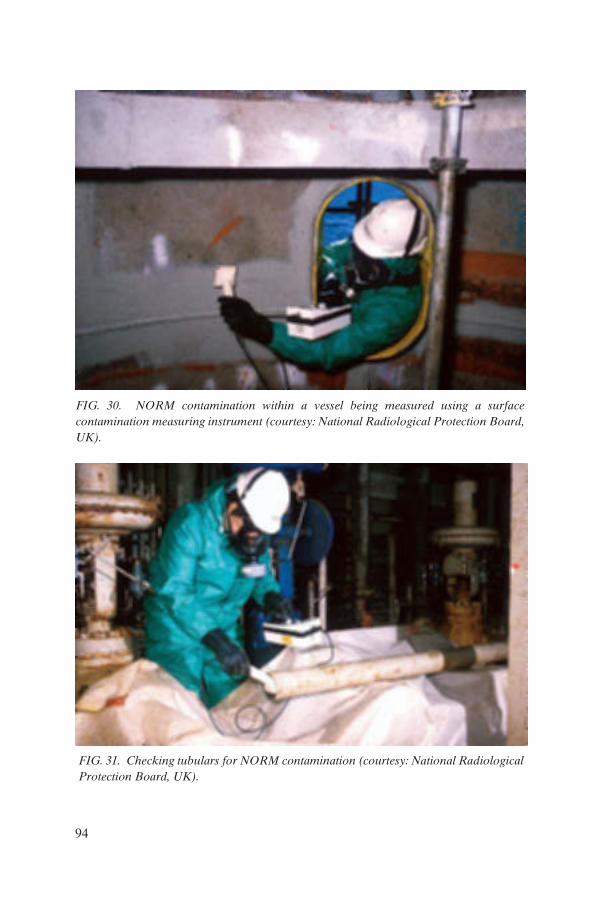
FIG. 30. NORM contamination within a vessel being measured using a surfacecontamination measuring instrument (courtesy: National Radiological Protection Board,UK).
FIG. 31. Checking tubulars for NORM contamination (courtesy: National RadiologicalProtection Board, UK).
94

and equipment and, with appropriate calibration, to measure thick deposits ofNORM surface contamination. Rugged gamma spectrometers may be used inthe field, but it is more likely that samples of the contaminating substances willneed to be submitted to a laboratory for gamma spectrometric analysis toidentify and determine the NORM activity concentrations (in terms of Bq/g).
I.1.5. Contamination monitors for measuring airborne radioactive material
Instruments for measuring airborne contamination are used where thereis a need to assess the risk of radioactive substances either being released intothe atmosphere or resuspended from contaminated surfaces. The instrumentsnormally draw potentially contaminated air at a constant rate through a filter,mainly to monitor airborne alpha emitters, including radon progeny. ‘Activedetectors’ are capable of detecting the accumulated radioactive substance onthe filter and initiating an alarm. Rugged, portable, lightweight personalinstruments exist that measure radon levels and provide an acoustic warningwith short reaction times. Samples of natural gas may be taken and measured ata laboratory to determine the radon content using the Lucas cell method.Personal air samplers based on the use of a filter may also serve as personaldosimeters, but as with many of the installed versions, the filter needs to beassessed elsewhere. These so-called ‘passive detectors’ provide only retro-spective assessments of the working conditions. The filter papers need to behandled carefully to ensure that they are kept flat, undamaged and not contam-inated by contact. These factors, and the need for specialist assessment of thefilters after sampling, limit the usefulness of these instruments in the oil and gasindustry.
I.2. MONITORING STRATEGIES
A sufficient number of suitable and efficient radiation monitoringinstruments need to be provided and used whenever work involves theproduction, processing, handling, use, holding, storage, moving, transport ordisposal of radiation sources or radioactive material. They are to be usedaccording to an overall monitoring strategy. Generally, three levels of expertisemay be recognized: task, routine and special monitoring [1]. Further guidanceon monitoring can be found in Refs [25, 26].
95

I.2.1. Task monitoring
The worker who has day-to-day use of the radiation source or who workswith open sources or NORM performs task monitoring. It is important that theworker (possibly called a qualified operator) be adequately trained to use theinstruments and to interpret the measurements as part of a standard procedure,particularly when operations may involve an increased hazard. For example, aradiation measuring instrument should be used by:
(a) A radiographer to check that a radioactive source has safely returned toits shielded container after an exposure;
(b) The user of a mobile gauge to check that a shutter has closed after thegauge has been used;
(c) A well logging engineer to check the safe return of the sources after alogging tool returns from the well;
(d) A radiotracer technician to check for contamination around highpressure joints and mixer vessels after injection of the radiotracer;
(e) A NORM worker to check for contamination on clothing before leavingan area where decontamination work is being carried out;
(f) A technician to monitor the radon level at the exit points of liquids andgases.
I.2.2. Routine monitoring
In order to oversee, supervise, maintain and keep under review aprogramme for monitoring in the workplace, the RPO will normally carry outroutine monitoring. Surveys are conducted at appropriate regular intervals, butnot necessarily to a predictable timetable. The measurements are intended toconfirm the extent of any designated supervised and controlled areas, to provethe adequacy of measures against external and internal hazards and to revealany deterioration in the standard of radiation protection. A record of themeasurements may be kept for an appropriate period, for example two yearsfrom the date on which the surveys are carried out, which will provide confir-mation of a safe working environment and indicate any trends in the standardof safety provided. Examples of routine monitoring carried out by RPOsinclude the following:
(a) The RPOs of radiography and well logging service companies monitortheir shielded containers and storage conditions.
(b) The RPOs of radiography and well logging service companies monitor toensure the correct placement of barriers demarcating controlled areas.
96

(c) The RPO responsible for installed gauges monitors them to ensure thatthey are adequately shielded and show no signs of physical damage, andto confirm that the shutter of the gauge has closed prior to clearing it forvessel entry.
(d) The RPO of a radiotracer laboratory monitors bench surfaces, wastedisposal routes, storage facilities, etc.
(e) The RPO monitors any transport package for compliance with dose rateand surface contamination limits prior to labelling the package andproviding relevant documentation.
(f) The RPO of an injection company monitors disused packaging prior to itsdisposal by the appropriate route.
(g) The RPO responsible for facilities in which NORM accumulatesmeasures external dose rates where accumulations occur, monitors theplant when it is opened for operational reasons and designates theworkplace prior to authorizing entry of workers. An area monitoringdiagram and an on-site measurements record may be used to facilitatethis (Fig. 32).
(h) The RPO responsible for NORM decontamination confirms the successof measures to contain surface and airborne contamination within thedesignated areas.
(i) The RPO responsible for NORM decontamination monitors todetermine whether an item meets clearance criteria prior to its certifi-cation and release.
FIG. 32. Example of a completed area monitoring diagram.
97

I.2.3. Special monitoring
Special monitoring will normally be carried out by qualified expertscapable of using highly technical instrumentation, interpreting complexmeasurements or applying the results in computational methods in order toreach pertinent conclusions. A report has to be kept detailing the measure-ments, the conclusions and any recommendations that arise from them. Specialmonitoring might also refer to that carried out by a person such as a safetyofficer or inspector employed by the oil and gas operators or the regulatorybodies. The purpose of such monitoring would be to exercise a duty of care forthe overall site or facility, to ensure that safe working practices are followed,and that there is compliance with regulatory requirements and relevant licenceconditions. Special monitoring might be used in:
(a) Situations involving the use of specialized monitoring instruments toassess external exposure and optimize protection against unusualradiation sources with low energy radiations, pulsed or transientemissions, narrow beams, etc.
(b) Critical examinations, hazard evaluations and risk assessments of novelequipment and/or non-routine procedures.
(c) Reviews and measurements to determine shielding requirements and QAassessments of equipment and facilities such as shielded containers,source storage facilities, transport packages, etc.
(d) Audits and inspections of equipment, facilities, procedures and otherarrangements for compliance with predefined company standards andregulatory requirements.
(e) Baseline surveys to assess whether NORM is present in an operatingfacility. Where the survey is negative it may be repeated triennially ormore frequently when changed operating conditions (e.g. changes in thesalinity of produced water) or other factors indicate the need. A flowdiagram for the assessment of closed systems internally contaminatedwith NORM is shown in Fig 33.
(f) Baseline surveys to establish the conditions at a location prior to itsdevelopment as a radioactive waste disposal facility.
(g) Situations where NORM is present in operational plant, sampling andanalysis of produced waters, scales, sludge, natural gas, gas condensates,etc., being carried out, as appropriate, to determine radionuclide andactivity concentrations.
(h) Decommissioning surveys of redundant facilities.
98
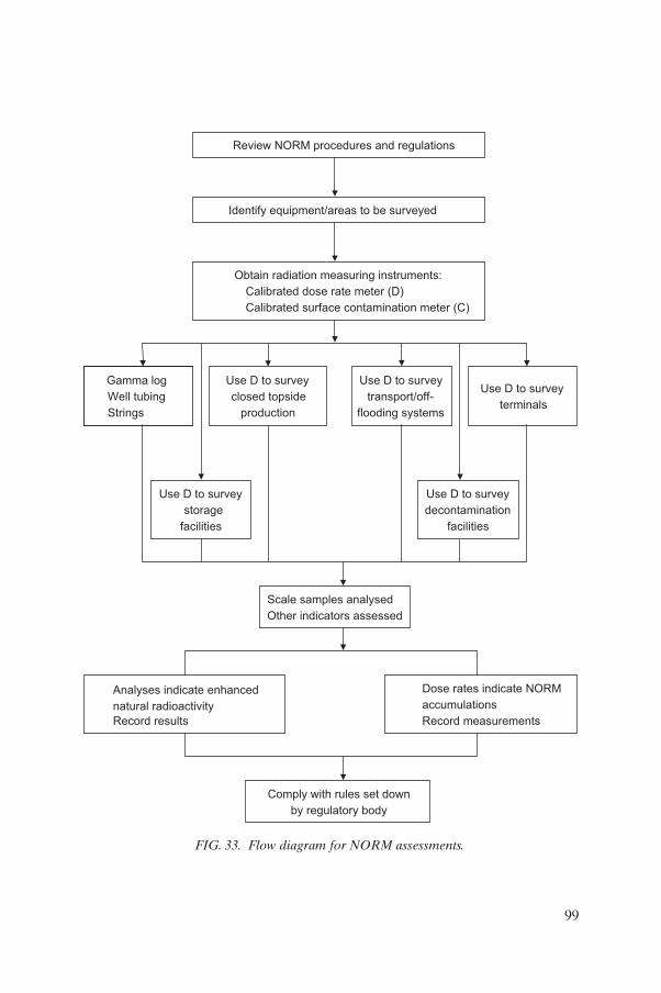
Review NORM procedures and regulations
Identify equipment/areas to be surveyed
Obtain radiation measuring instruments:
Calibrated dose rate meter (D)
Calibrated surface contamination meter (C)
Gamma log
Well tubing
Strings
Use D to survey
closed topside
production
Use D to survey
transport/off-
flooding systems
Use D to survey
terminals
Use D to survey
storage
facilities
Use D to survey
decontamination
facilities
Scale samples analysed
Other indicators assessed
Analyses indicate enhanced
natural radioactivity
Record results
Dose rates indicate NORM
accumulations
Record measurements
Comply with rules set down
by regulatory body
FIG. 33. Flow diagram for NORM assessments.
99

(i) Location and recovery of lost sources, damaged sources, etc., following anincident.
(j) Investigation of accident conditions and provision of specializeddosimetric methods to determine effective doses and acute partial bodydoses.
(k) Obtaining samples and measurements and in the analysis of samples forpresentation as evidence in a legal action.
I.2.4. Other considerations
Some radiation measuring instruments, particularly contaminationmonitoring probes, are not robust and may be more suited to the laboratoryenvironment rather than that of an oil and gas facility. However, there are alsorugged instruments available for on-site contamination measurement anddosimetry, especially for use with gamma emitting radionuclides and radon.Superficial repairs are effected easily in the field provided the necessary spareparts, such as cables and foils to cover the face of the detector, are readilyavailable. The instruments are normally battery powered and a plentiful supplyof batteries is needed, especially where, for example, an instrument may be inalmost constant use during a facility shutdown and the work is in a remotelocation. The battery needs to be tested each time the instrument is switched onand regularly while it is in use. Units operated with rechargeable batteries oraccumulators will demand regular loading cycles and performance testing. It isimportant to have:
(a) A test source of low activity available or at a known location close to ashielded operational sealed source where the instrument may be placedprior to its use to confirm that it continues to provide a familiar response.
(b) Every instrument tested at intervals defined by the regulatory body(usually at least annually) and, where appropriate, calibrated by aqualified expert. The results of such tests are given on a certificate, a copyof which is made available to the user.
Work with a radiation source should not proceed without suitable andefficient radiation measuring instruments being available. It is normally theresponsibility of the service company owning the radiation source to providethe instrument(s). However, the field operator may want to ensure that anadequate range and number of appropriate radiation measuring instrumentsare available or are provided when mobilizing service companies to undertakesuch work.
100

It must be borne in mind that most radiation measuring instruments areelectrical devices operating at high voltage. They may themselves constitute arisk in areas where there are flammable or explosive conditions. Some doserate meters, but very few surface contamination meters, are intrinsically safefor use in these conditions and their use may need to be subject to prior author-ization (a ‘hot work’ permit).
101
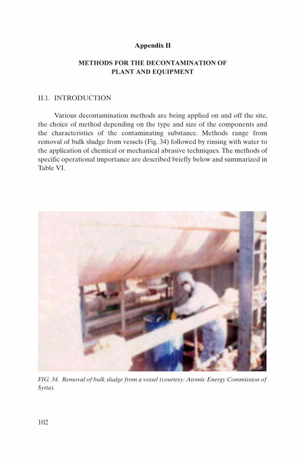
Appendix II
METHODS FOR THE DECONTAMINATION OF
PLANT AND EQUIPMENT
II.1. INTRODUCTION
Various decontamination methods are being applied on and off the site,the choice of method depending on the type and size of the components andthe characteristics of the contaminating substance. Methods range fromremoval of bulk sludge from vessels (Fig. 34) followed by rinsing with water tothe application of chemical or mechanical abrasive techniques. The methods ofspecific operational importance are described briefly below and summarized inTable VI.
FIG. 34. Removal of bulk sludge from a vessel (courtesy: Atomic Energy Commission ofSyria).
102
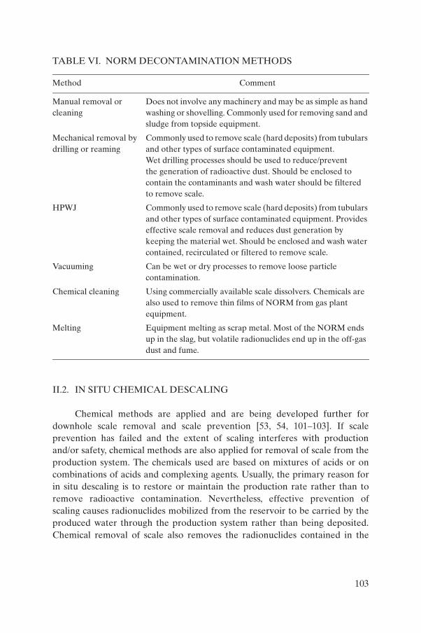
II.2. IN SITU CHEMICAL DESCALING
Chemical methods are applied and are being developed further fordownhole scale removal and scale prevention [53, 54, 101–103]. If scaleprevention has failed and the extent of scaling interferes with production and/or safety, chemical methods are also applied for removal of scale from theproduction system. The chemicals used are based on mixtures of acids or oncombinations of acids and complexing agents. Usually, the primary reason forin situ descaling is to restore or maintain the production rate rather than toremove radioactive contamination. Nevertheless, effective prevention ofscaling causes radionuclides mobilized from the reservoir to be carried by theproduced water through the production system rather than being deposited.Chemical removal of scale also removes the radionuclides contained in the
TABLE VI. NORM DECONTAMINATION METHODS
Method Comment
Manual removal or cleaning
Does not involve any machinery and may be as simple as hand washing or shovelling. Commonly used for removing sand and sludge from topside equipment.
Mechanical removal by drilling or reaming
Commonly used to remove scale (hard deposits) from tubulars and other types of surface contaminated equipment. Wet drilling processes should be used to reduce/prevent the generation of radioactive dust. Should be enclosed to contain the contaminants and wash water should be filtered to remove scale.
HPWJ Commonly used to remove scale (hard deposits) from tubulars and other types of surface contaminated equipment. Provides effective scale removal and reduces dust generation by keeping the material wet. Should be enclosed and wash water contained, recirculated or filtered to remove scale.
Vacuuming Can be wet or dry processes to remove loose particle contamination.
Chemical cleaning Using commercially available scale dissolvers. Chemicals are also used to remove thin films of NORM from gas plant equipment.
Melting Equipment melting as scrap metal. Most of the NORM ends up in the slag, but volatile radionuclides end up in the off-gas dust and fume.
103

deposits, resulting in a liquid stream containing the radionuclides from thedissolved scale.
II.3. ABRASIVE METHODS
Dry and wet abrasive methods employing hand-held devices can beapplied to remove scale from easily accessible surfaces of components. Drygritting, milling, grinding and polishing are normally to be avoided because ofthe risk of spreading radioactive contamination in the air. With wet abrasivemethods, this risk is reduced considerably. Consequently, the application of dryabrasive methods needs protective measures for workers and the environment,which can in practice only be provided by specialized companies or organiza-tions.
HPWJ has been shown to be effective for the decontamination ofcomponents from oil and gas production (Figs 35 and 36). Water pressures of10–250 MPa are used, which necessitate the use of special pumps and safetymeasures. In principle it can be applied on the site and offshore as well asonshore, but its effective and radiologically safe application needs specialexpertise and provisions to obtain the correct impact of the jet, to contain therecoiling mist and to collect and dispose of the water as well as the scale. HPWJis usually applied at a limited number of specialized establishments and servicecompanies that are authorized to operate decontamination facilities [55].Decontamination of tubulars is carried out with the aid of long HPWJ lancesfitted with special nozzles that are moved through the whole length of a tubularwhile the water with the scale is collected at the open ends (Fig. 37). It isrelatively easy to contain the recoiling water from tubulars. The application ofHPWJ to the outer surfaces of components is strongly complicated by the mistproduced by the impact of the jet. In the open air this will cause the spread ofthe radioactive contamination removed from the object and in enclosed spacesit greatly reduces visibility.
II.4. CHEMICAL DECONTAMINATION
Chemical methods have to be applied when the surfaces to be decontam-inated are not accessible for mechanical treatment, when mechanical treatmentwould cause unacceptable damage to the components being refurbished, andwhen the contaminating material is not amenable to mechanical removal.Usually, components have to be degreased by organic or hot alkaline solventsprior to chemical decontamination. The chemicals used are acids, alkalis and
104

complexing agents, which are usually applied in agitated baths. Chemicaldecontamination results in a liquid waste stream containing the dissolving andcomplexing chemicals, and the matrix and radionuclides of the contaminatingmaterial. In many cases, some dissolution of the metal of the component beingdecontaminated cannot be avoided.
FIG. 35. Workers with personal protective equipment and HPWJlance (courtesy: Atomic Energy Commission of Syria).
105

II.5. MELTING
The melting of metallic components contaminated with NORM willseparate the metals from the NORM nuclides. The latter end up in the slag orin the off-gas dust and fume. Decontamination by melting is being applied atdedicated melting facilities, but only on a small scale. The typical processesinvolved in the melting of scrap steel are as follows:
FIG. 36. Workers using HPWJ lance (overhead extractor removesairborne contamination) (courtesy: Atomic Energy Commission ofSyria).
106

(a) Transport to the recycling facility by road, rail or sea, using cranes to loadand offload;
(b) Segmentation, by mechanical or thermal means, into sizes suitable formelting;
(c) Loading by crane or conveyor into an electric arc or induction furnacetogether with iron, fluxes and coke;
(d) Casting of the molten product steel into ingots and mechanized removalof the slag for disposal or reuse;
(e) Recovery and disposal of dust from the off-gas filters.
FIG. 37. Facility for tubular decontamination by HPWJ (courtesy: Atomic EnergyCommission of Syria).
107
Appendix III
TRAINING COURSES FOR PERSONS WORKINGWITH IONIZING RADIATION IN THE OIL AND GAS INDUSTRY
III.1. INTRODUCTION
The main purpose of training is to provide essential knowledge and skillsand to foster the correct attitudes with regard to the safe handling and securityof sealed and unsealed radiation sources. Individuals who are occupationallyexposed to ionizing radiation, or who may be exposed in the course of theirwork, need to receive adequate training in radiation protection. In addition,there are people who, though they may not be occupationally exposed toionizing radiation, need to be trained in radiation protection and safety in orderto perform their duties safely. This Appendix recommends minimum safetytraining requirements for the following persons:
(a) RPOs in the oil and gas industry,(b) Qualified operators,(c) Workers occupationally exposed to radiation.
The aims and objectives of each training course need to be specifiedclearly in advance.
III.2. RPOs
The RPO will need to have had suitable training to supervise effectivelythe work with radiation, ensure compliance with national rules and regulationsand put into effect an appropriate response in the event of an emergency. Abroad level of knowledge in radiation protection is needed, including trainingin emergency preparedness and response, as well as training in specific areas ofwork, e.g. industrial radiography, use of gauges, well logging, radiotracerstudies, decontamination of equipment contaminated with NORM.
As a minimum, the training course needed for an RPO would include thefollowing topics, to be covered by lectures and practical exercises in a period ofnot less than four days:
108
(a) Basic concepts:(i) Types of radiation,
(ii) Interaction of radiation with matter,(iii) Radioactive decay,(iv) Sealed and unsealed sources,(v) Machines (radiation generators).
(b) Radiological units:(i) Activity,
(ii) Absorbed dose,(iii) Equivalent dose,(iv) Dose rate,(v) Commonly used prefixes,
(vi) SI and non-SI units.(c) Dose limitation:
(i) Principles of protection,(ii) BSS and national dose limits,
(iii) Optimization of protection (ALARA).(d) Biological effects of radiation exposure:
(i) Biological systems,(ii) Radiation detriment,
(iii) Stochastic and deterministic effects,(iv) Acute and chronic exposures.
(e) Protection from external exposure:(i) Time, distance and shielding.
(ii) Dose rates associated with sources/machines (output).(iii) Half and tenth value thicknesses.(iv) Practical aspects of the RPO’s work, e.g.:
— radiography equipment,— well logging equipment,— nucleonic gauges,— radiotracer applications,— NORM accumulations.
(v) Safety signs and signals.(f) Protection from internal exposure:
(i) Inhalation, ingestion, absorption of radioactive material;(ii) Values of dose per unit intake;
(iii) Containment of radioactive materials;(iv) Personal protective equipment (clothing and respiratory);(v) Engineered control measures;
(vi) Working procedures and industrial hygiene.
109

(g) Individual (personal) monitoring:(i) Individual dose monitoring.
(ii) Dose record keeping.(iii) Types and characteristics of dosimeters, i.e.:
— film badges,— thermoluminescent dosimeters,— neutron dosimeters,— radon dosimeters,— electronic personal dosimeters (alarms).
(iv) Wearing and care of dosimeters.(h) Radiation measuring instruments and their use:
(i) Types of radiation monitoring survey instrument:— surface contamination monitors,— airborne contamination monitors,— dose rate monitors.
(ii) Laboratory instruments (e.g. spectrometers) and installed monitors.(iii) Correct use and care of monitors.(iv) Testing, calibration and QA.(v) Frequency of monitoring.
(vi) Record keeping.(i) BSS and requirements of the relevant regulatory body:
(i) Hazard evaluations and risk assessments,(ii) Radioactive source accounting and records,
(iii) Storage requirements,(iv) Controlled and supervised areas,(v) Role of the RPO,
(vi) Standard operating procedures,(vii) QA programmes,
(viii) Control of public exposure,(ix) Health surveillance of workers.
(j) Transport and movement of sources:(i) Containment of sources.
(ii) Labelling of packages.(iii) Documentation.(iv) Accountability.(v) Vehicle placards, etc.
(vi) Loading vehicles, vessels, aircraft.(vii) Storage in transit requirements.
110
(k) Radiation accidents and emergency procedures:(i) Examples of accidents and lessons learned,
(ii) Actions to take in the event of an emergency,(iii) Use of emergency equipment,(iv) Contingency plans,(v) Notification(s),
(vi) Written reports of incidents and accidents.
III.3. QUALIFIED WORKERS
A qualified worker has responsibility for the day-to-day use of sealedradiation sources, or works with unsealed sources or NORM. The worker musthave a significant level of expertise in this specific area of work, e.g. industrialradiography, use of gauges, well logging, radiotracer studies, decontaminationof NORM. In addition, in order to exercise responsibility as a qualified worker,the worker will need to have had a minimum standard of training in radiationsafety. The topics to be covered by lectures and practical exercises will be thesame as those defined for the RPO training course, but will be covered in lessdetail. The radiation safety training course for the qualified worker should beprovided over a period of not less than two days.
Radiation protection and safety training needs to be tailored to theparticular application and should be designed so that the worker develops thenecessary skills to work safely. On-the-job training is essential in addition to thetraining course.
III.4. GENERAL WORKERS
The amount of radiation safety information, instruction or trainingneeded for the worker will depend on the extent to which the worker is occupa-tionally exposed to ionizing radiation. At the most basic level, general workerswill all need induction training to ensure that they are capable of recognizingand understanding warning signs, signals and barriers. All workers need tocomply with radiation safety instructions given by qualified workers and RPOs.
Workers who are partially involved with radiation, for exampleindividuals working with gauges (in which the source remains within theprotective housing), industrial radiography assistants and maintenancepersonnel, will need further radiation safety training commensurate with theirinvolvement. The level of training needed will depend on the specific
111
application. However, supervision by the qualified worker or by the RPO isalways necessary.
The radiation safety training provided for workers will be effected bymeans of briefings, demonstrations and practical exercises. This will typicallytake not less than one hour and not more than eight hours.
III.5. MANAGERS AND SAFETY OFFICERS
Managers and safety officers who are not directly involved in work withionizing radiation frequently have a responsibility to co-ordinate or facilitatethe radiation safety objectives of RPOs and qualified workers. The managersand safety officers are involved in the issue of work permits on the work site.Therefore, it is essential that these managers and safety officers are knowl-edgeable as regards radiation safety issues. It is appropriate for managers andsafety officers to receive training equivalent to that of an RPO.
III.6. REFRESHER TRAINING COURSES
Refresher courses are essential for all levels of radiological safetytraining. Such refresher training should be provided at appropriate intervals oras directed by the relevant regulatory body.
112
Appendix IV
METHODS OF RADIOACTIVE WASTE CHARACTERIZATION
IV.1. SCALES AND SLUDGES
The radiological characterization of NORM waste will usually demandnuclide specific analysis by high resolution gamma spectrometry. Only undercertain conditions can reliable estimates of the activity concentration of gammaemitting nuclides be obtained from the known composition and the readings ofdose rate or contamination monitors on the outside of the waste container.Samples of sludges and scales need only drying and homogenizing for thepreparation of counting samples. The method allows the determination ofNORM nuclides as summarized in Table VII.
Because the emanation rate of the 226Ra progeny 222Rn from sludges andscales is usually very low, 226Ra can be measured directly by its 186 keV gammaphoton in all samples with low uranium concentrations. If interference of the186 keV photon from 235U cannot be excluded, 226Ra has to be measured by itsprogeny 214Pb (or 214Bi) and secular equilibrium ascertained either by the lowemanation rate from the sample material or by confinement of the 222Rn in agas-tight geometry.
The assessment of the concentration of 210Pb will need correction for self-absorption of the low energy gamma photon in the sample matrix. Correctionfor self-absorption can be based on transmission measurements with a 210Pbsource. The use of flat cylindrical sample geometries allows such transmissionmeasurements.
Efficiency calibration of the counting system can best be based oncounting, in the same geometry, of reference materials such as IAEA-RGU-1and IAEA-RGTh-1, which can be obtained from the IAEA [104].
Estimation of 210Po activity concentrations will need time consumingspecial analysis involving complete dissolution of the sample matrix, chemicalseparation and alpha spectrometry. In practice, secular equilibrium between210Pb and 210Po in most sludges and scales is assumed in order to obtain anestimate of the concentration of 210Po from the gamma spectrometric analysisof 210Pb. This assumption will not hold, for instance, for the condensatesfraction of natural gas.
Analyses of wastes have to be expressed in a format acceptable to theregulatory body.
113

IV.2. PRODUCED WATER
Methods applicable to the radiological characterization of producedwater depend on the sensitivity needed and on the radionuclides to bedetected. Secular equilibrium between 210Pb and 210Pb cannot necessarily beassumed.
At activity concentrations greater than 10 Bq/L, liquid samplescontaining 226Ra and 228Ra can be counted without preconcentration providedthe counting system is adequately calibrated, and taking the following intoaccount:
(a) Determination of 226Ra on the basis of the count rate of gamma photonsof its progeny 214Pb and 214Bi can introduce large uncertainties caused bycoincidence losses that are not easily quantifiable and by 222Rn escapingfrom the water sample as well as from the sample holder.
(b) The uncertainties caused by coincidence losses in measuring 214Pb and/or214Bi can be avoided if the calibration sources are prepared from thereference material IAEA-RGU-1 or from a certified 226Ra solution (in agas-tight geometry). The calibration factor derived after secularequilibrium has been obtained is insensitive to coincidences.
(c) Because of the large difference between the emission probabilities of the186 keV photon from 226Ra (3.5%) and those of the 352 keV and 609 keVphotons from 214Pb (35%) and 214Bi (45%) respectively, the use of the226Ra photon for determining 226Ra means improving the sensitivity by a
TABLE VII. SUMMARY OF GAMMA SPECTROMETRY ON NORM-CONTAINING SOLIDS FROM THE OIL AND GAS INDUSTRY
Nuclide to be measured
Nuclide to be used from the gamma
spectrumRemarks
Ra-226 Ra-226 (186 keV) If no interference from U-235 is expected.
Ra-226 Pb-214 (352 keV) If interference from U-235 is expected. Use gas-tight geometry if Rn-222 emanates from matrix.
Pb-210 Pb-210 (46.5 keV) Correction needed for self absorption.
Ra-228 Ac-228 (911 keV)
Th-228 Tl-208 (583 keV) Correction needed for decay chain branching.
114

factor of about 10. The sample vessel has to be gas-tight and equilibriumhas to be established before any determination is attempted.
(d) The method is inherently insensitive when used for determining 210Pbbecause of the high self-absorption of its low energy photon (46 keV).
(e) When counting liquid samples of produced water, there is a risk ofundissolved matter settling on the bottom of the sample holder closer tothe detector. This can be avoided by gelling the sample with, for instance,wallpaper glue. Highly saline samples cannot be gelled.
At activity concentrations below 1 Bq/L, the counting efficiency for directmeasurement of 226Ra and 228Ra in produced water will not usually besufficient. Consequently, preconcentration will be needed to reduce uncer-tainties to acceptable levels while maintaining reasonable counting times. Highsensitivities can be obtained using a radium separation technique that involvesthe addition of a barium carrier and the co-precipitation of radium and bariumas insoluble sulphate. The activity of samples of several litres can then beconcentrated in a small amount of solid material that can be counted in a smallvolume sample geometry close to the detector. At the same time, the precipi-tation leaves 40K in the stripped water sample, which reduces the backgroundcount rate of the solids containing the radium isotopes. This procedure alsoenables the determination of 210Pb at levels less than 1 Bq/L if a stable leadcarrier, in addition to the barium carrier, is added to separate 210Pb by precipi-tation of insoluble lead sulphate. Self-absorption correction with a 210Pb sourcecan be carried out as described for scales and sludges, provided a flat cylindricalgeometry is used for counting the precipitate. The use of a small, flat, gas-tightgeometry implies that a thin window N-type high purity germanium detectorwill be used for measurement of the low energy photons of 210Pb emitted by thesample and by the 210Pb source used for self-absorption correction.
115
REFERENCES
[1] INTERNATIONAL ATOMIC ENERGY AGENCY, INTERNATIONALLABOUR OFFICE, Occupational Radiation Protection, Safety Standards SeriesNo. RS-G-1.1, IAEA, Vienna (1999).
[2] FOOD AND AGRICULTURE ORGANIZATION OF THE UNITEDNATIONS, INTERNATIONAL ATOMIC ENERGY AGENCY, INTERNA-TIONAL LABOUR ORGANISATION, OECD NUCLEAR ENERGYAGENCY, PAN AMERICAN HEALTH ORGANIZATION, WORLDHEALTH ORGANIZATION, International Basic Safety Standards for Protec-tion against Ionizing Radiation and for the Safety of Radiation Sources, SafetySeries No. 115, IAEA, Vienna (1996).
[3] INTERNATIONAL ATOMIC ENERGY AGENCY, The Principles of Radioac-tive Waste Management, Safety Series No. 111-F, IAEA, Vienna (1995).
[4] Nuclear Techniques in the Exploration and Exploitation of Energy and MineralResources (Proc. Int. Conf. Vienna, 1990), IAEA, Vienna (1991).
[5] INTERNATIONAL ATOMIC ENERGY AGENCY, Radiation Protection andSafety in Industrial Radiography, Safety Reports Series No. 13, IAEA, Vienna(1999).
[6] INTERNATIONAL ATOMIC ENERGY AGENCY, Manual on Gamma Radi-ography, Practical Radiation Safety Manual No. 1, IAEA, Vienna (1996).
[7] Industrial Application of Radioisotopes and Radiation Technology (Proc. Int.Conf. Grenoble, 1981), IAEA, Vienna (1982).
[8] INTERNATIONAL ORGANIZATION FOR STANDARDIZATION, Radio-nuclide Gauges Designed for Permanent Installation, ISO 7205, Geneva (1986).
[9] INTERNATIONAL ATOMIC ENERGY AGENCY, Manual on NuclearGauges, Practical Radiation Safety Manual No. 3, IAEA, Vienna (1996).
[10] CHARLTON, J.S., et al., Industrial applications of radioisotopes, Phys. Technol. 62 (1975) 67–76.
[11] CHARLTON, J.S., UK Patent Specification 1474395, The UK Patent Office,Newport and London (1977).
[12] CALDWELL, R.L., Nuclear logging methods, Isot. Radiat. Technol. 6 3 (1969)257.
[13] BAKER HUGHES INTEQ, MWD Measurement-while-Drilling, companybrochure no. 602-003, Houston, TX (1993).
[14] INTERNATIONAL ATOMIC ENERGY AGENCY, Handbook on NuclearData for Borehole Logging and Mineral Analysis, Technical Reports Series No.357, IAEA, Vienna (1993).
[15] INTERNATIONAL ATOMIC ENERGY AGENCY, Regulations for the SafeTransport of Radioactive Material, 1996 Edition (Rev.), Safety Standards SeriesNo. TS-R-1 (ST-1, Rev.), IAEA, Vienna (2000).
[16] FUJIMOTO, K., WILSON, J.A., ASHMORE, J.P., Radiation exposure risks tonuclear well logging engineers, Health Phys. 48 (1985) 437– 445.
117

[17] GEIGER, N., MOORE, R.T., Radiological health aspects of oil well logging,Public Health Rep. 81 (1966) 1064–1070.
[18] INTERNATIONAL ORGANIZATION FOR STANDARDIZATION, SealedRadioactive Sources — General Classification, ISO/TC 85/SC 2/WG 11N 31E,Geneva (1990).
[19] INTERNATIONAL ORGANIZATION FOR STANDARDIZATION, SealedRadioactive Sources — Leakage Test Methods, ISO/TC 85/SC 2N 390, Geneva(1988).
[20] INTERNATIONAL ATOMIC ENERGY AGENCY, Lessons Learned fromAccidents in Industrial Radiography, Safety Reports Series No. 7, IAEA, Vienna(1998).
[21] JONES, M.F., GESELL, T.F., NANUS, J., RACSTER, C.E., Radioactive welllogging: A review and an analysis of Texas incidents, Health Phys. 40 (1981) 361–368.
[22] KUMAR, A., MASSAND, O.P., SUBRAHMANIAN, G., Some recent incidentsin radioactive well logging, Bull. Radiat. Prot. 10 4 (1987) 21–24.
[23] INTERNATIONAL ATOMIC ENERGY AGENCY, Generic Procedures forAssessment and Response during a Radiological Emergency, IAEA-TECDOC-1162, Vienna (2000).
[24] INTERNATIONAL ATOMIC ENERGY AGENCY, Clearance Levels for Radi-onuclides in Solid Materials: Application of Exemption Principles, IAEA-TECDOC-855, Vienna (1996).
[25] INTERNATIONAL ATOMIC ENERGY AGENCY, INTERNATIONALLABOUR OFFICE, Assessment of Occupational Exposure Due to ExternalSources of Radiation, Safety Standards Series No. RS-G-1.3, IAEA, Vienna(1999).
[26] INTERNATIONAL ATOMIC ENERGY AGENCY, INTERNATIONALLABOUR OFFICE, Assessment of Occupational Exposure Due to Intakes ofRadionuclides, Safety Standards Series No. RS-G-1.2, IAEA, Vienna (1999).
[27] INTERNATIONAL ATOMIC ENERGY AGENCY, Assessment and Treatmentof External and Internal Radionuclide Contamination, IAEA-TECDOC-869,Vienna (1996).
[28] INTERNATIONAL ATOMIC ENERGY AGENCY, Management of Radioac-tive Waste from the use of Radioactive Materials in Medicine, Industry andResearch, Safety Standards Series, IAEA, Vienna (in preparation).
[29] INTERNATIONAL ATOMIC ENERGY AGENCY, Handling, Conditioningand Storage of Spent Sealed Radioactive Sources, IAEA-TECDOC-1145,Vienna (2000).
[30] INTERNATIONAL ATOMIC ENERGY AGENCY, Guidebook on Radio-isotope Tracers in Industry, Technical Reports Series No. 316, IAEA, Vienna(1990).
118
[31] INTERNATIONAL ORGANIZATION FOR STANDARDIZATION,Measurement of Water Flow in Closed Conduits — Tracer Method — Part 7:Transit Time Method Using Radioactive Tracers, Pub. No. 2975/7, ISO, Geneva(1977).
[32] INTERNATIONAL ORGANIZATION FOR STANDARDIZATION, LiquidFlow Measurement in Open Channels — Dilution Methods for Measurement ofSteady Flow — Part 3: Constant Rate Injection Method and Integration MethodUsing Radioactive Tracers, Pub. No. 555/3, ISO, Geneva (1982).
[33] McLENNAN, J.C., “On the radioactivity of mineral oils and natural gases”, paperpresented at the Int. Electrical Congress, St. Louis, 1904.
[34] KOLB, W.A., WOJCIK, M., Enhanced radioactivity due to natural oil and gasproduction and related radiological problems, The Science of the Total Environ-ment 45 (1985) 77–84.
[35] BORN, H.-J., Verwandte Salze und Erdöl, Kali 30 (1936) 41– 45. [36] GESELL, T.F., Occupational radiation exposure due to 222-Rn in natural gas and
natural gas products, Health Phys. 29 (1975) 681–687.[37] SUMMERLIN, J., PRICHARD, H.M., Radiological health implications of lead-
210 and polonium-210 accumulation in LPG refineries, Am. Ind. Hyg. Assoc. J. 46(1985) 202–205.
[38] KOLB, W.A., WOJCIK, M., Strahlenschutzprobleme bei der Gewinnung undNützung von Erdöl und Erdgas in der Bundesrepublik Deutschland, PTB-BerichtPTB-Ra-17, Physikalisch-Technische Bundesanstalt, Braunschweig und Berlin(1985) (in German).
[39] AMERICAN PETROLEUM INSTITUTE, Bulletin on Management ofNaturally Occurring Radioactive Materials (NORM) in Oil and Gas Production,API Bull. E2, Washington, DC (1992) Section 1.2.
[40] AL-MASRI, M.S., ALI, A.F., KITOU, M., KAWASH, A., Determination ofnaturally occurring radionuclides in scales produced in the oil industry, Rep.AECS-PR/RSS, Atomic Energy Commission of Syria, Damascus (1997).
[41] RAEBURN, G., et al., Low Specific Activity Scale: Origin, Treatment andDisposal, Rep. No. 6.6/127, E&P Forum, London (1988).
[42] OTTO, G.H., A National Survey on Naturally Occurring Radioactive Materials(NORM) in Petroleum Producing and Gas Processing Facilities, AmericanPetroleum Institute, Dallas, TX (1989).
[43] UK OFFSHORE OPERATORS ASSOCIATION LIMITED, Guidelines forOperators on Naturally Occurring Radioactive Substances on Offshore Installa-tions, UKOOA, London and Aberdeen (1985).
[44] WALDRAM, I.M., Natural radioactive scale: The development of safe systems ofwork, J. Petr. Technol. 40 (1988) 1057–1060.
[45] SHELL UK EXPLORATION AND PRODUCTION, Operating Standard OS1.005: Handling of LSA Scale and Contaminated Equipment, Shell UK, London(1990).
119

[46] KEMA, Guidelines for Onshore and Offshore Operators for Handling NaturallyOccurring Radioactive Materials (NORM) and NORM Contaminated Installa-tion Parts, Rep. KEMA 40016-NUC 94 5562 (August 1994), Arnhem (1994) (inDutch).
[47] ATOMIC ENERGY LICENSING BOARD, Guidelines on Radiological Protec-tion for Offshore Oil and Gas Facilities Operators Associated with Technologi-cally Enhanced Naturally Occurring Radioactive Materials, AELB, KualaLumpur (1991).
[48] MILLER, H.T., BRUCE, E.D., COOK, L.M., “The management of occupationaland environmental exposure to naturally occurring radioactive materials(NORM)”, (Proc. 66th Ann. Tech. Conf. Dallas, 1991), Society of PetroleumEngineers, Richardson, TX (1991).
[49] JONKERS, G., HARTOG, F.A., KNAEPEN, A.A.I., LANCEE, P.F.J., “Charac-terization of NORM in the oil and gas production (E&P) industry”, RadiologicalProblems with Natural Radioactivity in the Non-Nuclear Industry (Proc. Int.Symp. Amsterdam, 1997), KEMA, Arnhem (1997).
[50] KINSEY, R.R., et al., “The NUDAT/PCNUDAT program for nuclear data”,Capture Gamma Ray Spectroscopy and Related Topics (Proc. 9th Int. Symp.Budapest, 1996), Springer Verlag, Heidelberg (1997).
[51] BIRD, A.F., ROSSER, H.R., WORRALL, M.E., MOUSLY, K.A.,FAGEEHA, O.I., “Technologically enhanced naturally occurring radioactivematerial associated with sulfate reducing bacteria biofilms in a large seawaterinjection system”, Health, Safety and Environment in Oil and Gas Explorationand Production (Proc. Int. Conf. Kuala Lumpur, 2002), Society of PetroleumEngineers, Richardson, TX (2002).
[52] HEN, J., BRUNGER, A., PETERSON, B.K., YUAN, M.D., RENWICK, J.P.,“A novel scale inhibitor chemistry for downhole squeeze application in high waterproducing sea wells”, Offshore Europe (Proc. Int. Conf. Aberdeen, 1995), Societyof Petroleum Engineers, Richardson, TX (1995).
[53] FORD, W.G.F., GADEKEN, L.L., CALLAHAN, T.J., JACKSON, D., Solventremoves downhole NORM-contaminated BaSO4 scale, Oil Gas J. 94 (1996)65-68.
[54] FIELDER, G.D., “Application and evaluation of scale dissolver treatments”,Corrosion ’94 (Proc. Int. Ann. Conf. Baltimore, 1994), National Association ofCorrosion Engineers, Houston, TX (1994).
[55] VAN WEERS, A.W., et al., Current Practice of Dealing with Natural Radio-activity from Oil and Gas Production in EU Member States, Rep. EU 17621,Office for Official Publications of the European Communities, Luxembourg(1997).
[56] SILK, T.J., KENDALL, G.M., PHIPPS, A.W., Revised estimates of dose fromores and mineral sands, J. Radiol. Prot. 15 (1995) 217–222.
[57] INTERNATIONAL ATOMIC ENERGY AGENCY, Personal Protective Equip-ment, Practical Radiation Technical Manual No. 5, IAEA, Vienna (in prepara-tion).
120

[58] COMMISSION OF THE EUROPEAN COMMUNITIES, Council Directive 96/29/EURATOM/ of 13 May 1996 Laying Down the Basic Safety Standards for theProtection of the Health of Workers and the General Public Against the DangersArising from Ionising Radiation, Off. J. Eur. Comm., Series L, No. 159, Office forOfficial Publications of the European Communities, Luxembourg (1996).
[59] EXPLORATION & PRODUCTION FORUM, North Sea Produced Water: Fateand Effects in the Marine Environment, Rep. No. 2.62/204, E&P Forum, London(1994).
[60] LYSEBO, I., STRAND, T., “NORM in oil production in Norway”, RadiologicalProblems with Natural Radioactivity in the Non-Nuclear Industry (Proc. Int.Symp. Amsterdam, 1997), KEMA, Arnhem (1997).
[61] UNITED NATIONS, Sources and Effects of Ionizing Radiation (2000 Report tothe General Assembly), Vol. 1: Sources, Scientific Committee on the Effects ofAtomic Radiation (UNSCEAR), UN, New York (2000).
[62] AMERICAN PETROLEUM INSTITUTE, Naturally Occurring RadioactiveMaterial (NORM) Disposal Cost Study, Publication 7100, API, Washington, DC(1996).
[63] VEIL, J.A., SMITH, K.P., NORM-disposal options, costs vary, Oil Gas J. 97 1(1999) 37– 43.
[64] MULINO, M.M., RAYLE, M.F., “Produced water radionuclides fate and effects”,Environmental Science Research, Vol. 46 (RAY, J.P., ENGELHART, F.R., Eds),Kluwer Academic, Dordrecht (1993) 281–292.
[65] MEINHOLD, A.F., HAMILTON, L.D., “Radium concentration factors and theiruse in health and environmental risk assessment”, Environmental ScienceResearch, Vol. 46 (RAY, J.P., ENGELHART, F.R., Eds), Kluwer Academic,Dordrecht (1993) 293–302.
[66] MEINHOLD, A.F., HOLTZMAN, S., HAMILTON, L.D., “Health risk assess-ment for radium discharged in produced water”, Government and IndustryWorking Together to find Cost Effective Approaches to Protecting the Environ-ment (Proc. SPE/EPA Conf. Houston, 1995), Society of Petroleum Engineers,Richardson, TX (1995) 357–372.
[67] MEINHOLD, A.F., HOLTZMAN, S., HAMILTON, L.D., DEPHILLIPS, M.P.,Risk Assessment for Produced Water Discharges to Louisiana Open Bays, Rep.BNL-62239, Brookhaven National Laboratory, Upton, NY (1995).
[68] MEINHOLD, A.F., HOLTZMAN, S., Radiation Dose and Risk to RecreationalFisherman from Ingestion of Fish Caught Near Eight Oil Platforms in the Gulf ofMexico, Rep. BNL-65560, Brookhaven National Laboratory, Upton, NY (1998).
[69] HAMILTON, L.D., MEINHOLD, A.F., NAGY, J., Health risk assessment forradium discharges in produced waters, Environmental Science Research, Vol. 46(RAY, J.P., ENGELHART, F.R., Eds), Kluwer Academic, Dordrecht (1993)303-314.
121
[70] HELING, R., “The risk of unit discharges of naturally occurring radioactivematter by the oil and gas industry from the Dutch part of the continental shelf”,Radiological Problems with Natural Radioactivity in the Non-Nuclear Industry(Proc. Int. Symp. Amsterdam, 1997), KEMA, Arnhem (1997).
[71] INTERNATIONAL ATOMIC ENERGY AGENCY, Application of RadiationProtection Principles to the Cleanup of Contaminated Areas, IAEA-TECDOC-987, Vienna (1998).
[72] AL-MASRI, M.S., NORM Levels at Al-Furat Petroleum Company (AFPC),Oilfields in Deir Ezzor, Technical Rep., AFPC-December 1998, Atomic EnergyCommission of Syria, Damascus (1998).
[73] ATOMIC ENERGY COMMISSION OF SYRIA, Administrative CouncilDecision, Rep. AECS 44/98/1, Atomic Energy Commission of Syria, Damascus(1998).
[74] PARDUE, J.H., GUO, T.Z., Biogeochemistry of 226Ra in contaminated bottomsediments and oilfield waste pits, J. Environ. Radioact. 39 3 (1998) 239–253.
[75] STRAND, T., LYSEBO, I., “NORM in oil and gas production — waste manage-ment and disposal alternatives”, Treatment of Naturally Occurring RadioactiveMaterials (NORM II) (Proc. 2nd Int. Symp. Krefeld, 1998), SiempelkampNuklear- und Umwelttechnik, Krefeld (1998).
[76] FLETCHER, P.A., CORNETTE, C.A., SUSTALA, D.R., DOLENCE, T.W.,“Preparation of naturally occurring radioactive material (NORM) for hydraulicfracturing disposal: a case study”, Government and Industry Working Together tofind Cost Effective Approaches to Protecting the Environment (Proc. SPE/EPAConf. Houston, 1995), Society of Petroleum Engineers, Richardson, TX (1995)737–747.
[77] YOUNG, S.C., CHAMBERS, D.G., WOODS, S.E., ABERNATHY, S.E.,Hydraulic fracturing: A proven NORM disposal method, PD-Vol. 68, Offshoreand Arctic Operations, ASME, New York (1995).
[78] SMITH, K.P., BLUNT, D.L., WILLIAMS, G.P., TEBES, C.L., Radiological DoseAssessment Related to Management of Naturally Occurrring RadioactiveMaterial Generated by the Petroleum Industry, Rep. ANL/EAD-2, ArgonneNational Laboratory, Argonne, IL (1996).
[79] SMITH, K.P., WILLIAMS, G.P., BLUNT, D.L., ARNISH, J.J., “Radiological doseassessment of NORM disposal in Class II injection wells”, Environmental Issuesand Solutions in Petroleum Exploration, Production and Refining (Proc. 4th Int.Petrol. Environ. Conf. San Antonio, 1997), Integrated Petroleum EnvironmentalConsortium, Tulsa, OK (1997) 998–1004.
[80] MÜSSIG, S., FREE, M., “Environmentally friendly disposal of mercury andNORM-contaminated waste in the exploration and production industry”,Treatment of Naturally Occurring Radioactive Materials (NORM II) (Proc. 2ndInt. Symp. Krefeld, 1998), Siempelkamp Nuklear- und Umwelttechnik, Krefeld(1998).
122
[81] BAIRD, R.D., MERRELL, G.B., KLEIN, R.B., ROGERS, V.C.,NIELSON, K.K., Management and Disposal Alternatives for NORM Wastes inOil Production and Gas Plant Equipment, Rep. RAE-8837/2-2, Rogers & Associ-ates Engineering, Salt Lake City, UT (1990).
[82] LANDRESS, M.R., “On site treatment of NORM for surface waste disposal inTexas under Texas Railroad Commission Rule 94”, Energy Week (Proc. Int. Conf.Houston, 1997), PennWell, Houston, TX (1997) 253 pp.
[83] WILSON, W.F., “NORM disposal options”, Environmental Issues and Solutionsin Petroleum Exploration, Production and Refining (Proc. Int. Petrol. Conf.Tulsa, 1994), PennWell, Houston, TX (1994) 775–800.
[84] HADLEY, R.K., “Managing a potentially high profile NORM containing remedi-ation project”, Energy Week (Proc. Int. Conf. Houston, 1997), PennWell,Houston, TX (1997) 253 pp.
[85] SMITH, K.P., et al., “Assessing the disposal of wastes containing NORM in non-hazardous waste landfills”, Environmental Issues and Solutions in PetroleumExploration, Production and Refining (Proc. 6th Int. Petrol. Environ. Conf.Houston, 1999) (SUBLETTE, K.L., Ed.), Integrated Petroleum EnvironmentalConsortium, Tulsa, OK (1999) 238–254.
[86] INTERNATIONAL ATOMIC ENERGY AGENCY, Operational Experience inShallow Ground Disposal of Radioactive Wastes, Technical Reports SeriesNo. 253, IAEA, Vienna (1985).
[87] SMITH, K.P., BLUNT, D.L., ARNISH, J.J., Potential Radiological DosesAssociated with the Disposal of Petroleum Industry NORM via Landspreading,Rep. DOE/BC/W-31-109-ENG-38-5, Argonne National Laboratory, Lakewood,CO (1998).
[88] TOMASCO, D., VEIL, J.A., “Oil field waste disposal in salt caverns: an informa-tion website”, Environmental Issues and Solutions in Petroleum Exploration,Production and Refining (Proc. 6th Int. Petrol. Environ. Conf. Houston, 1999)(SUBLETTE, K.L., Ed.), Integrated Petroleum Environmental Consortium,Tulsa, OK (1999) 68–71.
[89] HAMM, M., “A new recycling plant for metals contaminated by naturallyoccurring radionuclides”, Treatment of Naturally Occurring RadioactiveMaterials (NORM II) (Proc. 2nd Int. Symp. Krefeld, 1998), SiempelkampNuklear- und Umwelttechnik, Krefeld (1998).
[90] WYMER, D.G., DE BEER, G.P., BOTHA, J.C., “Authorized recycling of radio-actively contaminated scrap steel from South African gold mines”, Release ofRadioactive Material from Regulatory Control (Proc. 2nd Int. Symp. Hamburg,1999), TÜV Nord Akademie, Hamburg (1999).
[91] WINTERS, S.J., SMITH, K.P., “Feasibility of re-melting NORM-contaminatedscrap metal”, Environmental Issues and Solutions in Petroleum Exploration,Production and Refining (Proc. 6th Int. Petrol. Environ. Conf. Houston, 1999)(SUBLETTE, K.L., Ed.), Integrated Petroleum Environmental Consortium,Tulsa, OK (1999) 231–237.
123
[92] LUBENAU, J.O., YUSKO, J.G., Radioactive materials in recycled metals — anupdate, Health Phys. 74 (1998) 293–299.
[93] HOOR, M., Überwachung von Metallschrott auf radioaktive BestandteileLeitfaden-, Verlag Technik & Information, Bochum (1996) (in German).
[94] INTERNATIONAL ATOMIC ENERGY AGENCY, Decommissioning ofMedical, Industrial and Research Facilities, Safety Standards Series No. WS-G-2.2, IAEA, Vienna (1999).
[95] INTERNATIONAL ATOMIC ENERGY AGENCY, Training in RadiationProtection and the Safe Use of Radiation Sources, Safety Reports Series No. 20,IAEA, Vienna (2001).
[96] INTERNATIONAL ATOMIC ENERGY AGENCY, INTERNATIONALLABOUR OFFICE, PAN AMERICAN HEALTH ORGANIZATION,WORLD HEALTH ORGANIZATION, Building Competence in RadiationProtection and the Safe Use of Radiation Sources, Safety Standards Series No.RS-G-1.4, IAEA, Vienna (2001).
[97] INTERNATIONAL ATOMIC ENERGY AGENCY, Organization and Imple-mentation of a National Regulatory Infrastructure Governing Protection AgainstIonizing Radiation and the Safety of Radiation Sources, IAEA-TECDOC-1067,Vienna (1999).
[98] INTERNATIONAL ATOMIC ENERGY AGENCY, Safety Assessment Plansfor Authorization and Inspection of Radiation Sources, IAEA-TECDOC-1113,Vienna (1999).
[99] INTERNATIONAL ATOMIC ENERGY AGENCY, Workplace Monitoring forRadiation and Contamination, Practical Radiation Technical Manual No. 1,IAEA, Vienna (1995).
[100] INTERNATIONAL ATOMIC ENERGY AGENCY, Personal Monitoring,Practical Radiation Technical Manual No. 2, IAEA, Vienna (1995).
[101] Solving Oilfield Scaling (Proc. 3rd Int. Conf. Aberdeen, 1997), IBC TechnicalServices, London (1997).
[102] ODDO, J.E., et al., NORM Scale Formation: A Case Study of the Chemistry,Prediction, Remediation and Treatment in Wells of the Antrum Gas Field, Rep.SPE 25937, Society of Petroleum Engineers, Richardson, TX (1993) 91–100.
[103] EYLANDER, J.G.R., LANCÉE, P., HARTOG, F.A., JONKERS, G., FRIGO,D.M., “Feasibility study: On-site decontamination of a Dutch E&P site”, Radio-logical Problems with Natural Radioactivity in the Non-Nuclear Industry (Proc.Int. Symp. Amsterdam, 1997), KEMA, Arnhem (1997).
[104] INTERNATIONAL ATOMIC ENERGY AGENCY, Analytical Quality ControlServices Reference Materials Catalogue 2002–2003 (1st edn), IAEA, Vienna(2002).
124

DEFINITIONS
RADIATION PROTECTION
absorbed dose, D. The fundamental dosimetric quantity D, defined as:
where is the mean energy imparted by ionizing radiation to matter in avolume element and dm is the mass of matter in the volume element.
contamination. Radioactive substances on surfaces, or within solids, liquids orgases (including the human body), where their presence is unintended orundesirable, or the process giving rise to their presence in such places.
controlled area. A defined area in which specific protection measures andsafety provisions are or could be required for controlling normal expo-sures or for preventing the spread of contamination during normal work-ing conditions, and preventing or limiting the extent of potentialexposures.
effective dose, E. The quantity E, defined as a summation of the tissue equiva-lent doses, each multiplied by the appropriate tissue weighting factor:
where HT is the equivalent dose in tissue T and wT is the tissue weightingfactor for tissue T. From the definition of equivalent dose, it follows that:
where wR is the radiation weighting factor for radiation R and DT,R is theaverage absorbed dose in the organ or tissue T.
equivalent dose, HT . The quantity HT,R, defined as:
where DT,R is the absorbed dose delivered by radiation type R averagedover a tissue or organ T and wR is the radiation weighting factor for radi-ation type R. When the radiation field is composed of different radiationtypes with different values of wR the equivalent dose is:
Dm
= d
d
e
de
E w H= ◊ TT
T
E w w D= ◊ ◊ ÂT RR
T,RT
H w DT,R R T,R= ⋅
H w DT RR
T,R= ◊Â
125
exposure. The act or condition of being subject to irradiation.
half-life. For a radionuclide, the time required for the activity to decrease, by aradioactive decay process, by half.
ionizing radiation. For the purposes of radiation protection, radiation capableof producing ion pairs in biological material(s).
NORM (naturally occurring radioactive material). Material containing nosignificant amounts of radionuclides other than naturally occurringradionuclides.
radioactive material. Material designated in national law or by a regulatorybody as being subject to regulatory control because of its radioactivity.
radioactive substance. See radioactive material.
source. Anything that may cause radiation exposure — such as by emittingionizing radiation or by releasing radioactive substances or materials —and which can be treated as a single entity for protection and safety pur-poses.
supervised area. A defined area not designated a controlled area but for whichoccupational exposure conditions are kept under review, even thoughspecific protection measures and safety provisions are not normallyneeded.
OIL AND GAS PRODUCTION
jacket. Steel substructure which supports the above sea level topsides.
Christmas tree. Arrangement of pipes and valves at the wellhead, which con-trols the flow of oil and gas and prevents blow-outs.
condensate. The heaviest fraction of natural gas liquid (hydrocarbons whichcan be extracted as liquids from natural gas in gas processing plants orfrom gas field facilities). It may exist in the producing formation either asa liquid or as a condensable vapour.
126
platform. Fixed or floating structure from which wells are drilled or oil or gasproduced.
produced water. Water produced in the form of vapour or liquid with crude oiland natural gas. The liquid water may be free or emulsified.
reservoir rock. Porous rock containing interconnected pores or fissures inwhich oil or gas are found.
scale. Solid deposit of low solubility sulphates or carbonates on the inside ofcomponents of gas and oil production installations.
separator. A pressure vessel used for separating well fluids produced from oiland gas wells into gaseous and liquid components.
skimmer tank. Tank or vessel used to separate, by gravity, hydrocarbons fromwater and solids.
sludge. Mixture of organic and mineral solids in water and liquid hydrocarbonsseparated from oil or gas at production facilities.
topside. The entire superstructure of a platform, normally consisting of produc-tion equipment and facilities, accommodation, ‘helideck’, etc.
well. A hole drilled in rock from the surface to the reservoir in order to explorefor, or extract, oil or gas.
wellhead. Control equipment fitted on top of the well and consisting of outlets,valves, blow-out preventers, etc.
127
CONTRIBUTORS TO DRAFTING AND REVIEW
Al-Masri, M.S. Atomic Energy Commission of Syria, Syrian Arab Republic
Al-Taifi, I.M.A. Permanent Mission, Embassy of Saudi Arabia, Austria
Bennet, P. North Sea Instruments Ltd, United Kingdom
Cardwell, T. Texas Department of Health, United States of America
Conlon, P.J. International Atomic Energy Agency
Fawaris, B.H. TNRC, Libyan Arab Jamahiriya
Gustafsson, M. International Atomic Energy Agency
Guy, M.S.C. ALARA Consultants, South Africa
Heaton, B. Aberdeen University, United Kingdom
Holland, B. Australian Nuclear Science and Technology Organization, Australia
Kustiono, A.S. Nuclear Energy Control Board, Indonesia
Lancee, P.F.J. NAM Assen, Netherlands
Massera, G. International Atomic Energy Agency
McGregor, R.G. Health Canada, Canada
McKenna, T. International Atomic Energy Agency
Mohd Ali, H. Atomic Energy Licensing Board, Malaysia
Omar, M. Malaysian Institute for Nuclear Technology Research, Malaysia
Oresegun, M. International Atomic Energy Agency
Orr, D. Scottish Environment Protection Agency, United Kingdom
Othman, I. Atomic Energy Commission of Syria, Syrian Arab Republic
Pope, R. International Atomic Energy Agency
129

Seitz, R. International Atomic Energy Agency
Strand, T. Norwegian Radiation Protection Authority, Norway
van Weers, A. Nuclear Research and Consultancy Group, Netherlands
Vaziri, M. Atomic Energy Organization of Iran, Islamic Republic of Iran
Westmeier, W. Gesellschaft für Kernspektrometrie mbH, Germany
Wheatley, J. International Atomic Energy Agency
Wheelton, R. National Radiological Protection Board, United Kingdom
Wrixon, A. International Atomic Energy Agency
Wymer, D.G. International Atomic Energy Agency
Yusko, J. International Atomic Energy Agency
Consultants Meetings
Vienna, Austria: 15–19 September 1997, 30 November–4 December 1998, 6–10 December 1999, 11–13 December 2000,
28–29 November 2001, 10–12 June 2002
Technical Committee Meeting
Vienna, Austria: 31 May–4 June 1999
130