radiation protective structure alternatives for habitats
TRANSCRIPT

~
1 1 ' I E I I I I I I I I I I I I I I B
RADIATION PROTECTIVE STRUCTURE ALTERNATIVES FOR HABITATS OF A LUNAR BASE RESEARCH OUTPOST
Submitted to:
Dr. Wallace T. Fowler Professor of Aerospace Engineering
The University of Texas at Austin
Sponsored by:
UNIVERSITIES SPACE RESEARCH ASSOCIATION
Prepared by:
Fred J. Bell, Team Leader LaiT. Foo
William P. McGrew
Mechanical Engineering Department THE UNIVERSITY OF TEXAS AT AUSTIN
Austin, Texas
Spring 1988

I 1 I 1 I I I I I I I I I I I I I I
MECHANICAL ENGINEERING DESIGN PROJECTS PROGRAM
THE UNIVERSITY OF TEXAS AT AUSTIN
ETC 4.102 Autin, Tcxar 7871 2-1 063 (5 12) 471 -3900
I
I
I
April 11, 1988
Dr. Wallace T. Fowler Aerospace Engineering Department The University of Texas at Austin Austin, Texas 78712
Dear Dr. Fowler: . I Attached is our report entitled RadlatlDn P r o w i v e Str-
es for Habitats of a Lunar B a s e Research Ou-. The report outlines the advantages and disadvantages of each alternative, the method of analysis used, the final design selected, and recommendations of topics f o r further consideration.
We have enjoyed working with you throughout the semester, and we look forward to seeing you at the project presentation. Our presentation is scheduled f o r Tuesday, April 26, 1988 at 9 a.m. in Room 4.110 of the University of Texas at Austin. You are also invited to attend a catered luncheon at noon of the same day.
Thank you for your assistance throughout the semester.
Sincerely,
Fred J. B e l l , Team Leader
&- Lai T. Foo
William P. McGrew

B I I I I I I I 1 D I I I I I I I I I
ACKNOWLEDGEMENTS
The project team would like to thank the Universities Space Research
Association and Dr. Wallace Fowler of The University of Texas at Austin for
sponsoring this project.
Special thanks must go to Dr. Steven Nichols for serving as faculty
advisor to the project team.
The team would also like to thank Mr. William Fontenot, our teaching
assistant, for his invaluable advice and supervision throughout the semester.
We express our sincerest appreciation to Mr. Curt Bilby of The University
of Texas at Austin's Department of Aerospace Engineering, who provided
important reference materials on radiation and lunar base considerations.
Thanks are also due to Mr. Walter Boles of the Civil Engineering
Department, for providing us with sound advice and opinions in the early stage
of the project.
Our thanks go to Mr. Wendell Deen of the Mechanical Engineering
Department for his help with our drawings, notebooks, and visual aids.
We would especially like to thank Mr. Bert Herigstad for his guidance,
advice, and administrative help par excellence.
Finally, many thanks are due to Dr. Leonardt F. Kreisle, Professor of
Mechanical Engineering, for overseeing the Senior Design Projects Program,
and for his continuous guidance and inspiration throughout the project.
ii

I I I I I 1 1 I I I I I I I I I I I I
ABSTRACT
RADIATION PROTECTIVE STRUCTURE ALTERNATIVES FOR HABITATS OF A LUNAR BASE RESEARCH OUTPOST
The solar and galactic cosmic radiation levels on the Moon pose a hazard to extended manned lunar missions. Lunar soil represents an available, economical material to be used for radiation shielding. Several alternatives have been suggested to use lunar soil to protect the inhabitants of a lunar base research outpost from radiation. The Universities Space Research Association has requested that a comparative analysis of the alternatives be performed, with the purpose of developing the most advantageous design. Eight alternatives have been analyzed, including an original design which was developed to satisfy the identified design criteria. The original design consists of a cylindrical module and airlock, partially buried in the lunar soil, at a depth sufficient to achieve adequate radiation shielding. The report includes descriptions of the alternatives considered, the method of analysis used, and the final design selected.
Keywords: lunar base research outpost lunar radiation protection radiation protective structure
Fred J. Bell, Team Leader Lai T. Foo William P. McGrew
iii
TABLE OF CONTENTS
ACKNOWLEDGEMENTS ............................................................................................
ABSTRACT ....................................................................................................................
LIST OF FIGURES ........................................................................................................
INTRODUCTION ........................................................................................................... Background ...........................................................................................................
Design Criteria ..................................................................................................... Project Requirements ..........................................................................................
Project Methodology ...........................................................................................
ALTERNATE DESIGNS .............................................................................................. Above Ground Alternatives ................................................................................
ii
i i i
vi
1 1 4 4 5
7 7
Below Ground Alternatives ................................................................................ 18
METHOD OF ANALYSIS ............................................................................................. 24
PROJECT SOLUTION ................................................................................................. 26 Assumptions ......................................................................................................... 26 Recommendation of Site Selection .................................................................. 28 Protective Structure Configuration Outline ..................................................... 28 Material Selection ................................................................................................ 30 Structural Integrity Considerations ................................................................... 30 Construction Sequence Outline ........................................................................ 31 Heat Transfer Considerations ........................................................................... 31 Maintenance Aspects .......................................................................................... 32 Future Expansion ................................................................................................ 32
iv
I I

I I I TABLE OF CONTENTS (Continued)
I I I I I I I I I I I I I I
CONCLUSIONS AND RECOMMENDATIONS ..................................................... 33
REFERENCES .............................................................................................................. 34
APPENDICES Appendix A: Analysis of Alternatives by Decision Matrix ............................. A1 Appendix B: Quantitative Attributes of Alternatives ....................................... B1 Appendix C: Layout Drawings ........................................................................... C1
V

I ,I !I I I I I I I I I I I I I I I I I
LIST OF FIGURES
FIGURE NO, Paae. 1
2a 2b 3a 3b 4 5 6 7 a
SUPERSTRUCTURE ENVELOPE DESIGN ........................................ 9 FLAT SHIELD WITH INFLATED SUBSTRUCTURE .......................... 11 LOW ARCH SHIELD WITH INFLATED SUBSTRUCTURE ............... 13 LUNAR SOIL BAGS .................................................................................. 15 LOOSE REGOLITH SHIELDING ............................................................ 17 UNDERGROUND WITH SUPPORT STRUCTURE ............................ 19 LUNAR LAVA TUBES ............................................................................... 21 UNDERGROUND WITHOUT SUPPORT STRUCTURE ..................... 23 MODULE LAYOUT FOR FINAL DESIGN ............................................. 27 TRENCH DIMENSIONS ........................................................................... 29
vi

I 1 , I 1 I 1 I I 1 I i I I I I I 1 I I 1
INTRODUCTION
The Universities Space Research Association (USRA) is a consortium of
universities organized by the National Academy of Sciences in 1969. USRA is
headquartered in Houston, Texas and is dedicated to promoting the exploration
and development of space. USRA currently operates a program through which
the National Aeronautics and Space Administration (NASA) sponsors design
projects at universities throughout the country.
One of NASA's long range goals is the development of a manned lunar
base. The base inhabitants will require radiation protection, because some
solar flares produce radiation levels that could result in a lethal exposure after
two to three hours. NASA has investigated a number of alternatives for the
protection of lunar habitat structures, but to date, no satisfactory comparative
analysis of the alternatives has been performed. USRA has now commissioned
this comparative study, with the purpose of developing the most advantageous
method of shielding lunar habitats from radiation. This report includes
descriptions of the eight alternatives considered, the method of analysis used,
and the final design selected.
Background
The Moon's environment is not hospitable to humans. Since it lacks an
appreciable atmosphere, the surface of the Moon resembles the vacuum of

I ‘I !I B B I I 1 I I B I I I I I I I I .
2
space. Surface temperatures range from -1 71 to 1 11 degrees Celsius (-275.8
to 231.8 degrees Farenheit). Radiation also poses a threat to human habitation
on the Moon. Extended exposure to radiation results in accumulated doses of
dangerous leve Is.
The two major types of radiation reaching the Moon are Galactic Cosmic
Rays (GCR) and Solar Energetic Particles (SEP). GCR are high energy
particles originating from outside the solar system. GCR are composed of
protons, alpha particles, and the nuclei of heavy elements. SEP originate from
the Sun and have a composition similar to GCR, but the particles are less
energetic. On the surface of the Moon, an unprotected astronaut is subjected to
20 to 50 rem per year due to GCR. A rem is the measure of dosage acquired
due to radiation exposure. Five rem per year is considered the maximum safe
dosage for radiation workers. The amount of radiation due to SEP is about 1000
rem over the 11.7 year solar cycle. However, 95 percent of this radiation occurs
during periods of intense solar activity which last only 2 to 3 days.’’ The
Radiobiological Advisory Panello states that the maximum permissible radiation
exposure for astronauts over 30 years of age is 38 rem per year, with a
maximum of 200 rem per lifetime. Exposures exceeding this limit will cause
radiation sickness and even death. An ideal protective structure will shield
against all GCR and SEP.
The best current method of protection for all types of radiation exposure
Mass shielding is the placement of mass between a body is mass shielding.
All references in this report refer to the numbered references on pages 34-35.

I i I I
3
and the source of radiation. The greater the intensity of radiation, the more
mass is required for the same level of protection.
Radiation shielding is measured in mass per unit area. The mass
shielding required to achieve adequate protection on the Moon has been
determined for a number of different materials. For example concrete, graphite,
water, and aluminum are four common materials used for radiation shielding. It
takes 19.05 grams per centimeter squared (g/cm2) of concrete to provide
.adequate protection against radioactive particles with energies of 150 mega
electron volts (the most common lunar radiation energy levell). 18.06 gkm2 of
graphite are required for the same level of protection, 14.35 g/cm2 of water, or
20.41 gkm2 of aluminum. 2
The common size of planned space station modules is 12.5 m (meters)
long and 4.5 m in diameter. Even with a reduced module only 9 m long it would
take 448,000 kgs (kilograms) of graphite to reduce the radiation inside such a
cylinder to below 5 remlyear. If graphite composites are used it would take
436,000 kgs, or 534,200 kgs of aluminum. On Earth there is no problem in
obtaining adequate amounts of mass for shielding. If mass is to be brought from
Earth for shielding on the Moon or in outer space, the mass must be launched
into orbit. The current estimated cost to place a kilogram of mass into orbit is
approximately $2 million.
In addition to radiation, the lunar surface is subjected to a steady
bombardment by rocks of all sizes. The most frequent strikes come from
fragments about 1 micrometer in diameter, known as micrometeorites. The
micrometeorites impact the Moon's surface with velocities averaging 20
kilometers per second (45,000 miles per hour).14 Although the micrometeorites

1 1 1 I 1 I 1 I 1 I I I 1 I I 1 1 I 1
4
are very small, their high velocities cause craters upon impact. Over long
periods of time, the cumulative damage from these impacts can be significant.
The cost to bring shielding material to the Moon can be avoided if lunar
soil, known as regolith, is used for mass shielding. Using regolith for shielding
also provides the needed protection against micrometeorite impact damage.
The project goal is to determine the most efficient method of using regolith to
shield the habitats of a lunar research outpost.
Project Requirements
The requirements of this project are to analyze proposed alternatives for
providing radiation and micrometeorite protection on the Moon, and to develop
a final design which best satisfies the desired design criteria.
The team chose to concentrate on the development of a manned lunar
research outpost. The outpost will be an initial base that is temporarily
occupied and totally supplied from Earth.
Design Criteria
The project team identified eleven design criteria by which to judge each
alternative:
1. The protective structure must provide adequate shielding from GCR and SEP.
2. The shielding should be accomplished with maximum use of lunar resources.
3. The protective structure must provide adequate protection against micrometeorite impacts.

5 4.
5.
6.
7.
a. 9.
10.
To achieve quick start-up operations, the structure should make maximum use of prefabricated parts.
To minimize waste, all equipment required should be transformable (multi-purpose).
All structures should allow for future expansion.
The protective structure should be as simple as possible to construct.
All structures should require minimum maintenance.
The structure configuration should provide access for maintenance.
The structure should require minimum transportation of materials from Earth.
11. All designs must be structurally sound.
Project Methodology
The project team performed the following steps during their
investigations:
1 . Researched alternative protective structures using computer search methods, reviews of books and technical reports, and interviews with experts in lunar base considerations.
2. Identified the criteria by which the best design was selected.
3. Synthesized an original composite design.
4. Analyzed each alternative by employing decision matrices.

1 I I I I I I I I I I I I I I I I I I
6 5. Developed the selected best design as outlined
below:
i. assumptions
ii. recommendation of site selection
ii i . protective structure configuration detai Is
iv. material selection
v. structural integrity considerations
vi. construction sequence outline
vii. heat transfer considerations
vii i . maintenance aspects
ix. future expansion.
I I I I 1 I I I I I I I I I I I I I I I I
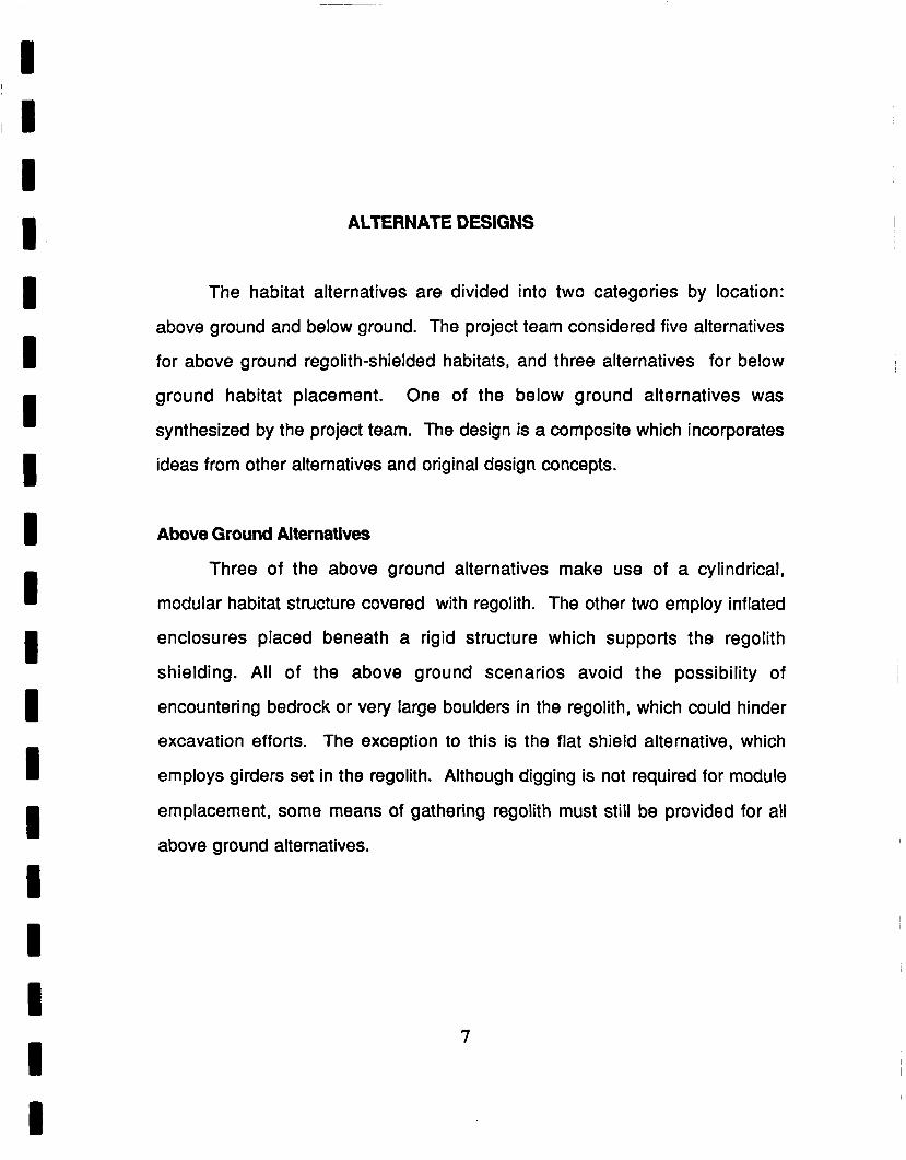
ALTERNATE DESIGNS
The habitat alternatives are divided into two categories by location:
above ground and below ground. The project team considered five alternatives
for above ground regolith-shielded habitats, and three alternatives for below
ground habitat placement. One of the below ground alternatives was
synthesized by the project team. The design is a composite which incorporates
ideas from other alternatives and original design concepts.
Above Ground Alternatives
Three of the above ground alternatives make use of a cylindrical,
modular habitat structure covered with regolith. The other two employ inflated
enclosures placed beneath a rigid structure which supports the regolith
shielding. All of the above ground scenarios avoid the possibility of
encountering bedrock or very large boulders in the regolith, which could hinder
excavation efforts. The exception to this is the flat shield alternative, which
employs girders set in the regolith. Although digging is not required for module
emplacement, some means of gathering regolith must still be provided for all
above ground alternatives.
7
I I I I I I I I I I I I I I I I I I I
8
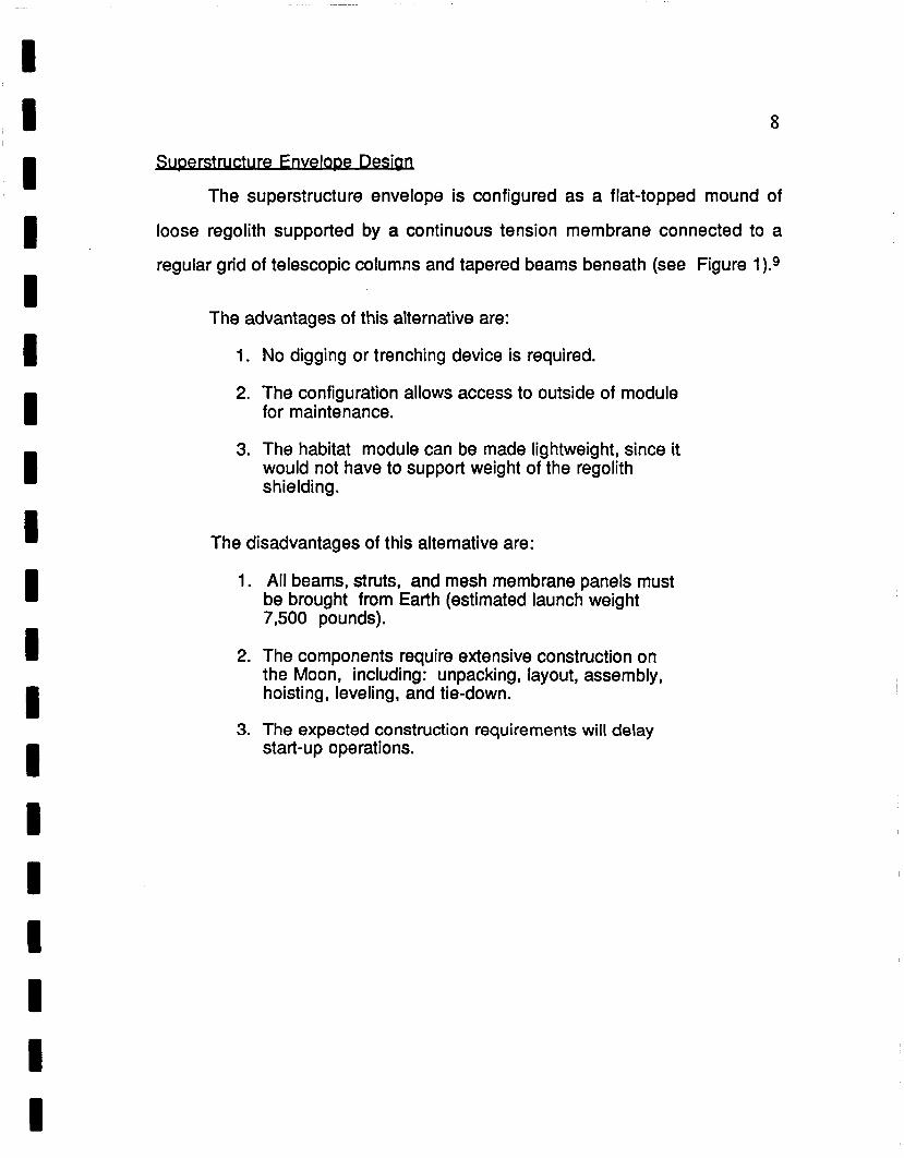
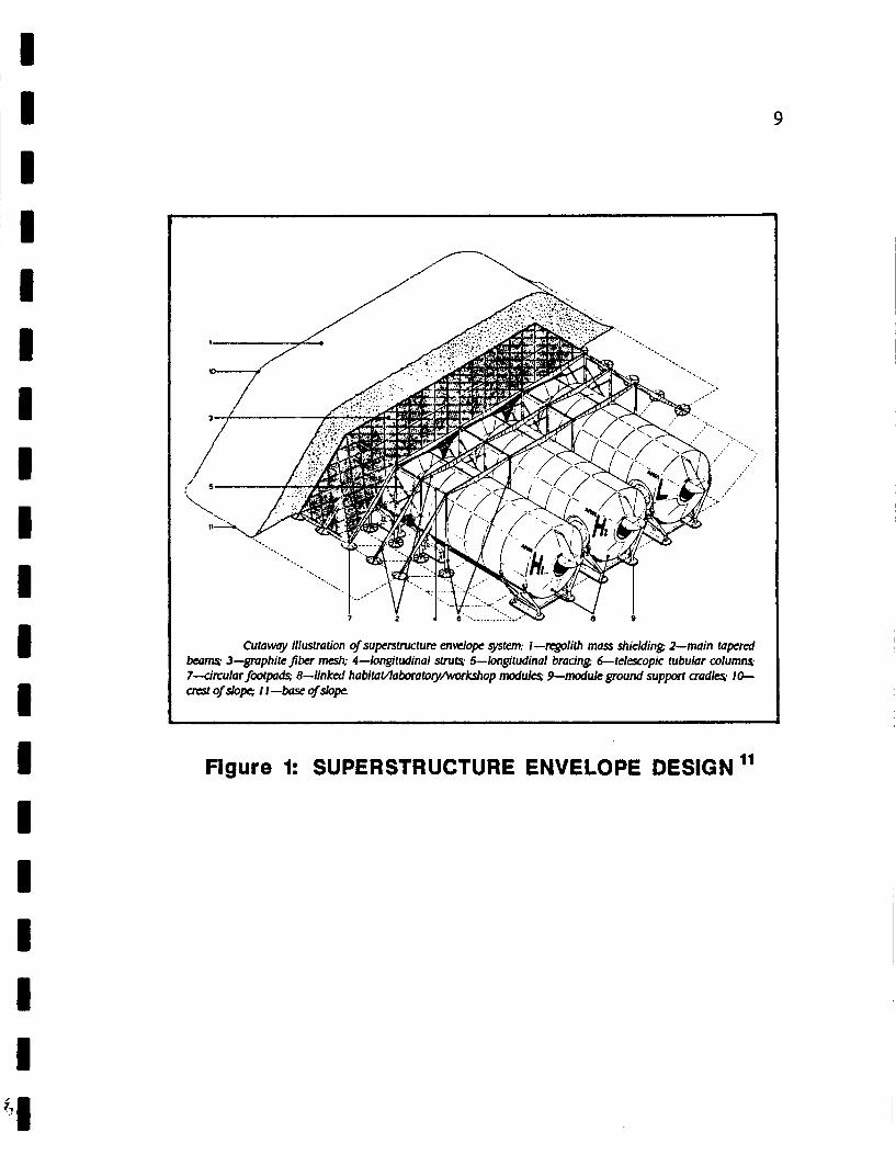
Derstrucwe F:gveloDe Design
The superstructure envelope is configured as a flat-topped mound of
loose regolith supported by a continuous tension membrane connected to a
regular grid of telescopic columns and tapered beams beneath (see Figure 1).9
The advantages of this alternative are:
1. No digging or trenching device is required.
2. The configuration allows access to outside of module for maintenance.
3. The habitat module can be made lightweight, since it would not have to support weight of the regolith s h ie Idi ng .
The disadvantages of this alternative are:
1. All beams, struts, and mesh membrane panels must be brought from Earth (estimated launch weight 7,500 pounds).
2. The components require extensive construction on the Moon, including: unpacking, layout, assembly, hoisting, leveling, and tie-down.
3. The expected construction requirements will delay start-up operations.
I I I I I I I I I I I I I I I 1 I 1
A I
b
Figure 1: SUPERSTRUCTURE ENVELOPE DESIGN l1
9
.... . ... . .
Cutaway illustration of superstructure enwlope system: I--regolith mass shielding 2-main tapered beams 3-graphite jber mesh; 4-longitudinal struts. 5-longitudinal bracing 6-telescopic tubular columns. 7--circular footpads 8-linked habitavloboratoyhrkshop modules 9 - d u l e ground support cradle 10- aesl of s l O R I I-base of slope.

I I I I I I I I I I I I I I I I 1 I I
10
Shield With I n f w d S-ura
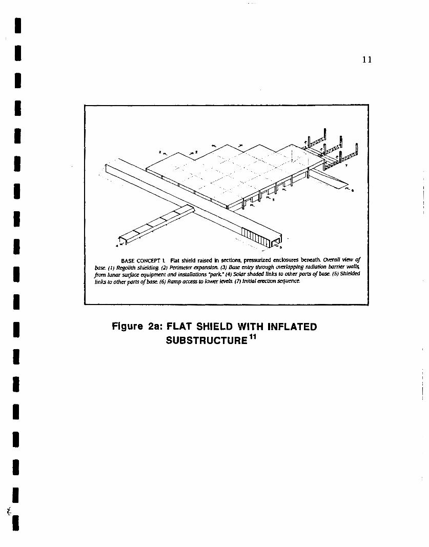
There are two parts to this design configuration: pressurized enclosures
beneath radiation shielding canopies. The structure supporting the regolith
consists of floors resting on lattice girders connected to columns and erected by
pneumatic jacks. The pressurized enclosures can be made to whatever shape
and size will fit under the shield (see Figure 2a).”
The advantages of this alternative are:
1. No digging or trenching device is required.
2. The design can be configured to provide large volumes of habitable space per kilogram of launch weight.
3. The pressurized enclosure weighs less than a habitat module, which reduces transportation requirements.
The disadvantages of this alternative are:
1. Girders must be placed and anchored, which could pose construction difficulties.
2. Pneumatic jacks are required to raise the roof of the structure.
3. All life support equipment and other machinery must be brought into the enclosure after it has been erected.
11
BASE CON- 1. flat shield raised in sections, pressurized enclosures beneath. Overall View of base. ( I ) Regolith shielding. (2) Perimeter expansion. (3) Base entry through mrlapping radiation bam'er wlls porn lunar sugace equipment and installations pork' (4) Solar shaded links to other parts of base. (5) Shielded links to other prts of base. (6) Ramp acccs lo lower levels (7) Initial erection sequence
Figure 2a: FLAT SHIELD WITH INFLATED SUBSTRUCTURE l1
I I
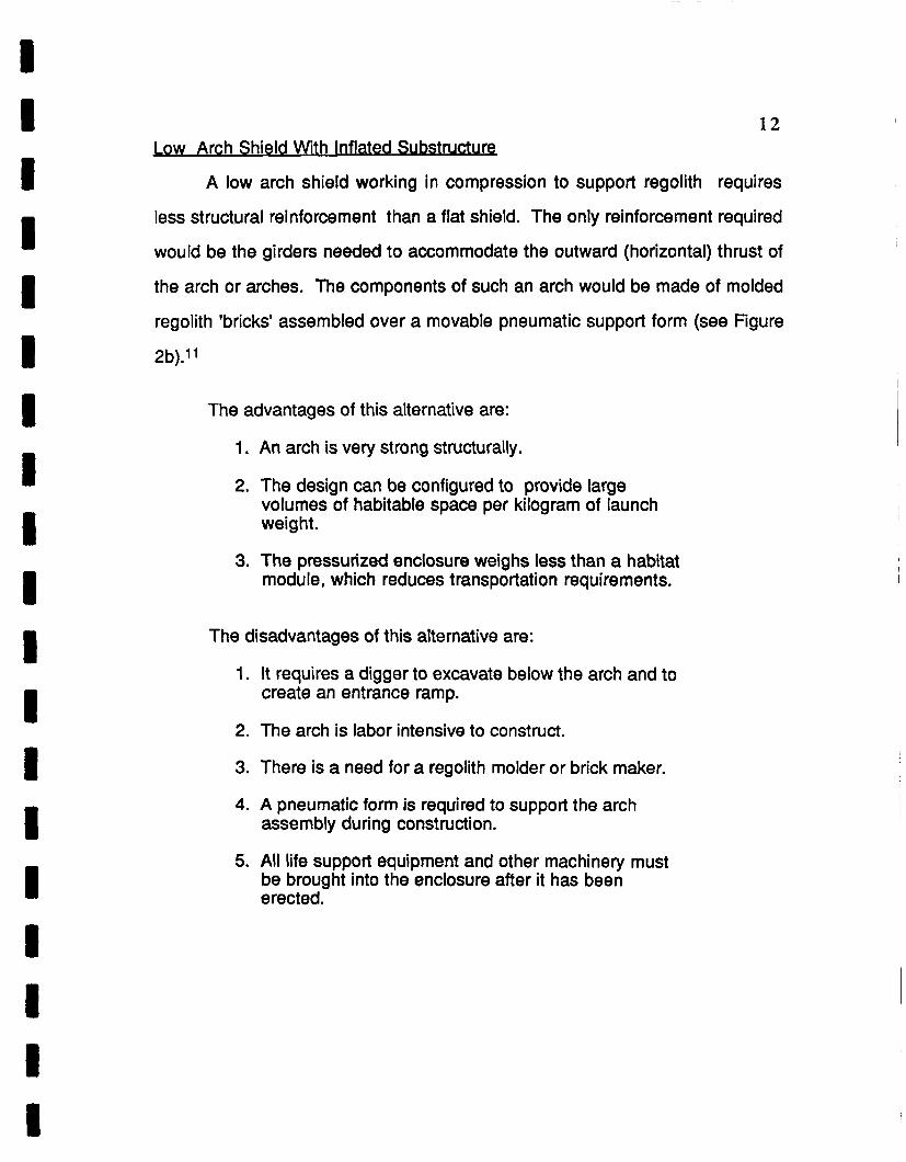
12 Low Arch Shield With Inflated Substructu re
A low arch shield working in compression to support regolith requires
less structural reinforcement than a flat shield. The only reinforcement required
would be the girders needed to accommodate the outward (horizontal) thrust of
the arch or arches. The components of such an arch would be made of molded
regolith 'bricks' assembled over a movable pneumatic support form (see Figure
2b).11
The advantages of this alternative are:
1. An arch is very strong structurally.
2. The design can be configured to provide large volumes of habitable space per kilogram of launch weight.
3. The pressurized enclosure weighs less than a habitat module, which reduces transportation requirements.
The disadvantages of this alternative are:
1. It requires a digger to excavate below the arch and to create an entrance ramp.
2. The arch is labor intensive to construct.
3. There is a need for a regolith molder or brick maker.
4. A pneumatic form is required to support the arch assembly during construction.
5. All life support equipment and other machinery must be brought into the enclosure after it has been erected.

I I I I I I I I B I I I I I i i I
'2 ,: I I
13
BASE CONCEPT n. b w arch shield using moulded regolith components assembled over temporary, movable pneumatic support form, pressurized enclosures beneath. General view of base ( I ) Regolith shielding. (2) Interlccking moulded q o l i t h a M components All components identical dimensions (3) Movable pneumatic /om supporting arch assembly. (4) Aluminum IatUce gitzien to accommodate outwad thrust of a M a Girdas assembledjlot on sur/oe with short wmponents and anchorrd to surfoce with vemcal p f m or wnndcfd with transvrrse cables at convenient widely space intends (5) Height inmsed whee q u i & by a m t i o n . (6) Expansion.
Figure 2b: LOW ARCH SHIELD WITH INFLATED SUBSTRUCTURE "
I I I I I B I B I 1 I i I I 8 I I I I
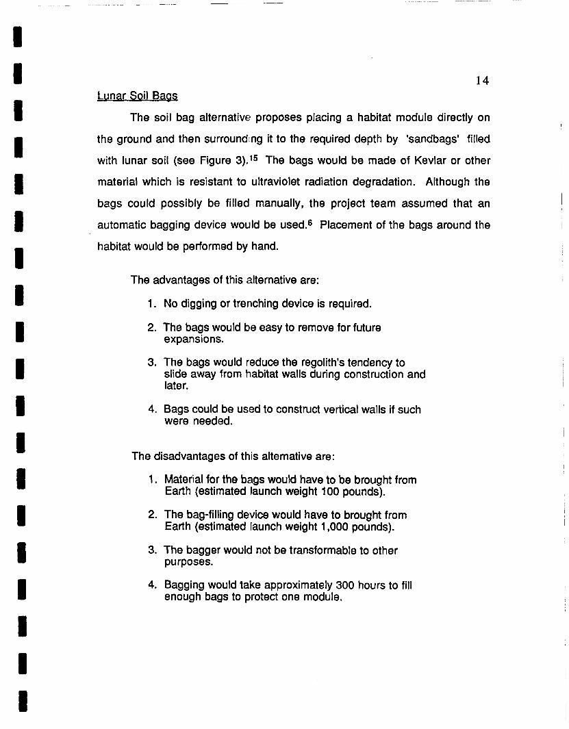
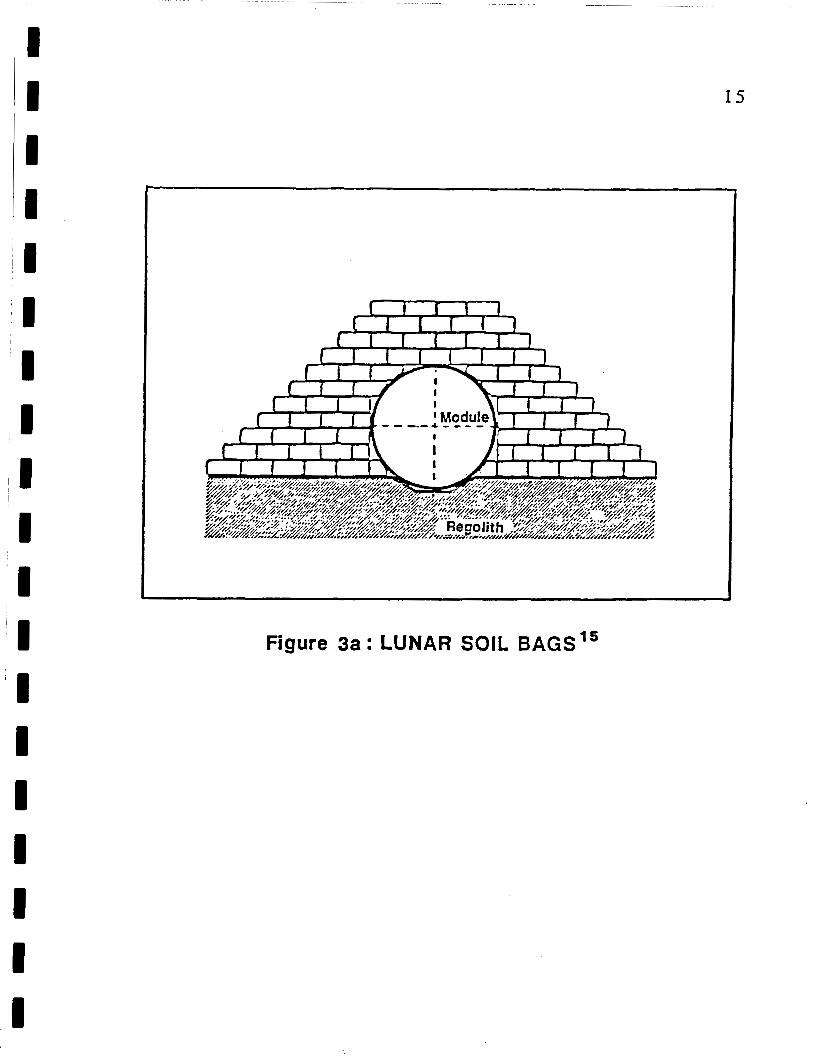
14 Lunar Soil Baas
The soil bag alternative proposes placing a habitat module directly on
the ground and then surrounding it to the required depth by 'sandbags' filled
with lunar soil (see Figure 3).'5 The bags would be made of Kevlar or other
material which is resistant to ultraviolet radiation degradation. Although the
bags could possibly be filled manually, the project team assumed that an
automatic bagging device would be used? Placement of the bags around the
habitat would be performed by hand.
The advantages of this alternative are:
1. No digging or trenching device is required.
2. The bags would be easy to remove for future expansions.
3. The bags would reduce the regolith's tendency to slide away from habitat walls during construction and later.
4. Bags could be used to construct vertical walls if such were needed.
The disadvantages of this alternative are:
1. Material for the bags would have to be brought from Earth (estimated launch weight 100 pounds).
2. The bag-filling device would have to brought from Earth (estimated launch weight 1,000 pounds).
3. The bagger would not be transformable to other purposes.
4. Bagging would take approximately 300 hours to fill enough bags to protect one module.
I 15
Figure 3a: LUNAR SOIL BAGS”
I 'I
'I I I I I I I
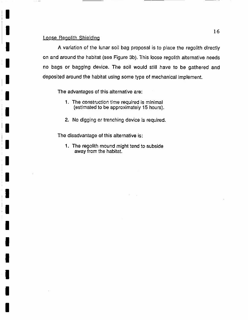
16 Loose Reaolith Shieldinq
A variation of the lunar soil bag proposal is to place the regolith directly
on and around the habitat (see Figure 3b). This loose regolith alternative needs
no bags or bagging device. The soil would still have to be gathered and
deposited around the habitat using some type of mechanical implement.
The advantages of this alternative are:
1. The construction time required is minimal (estimated to be approximately 15 hours).
2. No digging or trenching device is required.
The disadvantage of this alternative is:
1. The regolith mound might tend to subside away from the habitat.

17
. . . .. * * . .
Figure 3b: LOOSE REGOLITH SHIELDING
I I I
1 8
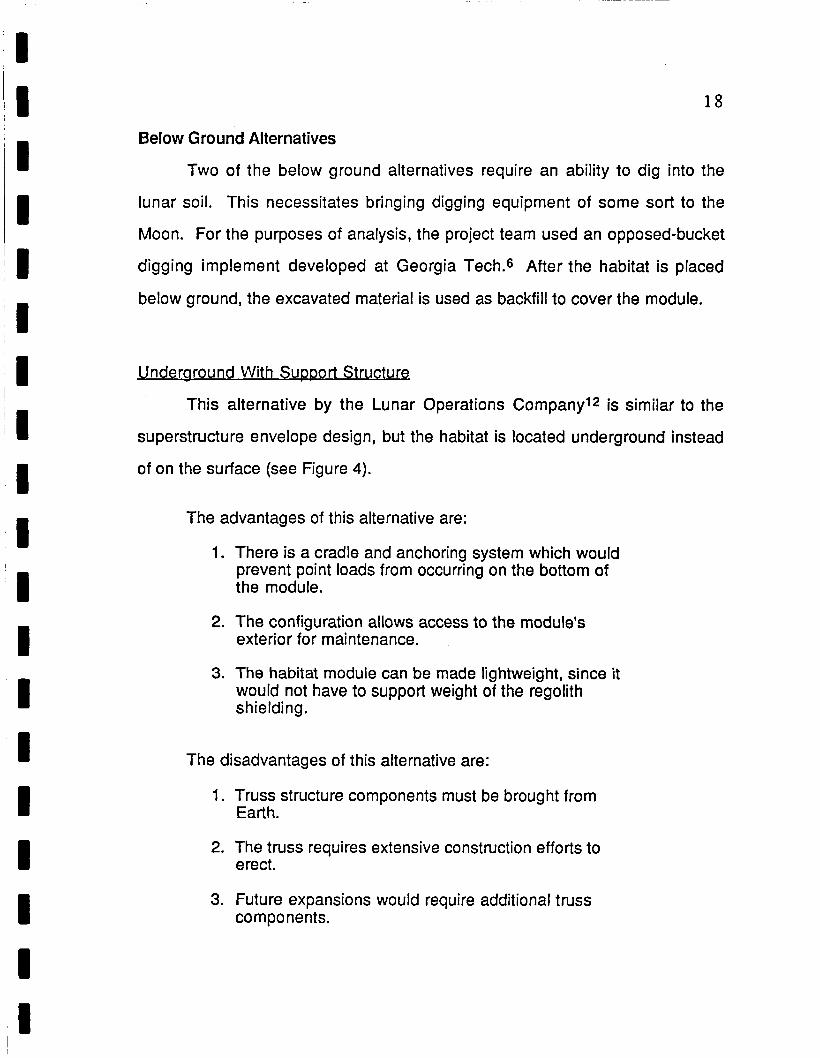
Below Ground Alternatives
Two of the below ground alternatives require an ability to dig into the
lunar soil. This necessitates bringing digging equipment of some sort to the
Moon. For the purposes of analysis, the project team used an opposed-bucket
digging implement developed at Georgia Tech? After the habitat is placed
below ground, the excavated material is used as backfill to cover the module.
Underaround With Support Structure
This alternative by the Lunar Operations Company12 is similar to the
superstructure envelope design, but the habitat is located underground instead
of on the surface (see Figure 4).
The advantages of this alternative are:
1. There is a cradle and anchoring system which would prevent point loads from occurring on the bottom of the module.
2. The configuration allows access to the module's exterior for mai n te nance.
3. The habitat module can be made lightweight, since it would not have to support weight of the regolith shielding .
The disadvantages of this alternative are:
1. Truss structure components must be brought from Earth.
2. The truss requires extensive construction efforts to erect.
3. Future expansions would require additional truss components.

I I I I I I I I I I I I I I I I I I I
19
OVERBURDEN
CONDARY FRAME
W
Figure 4: UNDERGROUND WITH SUPPORT STRUCTURE’*

I I I I I II
I II II
I 'I II I I I I I
!I
~'
20
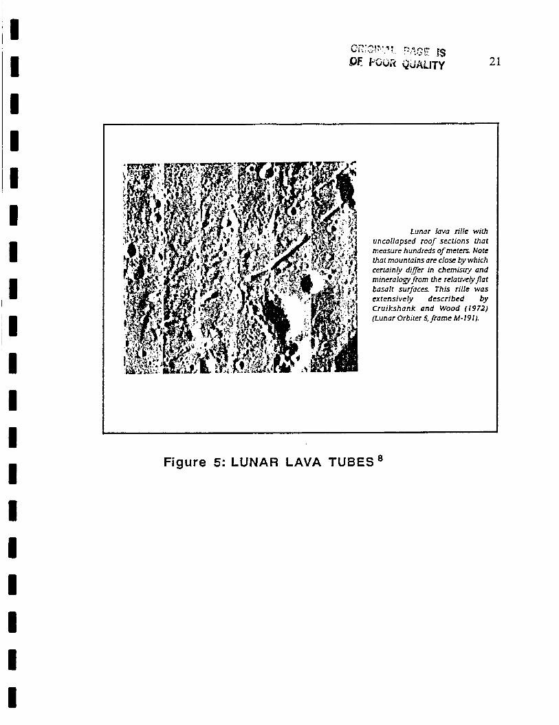
Lunar Lava Tubes
Natural caverns occur on the Moon in the form of lava tubes, which are
drained conduits of subsurface lava rivers? The tubes offer preformed
structures that are deep enough to provide natural protection from radiation and
micrometeorite impact (see Figure 5). The research outpost in a lava tube is
envisioned to be a modular habitat, set onto guide rails three times its length.
The rails are the only site preparation needed, and allow the habitat to be slid
into the tube under the uncollapsed roof section.
The advantages of this alternative are:
1.
2.
3.
4.
5.
No support structure is required, which reduces transportation requirements and construction efforts.
There is a constant thermal environment, estimated to be -20 degrees Celsius.
No digging or trenching is required.
The habitat module can be made lightweight, since it would not have to support weight of the regolith shielding.
No hauling and placing of regolith is needed.
The disadvantages of this alternative are:
1. The tube may be hard to access (Le., all materials will have to be lowered and raised to and from the tube).
2. As yet no lava tubes have been explored on the Moon.
3. The lava tubes do not offer flexibility of site selection.
I ' I I I
I I
I
I I I I I I
21
Lunar lava rille with uncollapsed roof sections that measure hundreds of meten Note that mountains are close by which certainly direr in chemistiy and mineralogy from the relativeiyj7at basalt surfaces. This rille was extensively described by Cruikshank and Wood (1972) (Lunar Orbiter 5. frame M-191).
Figure 5: LUNAR LAVA TU8ES8
I

I I I I :I I 1 I I I a
22
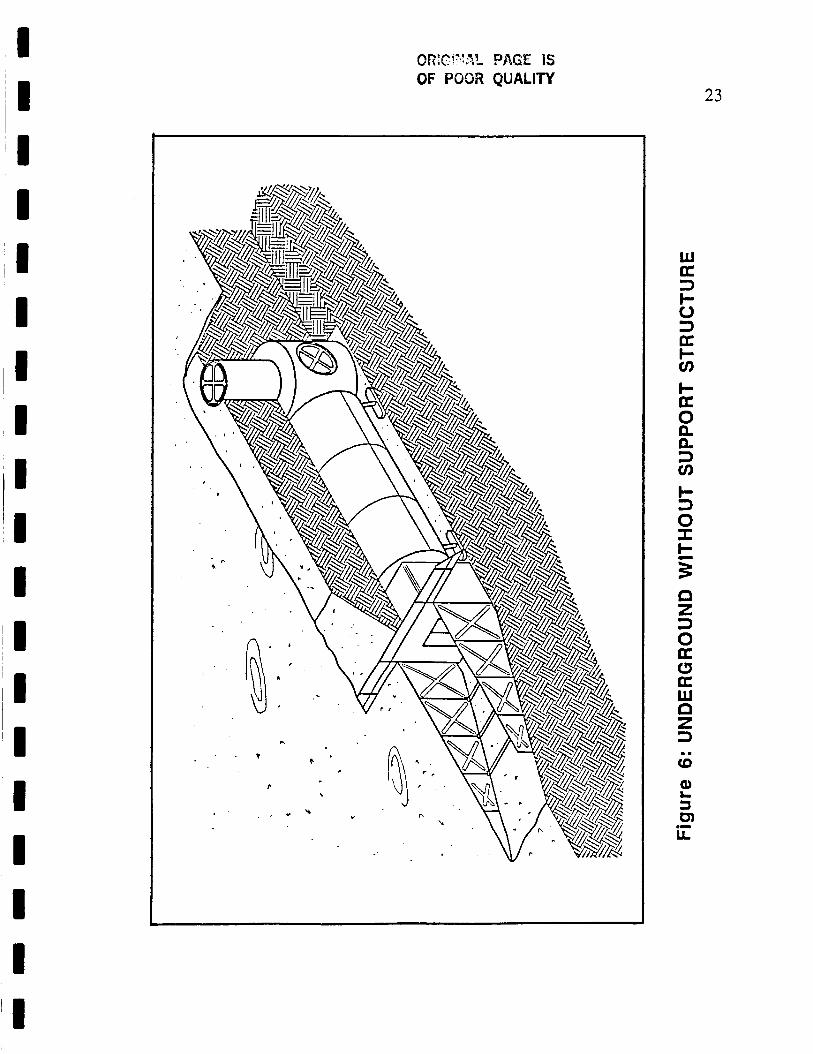
underaround Without Sup~ort St ructure
The module is buried in a trench so that its roof is 0.5 meters above
ground level. Primary access is achieved through an airlock, and an escape
exit is provided for emergency use (see Figure 6).
The advantages of this alternative are:
1. No regolith support structure is required.
2. Placing the module close to the surface reduces the volume of excavation required.
3. Access by means of a ramp provides for ease of entrance and exit.
4. A habitat with built-in reinforcement avoids construction requirements and the potential for associated problems on the Moon.
5. The module is equipped with hydraulic legs which facilitate leveling and prevent point loads from occurring on the bottom of the module.
The disadvantage of this alternative is:
1. It is not easily adapted to provide large volumes of habitable space.
I I I I I
L
b
. .
23
W U 3 I- u 3 U I- u)
I- a 0 e e 3 u)
I- 3 0 I I- 5 n 2 3 0 a c3 a W n z 3
CD
a 3 c31
LL
.. L
.I
I I I I I I I II 11 ‘I I II I I I 1 I I I
METHOD OF ANALYSIS
During the research stage of the project, the team assembled a set of
quantitative attributes for each alternative. The attributes include estimates for
the volume of excavation required, expected construction time, and the weight
of equipment to be brought from Earth. The attributes are presented in Table B1
of Appendix B, along with supporting descriptions and references.
Each alternative was analyzed according to how well it satisfied the
eleven identified design criteria. The analysis was performed by assigning a
weighting factor to each criterion, after which a decision matrix was used to
determine a numerical rank for each alternative. The team used the quantitative
data to aid in assigning decision matrix rating factors. In order to assess the
sensitivity of the analysis method, three different weighting schemes were
employed. The weighting factors and decision matrices used are found in
Appendix A. The results are given in Table 1 on page 25.
24

I
3B)LOOSE REGOLITH SHIELDING
25
4 3 2
'I I I 'I
516iJRIES WITHOUT SUPERSTRUCTURE ENVELOPE
!I I I I I I I
2 2 2
Table 1: SUMMARY OF DECISION RESULTS
RANKING I
m a ALTERNATIVES ABOVE GROUND 1 1 SURFACE ASSEMBLED
SUPERSTRUCTURE ENVELOPE
2 A l F L A T SHIELD
2B)DOME W I E L D II 1 1
I I I 1
3 A ) S O I L SAG SHIELDING II 1 1 1 l 5 I 6 l 4 II I 1
EELOW G73UND 4)BUk' IE3 WITH II 1 1
SUPERSTRUCTURE ENVELOPE 11 3 7 1 5
I I ' I ' I '

I I I
I I I I I I 1 I I
I
I
PROJECT SOLUTION
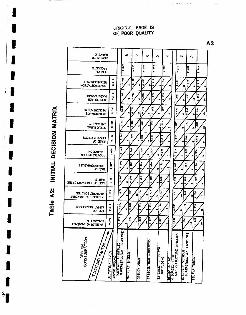
In all three cases, the lava tube alternative received the highest ranking
as the best design solution. However, there is a serious drawback to selecting
lava tubes as the best method of protecting lunar outpost inhabitants. Only a
few lava tubes are recognized, and none have been explored. Because no
suitable tubes are currently identified, the project team chose to develop the
second-ranked alternative, the buried module without a regolith support
structure.
This alternative is a composite design developed by the project team to
best satisfy the desired design criteria. The design consists of a cylindrical
habitat structure, an airlock with attached trench walls, and a module configured
for emergency escape and future habitat expansions. The design is shown in
Figure 7. The design details were developed as outlined in step five of the
design methodology section, and are presented below.
Assumptions
The project team assumed there would be equipment available for
digging and lifting material on the Moon. Specifically, previous USRA teams
have developed a lunar crane5 and digger.6 Also, an all-terrain device known
as the Skittefl has been developed to provide mobility for the crane, digger, and
other equipment. The Skitter is also assumed to be available for lunar
construction.
26

I I 8 27
ESCAPE A M I EXPANSION MODULE
~I 1 I I I 8 ~I
Figure 7: MODULE LAYOUT FOR FINAL DESIGN

I I I 'I 'I I
II I II 11 I I I I 1 I I I I
I
28 Recommendation of Site Selection
Sites which have been previously explored offer the advantage of
familiarity with local terrain and soil conditions. But because there is so much to
learn about the Moon, the team recommends that an unexplored site be
chosen for a research outpost. Specifically, we recommend that any site
selected should have proof that there are lava tubes within reach. The analysis
results indicate that situating a lunar base inside a lava tube would be a most
advantageous alternative. Consideration should especially be given to a
location on the lunar limb (the visible edge of the Moon's near side). Such a site
would offer proximity to the Moon's far side. The Moon's far side is shielded
from the radio noise of Earth, which makes it desirable for radio astronomy
research.
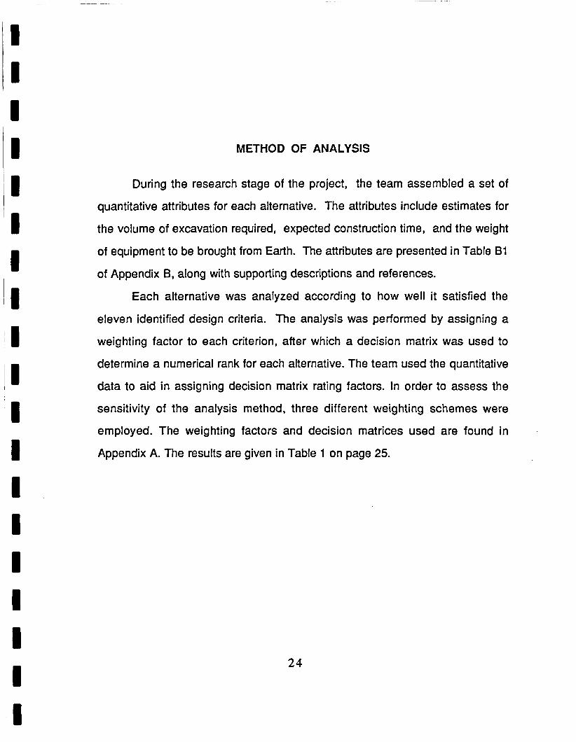
Protective Structure Configuration Outline
Three and one half meters (11.5 feet) of regolith cover the habitat
module. This depth is enough to provide adequate shielding against all GCR
and SEP.13 The habitat and support modules are seated in a trench that is
approximately 35.6 meters long by 4.5 meters wide by 4.0 meters deep (see
Figure 8). Four hydraulic legs support the habitat and allow for ease of
placement and leveling.
An airlock with attached ramp walls provides primary access to the
habitat module. The walls fold down to conserve space during transport, and
can be unfolded by hand once the airlock is in place. The walls are designed to
shore up the trench, and are formed with X-shaped corrugations to increase
I I
29
I All dimensions in meters
Figure 8: TRENCH DIMENSIONS

I I I I I I I I iI I 'I I I I I I I I I
30
their stiffness. Thin braces placed across the ramp floor provide additional
strength.
An emergency exit and expansion module is located opposite of the
airlock. Escape is accomplished through a vertical tube with ladder rungs
leading to the surface. The top of the vertical tube provides a 'yardstick' during
construction to indicate the height required of the regolith mound. The module
is envisioned as having a pressurized closet containing spare pressure suits. In
the event of a fire inside the habitat, the crew could get into the closet and vent
out the habitat's air, which should extinguish the blaze. The emergency module
is also configured with side ports to allow for future habitat additions.
Material Selection
A lightweight titanium alloy such as Ti-6AI-4V is recommended for the
folding ramp walls. This alloy is a readily available aerospace material, and is
recommended because it will keep the launch weight low. All moving joints
must have a protective coating such as Teflon, since bare metal surfaces will
cold vacuum weld upon contact. Teflon has the added advantage that it does
not degrade when exposed to ultraviolet radiation.
Structural Integrity Considerations
All of the modules must be must be made strong enough to withstand the
weight of the regolith mass shielding. Using an average regolith density of
1750 kilograms per cubic mete?, the 3.5 meter of soil covering will produce a
pressure of approximately 10 kiloPascals (kPa) per square meter. By way of
comparison, a pressure of one atmosphere is equal to approximately 101 kPa.

I I I I I I I I I I
, I I I I I I I I
3 1
Although the habitat's internal pressure will exceed the expected
external pressure, all modules should be designed to withstand the regolith's
weight unaided. This will prevent collapse of the structure due to a loss of
internal pressure.
Construction Sequence Outline
The lunar construction operation will consist of digging the trench,
placing and leveling the modules, deploying the ramp walls, and covering the
modules with backfill. The modules and construction equipment should be
landed ahead of the crew. If landing-related problems occur, the mission can
be aborted without endangering human lives. Equipment unpacking will begin
after the crew has landed. A heavy-lift crane attached to the equipment lander
will facilitate the unpacking and it can be used to place the module into the
trench.
Heat Transfer Considerations
The lunar soil is a poor conductor of heat. The thermal conductivity of
Moon soil ranges from 0.0021 watts per meter Kelvin (w/m-k) at the surface to
2.077 (w/m-k) at a depth of twenty feet? At this point it is unknown how much
heat will be generated inside the habitat by onboard electronics and the crew
members themselves. Once the expected heat transfer requirements have
been determined, some form of radiant heat exchanger will have to be devised,
since the soil covering will act as a thermal insulator.
'I
32
Maintenance Aspects
Most of the habitat structure is located below surface level, so the regolith
mound should have little tendency to subside. The presence of the ramp walls
will prevent the trench wall from collapsing. Thus little or no maintenance of the
regolith shield and ramp is expected.
The exterior of the structure will be covered with soil, making it
inaccessible for outside maintenance. Therefore all planned maintenance of
the habitat must be designed to be accomplished from inside. This aspect is
actually desirable to exterior maintenance, where the need for a space suit
imposes severe restrictions on mobility and sensitivity. Interior maintenance
can be performed in the 'shirtsleeve' environment of the habitat.
Future Expansion
The emergency exit module has five ports, three of which can be used to
attach additional habitats or other modules. When it is desired to add on to the
base, only the regolith covering the end of the structure would need to be
removed.
iI I I I 'I I I

CONCLUSIONS AND RECOMMENDATIONS
The team's original design satisfies all the identified design criteria. The
structure will adequately protect its inhabitants from both galactic cosmic and
solar radiation, as well as micrometeorite impacts.
The project team believes it is more advantageous to build all module
components so that they are strong enough to support the weight of the regolith
shielding. Adding this strength to the modules greatly simplifies lunar
construction by eliminating the need to assemble a truss structure at the site.
It is highly recommended that this initial operations habitat be provided
with complete radiation protection. Future additions to the base can be
provided with less regolith shielding protection. Reducing the regolith
overburden will lower the structural strength requirement, which will decrease
the transport weight of additional modules. In the event of a solar flare or any
other radiation increase, the initial habitat can be used as a 'storm cellar' until
the radiation has decreased to a tolerable level.
The project team recommends that future development of this project
should include a detailed design of all structures (Le., the airlock, habitat, and
emergency escape modules).
A recommended future project would be the analysis and development of
protective structures for a post-outpost base that is permanently occupied and at
least partially self-sufficient.
ORlGlNAL PAGE IS OF POOR QUALITY
3 3
REFERENCES
1. Adams J. H. and Shapiro M. M., Irradiation of the Moon by Galactic Cosmic Rays and Other Particles, In Lunar Bases and Space Activities of the 21st Century. Wendell Mendell (editor) (1985) Lunar and Planetary Institute, Houston, Texas, p. 31 5.
2. Bilby C. , Excerpts from reports on radiation in space, Department of Aerospace Engineering, The University of Texas at Austin, Received February 1988.
3. Georgia Institute of Technology Final Report, An Automated, Lunar Brick- Making Device. (June 1987) Advanced Missions Space Design Program, NASNU nive rsity.
4. Georgia Institute of Technology Final Report, Detail Design of a Three- Legged Mobile Platform. (June 1987) Advanced Missions Space Design Program, NASNUniversity.
5. Georgia Institute of Technology Final Report, Lunar Lifting Implement. (June 1987) Advanced Missions Space Design Program, N ASNU n ive rs ity .
6. Georgia Institute of Technology Final Report, Opposed-Bucket Lunar Digging Implement. (June 1 987) Advanced Missions Space Design Program, NASNU niversity.
7. Guest J.E. and Greeley R., Geoloav on the Moon. (1977) Wykeham Publications Ltd., London and Basingstoke, p. 141.
8. Horz F., Lava Tubes: Potential Shelters for Habitats. In Lunar Bases a nd SDace Activities of the 21st Centuw. Wendell Mendell (editor) (1985) Lunar and Planetary institute, Houston, Texas, p. 405.
9. Kaplicky J. and Nixon D., A Surface-Assembled Superstructure Envelope System to Support Regolith Mass-Shielding for an Initial-Operational- Capability Lunar Base. In Lunar Bases and Space Activities of the 21st Century. Wendell Mendell (editor) (1 985) Lunar and Planetary Institute, Houston, Texas, p. 375.
34

I I I I I
10.
17.
'I I I I I 1 I 1
12.
13.
14.
15.
3 5 REFERENCES (Continued)
Langham W. H. (editor) (1970) Radiation Protection Guides for Space- Mission and Vehicle-Design Studies Involving Nuclear Systems. Radiobiological Advisory Panel, Committee on Space Medicine, Space Science Board, NAS/NRC, Washington, D.C.
Land P., Lunar Base Design. In Lunar Bases and SDace Activities of the Zlst Ce ntury. Wendell Mendell, (editor) (1 985) Lunar and Planetary Institute, Houston, Texas, p. 363.
Lunar Operations Company, A Final Design Review for a Bootstrap Lunar Base. (1 987) Department of Aerospace Engineering, The University of Texas at Austin, Austin, Texas.
Silberberg R., Radiation Transport of Cosmic Ray Nuclei in Lunar Material and Radiation Doses, Lunar Bases and Space Activities of the 21st Century. Wendell Mendell, (editor) (1 985) Lunar and Planetary Institute, Houston, Texas, p. 663.
Taylor S. R., Lunar Science: A Post-Apollo View. (1975) Pergamon Press Inc., Elmsford, New York, p. 88.
Ximenes, S. W. , Design and Development of Transport Mechanisms for "Bagging" Lunar Soil for Use As Radiation Shielding. (1 985) Center for Experimental Architecture, College of Architecture, University of Houston, Houston, Texas.

APPENDIX A
Analysls of Alternatives by Decision Matrix

I D ANALYSIS OF ALTERNATIVES BY DECISION MATRIX
8
1 1
A decision matrix is a tool used as an aid in the decision making process.
Decision matrices are usually employed when a selection must be made from
several possible design alternatives. To use a decision matrix, a set of design
criteria must be identified. Every criterion is assigned a weighting factor
determined by its relative importance in the set. Each alternative is then
assigned rating factors based on the designer's judgement of how well it
satisfies the design criteria. The products of the weighting factors and rating
factors are then summed to assign a numerical rating to each alternative. The
alternative with the highest sum of products is ranked number one, that is, the
'best' possible alternative.
Weighting factors for the criteria were determined using the method of
pairs. The method is a sequential process by which every possible pair of
criteria is compared. A tally mark is given to the criterion considered to be of
greater importance. The total number of marks each criterion received is then
divided by the total number of tally marks to obtain a weighting factor between
zero and one.
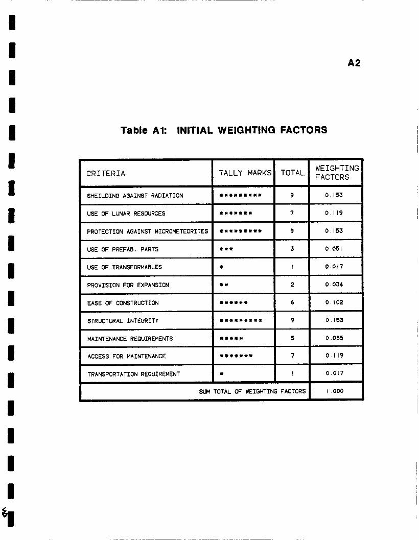
Table A1 outlines the results of the initial method of pairs analysis. The
weighting factors from Table A1 were used in an initial decision matrix to
determine the numerical rank of each alternative. The decision matrix is
presented in Table A2.
A2
SHEILDING AGAINST RADIATION
USE OF LUNAR RESOURCES
Table Al: INITIAL WEIGHTING FACTORS
I********
*******
CRITERIA
USE OF PREFAB. PARTS
USE OF TRANSFORMABLES
PROVISION FOR EXPANSION
I TALLY MARKS
***
* * *
STRUCTURAL INTEGRITY
MAINTENANCE REOUIREMENTS
PROTECTION AGAINST MICROMETEORITES I * * * * * * * * *
*********
I****
ACCESS FOR MAINTENANCE
TRANSPORTATION REQUIREMENT
EASE OF CONSTRUCTION I **I***
*******
*
WEIGHTING FACTORS TOTAL I
0 . I53 + 0.1 19
9 I 0.153
3 I 0.051
I I 0.017
2 I 0.034
0.102 + 0.153
6 I 0 .085
7 I 0.1 19
I I 0.017
SUM TOTAL OF WEIGHTING FACTORS 1 I ,000
uHGIY\~AL PAGE IS OF POOR QUALSn
A 3

A4
The project team employed two additional weighting schemes in order to
assess the validity of the initial decision results. The second weighting system
was devised so that the minimum transportation requirement criterion would be
equal in weight to the other top-ranked criteria (i.e., radiation and
micrometeorite shielding, and structural integrity). This weighting scheme was
developed at the suggestion of NASA's Dr. John Allred, and is presented in
Table A3.
The weighting factors from Table A3 were used with the original rating
factors to construct the decision matrix shown in Table A4.
The final decision matrix was constructed with all criteria weighted
equally. The results contain a tie for second place, and are presented in Table
A5.

I ‘ I
SHEILDING AGAINST RADIATION
USE OF LUNAR RESOURCES
A5
******** 8
****** 6
Table A3: WEIGHTING FACTORS WITH
TRANSPORTATION REQUIREMENTS EMPHASIZED
PROTECTION AGAINST MICROMETEORITES
USE OF PREFAB. PARTS
~
CRITERIA
******** 8
* * 2
~~ 1 TALLY MARKS
~
USE OF TRANSFORMABLES
PROVISION FOR EXPANSION
EASE OF CONSTRUCTION
*
*
*****
STRUCTURAL INTEGRITY
MAINTENANCE REQUIREMENTS
ACCESS FOR MAINTENANCE
******** 8
**+* 4
****** 6
I
I
5
TRANSPORTATION REQUIREMENT I ******** I 8
SUM TOTAL OF WEIGHTING FACTORS
~ ~
WEIGHTIf FACTORS
0. I40
0. IO5
0. I40
0.035
0.017
0.017
0.088
0. I40
0 I 070
0.105
0.140
I ,000

x K I
23 W P
ORIGINAL PAGE OS OF POOR Q U A L L n
A6

I I I I I I I I I I I I I I I 1 I I 9
A7
a 3 t3 w tn K 0 I- o u, a

I I I 1 I I I ' I I I I I I I I I 1 I I
APPENDIX B
Quantitative Attributes of Alternatives
I I ‘ I I I
II I
I ‘ I I ‘ I I I I I I I I I
B1
QUANTITATIVE ATTRIBUTES OF ALTERNATIVES
Volume of Regolith Excavation Required
The volume of regolith excavated is determined by the geometric shape
of the trench.
Volume of Regolith Required for Shielding
The regolith depth required for shielding is 3.5 meters. The total volume
of regolith required varies with each alternative due to surface area differences.
Construction Time
The construction time is estimated based upon the expected construction
sequence of each particular alternative. The sequences include unpacking,
layout, trenching, structure assembly, habitat placement, regolith gathering, and
regolith deposition.
Estimated Weight of External Support Structure
The weight of each support structure is estimated relative to the specified
weight of the surface assembled superstnrcture envelope alternative.9

i I I 1
B2 Estimated Weight of Additional Equipment Required
When available, the weight of additional equipment is cited from the
report on the specific device. Othewise, the weight is estimated based on
similar equipment found on Earth.
Total Weight Brought From Earth
The total weight represents the weight of additional equipment required
plus the weight of the external support structure, if any.

I I I I I
lI I
~I I ;I I I I I I 1 I I II
B3 ORIGINAL PAGE IS OF POOR QUALm

I I I I
APPENDIX C
Layout Drawings