radiation safety & nuclear gauge … safety & nuclear gauge training ... 5.3 in the event of...
TRANSCRIPT

RADIATION SAFETY & NUCLEAR GAUGE TRAINING
2018
Technical Training & Certification Program


Iowa Department of Transportation
Technical Training and Certification ProgramCourse Evaluation Sheet
As part of our continuing effort to improve the program, we ask that you please carefully fill out this evaluation sheet. Your responses are very important to us. We read each comment and consider your suggestions and feedback for future classes. Please use the back of the page if additional space is needed.
Course Name (Example: PCC I, AGG II): _______________ Course Instructor: ____________________
Location of course: What type of agency do you work for:(District or city): ____________________ a) DOT b) County or City c) Consultant d) Contractor e) Other
Were the instructor(s) effective in helping you learn? How could they be more helpful?
Were the instructional manuals helpful and user friendly? How could they be improved?
Is there a topic you would have liked to spend more time on? Less time on?
Do you feel prepared to work as a certified tech in this area?
What are one or two things you liked best about this class?
What are one or two things you would like to see done differently in this class?
Thank you!!!


15
IOWA DOT & ORGANIZATIONS
PHONE FAX ADDRESS NUMBER NUMBER CONTACT PERSONTechnical Training 515-233-7915 515-239-1092 Brian Squier - TTCP Coordinator& Certifi cation Program [email protected] 1 Materials800 Lincoln Way 515-239-1819 Emily Whaley - TTCP Coordinator Ames, Iowa 50010 [email protected] District 2 Materials 641-422-9420 641-422-9463 Kelli Arnburg428 43rd Street SW [email protected] City, Iowa 50401
District 3 Materials 712-239-4713 712-239-4970 Alex Crosgrove4621 US 75 North [email protected] City, Iowa 51108
District 4 Materials 712-243-7649 712-243-5302 Mike Magers2310 E. Seventh St. [email protected], Iowa 50022
District 5 Materials 641-472-3103 641-469-3427 Ellen DavidsonPO Box 843 [email protected] eld, Iowa 52556-0587
District 6 Materials 319-366-0446 319-730-1565 Lynn Gemmer5455 Kirkwood Blvd. SW [email protected] Rapids, Iowa 52404 Phone Number Fax NumberWesley Musgrove Construction & Materials Engineer 515-239-1843 515-239-1092Todd Hanson PC Concrete Engineer 515-239-1226 515-239-1092Mahbub Khoda Prestressed Concrete Engineer 515-239-1649 515-239-1092Kevin Merryman PC Concrete Field Engineer 515-239-1848 515-239-1092Kyle Frame Structures Group Manager 515-239-1619 515-239-1092 Curtis Carter Structures Field Engineer 515-239-1185 515-239-1092Chris Brakke Pavement Management Engineer 515-239-1882 515-239-1092Jeffrey Schmitt Bituminous Field Engineer 515-239-1013 515-239-1092Brian Gossman Chief Geologist 515-239-1204 515-239-1092Melissa Serio Soils & Grading Field Engineer 515-239-1280 515-239-1092Jeff DeVries District 1 Materials Engineer 515-239-1926 515-239-1943Keith Norris District 2 Materials Engineer 641-422-9421 641-422-9463Bill Dotzler District 3 Materials Engineer 712-239-4713 712-239-4970 Timothy Hensley District 4 Materials Engineer 712-243-7629 712-243-6788Bruce Hucker District 5 Materials Engineer 641-472-3103 641-469-3427Roger Boulet District 6 Materials Engineer 319-366-0446 319-730-1565

IOWADOT U
https://learning.iowadot.gov/
IOWADOT U is the Iowa Department of Transportation's learning management system.
This is where you register for classes and take web-based training. You can also print your
training records transcript here.
Step-by-step instructions are available at https://iowadot.gov/training/technical-training-and-
certification-program.
Your username and password for test.com and your username for IOWADOT U may, or
may not, be the same. Since you create both yourself, you can make them the same, or
different.
Below is a screenshot of the log-in screen. You might find it useful to record your username
and password below for future reference.

1
1 Table of Contents 1 Introduction to Nuclear Moisture Density Gauges .......................................... 3
1.1 How Radiation Makes Them Work .............................................................................. 3
1.2 Anatomy of a Gauge .................................................................................................... 4
1.3 Radiation Measurement: The Invisible Property ........................................................ 5
1.4 Gamma Ray Photon Radiation .................................................................................... 5
1.5 Neutron Radiation ....................................................................................................... 7
1.6 Safety Record ............................................................................................................... 7
2 Radiation Basics ................................................................................................ 8
2.1 Atoms, Elements, Isotopes and the Periodic Table ..................................................... 8
2.2 Radioactivity, Contamination, Radiation and Decay ................................................. 11
2.3 The Four Types of Radiation Emitted by the Gauge ................................................. 12
2.4 Radiation Decay & the Half Life ................................................................................. 14
2.5 Ionizing Radiation ...................................................................................................... 15
2.6 Radiation Measuring Units ........................................................................................ 15
2.7 Biological Effects of Radiation – Putting Radiation Exposure in Perspective............ 15
2.8 Background Exposure vs. Occupational Exposure .................................................... 17
2.9 Sources of Background Radiation.............................................................................. 18
2.10 Measuring Your Exposure ......................................................................................... 19
2.11 External vs. Internal Exposure ................................................................................... 19
2.12 Your Occupational Exposure Limits ........................................................................... 21
2.13 Realistic Annual Average Exposures .......................................................................... 21
3 Limiting and Tracking Your Exposure ............................................................ 22
3.1 ALARA –As Low As Reasonably Achievable ............................................................... 22
3.2 Tracking Your Exposure – Your TLD ........................................................................... 26
3.3 Agencies, Licensing, Regulations and Recordkeeping ............................................... 26
3.4 The Specific License ................................................................................................... 27
3.5 Enforcement .............................................................................................................. 27
3.6 Protecting the General Public, Property and Our Employees ................................... 27
3.7 The Radiation Safety Officer (RSO) ............................................................................ 27
4 Transportation and Storage of Gauges .......................................................... 28
4.1 A Step by Step HAZMAT Guide .................................................................................. 28
5 Emergency Procedures ................................................................................... 35
2
5.1 In the Event of Damage at the Worksite: .................................................................. 35
5.2 In the Event of Damage in an Auto Accident: ........................................................... 35
5.3 In the Event of Theft: ................................................................................................. 35
6 Gauge Operation .............................................................................................. 36
6.1 Standard Counts ........................................................................................................ 36
6.2 Moisture Content and Density of Soils (IM 334) ....................................................... 37
6.3 Asphalt Moisture and Density of Cold-in-Place Recycling (IM 504) .......................... 40
6.4 PCC Density (IM 358) ................................................................................................. 40
6.5 Some Possible Reasons for Errors in Gauges ............................................................ 41
6.6 Gauge Maintenance Basics........................................................................................ 42
7 Glossary ............................................................................................................ 43
Appendices
NUCLEAR MOISTURE-DENSITY GAUGE SAFETY PROCEDURES MANUAL
IM 206 NUCLEAR TEST EQUIPMENT
IM 334 DETERMINING MOISTURE CONTENT & DENSITY OF SOILS, BASES & SUBBASES WITH A NUCLEAR GAUGE
IM 358 DETERMINING PLASTIC DENSITY OF PORTLAND CEMENT CONCRETE WITH A NUCLEAR GAUGE
IM 504 COLD-IN-PLACE RECYCLING of HOT MIX ASPHALT (HMA) PAVEMENT

3
1 Introduction to Nuclear Moisture Density Gauges
1.1 How Radiation Makes Them Work Nuclear moisture density gauges have been in use for over thirty years. They offer the technician a quick and accurate means of determining density and moisture content of soils, asphalt and concrete. They all use essentially the same design and basic approach to determine these measurements.
Gauges consist of a radiation source that emits a directed beam of particles and a sensor that counts the received particles that are either reflected by the test material or pass through it.
By calculating the percentage of particles that return to the sensor, the gauge can be calibrated to measure the density and inner structure of the test material.
All moisture density gauges use two different radioactive sources to produce two different types of radiation. One of the radioactive sources, Cesium 137, emits gamma ray photon radiation to determine density, while the other radioactive source, Americium 241 (combined with non-radioactive Beryllium), emits neutron radiation to determine moisture content.
Annual radiation safety training is required for all individuals working with portable gauges, even if only transporting them.

4
As seen in this illustration, these sources are double encapsulated before being installed inside the gauge. This double encapsulation undergoes extensive integrity testing and is virtually impenetrable, forming a solid core of metal around the sources. The encapsulated source is then fused at the base of the metal source rod or embedded in the base of the gauge, giving the operator three levels of distinct metal shielding from the source.
The sources themselves have been solidified in a way that prevents them from leaking. Note the physical size of the density source bead – it is approximately half the size of a piece of rice. The moisture pellet is smaller than a baby aspirin. The final double encapsulated metal housing around these sources is about the size of a pencil eraser. Both sources have been laser fused inside the gauge, leaving no way to gain access.
1.2 Anatomy of a Gauge As seen in this depiction, gauges have a handle at the top of metal rods which are called source rods and depth rods. The handle at the top of the rods has a release mechanism that allows the source rod to be lowered out of the gauge into positions starting at the base of the gauge and continuing at predetermined notched positions below the surface. These notched positions can be readily seen along the spine of the depth rod. The notches are usually spaced 2 inches apart along a 12 inch rod, allowing the operator to choose the notch that matches the depth of the desired measurement.

5
1.3 Radiation Measurement: The Invisible Property
A gauge uses nuclear radiation to determine density and moisture. Radiation can be described as numerous disintegrations from unstable elements ejecting sub-atomic energy or particles from the element’s nucleus. Density and/or moisture measurements are achieved by counting the amount of radiation that can pass through matter to the gauge’s detector tubes.
The density source is sending out a constant and steady level of radiation. The detector tubes are receiving and counting this constant and steady level. Any material between the source and the detector tube will reduce the amount of radiation received. As the material becomes more compacted, more and more of the radiation is stopped by the material. You end up with fewer counts, which is interpreted as a higher density of the material.
The moisture source sends out a different type of radiation that must be slowed down before it can be counted. The hydrogen in moisture acts to slow down this radiation, which results in higher counts. The gauge interprets higher counts as a higher level of moisture under the gauge.
You can’t see or feel these types of radiation. But you must realize that the radiation is present and take precautionary steps to ensure that you keep yours, and everyone else’s, exposure to radiation at a minimum.
1.4 Gamma Ray Photon Radiation
The Cesium 137 (Cs137) density source, also known as the emitter, resides at the bottom of the source rod. Cs137 releases gamma ray photon radiation, which is used to measure density. When the operator pushes the start key the gauge detector tubes begin measuring the amount of radiation that is moving from the Cs137 source to the Geiger Muller tubes, at the opposite end of the gauge.
As compaction of the material under the gauge increases, more of the gamma ray radiation will be absorbed, unable to make it to the detector tubes to be counted. The gauge interprets lower counts as a higher density.
While in the safe (retracted) position inside the gauge, the Cs137 source is surrounded by a tungsten bio-shield that offers optimum shielding that gives extra protection to the operator. A tungsten spring-loaded sliding block closes shut below the source rod whenever it is retracted after a test. This completes the bio-shield around the source rod.
When a test (except PCC density tests) is completed, the operator should immediately lift the gauge by the handle. The handle features a safety design that retracts the source rod into the safe position before the gauge can be lifted off the ground.

6
The Two Types of Transmission
Direct transmission is typically used for a soils or a PCC bridge deck application. For soils testing,
an access hole is made with the drill rod and the source rod is lowered to a predetermined depth, up to 12 inches. To determine the density of plastic PCC, the source rod is lowered into the freshly placed concrete. Direct transmission is more accurate than backscatter transmission.
Backscatter transmission is typically used for asphalt tests. The first depth notch on the gauge is the backscatter position. This will open the sliding block and place the source rod at the base of the gauge and at the top of the testing surface (No access hole is drilled for a backscatter test).
The gamma ray photons will penetrate the material to a maximum depth of 3–4 inches before making their way to the Geiger-Mueller detector tubes at the far
side of the gauge.
7
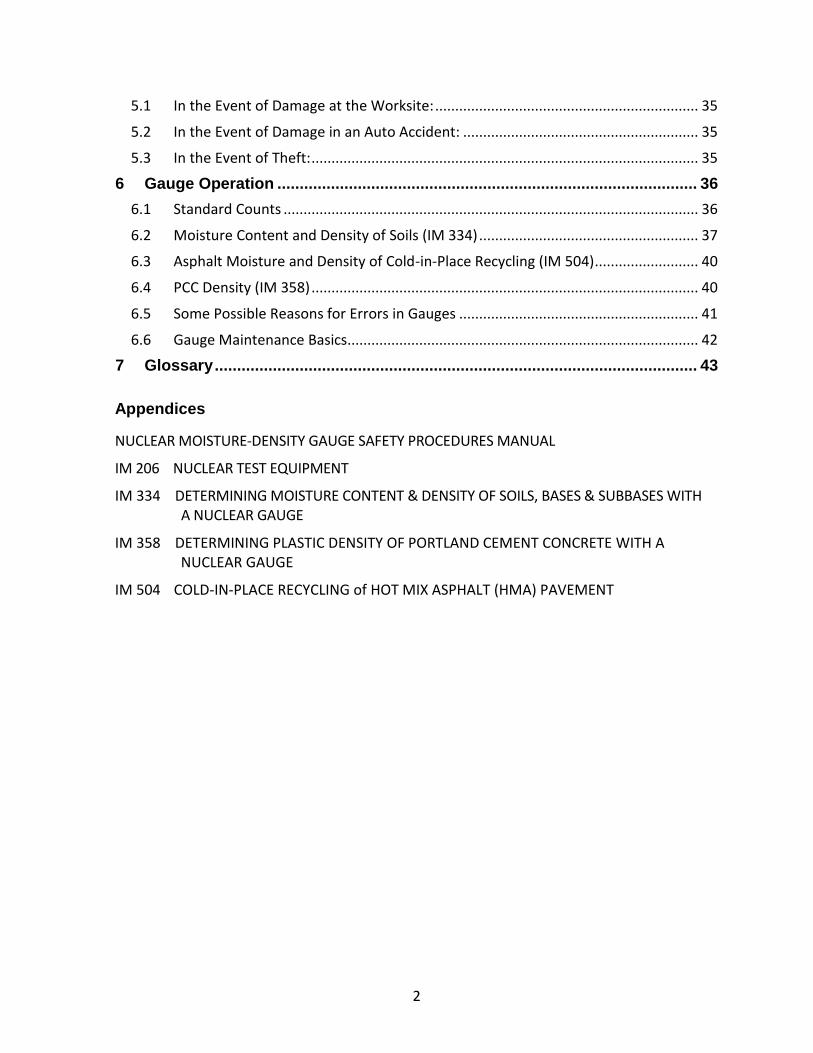
1.5 Neutron Radiation The Americium 241 (Am241) source permanently resides in the base of the gauge and is surrounded by additional shielding. Unlike the Cs137 in the source rod, it never releases out of the gauge. The Am241 source releases neutron radiation to measure moisture.
The neutron is emitted in a form known as a “fast neutron”.
The Helium 3 detector tube resides next to the source. But the detector tube can only count a “slow” neutron. The fast neutron must be slowed. The best way to slow a fast neutron is for it to collide with the single proton in the nucleus of hydrogen. Hydrogen
happens to be a key component of moisture and its role in slowing the fast neutron gives a representative indication of moisture under the gauge. This process is called thermalization.
When the operator presses the start key the detector tubes count the thermalized neutrons that have collided and slowed from the hydrogen present under the gauge.
1.6 Safety Record Gauges have a virtually spotless safety record. Considering that gauges have been used on millions of tests it is a very impressive record.
There has likewise never been a known case where a gauge has been stolen and used to make a weapon (dirty bomb) or harm anyone. You may be surprised to find that there has never been a “dirty bomb” of any kind exploded in the history of the planet.
The safety record of the nuclear moisture density gauge is something the gauge industry is very proud of – let’s keep it that way!

8
2 Radiation Basics
2.1 Atoms, Elements, Isotopes and the Periodic Table To understand how radiation makes your gauge work you must first understand basic atomic structure. The universe and everything in it, including us, is made up of elements. That includes all solids, gases and liquids. The atom is the smallest unit of an element.
Atoms are mostly open space. The “heart” or center of an atom is the nucleus, which makes up about 1/8000 of the atom. It holds the sub-atomic protons and neutrons.
Sub-atomic electrons “orbit” the nucleus in what is known as an electron cloud. Protons have a positive charge and electrons have a negative charge. As long as you have the same number of protons as electrons, the atom is considered to be electrically neutral. Neutrons have no charge.

9
An element is a type of atom that is defined by its atomic number. All of the elements that we know of are listed on the Periodic Table.
The atomic number represents the number of protons in an element and is the number that you see running sequentially through the periodic table, from #1 Hydrogen to #118 Ununoctium (Elements 1–92 are naturally occurring, everything above 92 can be considered man-made). If you could physically count the number of protons in a given element you could match that number to the atomic number on the periodic table to determine which element you are looking at. But atoms are tiny. There are more atoms in a single glass of water than there are glasses of water from all the oceans on earth. You can put a trillion of them on the head of a pin. One strand of your hair is one million atoms thick. If the number of protons in the nucleus were to change, the element would change.
The other number in the “box” is the mass number. Virtually all the mass of an element comes from the protons and neutrons – electrons consist of energy and contain virtually no mass. Conveniently, the mass number for one proton or one neutron is approximately one. The mass number tells you the number of protons and neutrons an element has in its nucleus. If you could, all you need to do is count the total number of protons and neutrons in the nucleus to approximate its mass number.

10
The periodic table already tells you the atomic number (# of protons) and mass number (total number). To determine the number of neutrons just subtract the atomic number from the mass number.
Elements are generally referred to by their mass number. For example, #6 Carbon, in its natural, stable state, is referred to as Carbon 12.
More stable elements are those that have an equal number of electrons, protons and neutrons. Carbon, #6 on the periodic table, has 6 electrons, 6 protons and 6 neutrons – relatively nice and stable.
But there are versions of a given element that are not so completely balanced. These variations of a given element are known as isotopes. Isotopes of a given element all have the same number of electrons and protons, but the number of neutrons vary. For example Carbon can have variations such as Carbon 13, Carbon 14, etc. Carbon 13 has an extra neutron while Carbon 14 has two extra neutrons. They are still Carbon, just not as balanced as Carbon 12. All elements have these variations.
The balance between the number of protons and neutrons in the nucleus is very important. All atoms seek to become perfectly stable. Iron, #26, is the most stable of all elements, which is why it is not only strong, but also in great abundance. There are two forces present inside a nucleus, the “electro-magnetic force” and “strong nuclear force”. Iron not only has an equal number of sub-atomic particles, it also has the most stable balance between the two forces. In terms of stability, all lighter and heavier elements dream of being as stable as Iron.
Lighter elements typically need fusion to combine with other elements to create a new element that is more Iron-like. Heavier elements can be so unstable in proton/neutron ratios that they will tend to fall about on their own, becoming new, lighter elements in the process. Many of these unstable heavier elements will eventually change into Iron.
Elements that become too unstable are classified as radioactive. When it becomes too unstable the nucleus releases energy and/or sub-atomic (protons/neutrons) portions of itself in order to get to a more stable condition. This release of energy and matter is known as radioactive decay, better known as radiation.
When an atom’s structure breaks down, as shown here by a particle leaving the atom’s nucleus, energy is released as ionizing radiation. This radioactive decay continues until the atom changes to a stable form.

11
Americium 241 (#95 on the periodic table), also an unstable radioactive isotope, is used to determine moisture content.
Cesium 137, an unstable radioactive isotope of Cesium (#55 on the periodic table), is used to measure density.
Radioactive elements, and the radiation they release, have been used for thousands of beneficial applications. Radiation is a unique property that is used for energy production, non-destructive industrial measurements, medical observations (x-rays), as well as a cancer treatment.
Moisture density gauges use two different types of radioactive elements to produce the radiation necessary to determine density and moisture content.
2.2 Radioactivity, Contamination, Radiation and Decay People sometimes have a difficult time understanding the difference between radioactivity and radiation. Radioactivity refers to an element that has a significant imbalance between neutrons, protons and forces. It results in the element throwing off energy and portions of its self during the decay process. Although the matter and energy that are emitted is coming from a radioactive source, the matter and energy themselves are not radioactive. They carry a charge that can change the electrical balance of an element in our body, thereby causing cell damage, but it does not make you radioactive.
As mentioned, radioactivity is an element that is decaying. But there is nothing that can happen to the radioactive element in the gauge that will cause it to explode, catch fire, ooze or seep. No accident, including being struck by heavy construction equipment, getting wet, or being struck by lightning will cause it to detonate into a destructive mushroom cloud.
These elements can only decay, getting weaker with every second. Over time they will decay to a negligible level.
The radiation, or decay, it gives off is non-radioactive sub-atomic particles or energy that can have an effect on the balanced cells in our body. It does not turn you radioactive – you’re not going to glow after working all day with a gauge. The radiation amount you receive from a gauge is so small it is generally considered to be in the “background” range of the radiation that humans naturally absorb in a year. A further discussion of the effects of radiation on humans will be discussed in the next chapter.
95 241
Am Americium
55 137
Cs Cesium

12
To clarify, radiation is non-radioactive matter or energy that is emitted by a radioactive element, passes through space and collides with or is absorbed by matter.
If you were to be impacted by the actual physical radioactive material, you would be considered to be contaminated. You would have to go through a physical cleansing to remove the radioactive material.
Consider the x-rays that you receive at the doctor or dentist or the way they x-ray your luggage at the airport. X-ray radiation is essentially the same type of radiation the gauge uses to determine density. Do you ever consider yourself or your luggage to be contaminated or radioactive after getting x-rayed? Well, you’re not – nor will you be after using the gauge. But you do want to limit your exposure to radiation as best you can, following the ALARA philosophy.
2.3 The Four Types of Radiation Emitted by the Gauge Although there are four types of radiation emitted by the sources in a moisture density gauge, the gauge only uses two types to measure density and moisture. The shielding around the sources permanently absorbs the other two types. The four types are:
Alpha Radiation Decay – Alpha decay is a particle that consists of two protons & two neutrons. Relatively speaking, two protons & two neutrons make for a big chunk of radiation. It is emitted by the Americium 241 moisture source and only travels a very short distance. It is easily stopped - a single sheet of paper or the top layer of human skin will stop it. The protective double encapsulated metal housing around the material permanently absorbs this radiation. The gauge does not use it to make measurements. You are never exposed to the gauge’s alpha radiation.
Note: The common household smoke detector uses Americium 241.
Beta Radiation Decay – Beta radiation is emitted by Cesium 137 density source and typically consists of a very low mass electron that travels very fast, but its negative charge will only penetrate matter to a short distance. The heavy shielding around the sources in the gauge absorbs all beta decay. The gauge does not use beta radiation for measurements. You are never exposed to the gauge’s beta radiation.

13
Gamma Ray Photon Radiation – Gamma Ray Photons are very similar to x-rays. They are a form of pure energy that is very penetrating. People think of lead as a good shield for radiation. It is as long as it is alpha, beta, x-ray or gamma ray photon radiation. Regarding human interaction, gamma ray photons can either be absorbed by the body, deflect the photon in a process called the Compton Effect, or the photon can pass completely through the body with no interaction.
The gauge uses the gamma ray photons emitted by the Cesium 137 source to measure density. The more dense the material being measured, the more gamma ray photons will be absorbed and prevented from making their way to be counted by the detector tubes. The gauge interprets lower counts as a higher density. It is an indirect relationship – the fewer the counts – the higher the density.
Neutron Radiation – The Americium 241 in the gauge does not directly produce neutron radiation. It is combined with and utilizes non-radioactive Beryllium to produce the neutrons. Neutron radiation has no charge and is therefore highly penetrating into matter, including humans.
It is best shielded by anything loaded with hydrogen, like a plastic, and it is this characteristic that makes it effective in measuring moisture, which is loaded with
hydrogen.
The radiation emitted by the moisture source in the gauge takes the form of a “fast” neutron. The detector tubes used in the gauge to measure neutron radiation cannot detect a fast neutron, only slow ones. The fast neutron must go through an interaction called thermalization before it slows down enough to be detected and counted.
Thermalization occurs when the neutron collides with a nucleus, ideally one that is equivalent in mass to its self. The element that best meets that requirement is the nucleus of hydrogen, which consists of just one proton and is approximately the same size as the neutron. Each interaction with a hydrogen nucleus transfers a portion of the neutron’s energy and slows it down. It takes 19 of these collisions to sufficiently slow the neutron to a state where it can be counted by the Helium 3 detector tube. It is a very direct relationship. The more moisture under the gauge, the more neutrons will be
thermalized and counted by the detector tube.

14
2.4 Radiation Decay & the Half Life Radiation is the decay of the radioactive material in your gauge. It is unlikely the radioactive material will decay to a level that will make your gauge inoperative. Of more importance is the understanding that the radioactive material in the gauge will remain active for hundreds or thousands of years. For this reason, you must properly dispose of the gauge. You can’t just throw it in a dumpster or a scrap yard.
Radiation decay is measured by the half-life. The half-life for most radioactive materials is known. For Cesium 137, the half-life is 30 years. For Americium 241, it is 432 years.
A brand new moisture density gauge used by the Iowa DOT, depending on the model, will have 8-10 millicuries of Cesium 137 and 40 millicuries of Americium 241. Each half-life will see a reduction of ½ of that material, so the 8-10 millicuries of Cesium 137 will decay to 4-5 millicuries in 30 years, while the 40 millicuries of Americium 241 will take 432 years to decay to 20 millicuries.
The second 30 year half-life of Cesium 137 will see the material decay to 2-2.5 millicuries while the second 432 year half-life of Americium will see the material decay to 10 millicuries. It takes 10 half-life periods for any radioactive material, regardless of the half-life period, to decay down to a negligible level.
So, for Cesium 137 it will take 300 years and, for Americium 241, it will take 4,320 years. That seems like a long time but there are many natural radioactive materials that take billions of years to completely decay.
As the above illustration shows, after 3 half-lives, 1/8 of the radioactive material remains.

15
2.5 Ionizing Radiation The two types of radiation used by the gauge to measure density and moisture are known as ionizing radiation. Ionizing radiation has the ability to detach (ionize) an electron from an atom or molecule in the human cell structure. This can damage or eventually kill the cell, but because the body repairs or replaces about a billion cells a day, the likelihood of harm is virtually non-existent. It typically takes huge exposures of ionizing radiation to cause harm or a cancer.
Humans have no senses capable of detecting exposure to ionizing radiation. But radiation survey meters, also known as Geiger Counters, are quite capable of detecting and measuring ionizing radiation and are one the primary reasons that your licensing agency wants you to be in possession of one.
2.6 Radiation Measuring Units Although it has been present since the beginning of time, it has been only a little over a hundred years since humans first became aware of radiation. We had to first understand it and also quantify it by giving it a measuring unit. Today, we measure radiation in curies (Ci), in honor of Madame Curie, one of the early pioneers in radiation physics. The strength or quantity property of radiation that is measured is its activity. Activity is defined as the number of disintegrations that occur per second of a given radioactive element. The strength of a radioactive source is measured in curies or millicuries. One curie equates to 37,000,000,000 disintegrations per second. That’s a lot of activity and too large for measuring the strength of the sources in a gauge. The Cesium 137 (Cs137) in moisture density gauges is in the 8 – 10 millicurie range. The Americium 241 (Am241) source is in the 40 millicurie (mCi) range. A millicurie is 1/1000 of a curie.
2.7 Biological Effects of Radiation – Putting Radiation Exposure in Perspective
There is a big difference between radioactivity and radiation. A radioactive material releases radiation, but that radiation is not radioactive and will not turn you radioactive.
Nuclear radiation has been present since the beginning of time. We absorb nuclear radiation every day of our lives. It has always been present and it will always be present.
There is nothing you can do to hide from it nor is there a reason to. Harm from radiation would generally only come from a huge exposure. There are literally thousands of other potential contaminants we encounter in everyday life that could likewise harm or kill you if delivered in a large dose.
The air you breathe and the water you drink are loaded with trace amounts of lethal contaminants. The trace amounts of pesticides, solvents, diesel exhaust, and paint vapors we breathe in every day would all be killers if delivered in large quantity.
Factories, landfills, dry cleaners, gas stations, incinerators, mining operations, locomotives, farms boats, ATVs, body shops, auto interiors, plastics plants, bug spray,

16
furniture cleaners, window washer fluids, etc…… are all emitting noxious and poisonous fumes capable of causing harm or a cancer.
Cigarettes release over a thousand contaminants with every puff – and those contaminants are being ingested by many non-smokers (2nd hand smoke). Even the oxygen in the air you breathe, if ingested in higher concentrations, can be harmful. Although not an exact analogy, the same rule that applies to radiation. It is typically only harmful in extreme exposures. But you are far more likely to receive harmful or cancer causing exposures to other contaminants than radiation. The strictly enforced regulations regarding radioactive materials make it highly unlikely that you ever will be subject to high exposures of radiation.
Your own genetics are far more likely to harm you than radiation. As a matter of fact, radiation, in the form of cancer killing medical treatments, is far more likely to save you than kill you.
Everyday activities are far more lethal to humans than radiation. Driving a car, flying in an airplane, bee stings, snake bites, lightning strikes, bike riding, falling off a roof, or a thousand other calamities rank higher than radiation on the mortality hit list. Virtually any other industry is more lethal to humans than the nuclear industry.
Humans do have one major thing going for them – their bodies. The human body is an incredibly resilient machine. Our bodies replace over a billion dead or damaged cells every day. As long as we’re not overwhelmed by any particular toxin we have remarkable built-in recuperative abilities. It is ultimately the failure of our aging brain and organs that will eventually do us in.
To put things in perspective consider the following risks:
Health & Safety Risk Estimated Life Expectancy Loss
Smoking 20 Cigarettes per day 2250 days
Being 30% overweight 1300 days
Drinking alcohol - U.S. average 365 days
Home accidents 95 days
Using a gauge for 70 yrs & receiving
twice the annual average dose7 days

17
2.8 Background Exposure vs. Occupational Exposure Exposure to radiation can be put into two categories; background exposure and occupational exposure.
Background radiation is any exposure to radiation that is not part of your job. Natural exposures include the cosmic radiation that makes it through our atmosphere and terrestrial sources such as radon and radioactive elements imbedded in the ground or stone. Other natural radioactive elements (Carbon 14 & Potassium 40) enter and are stored in our bodies by way of the food we eat and water we drink. These trace internal amounts give off and expose an individual to more radiation than is typically received working around a gauge for a year. Medical x-ray exposures are also included in the total. The average yearly radiation exposure dosage for a U.S. citizen is 620 millirem.
It is not, however, uncommon for any of us to receive less or more than that in a given year (largely due to medical procedures we may undergo). International Standards allow exposure to as much as 5,000 millirem a year for those who work with and around radioactive material.
Occupational radiation exposure is that which is received while working around a gauge. A worker that is taking reasonable steps (ALARA) to keep their gauge exposure to a minimum can expect an annual exposure dosage around 1/10 of the average background exposure – somewhere in the 25-50 millirem range. That means you can work around a gauge every day of the year and still receive a very low exposure.

18
2.9 Sources of Ionizing Radiation
• Natural background radiation is everywhere.
• There are terrestrial and cosmic sources as well as those all over our planet.
• The level is variable by location.
• The largest single natural source is radon. Radon is a radioactive gas that can accumulate in homes and in the workplace. The levels vary by location but the national average is around 200mrem/year.
• Note that medical exposure contributes close to 50% of the average person's dose. Medical radiation dose comes primarily from CT scans and nuclear medicine procedures.
• Tobacco –if you smoke 1 pack/day, add ~900 mrem
Radiation Source: Natural
Average Annual Whole Body Dose (millirem/year)
Cosmic 31 Terrestrial 19
Radon 229 Internal 16
Total dose/year 295 Radiation Source:
Man-Made Average Annual Whole Body Dose
(millirem/year)
Medical 300 Consumer Products 13
All others: fallout, air travel, occupational, etc. 12
Total dose/year 325 Accumulated dose/year 620

19
2.10 Measuring Your Exposure The measuring unit (REM), used to determine how much exposure a person has received, is determined by measuring the volume (rad) of exposure multiplied by the type of radiation (QF - Quality Factor).
The radiation absorbed dose (rad) measures the volume of radiation an individual is exposed to. The volume must be multiplied by a quality factor, which is based on the type of radiation the individual is exposed to:
REM is an exposure measurement that measures the volume and type of radiation.
An equal volume exposure of fast neutron radiation is 10 times more potent than that of x-ray, gamma or beta. Alpha would be twice as potent as fast neutron and 20 times as potent as x-ray, gamma or beta.
2.11 External vs. Internal Exposure The only way to discuss the potential harm of radiation is to put exposures in perspective with levels that would be harmful to humans. Only then can we understand how little the potential harm of moisture density gauge radiation exposure is to the gauge operator.
When discussing the potential of radiation to harm our bodies we are most concerned about exposure to our vital organs. They are the machines that keep you in a healthy state.
External Exposures
External exposures are those that penetrate our bodies from the outside, through our skin to our vital organs.
Previously, the four types of radiation that are emitted by the radioactive sources in the gauge were discussed. The encapsulation around the sources permanently shields alpha and beta radiation. Even if they were unshielded they do not have the ability to penetrate our bodies deep enough to reach our vital organs. Gamma ray photon and neutron ionizing radiation can penetrate our bodies enough to cause cell damage to our organs, but it would take a huge exposure to cause acute radiation sickness or permanent damage.
Internal Exposures
Internal exposures come from radiation or radioactive materials ingested into our bodies. Internal exposures directly impact our vital organs and are much harder to remedy.
Internal or external contamination from moisture density gauges has never occurred nor has a significant external radiation exposure.
A rad of x-ray, gamma or beta radiation has a quality factor multiplier of 1 (1 rad x 1 QF =1 rem)
1 rad of slow (thermal) neutron has a quality factor multiplier of 5 (1 rad x 5 QF =5 rem)
A rad of fast neutron radiation has a quality factor multiplier of 10 (1 rad x 10 QF =10 rem)
A rad of alpha radiation has a quality factor multiplier of 20 (1 rad x 20 QF =20 rem)

20
Chronic and Acute Exposures
Radiation exposure to humans can be divided into two categories; long term chronic exposure and short term acute exposure.
Long term chronic exposure is exposure that takes place over a longer period of time. Your annual average of 620millirem per year of background radiation is an example of long term chronic exposure. Cell damage from long term chronic exposure does not overwhelm the body’s recuperative ability. Damaged cells are replaced or repaired by the body.
Acute exposures are those of greater quantities that generally happen all at once or in a very short time frame. This type of exposure can cause extensive damage to the body’s vital organs and overwhelm the recuperative abilities of the body. The only examples of events that caused widespread acute exposures were the atomic bombs dropped on Japan and the incident at Chernobyl.
Acute exposures can cause radiation sickness. Higher exposure doses with likely effects are:
It is highly unlikely you will ever encounter acute exposure levels and certainly not from a nuclear gauge.
100rem (100,000mrem) Slight blood lymphocyte reduction – lymphocytes are beneficial in fighting infections.
150rem (150,000mrem) Flu like symptoms including nausea with vomiting and fatigue
250rem (250,000mrem) Severe flu like symptoms. Can take up to 2 weeks to
occur and up to 3 months to recover. 400+rem (400,000+mrem) Severe flu-like symptoms, loss of hair, hemorrhaging,
inflammation and emaciation. Typically fatal to 50% of those exposed over the next 4-6 weeks.
600+rem (600,000+mrem) All of the above symptoms. Survival is unlikely.

21
2.12 Your Occupational Exposure Limits The NRC and Agreement States have placed a 5,000mrem limit on the amount of radiation a worker can receive in any cumulative year. Any worker exceeding that level will have to be reassigned to a job free of exposure to occupational radiation exposure.
Note: There has never been a case where a moisture density gauge user has received their annual limit.
Declared pregnant women will be limited to 500mrem for the term of the pregnancy. A pregnant woman should make her declaration in writing. She cannot be forced to relinquish her position unless she voluntarily declares.
Individuals under the age of 18 are limited to 500mrem per year (50 in some states).
In Iowa, declared pregnant women, employees under the age of 19 and temporary employees are not allowed to operate a nuclear gauge.
2.13 Realistic Annual Average Exposures Most workers can expect an annual exposure to radiation from a gauge to be less than 100mrem. Exposures are tracked by the use of personnel dosimetry, such as TLD’s. Any unusual amounts of exposure should be investigated and any inappropriate activities should be corrected.
22
3 Limiting and Tracking Your Exposure
3.1 ALARA –As Low As Reasonably Achievable There is nothing more important as a condition of our license then for all of us to understand and practice good ALARA. ALARA stands for “As Low As Reasonably Achievable”. It is a concept and a way of life while operating a nuclear gauge. The purpose of ALARA is to protect you and the general public from radiation exposure.
The idea behind ALARA is for you to minimize the radiation exposure you receive from a gauge down to a level that is as low as possible, within reason. ALARA states that “any unnecessary exposure is considered an excessive exposure”.
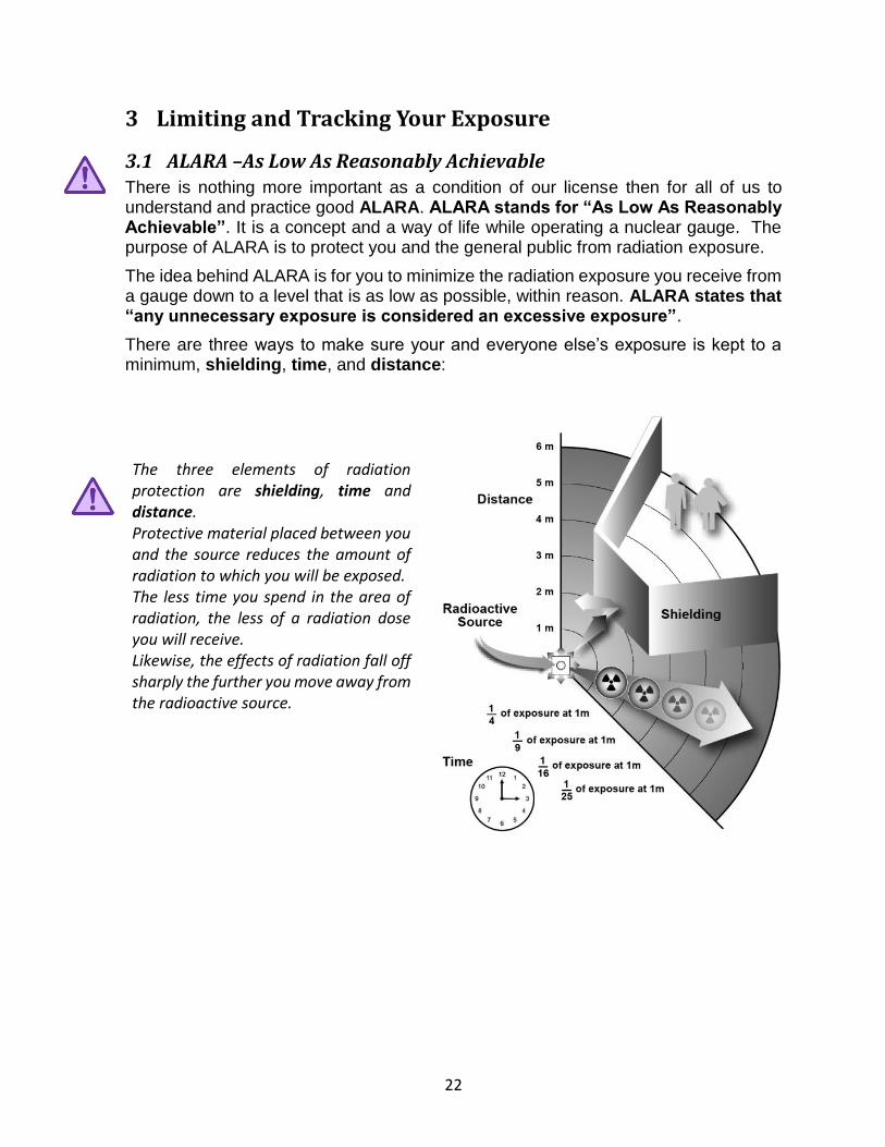
There are three ways to make sure your and everyone else’s exposure is kept to a minimum, shielding, time, and distance:
The three elements of radiation protection are shielding, time and distance. Protective material placed between you and the source reduces the amount of radiation to which you will be exposed. The less time you spend in the area of radiation, the less of a radiation dose you will receive. Likewise, the effects of radiation fall off sharply the further you move away from the radioactive source.

23
1) Shielding – Moisture density gauges are heavy, usually 30-40 lbs. One reason for all this weight is the shielding built into the gauge. The base of the gauge is made of lead, a good shield for radiation. An even better shield, tungsten, is typically used to create a bio-shield directly around the radioactive sources in the gauge. The safe position for a source rod is when the rod is fully retracted into the gauge. In the safe position the shielding will absorb most of the radiation released by the sources.
Let the shielding do its job! Always keep the source rod retracted into the safe position when the gauge is not in use. Once a test is completed, and before you record the results, retract the source rod into the safe position. If a PCC Density test is being performed, the rod must be quickly cleaned before the rod is retracted.
To give you an idea as to how effective the shielding is, consider the transport index of the gauge. The transport index of the gauge, also known as T.I., is a measurement of the radiation dose at one meter away from the gauge per hour.
Typically, a T.I. for a moisture density gauge is 0.2mrem – 0.6mrem (safe position). Let’s say your gauge has a T.I. of 0.2. That means for every hour you sit one meter away from the gauge you are absorbing 0.2mrem radiation. At that rate you could sit one meter away from the gauge for a year and never achieve your allowable 5,000mrem dose for the year.
But, if you did sit unnecessarily and intentionally next to your gauge, you would be in violation of the ALARA principle. It doesn’t matter that you are under your annual limit – it matters that this type of exposure is unnecessary and therefore excessive. 2) Time – You always want to limit your time around a gauge. When preparing the test
area keep the gauge locked in the vehicle. When taking a test push the start button and then back away from the gauge (10 feet is usually sufficient). After completing the test, lock the gauge back in the vehicle. When transporting a gauge always store the gauge in the rearmost part of the vehicle.
Your time spent near a gauge should result in exposures that can be measured in seconds, not minutes.

24
3) Distance – Distance may be the most important and effective component of ALARA. Telling you to maintain your distance whenever possible from a radioactive source is the easy way to obey the distance component of ALARA.
Explaining the reason is a little more difficult.
A law of physics called the inverse-square law explains that some physical quantity or strength is inversely proportional to the square of the distance from the source of that physical quantity. In a nutshell it means that doubling your distance from source decreases your dose by factor of four and tripling the distance decreases the dose nine-fold.
That’s because the radiation release is a constant that is being spread over an ever increasing area as you move away from it and it therefore quickly loses its intensity.
The same holds true with gauge radiation. It quickly drops off as you move away from the gauge.
The intensity at one distance is typically known and it is necessary to calculate the intensity at a second distance. Using the following formula, we can calculate the intensity of a radioactive source at a different distance than the distance it was originally measured. The equation takes the form of:
Where: I1 = Intensity of Radiation at Distance 1
I2 = Intensity of Radiation at Distance 2
D1 = Distance 1 from source
D2 = Distance 2 from source
I 1 D 1 2
D 2 2
I 2 =

25
For example: If the intensity of a radioactive source at 2’ from the source is 6mrem/hour, what is the exposure of that same source 10’ away?
Using this formula, substitute the known values and solve for I2.
24 ÷ 100 = 0.24 mrem/hr @ 10’
When you push the start button for a test you should move away as the gauge completes the test, typically one minute. Ten feet should be enough – you will want to stay close enough to move the gauge out of harm’s way (heavy construction vehicles) or to limit access to the gauge by unauthorized individuals.
By practicing effective ALARA you can ensure that your exposure will be kept to a minimum.
6 x 22
102 = I
2
6 x 4
100 = I
2
24
100 = I
2
I 1 D 1 2
D 2 2
I 2 =

26
3.2 Tracking Your Exposure – Your TLD
A TLD (Thermoluminescent Dosimeter) is a device that measures the amount of radiation that an individual absorbs over a given period of time. Having employees wear a dosimeter is the best way to track how much radiation they are exposed to while in the presence of a gauge.
TLD’s contain small crystals that are capable of storing some of the energy from radiation. When heated to a specific temperature they release the
energy in the form of light that can be measured to determine the dose. TLD’s are exchanged every 3 months.
The dosimeters, usually a clip-on device, must be assigned to workers at the beginning of each period.
Every worker must be wearing a dosimeter on any day they encounter a gauge:
• No dosimeter = no gauge use.
• Dosimeters cannot be shared.
• Dosimeters are easy to forget but don’t store them with the gauge. Radiation is always present.
• Don’t wear dosimeters to the dentist or doctor because x-rays will be recorded.
• Don’t expose dosimeters to excessive heat or sunlight.
• A front belt loop or shirt pocket is a good place to wear a dosimeter.
At the end of each quarter return your dosimeter your District Materials office.
Exposure reports show readings for the most recent quarter, year to date, and lifetime exposures for each employee. They must be kept on file permanently. Copies will be distributed to certified technicians annually.
3.3 Agencies, Licensing, Regulations and Recordkeeping The possession and use of a moisture density gauge requires a license issued by the Iowa Department of Public Health.
Conditions that were originally established in your license must be followed. Any changes to these conditions will more than likely require an amendment to the license.

27
3.4 The Specific License Moisture density gauge owners are required to have a “Specific License”. A specific license allows for the use of a device with sealed sources and places the responsibility of protecting the general public and environment in the hands of the licensee. The sealed sources must only be used in the device and for the purposes intended as described in the license.
The specific license identifies the radioactive material in its chemical and physical form, maximum activity and the purposes for which it may be used. A specific license requires the licensee to have appropriately trained and qualified personnel, appropriate facilities, equipment and procedures to ensure safe operations.
3.5 Enforcement The regulations and the conditions of your license can be enforced by the NRC, Agreement States, the U.S. DOT (including divisions such as the FAA), the EPA, law enforcement (including the FBI), fire and rescue, and other federal, state and local agencies.
3.6 Protecting the General Public, Property and Our Employees The mission of the regulatory agencies is to protect persons and property from any harmful effects of radioactive materials. That includes our employees. The agencies will conduct inspections and issue penalties to assure their mission is met. The DOT will be charged fees, including those for licensing, amendments, inspections, reciprocity and penalties, to help fund these agencies.
Another mission of the regulatory agencies is to help us run an effective and successful gauge radiation safety program.
3.7 The Radiation Safety Officer (RSO) Your license requires that senior management designate an individual as Radiation Safety Officer (RSO). This individual will establish, maintain, enforce and control the company gauge radiation safety program and act as the contact person for the regulatory agency. When the Department is contacted or inspected by the regulatory agency they will want to speak with the RSO.
Senior management is required to supply the RSO with the necessary means, including training, to carry out the position of RSO and should work with the RSO to make sure that all conditions and compliance of the license are met.
The RSO will maintain complete, accurate and organized records. The RSO is responsible for making necessary amendments and notifying the regulatory agency of these amendments. The RSO will keep the safety program updated as to any changes in the regulations.

28
4 Transportation and Storage of Gauges
4.1 A Step by Step HAZMAT Guide
Step One - Storage and Security
An important requirement of our license is to provide a safe and secure storage area for gauges that protects members of the public from excessive levels of radiation. Levels for a member of the public individual are to be <100mrem/year or <2mrem/hr.
The term “general public” refers to anyone, even DOT employees, not certified in nuclear gauge operation.
A storage location for your gauge must be secure and at least 15 feet from a full-time work station.
There must be a “Notice to Employees” poster in a public area and a “Radioactive Materials” sign on the storage door.
Security of radioactive
materials is a very important
issue and we want to do all
we can to make certain our
materials remain under our
control.
All gauges must be stored in an approved and secure storage area. There must be 4 locks between the general public and radioactive material. The term “general public” also refers to any DOT employee not certified in nuclear gauge operation.
In addition to the 4 lock requirement, gauges must also be double-locked. The
“double-lock” requirement means that there are two barriers that prevent an intruder
from reaching the gauge.
If a thief can find a way to walk away with the gauge by defeating only one lock then
you have not met the conditions of the double-lock security requirement. For example,
a gauge with its handle locked and 2 locks on the gauge case which is stored in a
locked storage room has 4 locks, but if the locked room is broken into, there is nothing
to keep a thief from just stealing the whole case and breaking the other locks at their
convenience. It is not properly double-locked. The easiest way to solve this problem
is to have the case secured to an anchor bolt or permanent structure in the room with
a locked cable. That would force the thief to defeat two locks before stealing the gauge.

29
The same rule applies when transporting a gauge. To adequately secure a gauge in the open bed of a vehicle, two locks on the gauge case and two locked chains or cables securing the gauge/case to the body of the vehicle are required.
Cased gauges should also incorporate two locks – one on the gauge case and one on the handle of the gauge.
Step Two - Before You Go - Checking the Condition of the Gauge
When removing a gauge from security, make sure that the gauge and gauge case are intact and undamaged. Make sure the sliding block shielding the bottom of the source rod (above the hole in the base of the gauge is located) is functional and fully closed.
Always sign the gauge out. Gauge owners and the RSO must always know the location of each gauge at all times. Remember, the person signing out the gauge is personally responsible for its well-being.
All gauges have had their yearly leak tests performed, have been calibrated, lubricated, and have had new batteries installed by Central Materials personnel before the beginning of each construction season.
Before you take the gauge to perform a test, make sure the gauge is operational. Are the batteries working, or in the case of Troxler gauges, are the batteries charged? Turn it on and make sure the display appears.
Check the condition of the gauge case. Are there any holes, cracks or areas where the plastic has worn away? Are the clasps in undamaged condition? If there is any damage you can’t use that case.
Does the gauge have a lock on the handle? Is there a lock on the outside hasp?
How do the labels look? Can you read all the information contained on all labels? If not, the label needs to be replaced.
Before you leave with the gauge you must remember your role in protecting yourself and the general public from any unnecessary exposure to radiation.
The concepts of ALARA; protecting yourself from radiation exposure through time, distance and shielding, are of upmost importance during the transport of the gauge.

30
You are primarily in charge of keeping the gauge out of harm’s way and for keeping unauthorized individuals away from the gauge. The gauge is most vulnerable when it is away from the storage area.
Step Three - Are You Wearing Your TLD?
Don’t leave the office without it. You can’t transport or operate a gauge if you’re not wearing your TLD. And you can’t borrow one from someone else.
TLDs should be stored in a radiation free area at the office.
Step Four - Understanding the Labels and Documents
Before you remove the gauge for transport you must first have a bill of lading and emergency response documents. Labels and documents are used to communicate the hazards associated with portable nuclear gauges. Shippers and emergency response individuals are trained to recognize this information and take the necessary precautions. Examples of these labels and documents with explanations of the information are described on the next page.
There must be two Yellow Radioactive II labels on opposite broadsides. There must also be two Air Cargo Only Labels on opposite broadsides. These labels must always be in legible condition.
The Type “A” Package label identifies the type of case you are using to store the gauge as well as identifying information in the event of emergency response. It should be placed on one broadside of the gauge case next to one of the Yellow Radioactive II Labels and be in legible condition.

31
Shipping documents must also communicate the hazards associated with portable nuclear gauges. Every time a gauge is assigned to you and you are transporting the gauge anywhere, you must have this shipping document, also called a bill of lading.
The shipping document must also be accompanied by an Emergency Procedures Sheet. The emergency procedure sheet lists the emergency actions you would take in the event of an accident or theft. It also includes the 24 hour emergency contact numbers.
When a gauge is picked up at Central Materials in Ames, these 2 documents will be provided with the gauge.
You must have direct access to these two documents whenever transporting a gauge. Direct access also means readily viewable, meaning that the documents cannot be placed in the gauge case, glove compartment or trunk. Place them in the seat beside you. Emergency response personnel know to look for HAZMAT information on the passenger seat or document holder on the driver side door. If you leave the vehicle place the documents on the driver’s seat.

32
Step Five - Preparing the Vehicle
Before you secure the gauge in a vehicle you should have all necessary restraints in place. The gauge must be secured inside the vehicle with two independent controls. A gauge must be secured, blocked and braced in a storage area of a vehicle. The gauge cannot be transported in an area of the vehicle that has passengers.
Examples of proper storage for different types of vehicles include:
a) Typical passenger automobile – The gauge must be secured in the trunk. The first independent control would be the trunk lock. The second independent control would be a locked chain or cable securing the gauge case to the body of the vehicle inside the trunk. You cannot transport a gauge in the seat beside or behind you.
b) Van, SUV or station wagon – The gauge must be secured in the rearmost part of the vehicle, behind the rearmost passenger seating. The vehicle’s door locks would act as the first level of control. An additional locked chain or cable attached to the gauge and inside body of the vehicle would act as the second. Make sure to block and brace the gauge to ensure no movement inside the vehicle. Conceal the case with a blanket or cover.
c) Pick-up truck – You must use two locked deterrents attached to the gauge case to the body of the vehicle as well as two locked deterrents that prevent anyone from opening the gauge case, such as two locked latches on the outside of the case or one locked latch along with one locked cable wrapped around and overtop the case that likewise prevents opening the case. The gauge should be blocked and braced to prevent shifting or bouncing and be concealed with a blanket or tarp.

33
Step Six - Be Nice to the Gauge
Gauges are heavy and seem very solid. Gauge cases also seem to be solidly constructed. But both will break and both are expensive.
Gauges can cost as much as a small car. There is a lot of precision and balance built into a gauge. Banging a gauge around, be it inside or outside the case, will destroy that precision and balance, resulting in repair costs that can run into the thousands of dollars. All gauges come with a drill rod that is used to create a hole for the source rod. The source rod is not a substitute for a drill rod. Hitting it with a hammer will bend or break it, which not only leads to a costly repair bill but also results in an incident that must be reported to the regulatory agency.
A gauge inside a case makes for a very heavy and awkward package. Grabbing the handle on the side of the case and dragging the package it to its destination is an easy way to save your back but also an easy way to wear a hole into the base of the cannot be used to transport a gauge. New cases can cost $400.00+. Use a cart or enlist the aid of another person to move the gauge to and from the vehicle.
Gauges are not waterproof. Do not leave them out in the rain or set them in puddles of water. Likewise, internal condensation can have the same effects as rain. The electronics in the gauge will fry if exposed to moisture. The temperature changes a gauge is exposed to can cause condensation. Take steps to “air out” the inside of the gauge. Many gauges have vent ports that can help reduce condensation.
Make sure storage areas are not subject to flooding. Place gauges on pallets or shelves.
Do not let gauges “cook” on a hot asphalt surface. When testing on asphalt never allow the gauge to sit on the surface beyond the test period. The hot temperature can overheat the electronics in the gauge and distort the readings.
Step Seven - Security while in Transport
Security concerns regarding gauges are at an all time high and therefore awareness of security risks are a training priority. Because gauges are portable they are more vulnerable to theft and damage. RSO’s must teach their employees to recognize and respond to security threats.
It is very rare that a thief is targeting the gauge itself. More often the vehicle is the target. That is why regulatory agencies frown on the idea of using the vehicle as a temporary storage area. However, if you must leave the gauge in the vehicle you need to take extra measures in securing your vehicle.
Always park the vehicle in well lit areas and, if possible, behind gated access. If you stop at rest areas and have other workers with you, take turns using the facility. If you stop at a restaurant always keep the vehicle in sight (sit at a window).
Thieves target anything they believe has value. To a thief a gauge case looks like any other tool chest or power-tool box. They’re usually in a hurry and they don’t stop to read the labels and stickers on the case. It is only later that the thief discovers he or she has a device with radioactive materials. At that point they are only interested in

34
getting rid of the gauge as fast as they can. That’s why they’re often recovered in ditches, fields and rivers.
Step Eight – Gauges at the Worksite Means Constant Surveillance
Always keep constant surveillance on the gauge while taking tests. Only remove the gauge from the vehicle when you are in the act of taking a test. When the test is finished, immediately return it and secure it in the vehicle. Do not chain it to a telephone pole or some other location that can be accessed by unauthorized individuals.
Step Nine – Temporary Storage in a Vehicle
Once the day is done and you’re on your way back make sure to keep all transport security and control requirements in place When absolutely necessary, you can use the vehicle as a temporary storage area. The gauge cannot be brought into a hotel or motel, nor can it be stored in a home, garage or local shed or storage area that is not pre-authorized. Take every means reasonably available to provide the ultimate security for a vehicle that is storing a gauge.

35
5 Emergency Procedures
5.1 In the Event of Damage at the Worksite: 1. Attend to anyone that may have been injured.
2. Determine the location of radioactive sources (typically the source rod).
3. Take control and deny access to the area (15 feet in all directions).
4. If a vehicle is involved keep it on site until it is determined that it is not contaminated.
5. Gather details about accident and damage.
6. Stay at the site but contact RSO with details.
7. If necessary, the RSO will contact the IDPH and police.
8. The RSO will give guidance on whether to move the gauge or;
9. The RSO will travel to the site with a radiation survey meter.
5.2 In the Event of Damage in a Vehicle Accident:
1. Attend to injuries.
2. Deny access.
3. Gather details, document actions and take photos.
4. Contact the RSO and/or emergency response number.
5. Wait for instructions or arrival of emergency response.
5.3 In the Event of Theft: 1. Contact the RSO.
2. Call the regulatory agency.
3. Immediately contact the police.
A Nuclear Gauge must be attended to at all times when it is in use in the field. It is very unlikely a gauge that is being watched carefully will be stolen or accidently damaged.

36
6 Gauge Operation
6.1 Standard Counts Standard counts provide a quick reference check to ensure that your gauge is operating correctly. One of the accessories you receive with a gauge is a standard block, typically a rectangular block of plastic material. Set your gauge on the block and take a standard count. It will measure the number of counts received from the density and moisture sources. The results should be very close to previous standard counts, typically 1% for density and 2% for moisture. Standard counts should be taken every day you use the gauge. Always record the results for use and comparison to future counts.
Remember! If the gauge electronics are turned off, the gauge is still emitting radiation!
The procedure for obtaining a standard count:
1. Turn the gauge on and let it warm up for 20 minutes (Be aware that some gauge models automatically turn off after approximately 10 minutes to conserve battery power).
2. Make sure the base of the gauge and the top of the standard block are clean.
3. Place the standard block on a dense, flat surface such as concrete or compacted subgrade or surfacing material (no tailgates).
4. Most standard blocks have a small metal butt plate that rises above the surface of the block. For Troxler gauges, the gauge should be placed on the block with the source rod at the opposite end of the butt plate. Humboldt gauges are just the opposite; the source rod end should be against the butt plate. Make sure to slide the gauge towards and up against the butt plate.
5. The source rod stays in the safe position when taking the test.
6. Make sure there are no other gauges within 30 feet.
7. Make sure to take the test in an area away from any large vertical objects including walls, vehicles and people.
8. Take one automatic 4-minute standard count per manufacturer instructions. This count should be within 1% of the latest standard count established for the gauge. In the event the standard count varies by more than 1%, make a note of that number, reject that count on the gauge and then obtain another standard count. The two standard count numbers just obtained should be within 1% of each other and within 2% of the latest established standard count. If so, retain and record the last standard count taken.

37
6.2 Moisture Content and Density of Soils (IM 334)
Buildings and roads are only as good as the foundations they are built upon. Hills have to be flattened and valleys have to be filled. Ideally, you can use the material removed from the hill to fill in the valley. But you must use heavy rolling equipment to compact the soil to create a safe and sturdy foundation for the building or road. And to effectively compact the soil you typically put it down in 4 – 12 inch lifts. Compaction efforts differ depending on the types of soils you are compacting. For example, sandy soils can be easier to compact than clay soils.
The one big advantage you have in determining how well you are compacting the soil is the use of the moisture density gauge. Density measurements have proven to be an excellent indicator of the soils ability to support loads. Density is the mass per unit volume. Wet density, also known as bulk density, typically consists of the soils and moisture evident in the ground that you are compacting. Dry density consists of only the soil solids and is typical of a lab analysis. You will need to correlate the field measurement to the lab measurement and this is best done by subtracting the gauge’s moisture measurement reading from the gauge’s wet density reading:
Dry density = (Wet density – moisture)
The gauge will automatically make this calculation for you.
The key to maximum density is the percentage of moisture in a given soil. The moisture acts as a bond for the soil. If it is too wet, the water will displace the denser soil particles, no bonding will occur, and you end up with mud. If it’s too dry there will be increased friction and you will not achieve the desired bonding. The gauge will help you determine the desired optimum moisture content. The other key factor, pressure applied by the compaction rollers, will allow you to match up to the design criteria.
When taking a test, the gauge measures the amount of radiation detected over a predetermined timeframe, usually one minute. The detector tubes count the radiation that is able to pass through the material between the bottom of the source rod and the detector tubes. The denser the material, the lower the amount of radiation that is able to reach the detector tubes to be counted. The gauge converts these counts into a wet density reading. It is referred to as wet density because the material under the gauge has natural moisture contained in its physical form.
The other radioactive source, Americium 241, embedded in the base of the gauge, measures moisture at the same time the gauge is measuring wet density. The gauge software then automatically adjusts the readings.

38
When working with a gauge on soil it is wise to follow a few guidelines:
a) When testing on soils always prepare the ground by using the scraper plate to smooth out any obstacles or fill in any voids. This will reduce the chance that open pockets or protruding objects could impact your reading.
b) When using the drill rod always make sure to first place your drill rod removal device – this is something you will probably only forget once!
39
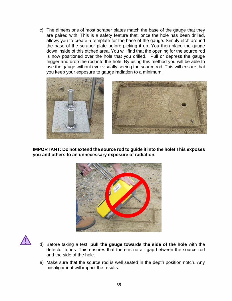
c) The dimensions of most scraper plates match the base of the gauge that they are paired with. This is a safety feature that, once the hole has been drilled, allows you to create a template for the base of the gauge. Simply etch around the base of the scraper plate before picking it up. You then place the gauge down inside of this etched area. You will find that the opening for the source rod is now positioned over the hole that you drilled. Pull or depress the gauge trigger and drop the rod into the hole. By using this method you will be able to use the gauge without ever visually seeing the source rod. This will ensure that you keep your exposure to gauge radiation to a minimum.
IMPORTANT: Do not extend the source rod to guide it into the hole! This exposes you and others to an unnecessary exposure of radiation.
d) Before taking a test, pull the gauge towards the side of the hole with the detector tubes. This ensures that there is no air gap between the source rod and the side of the hole.
e) Make sure that the source rod is well seated in the depth position notch. Any misalignment will impact the results.

40
f) Always practice good ALARA by returning the source to its safe position before recording your results.
g) Always practice good ALARA by maintaining your distance during the test.
h) Always practice good security by never taking your eyes off the gauge while in operation. This will prevent possible damage from heavy equipment.
i) Never take a test while within 30 feet of another gauge.
j) Never take a test adjacent to large vertical objects, including vehicles and people.
k) After use, always return the gauge to its case and secure the case to the vehicle.
6.3 Asphalt Moisture and Density of Cold-in-Place Recycling (IM 504)
Preparation of the test site is the same as for earthwork except the surface is not scraped.
6.4 PCC Density (IM 358)
The consolidation of concrete is an important factor in its durability. The result obtained from the nuclear gauge is compared to a corrected rodded density test result. The corrected nuclear density must be greater than 98% of the corrected rodded density result. (Standard Specification 2413.03.E.2.g)
When taking PCC density readings, the moisture content readings are of no consequence.
The source rod is lowered into plastic PCC, typically on a bridge deck, and the gauge
measures the amount of radiation detected over a predetermined timeframe, usually one minute. The detector tubes count the radiation that is able to pass through the material between the bottom of the source rod and the detector tubes. The denser the material, the lower the amount of radiation that is able to reach the detector tubes to be counted. The gauge converts these counts into a wet density reading. It is referred to as wet density because the material under the gauge has natural moisture contained in its physical form.
Report this data on Form 821297, Nuclear Test Report-Density of Plastic P.C. Concrete. This blank form can be found on the Iowa DOT Web Page, Materials Section at: www.dot.state.ia.us/materials/index.htm and clicking “Forms”.

41
6.5 Some Possible Reasons for Errors in Gauges There may be nothing more frustrating than a gauge that isn’t measuring correctly and there can be plenty of reasons for malfunctioning gauges:
a. Environmental factors – Environmental errors are typically out of the control of the operator.
1. Natural hydrogen content – Some soils contain naturally bound hydrogen. The gauge views this natural bound hydrogen as moisture. The natural hydrogen may give a false low dry density reading, which in turn can lead to false low percent compaction. The Proctor procedure may likewise be fooled by the hydrogen. An additional oven dry or microwave test will be needed to recalculate the values. They can be time consuming but necessary.
2. Bad luck of the draw – Sometimes, a spot is specified, through random selection, where a test must be performed. If a “soft” spot is selected it can give a bad representation of the overall job. But, then again, some believe that the job is only as good as its weakest spot.
3. Trench & vertical object errors & corrections – Sometimes you’re put in a spot where there is no escape from adjacent vertical walls or objects. These surfaces can reflect back the neutron radiation and give a higher moisture count than actual. You can correct for trench factors by performing a standard count on a normal surface setting and compare to a trench standard count. The difference should be subtracted from the actual trench moisture count.
4. Operator errors – All gauges have small degrees of errors evident in their systems. You can never achieve a perfect level of precision and accuracy because of the very slight mechanical imperfections and electronic drift. But the last thing you need is additional errors due to operator oversights. Don’t compromise your readings due to these errors:
• Make sure the source rod is well seated in the depth notch.
• Make sure, once the source rod is extended into the hole, that you pull the gauge and inserted rod against the backside of the hole. This will eliminate any open air space between the rod and soil.
• Make sure the base of the gauge is sitting flush against the ground surface. Use the scraper plate to properly smooth the ground, removing any protruding objects and filling any air voids.
• Make sure to run your standard counts every day you use the gauge.
42
6.6 Gauge Maintenance Basics As in the case with most high quality test equipment, moisture density gauges will provide many years of dependable service provided proper maintenance is performed on a periodic basis.
1. The bottom plate of the gauge and the cavity formed by the scraper ring should be cleaned frequently. If the gauge is used in wet sand or concrete, the cavity should be cleaned every day. If you regularly use the gauge in soils clean the cavity when raising and lowering the source rod.
2. DO NOT apply grease or any lubricant to nuclear gauge source rod. If the source rod becomes hard to extend or retract, contact your Radiation Safety Officer. Applying grease to source rod will increase the chance of getting small particles into the trigger mechanism.
3. Do not leave nuclear gauge carrying case open to the elements. Moisture can condense inside the nuclear gauge causing damage to the electronics.
4. Keep the nuclear gauge carrying case clean. Just like moisture, small particles of dust can get into the nuclear gauge, which could result in problems with the trigger mechanism and electronics.
5. DO NOT open any part of the nuclear gauge without the permission of the Radiation Safety Officer.
6. Humboldt gauges receive new alkaline batteries at the beginning of every construction season, so there should be no need to replace them. Troxler gauges use NiCad batteries that will develop a short battery life if the gauge gets recharged too often and without being fully discharged. Charge the batteries only when necessary! It would also be a good habit to write in the log book every time batteries get recharged. If you observe a gauge requiring frequent recharging, contact your RSO to get fresh batteries installed.
7. An important component of a gauge that requires maintenance is the bottom plate and sliding block located in the bottom plate of the gauge. Typical problems reported as a result of insufficient maintenance include: difficulty in raising and lowering the source rod, improper sliding block operation, and erratic moisture or density counts. Central Materials personnel perform yearly maintenance, if you notice problems with the sliding block, contact your RSO.
The typical portable nuclear gauge license does not allow you to perform extensive service and repair to your gauges. Just because you are proficient at electronics or mechanical assembly and you are able to obtain parts, you are expressly forbidden to disassemble a gauge, specifically the source rod. You have to obtain a special license to do so. The additional license carries many extra regulations and requirements.

43
7 Glossary
Absorbed dose: The quantity of ionizing radiation deposited into a material, including an organ or tissue, expressed in the terms of the energy absorbed per unit mass of material. The basic unit of absorbed dose is the rad or its SI equivalent, the gray (Gy).
Activity (Radioactivity): The rate of decay of a radionuclide, more formally, the number of decays per time. Its SI unit is the Becquerel (Bq) corresponding to one radioactive decay (disintegration) per second; its old unit, the curie (Ci), was originally defined as the activity of 1 gram of radium-226 or 3.7 x 10/10 disintegrations per second.
Acute dose: An acute dose means a person received a radiation dose over a short period of time. Example: 5,000mrem per hour.
Acute effect: Effects in organisms manifest themselves soon after exposure to radiation and are characterized by inflammation, edema, denudation and depletion of tissue, and hemorrhage.
Acute radiation exposure: A radiation exposure that occurs over a relatively short period of time (less than 24 hours).
Acute Radiation Syndrome-“ARS” (Radiation Sickness): A person exposed to radiation will develop ARS only if the radiation dose was very high, penetrating (gamma rays), encompassing the whole body and received in a short period of time.
Agreement State: States that assumed authority under Section 274b of the Atomic Energy Act to license and regulate by-product materials (radioisotopes), source materials (uranium and thorium), and certain quantities of special nuclear materials.
Air Cargo Only label: Two labels are required on opposite sides of the gauge case and next to the Yellow ll labels that instruct that gauges can only be shipped on cargo aircraft – no passenger aircraft.
ALARA: “As Low As Reasonably Achievable” – Taking every reasonable safeguard to protect person and public against ionizing radiation exposure.
Alpha particle: A heavy particle emitted form the nucleus of an atom. It consists of two protons and two neutrons, which is identical to the nucleus of a helium atom without electrons. These heavy charged particles lose their energy very quickly in matter. They are easily shielded by clothing, a sheet of paper or the top layer of skin. Alpha particles are only hazardous when ingested. Alpha particles emitted by the radioactive materials in the gauge are permanently shielded and therefore not used in the operation of the gauge.
Americium-241 (Am241): Portable nuclear gauges use a radioactive isotope of Americium, Am241, coupled with beryllium to produce neutron radiation for measuring hydrogen/moisture content.
Atom: The smallest particle of an element that can enter into a chemical reaction.
Atomic Mass: The weight of an atom measured in atomic mass units, typically protons and neutrons.

44
Atomic Number: The number of protons in the nucleus of an atom and the number of electrons in a neutral atom. This number determines the atom’s chemical element.
Atomic Weight: The mass of an atom. Mass is roughly determined by counting the number of protons and neutrons in the nucleus.
Background Radiation: Ionizing radiation that occurs naturally in the environment, including cosmic, terrestrial and radon radiation; also known as natural background radiation.
Becquerel (Bq): An SI unit of measure for activity. One becquerel equals 1 disintegration per second. Typically, becquerels associated with portable gauges, are expressed in billions (GBq) of a becquerel. There are 37,000,000,000 becquerels in 1 curie.
Beta particle: A high speed particle emitted from the nucleus which is identical to an electron. They can have a -1 (electron) or +1 (positron) charge and are effectively shielded by thin layers of metal or plastic. Beta particles are most hazardous when ingested. Beta particles emitted from the radioactive materials in the gauge are permanently shielded and therefore not used in the operation of the gauge.
Bill of Lading: A shipping document required whenever radioactive material is transported or shipped on public highways, waterways, cargo aircraft or rail. It must be readily visible and accessible to the driver.
Certificate of Competent Authority/IAEA Certificate/Special Form Certificate: A certificate that confirms the manufacture and encapsulation of radioactive material into an impervious container. See: Sealed Source.
Cesium 137 (Cs137): Radioactive isotope of Cesium which decays by beta emission into barium 137m, which in turn emits a photon for measuring density. Cs137 has a half-life of 30.17 years.
Chronic exposure: Exposure to a source of radiation over a longer period of time, typically greater than 24 hours.
Contamination (radioactive): Contamination means that radioactive materials are released in the form of solids, gases or liquids into the environment and contaminate people externally, internally or both.
Controlled area/zone: An area where entries, activities and exits are controlled to help ensure radiation protection and prevent the spread of contamination.
Cosmic Radiation: Radiation produced in outer space that enters the earth’s atmosphere.
Count: Electronic pulse from a radiation detector tube that indicates an ionizing event. Portable nuclear gauges use Geiger-Muller tubes to detect ionizing events.
CFR: Code of Federal Regulations
Chronic dose: A chronic dose means a person received a radiation dose over a long period of time. Example: 300mrem per year.

45
Chronic Radiation Exposures: Radiation exposures that occur over extended periods of time (greater than 24 hours). Exposure to natural background is a chronic radiation exposure.
Contamination: Radioactive material distributed and in contact with some person, equipment or area. Requires decontamination efforts.
Critical Mass: The minimum amount of fissile material necessary to achieve a self-sustaining nuclear chain reaction. Nuclear gauges only contain non-fissile material and are therefore not capable of creating a chain reaction.
Curie (Ci): The basic measure of radioactivity equal to an average transformation of 37 billion disintegrations per second. One curie is the approximate activity of 1 gram of radium. Named for Marie and Pierre Curie, founders of radium in 1898.
Decay (Radioactive): The decrease of radioactive material, specifically the emission of alpha and beta particles and gamma electromagnetic energy, with the passage of time.
Decontamination (Radioactive): The reduction or removal of radioactive contamination from a structure, object or person.
Detector (Radiation): A device that is sensitive to radiation and can produce a response signal suitable for measurement or analysis. A radiation survey meter.
Dirty bomb: A radiological dispersal device (RDD). A device designed to spread radioactive material by conventional explosives for malevolent purposes. The objective of such a device would be to cause social disruption and panic.
Dose/Dose Rate: The quantity of ionizing radiation deposited into a material, including an organ or tissue, expressed in the terms of the energy absorbed per unit mass of material. The basic unit of absorbed dose is the rad or its SI equivalent, the gray (Gy). The radiation dose delivered per unit of time.
Dose equivalent: A quantity used in radiation protection to place all radiation on a common scale for calculating tissue damage. Dose equivalent is the absorbed dose in grays multiplied by the quality factor. The quality factor accounts for differences in radiation effects caused by different types of ionizing radiation. The sievert is the unit used to measure dose equivalent.
Dosimeter: A small portable instrument such as a film badge or TLD for measuring and recording the total accumulated dose of ionizing radiation person receives.
Effective dose: A dosimetric quantity useful for comparing the overall health affects or irradiation of the whole body. It takes into account the absorbed doses received by various organs and tissues and weighs them according to present knowledge of the sensitivity of each organ to radiation. It also accounts for the type of radiation and the potential for each type to inflict biological damage. The unit of effective dose is the sievert.
Electromagnetic Radiation: A traveling wave motion that results from changing electric and magnetic fields. Types of electromagnetic waves include short-wave such as x-rays & gamma to ultraviolet, visible & infrared to longer wave such as radar and

46
radio. The gamma ray photons used in a gauge to measure density is a type of electromagnetic radiation.
Electron: Sub-atomic negatively charged particle with very low mass that orbits the nucleus.
Element: All isotopes of an atom that contain the same number of protons.
Emergency Response Sheet: A document that discusses the precautions and emergency actions pertaining to radioactive gauge during transport. An Emergency Response Sheet must be readily visible and available to the driver during transport. Similar to a Material Data Safety Sheet (MSDS).
Encapsulation/Encapsulated: The shielding that encompasses a radioactive material used in a gauge.
Exposure (Radiation): A measure of ionization in air caused by x-rays or gamma rays only. The unit of measure most often used is the roentgen.
Exposure rate: A measure of the ionization produced in air by x-rays or gamma rays per unit of time, frequently expressed in roentgens per hour.
External exposure/irradiation: An exposure received from a source of ionizing radiation outside of the body. Similar to a chest x-ray in that following exposure the individual is not radioactive. Exposure to gamma radiation from the gauge is an external exposure.
Film badge: Dosimetry monitoring device that uses photographic film to measure a person’s radiation dose.
Fissile material: Any material in which neutrons cause a fission reaction.
Fission: The splitting of a nucleus into at least two fragments, accompanied by the release of neutrons and energy. Fission of a nucleus may be initiated by absorption of a neutron or, in some materials, can happen spontaneously.
Fusion: The joining together of two or more less stable nuclei into one more stable nucleus.
Gamma ray photon radiation: High-energy electromagnetic radiation emitted from the nucleus of an atom. Gamma rays have no charge, are very penetrating and are best shielded by lead or steel. Gamma rays can cause internal and external damage. All gamma rays emitted from a given isotope have the same energy, a characteristic that enables scientists to identify which gamma emitters are present in a sample. Gamma rays penetrate tissue farther than do beta or alpha particles but leave a lower concentration of ions in their path to potentially cause cell damage. Very similar to x-rays except that x-rays originate from the outer shell of the atom. The gauge uses gamma ray photons to help measure density.
Geiger-Mueller Detector Tube: A gas filled tube that measures voltage pulses created by ionizing gamma radiation. Used in a gauge to determine density.
Geiger counter: A device that utilizes Geiger-Mueller tubes for detecting and measuring ionizing radiation. Gauges use GM tubes to help measure density.
47
Genetic effects: Effects from radiation exposure that are seen in the offspring of the individual.
Gray (Gy): This SI unit is used to measure a quantity called absorbed dose. This relates to the amount of energy actually absorbed in some material and is used for any type of radiation and any material. It does not describe the biological effects of the different radiations. One gray is equivalent to 100 rads.
Half-life: The time during which one-half of a given quantity of a radionuclide undergoes radioactive decay into another nuclear form. A half-life can last from millionths of a second to billions of years.
HAZ-MAT Training: Hazardous Materials training required for all individuals preparing or transporting gauges. Initial training is covered in the Gauge Safety Certification class and must be renewed every year.
Helium-3 Detector Tube: A helium-3 gas filled tube used to measure thermalized neutrons. Used in a gauge to determine moisture content.
IAEA: International Atomic Energy Agency.
IAEA Certificate/Certificate of Competent Authority/Special Form Certificate: A certificate that confirms the manufacture and encapsulation of radioactive material into an impervious container. See: Sealed Source.
Irradiation: Exposure to radiation.
Ingestion: Swallowing radionuclides by eating or drinking.
Inhalation: Breathing in radionuclides.
Internal exposure: An exposure received from a source of ionizing radiation inside of the body.
Inverse Square Law: The relationship that states that electromagnetic radiation intensity is inversely proportional to the square of the distance from a point source. In other words, roughly speaking, as you double your distance from a radioactive source your exposure is reduced to ¼.
Ion: A charged atom or particle. An atom that has fewer or more electrons than protons. Nuclear radiation can cause ionization.
Ionization: A process in which an atom loses or gains one or more electrons thereby forming an ion.
Ionizing radiation: Radiation that is sufficiently energetic to ionize the matter (remove electrons from the atoms thereby producing ions) through which it moves. Alpha, beta, gamma and neutron are all forms of ionizing radiation.
Irradiation: Exposure to radiation.
Isotope: A variation of a element with the same number of protons, but different number of neutrons.
Leak Test/Wipe Test: A required test for all gauges to ensure that radioactive contaminants are not escaping the special form encapsulation.

48
Lethal dose (50/30): The dose of radiation expected to cause death within 30 days to 50% so exposed without medical treatment. The generally accepted level for a lethal dose is 400rem over a short period of time.
Millirem (mrem): One one-thousandth (1/1000) of a REM.
Molecule: A combination of two or more atoms that are chemically bonded. A molecule is the smallest unit of a compound that can exist by itself and retain all of its chemical properties.
Natural background radiation: Radiation that exists naturally in the environment. It includes cosmic and solar radiation, radiation radioactive materials present in rocks and soil, and radioactivity that is inhaled or ingested.
Neutron: Neutral sub-atomic particle located in the nucleus of an atom/element.
Non-Agreement State: A state under the direct rules and regulations of the NRC.
Nondestructive testing: Testing that does not destroy the object under examination.
Non-ionizing radiation: Having lower energy and longer wavelengths than ionizing radiation it is not strong enough to affect the structure of atoms, but it is strong enough to heat tissue and cause harmful biological effects. Examples are radio waves, microwaves, visible light and infrared.
Notice to Employees Poster: A required information poster that must be available/posted for all employees of a company using gauges. This poster can be obtained from the licensing agency.
NRC: Nuclear Regulatory Commission. Federal licensing and regulatory body that oversees the use of radioactive materials in the United States.
Nuclear energy: The heat energy produced by the process of nuclear fission within a nuclear reactor or by radioactive decay.
Nuclear reactor: A device in which a controlled, self-sustaining nuclear chain reaction can be maintained with the use of cooling to remove generated heat.
Nucleus: The central part of an atom that contains the neutrons and protons. The nucleus is the heaviest part of the atom.
Occupational exposure: Radiation exposure obtained during work around a gauge.
Penetrating radiation: Radiation that can penetrate the skin and reach internal organs and tissues. Photons (x-rays & gamma rays) and neutrons are penetrating radiations. Alpha and beta particles are not considered penetrating radiation.
Photon: A discrete packet of pure electromagnetic energy that, when interacting at the molecular or atomic level, acts more like a particle rather than an energy wave. Photons have no mass and travel at the speed of light. Gamma rays and x-rays are photons.
Placards/Placarding: Radioactive lll labels that must be used displayed on the outside of a vehicle for higher quantity devices. Moisture density gauges are Radioactive ll and

49
therefore do not require placarding. DO NOT PLACARD A VEHICLE that is transporting a moisture density gauge.
Proton: A small positively charged particle found in the nucleus. The number of protons in a given atom determines the chemical identity of the element.
Quality Factor (QF): A numerical factor describing the average effectiveness of a particular type or energy of radiation in producing biological effects on humans. The multiplier assigned to a given type of radiation. Multiply the QF times rad to determine rem. A factor that converts the absorbed dose (rad) to biological damage/dose equivalent (rems).
Rad (radiation absorbed dose): A basic unit of absorbed dose that measures the energy absorbed by the body. It does not describe the biological effects of different radiations. One rad equals the dose delivered to an object of 100 ergs of energy per gram of material. It is being replaced by the gray (Gy), which is equivalent to 100 rad.
Radiation: Energy in transit in the form of high speed particles and electromagnetic waves. Electromagnetic waves, including visible light, radio, television, ultra violet (UV) and microwaves, are all types of radiation that do not cause ionizations of atoms because they do not carry enough energy to separate molecules or remove electrons form atoms. These are all forms of non-ionizing radiation. Ionizing radiation is a very high energy form of electromagnetic radiation that has enough energy to remove tightly bound electrons from their orbits around atoms. Alpha, beta, gamma ray and neutron radiation are all ionizing radiation.
Radiation dose: The quantity of radiation energy deposited into an object or medium, divided by the mass of the object or medium. The radiation dose is ionizing radiation. Ionizing radiation doses can be expressed as an absorbed dose, equivalent dose, or effective dose. The basic unit of absorbed dose is the rad or its SI equivalent, the gray (Gy).
Radiation exposure: The act of being exposed to radiation. Also referred to as irradiation. Formally in radiation detection and measurement, radiation exposure is related to the ability of photons to ionize air.
Radiation sickness: See Acute Radiation Syndrome (ARS).
Radiation source: Radioactive material packaged to use the radiation it emits.
Radiation warning symbol: A universally recognized magenta or black trefoil on a yellow background that must be displayed where radioactive materials are present or where certain doses of radiation could be received.
Radioactive: Elements that are unstable and transform spontaneously (decay) through the emission of ionizing radiation, a process known as radioactive decay.
Radioactive contamination: Radioactive material distributed and in contact with some person, equipment or area. Requires decontamination efforts.
Radioactive decay: The spontaneous disintegration of the nucleus of an atom.
Radioactive material: Any material that contains radioactive atoms.

50
Radioactivity: Process of spontaneous transformation/breakdown of the nucleus, generally with the emission of alpha or beta particles, usually accompanied by gamma rays. This process is described as decay of the atom.
Radiography: The use of radiation to create images of a subject, especially the internal features of a subject. An example of medical radiography is a dental x-ray. Industrial radiography includes x-rays of pipes and reinforced concrete construction.
Radioisotope: Isotopes of an element that have an unstable nucleus.
Radiological: Related to radioactive materials or radiation. The radiological sciences focus on the measurement and effects of radiation.
Radiological dispersal device (RDD): Also known as a dirty bomb. A device to spread radioactive material for malevolent purposes. The objective of such a device would be to cause social disruption and panic.
Radionuclide: An atom with an unstable nucleus which undergoes radioactive decay. A radioactive nuclide.
Radium: A naturally occurring radioactive material (NORM) formed by the decay of uranium and thorium. It occurs at low levels in virtually all rock, soil, water, plants and animals. Radon is a decay product of radium.
Radon: A naturally occurring radioactive gas found in rock, soil and water throughout the United States. Radon is the largest source of exposure to people from naturally occurring radiation.
Regulations: The rules and requirements of a license. All license holders must maintain, review and update a copy of the regulations from their regulatory agency.
REM (Roentgen equivalent, man): The special unit of dose equivalent. Not all radiation has the same biological effect, even for the same amount of absorbed dose. The dose equivalent in rem is equal to the absorbed dose in rad multiplied by the quality factor that accounts for the biological effect of the radiation. (1 rem = 0.01 sievert). This relates the absorbed dose in human tissue to the effective biological damage of the radiation. To determine the equivalent dose (in rem) you multiply the absorbed dose (rad) times the quality factor (QF).
RQ – Reportable Quantity: An EPA designation that establishes thresholds for quantities of radioactive materials used in gauges. An RQ designation must appear on the Type A Package Label and shipping papers for gauges that contain Am241 in excess of 10mCi. All moisture density gauges exceed this limit and must therefore show the designation.
Roentgen: A unit of measure to exposure to gamma and x-rays. It is that amount of gamma or x-rays required to produce ions carrying 1 electrostatic unit of electrical charge in 1 cubic centimeter of dry air under standard conditions. Named for Wilhelm Roentgen, discoverer of x-rays in 1895.
Safety: Prevention of damage, human error and other inadvertent acts that result in accidental radiation exposure.

51
Sealed source: A radioactive source, sealed in an impervious container that has sufficient mechanical strength to prevent contact with and dispersion of the radioactive material under the conditions of use and wear for which it was designed. May be classified “Special Form” on shipping papers and packages.
Security: Prevention of theft, sabotage and other malevolent acts involving radiation sources.
Shielding: Any effective material between a radiation source and a potentially exposed person that reduces exposure.
SI: International System of Units, also known as the metric system.
Sievert (Sv): The sievert is a SI unit used to derive a quantity called dose equivalent or equivalent dose. This relates the absorbed dose in human tissue to the effective biological damage of the radiation. Not all radiation has the same biological effect, even for the same amount of absorbed dose. To determine equivalent dose (Sv), you multiply absorbed dose (Gy) by a quality factor (QF) that is unique to the type of incident radiation. One sievert (sv) is equivalent to 100rem.
Special Form Certificate: A certificate that confirms the manufacture and encapsulation of radioactive material into an impervious container. See: Sealed Source.
Special form radioactive material: Defined in 10 CFR Part 71 as radioactive material that exists as a single solid piece or is encapsulated material that meets certain other requirements.
Stable nucleus: The nucleus of an atom in which forces among its particles are balanced.
Stochastic effect: An effect regardless of dose that assumes there is always some small probability of adverse effects. The effect increases with dose. Cancer is a stochastic effect.
Survey meter: A device used to detect and measure the presence of ionizing radiation.
TEDE - Total Effective Dose Equivalent: The sum of effective dose equivalent from external radiation and the committed effective dose inhaled and ingested radioactive material. Quoted in units of rem.
Terrestrial radiation: Radiation emitted by naturally occurring radioactive materials in the earth. Examples: Uranium, thorium & radon.
TLD: Thermoluminescent Dosimeter. Personnel dosimetry used to measure radiation dose.
Total Body Radiation Syndrome: The response of an organism to acute total body radiation exposure to all organs constituting the organism.
Total Effective Dose Equivalent (TEDE): See TEDE
Type A Package: The approved case that the gauge must be stored and shipped in.
Type A Package Label: A label that indicates the type of case used to store and ship the gauge.

52
Unstable nucleus: A nucleus that contains an uneven number of protons and neutrons and seeks to reach equilibrium between them through radioactive decay. Example: The nucleus of a radioactive atom.
Whole Body Count: The measure and analysis of the radiation being emitted from a person’s entire body, detected by a counter external to the body.
Whole Body Exposure: An exposure of the body to radiation, in which the entire body, rather than an isolated part, is irradiated by an external source.
X-ray: Electromagnetic radiation emitted from the outer shell of the atom. Is best shielded by lead or steel. Can cause external or internal hazards.
Yellow ll Radioactive Label: The radioactive label designated for gauges, two of which must adorn opposite sides of the gauge case. The label must display the hazard class(7), contents(Cs137 & Am241), activity in becquerels & millicuries, and Transport Index (TI).

P
RO
CE
DU
RE
S
M
AN
UA
L


NUCLEAR MOISTURE-DENSITY GAUGE OPERATIONAL AND SAFETY PROCEDURES MANUAL
OFFICE OF CONSTRUCTION AND MATERIALS January 2018

Page 1 of 15
SCOPE
This manual describes the operational safety procedures to be followed when using Nuclear Moisture–Density Gauges under the control of the Iowa Department of Transportation. This manual must be used in conjunction with the appropriate IMs in effect regarding testing when using a Nuclear Moisture–Density Gauge.
Page 2 of 15
TABLE OF CONTENTS
I. FIRM LOCATION…………………………………………………………………………………………………...3 a. Address………………………………………………………………………………………………….... 3 b. Contacts…………………………………………………………………………………………………… 3
II. GAUGE DESCRIPTION…………………………………………………………………………………………… 4 a. Troxler Surface Moisture-Density Gauges………………………………………………… 4 b. Humboldt Nuclear Moisture-Density Gauges…………………………………………… 4
III. STORAGE FACILITIES……………………………………………………………………………………………. 5 a. Permanent Location………………………………………………………………………………….5 b. Temporary Locations……………………………………………………………………………. 5-6 c. Storage in Vehicle……………………………………………………………………………………. 6
IV. FIRE PROTECTION………………………………………………………………………………………………… 7 V. OPERATOR'S QUALIFICATIONS ............................................................................... 7
VI. EXPOSURE MONITORING PROCEDURES................................................................. 8 VII. OPERATING AND EMERGENCY PROCEDURES...................................................... 8-9
a. Operating Procedures .................................................................................. 8 b. Emergency Procedures.............................................................................. 8-9
VIII. INVENTORY INFORMATION ………………………………..………………………………..……..……… 9 a. Utilization Log Book ..................................................................................... 9 b. Documents Provided with each Gauge........................................................ 9
IX. INVENTORY CONTROL.............................................................................................. 9 X. SERVICE .................................................................................................................. 10
XI. LEAK TESTS .............................................................................................................10 XII. DISPOSAL ............................................................................................................... 10
XIII. EMERGENCY RESPONSE INFORMATION……………….……………………………………………. 11 Appendix A Iowa Department of Public Health Materials License……………………….. 12-14 Appendix B Material Safety Data Sheet Exemption……………………………………….………….. 15

Page 3 of 15
OPERATIONAL AND SAFETY PROECEDURES TO BE FOLLOWED WHEN USING NUCLEAR MOISTURE-DENSITY GAUGE
I. FIRM LOCATION A. Address
Iowa Department of Transportation Office of Construction and Materials 800 Lincoln Way Ames, IA 50010
B. Contacts
Kevin Jones Materials Testing Engineer Office of Construction and Materials Iowa Department of Transportation 800 Lincoln Way Ames, IA 50010 515-239-1237 Rodney Graven Radiation Safety Officer Office of Construction and Materials Iowa Department of Transportation 800 Lincoln Way Ames, IA 50010 515-233-7743 515-370-2166 Stephen Upchurch Electronic Engineering Technician Office of Construction and Materials Iowa Department of Transportation 800 Lincoln Way Ames, IA 50010 515-239-1502

Page 4 of 15
II. GAUGE DESCRIPTIONS
A. Two (2) Troxler Surface Moisture-Density Gauges, Model No. 3440
Radiological Specifications
Gamma Source: 8 mCi ±10% Cesium-137
Neutron Source: 40 mCi ±10% Americium-241: Beryllium
Source Housing: Stainless steel encapsulation
Shielding: Tungsten, lead and cadmium
Surface Dose Rates: 20.5 mrem/hr max., neutron and gamma
Source Rod Material: Stainless steel
Shipping Case: DOT 7A, Type A
Source Seal Approval, Domestic and International Shipment: Special Form B. Seven (7) Humboldt Moisture-Density Gauges, Model No. 5001
Radiological Specifications
Gamma Source: 10 mCi ±10% Cesium-137
Neutron Source: 40 mCi ±10% Americium-241: Beryllium
Source Housing: Stainless steel encapsulation
Shielding: Tungsten, lead and cadmium
Surface Dose Rates: 17.3 mrem/hr max., neutron and gamma
Source Rod Material: Stainless steel
Shipping Case: DOT 7A, Type A
Source Seal Approval, Domestic and International Shipment: Special Form C. One (1) Instrotek/CPN Moisture-Density Gauge, Model MC-3 Elite
Radiological Specifications
Gamma Source: 10 mCi ±10% Cesium-137
Neutron Source: 50 mCi ±10% Americium-241: Beryllium
Source Housing: Stainless steel encapsulation
Shielding: Tungsten, lead and cadmium
Surface Dose Rates: 16.0 mrem/hr max., neutron and gamma
Source Rod Material: Stainless steel
Shipping Case: DOT 7A, Type A
Source Seal Approval, Domestic and International Shipment: Special Form

Page 5 of 15
III. STORAGE FACILITIES
A. Permanent Location – Materials Laboratory - Ames
1. The building is rigidly constructed, with adequate fire safety equipment.
2. The gauges are stored in a separate room. The area is kept locked and secured at all times with s available only to licensed operators. In addition, the gauge’s source rod is kept locked when not in use.
3. The room is posted with appropriate radiation warning signs.
4. The building is locked and secured during non-working hours.
5. The facility meets with the approval of the Radiation Safety Officer.
6. The name and phone number of the Radiation Safety Officer and his designated alternate who can be contacted in case of emergency are posted.
7. The facility shall always be subject to inspection for compliance to these requirements.
B. Temporary Locations
1. The building shall be rigidly constructed, with adequate fire safety equipment.
2. The gauge(s) will be stored in a separate room. The area will be kept locked and secured at all times with keys available only to licensed operators. In addition, the gauge’s source rod is kept locked when not in use.
3. The room will be posted with appropriate radiation warning signs.
4. The building will be locked and secured during non-working hours. If available, security guards will make rounds to check on above.
5. The facility will be inspected by and meet the approval of the Radiation Safety Officer.
6. The building superintendent will be given the name, address and phone number of the Radiation Safety Officer and his designated alternate who can be contacted in case of emergency.
7. The facility shall always be subject to inspection for compliance to these requirements.
8. Temporary locations may include:
District One - Resident Construction Offices
1308 Iowa Avenue West 512 West Clark Marshalltown, IA 50158 Jefferson, IA 50129
District Two - Materials
428 43rd Street SW Mason City, IA 50401
District Two - Resident Construction Offices
2224 225th Street New Hampton, IA 50659

Page 6 of 15
District Three - Materials
4621 US 75 North Sioux City, IA 51108
District Three - Resident Construction Office
1833 Industrial Road North Cherokee, IA 51012
District Four - Materials
2310 East 7th Street Atlantic, IA 50022
District Four - Resident Construction Offices
3538 S. Expressway 701 East Taylor Council Bluffs, IA 51501 Creston, IA 50801
District Five - Materials
301 West Briggs Fairfield, IA 52556
District Five - Resident Construction Offices
US 34 West 205 East Taft Street Chariton, IA 50049 Mount Pleasant, IA 52641
District Six - Materials
5455 Kirkwood Blvd. Cedar Rapids, IA 52404
District Six - Resident Construction Offices
1009 West Main Street 8721 NW Blvd. 14117 IA RTE 136 North Manchester, IA 52057 Davenport, IA 52809 Dyersville, IA 52040
C. Storage in Vehicle
1. If the gauge is going to be stored overnight in vehicle the following conditions must be met:
a. Prior approval by the Radiation Safety Officer will be necessary.
b. Vehicle must be locked with the gauge adequately secured. In an open bed vehicle, the gauge shall be secured inside the cab of the vehicle.
c. Vehicle must be kept at same location as where certified operator is staying. In addition, the vehicle must be parked in a well-lighted area for security reasons.
d. At no time shall the gauge be taken inside a private residence or a motel room overnight.
e. If an accident occurs with vehicle follow conditions under Emergency Procedures.

Page 7 of 15
IV. FIRE PROTECTION A. Building is of non-combustible construction.
B. The walls are concrete block construction.
C. The ceiling and floors are reinforced concrete.
D. Fire extinguishers are mounted on nearby walls.
E. Building conforms to existing State regulations and Codes.
Note: An engineering evaluation of the likelihood of source retention in the source housing following a severe accident involving fire was conducted. The results of the testing showed: (1) No loss of the shielding integrity of the device at temperatures below 250 ͦC (482 Fͦ). Although a 250 Cͦ temperature would not, based on the ANSI classification of the source capsule, result in leakage of radioactive material, such a temperature would melt the epoxy used to “cold weld” the source cup into the source rod. At this temperature, there would be no loss of shielding around the Cs-137 capsule. The capsule would remain within the source rod, being held there by the threads. At temperatures over 327 Cͦ (621 ͦF), the lead surrounding of the Americium-241:Beryllium source capsule would melt. Though this would result in a loss of shielding to some degree, it is below the temperature rating for the source capsule. The results of the prototype testing and engineering analysis support the assignment of an ANSI standard rating of ANSI-54-164-154-R1.
V. OPERATOR’S QUALIFICATIONS A. To become a certified operator, the individual must have satisfactorily completed the DOT’s course given by the Radiation Safety Officer. The operators will be trained on the following topics:
1. Nature of sources.
2. Operation of equipment.
3. Safety procedures for normal operation.
4. Emergency procedures.
5. Packaging and shipping of gauges.
6. Radiation exposure factors.
7. Occupational dose limits.
8. Radiation monitoring.
9. Film badge usage.
10. Reporting malfunction or problems.
11. Emergency procedures.
B. Certified individuals must be a full-time employee, over the age of 19, of the Iowa Department of Transportation to be certified to operate gauges licensed under the Iowa Department of Transportation by the Iowa Department of Public Health. Any female, known to be pregnant, is prohibited from operating a gauge.
C. The Radiation Safety Officer will issue a certificate of training upon successful completion of the course to operators.

Page 8 of 15
VI. EXPOSURE MONITORING PROCEDURES
A. Each certified operator who operates a gauge at any time during a yearly quarter is provided with a monitoring TLD (Thermo Luminescent Dosimeter) badge which is to be submitted to Troxler Radiation Monitoring Services, Research Triangle Park, North Carolina for analysis of gamma and neutron dosage.
B. A record of exposure information is maintained and monitored by the Radiation Safety Officer.
C. Any unusually high dosages (more than 20 mrem per quarter) will be investigated by the Radiation Safety Officer.
VII. OPERATING AND EMERGENCY PROCEDURES A. Operating Procedures.
1. Operator(s) are required to wear a film badge when using or transporting gauge.
2. Keep the source rod in the “safe” or stored position when not in use (this includes from one test location to another).
3. While exposure dose levels are well within limits for radiation workers, never expose yourself to the bare source without sufficient justification for the additional dose.
4. Keep all unauthorized persons out of operating area. Suggested distance is 15 ft.
5. Maintain security of the instrument at all times. The source lock shall be in place any time the gauge is not in use.
6. The gauge shall be kept in carrying case (shipping case – DOT 7A, Type A, Yellow II Label, 0.1 Transport Index) with the source rod locked while in transit. It must be transported only by a certified operator in an approved vehicle.
7. While being transported in a vehicle, the gauge shall be located in an area as far away from any person(s) as possible (trunk of sedan, back of station wagon/SUV or back of a pickup bed).
8. The vehicle transporting the gauge must be kept locked when unoccupied.
9. If an accident occurs with vehicle while transporting gauge, follow conditions under Emergency Procedures.
B. Emergency Procedures
In the event of damage at the work site:
1. Attend to anyone that may have been injured.
2. Determine the location of radioactive sources (typically the source rod).
3. Take control and deny access to the area (15 feet in all directions).
4. If a vehicle is involved keep it on site until it is determined that it is not contaminated.
5. Gather details about accident and damage – if possible, perform radiation survey.
6. Stay at the site but contact RSO with details.

Page 9 of 15
7. If necessary, the RSO will contact the IDPH and police.
8. The RSO will give guidance on whether to move the gauge or;
9. The RSO will travel to the site with a radiation survey meter.
In the event of damage in an auto accident:
1. Attend to injuries.
2. Deny access.
3. Gather details, document actions and take photos.
4. Contact the RSO and/or emergency response number.
5. Wait for instructions or arrival of emergency response.
In the event of theft:
1. Contact the RSO.
2. Call the regulatory agency.
3. Immediately contact the police.
At the earliest practical moment, the U.S. Department of Transportation’s National Response Center will be notified at 800-424-8802, of an accident that occurs during the course of transportation (including loading, unloading and temporary storage) in which fire, breakage, spillage or suspected contamination occurs involving shipment of radioactive materials, in accordance with 49 CFR 171.15.
VIII. INVENTORY INFORMATION A. Utilization Log Book – information recorded is as follows:
1. Model and serial number
2. Date gauge is removed from and returned to storage.
3. Name of operator or transporter.
4. Destination.
B. Documents provided with each gauge:
1. Nuclear Moisture-Density Gauge Safety Procedures Manual.
2. Copy of license issued by the Iowa Department of Public Health with amendments. (Included with the Safety Procedures Manual)
3. Gauge operator’s manual.
4. Most recent gauge calibration sheets.
IX. INVENTORY CONTROL A. A record is kept by Radiation Safety Officer showing where gauges are located at all times. B. Every 6 months, a thorough inventory is done to check gauges for usage and condition. C. Every 12 months, an audit is performed. Summaries of exposure reports, leaks tests and training are
included along with radiation survey results from the Nuclear Vault area.

Page 10 of 15
X. SERVICE A. All service to gauges will be done by Stephen Upchurch, Electronic Engineering Technician in the
Office of Construction and Materials. As stated in the DOT’s Radioactive Materials License (0066-1-85-PG), source rod removal can only be performed by Stephen Upchurch.
B. At no time will any service be done by the operator.
XI. LEAK TESTS A. The leak test is administered and monitored by the Radiation Safety Officer on a yearly basis.
B. The testing is done using an approved kit supplied by Humboldt Scientific, Troxler Electronics Laboratories or any company licensed to provide the service.
C. A test paper supplied with the kit shall be wetted with isopropyl alcohol prior to wiping the two radioactive sources in the gauge. The test paper is then placed in plastic envelopes on which the following information is recorded:
1. Company name.
2. Address.
3. Gauge Model.
4. Gauge Serial Number.
5. Source Serial Numbers.
6. Date of test.
D. The plastic envelope is placed in a shipping envelope along with leak test analysis form which also contains the above information which is then shipped to Humboldt Scientific, Troxler Electronic Laboratories, Inc. or to any company which is licensed to provide such services, for analysis.
XII. DISPOSAL A. Any gauge which is no longer of use to the Iowa Department of Transportation will be returned to a
current nuclear gauge manufacturer for disposal.

Page 11 of 15
XII. EMERGENCY RESPONSE INFORMATION
Emergency Response Numbers: 515-233-7743 or 515-370-2166 Rodney Graven, RSO 515-239-1237 Kevin Jones, Testing Engineer 800-535-5053 Humboldt 24 Hour Emergency Response Number 919-549-9539 Troxler 24 Hour Emergency Response Number 800-535-5053 InstroTek 24 Hour Emergency Response Number 515-281-3478 or 515-323-4360 (after normal working hours) Iowa Department of Public Health
POTENTIAL HAZARDS
IMMEDIATE HAZARDS TO HEALTH
• External radiation hazard from unshielded radioactive material. • Low-level radioactive material; little personal radiation hazard when shielded. • Materials in special form are not expected to cause contamination in accidents. • Some radioactive materials cannot be detected by commonly available instruments. • Potential internal radiation hazard from inhalation, ingestion, or breaks in skin, only if special form capsule is
breached.
FIRE OR EXPLOSION
• No risk of fire or explosion. • Radioactivity does not change flammability or other properties of the materials.
EMERGENCY PROCEDURES
IMMEDIATE PRECAUTIONS
• Isolate hazard area to within a 10-15 foot radius of the device and restrict access. • Emergency response actions may be performed prior to any measurement of radiation; limit entry to shortest
time possible. • Notify local authorities and Radiation Control Authority of accident conditions. • Detain uninjured persons; isolate equipment with suspected contamination and delay cleanup until receiving
instruction from Radiation Control Authority.
FIRE
• Do not move damaged containers; move undamaged containers out of fire zone. • Small Fires: Dry chemical, CO2, water spray, or regular foam. • Large Fires: Water spray, fog (flooding amounts).
SPILL OR LEAK
• Do not touch damaged containers or exposed contents. • Damage to outer container may not affect primary inner container. • Special form capsules are not expected to leak as a result of an accident or fire.
FIRST AID
• Use first aid treatment according to the nature of the injury. • Advise medical personnel that victim may be contaminated with low-level radioactive material. • Except for the injured, detain persons exposed to radioactive material until arrival or instruction of Radiation
Control Authority.

Page 12 of 15

Page 13 of 15

Page 14 of 15
Page 15 of 15
MATERIAL SAFETY DATA SHEET EXEMPTION
Material Safety Data Sheets (MSDS) are not required for our gauges.
Radioactive materials are exempt from coverage under the OSHA’s Hazard Communication Standard (HCS) if the only hazard they pose is radiological. Since the only hazard posed by the radioactive sealed sources in nuclear gauges is radiological (they do not present any other physical or chemical hazards) they are exempt from the HCS. This means that Materials Safety Data Sheets are not required.
Excerpts from the OSHA regulations which exempt the radioactive sealed sources from MSDS requirements are shown below:
29 CFR 1910.1200, Section(b) “Scope and application.”
(b)(1)
This section requires chemical manufacturers or importers to classify the hazards of chemicals
which they produce or import, and all employers to provide information to their employees about
the hazardous chemicals to which they are exposed, by means of a hazard communication
program, labels and other forms of warning, safety data sheets, and information and training. In
addition, this section requires distributors to transmit the required information to employers.
(Employers who do not produce or import chemicals need only focus on those parts of this rule
that deal with establishing a workplace program and communicating information to their
workers.)
1910.1200(b)(6)
This section does not apply to:
(b)(6)(xi)
Ionizing and nonionizing radiation;

INS
TR
UC
TIO
NA
L
ME
MO
RA
ND
UM
S


October 16, 2012 Matls. IM 206
Supersedes October 20, 2009
1
Office of Construction & Materials
NUCLEAR TEST EQUIPMENT
GENERAL
The Office of Materials supplies test equipment containing radioactive isotopes for the purpose of
determining the density and moisture content of soils, the density of HMA, and the density of PC
Concrete. Properly used, this equipment poses no serious threat to the health and safety of
personnel. However, because of the nature of the energy source, certain precautions must be
observed.
The conditions in the Nuclear Materials License, issued to the Iowa Department of Transportation
control how its employees use, store, and transport nuclear testing equipment. The Office of
Materials Training Course is based on the regulations set forth in its license and applies only to full
time employees of the Iowa Department of Transportation. Intermittent and summer employees
will not be certified nor will they be allowed to operate or transport a nuclear gauge. This training
course DOES NOT qualify workers to use, store or transport nuclear gauges that are regulated
under other nuclear materials license, such as city, county, contractors, and consulting firms.
A. Training
1. Personnel operating or transporting this equipment must have successfully completed a
training course conducted by the Central Laboratory or a nuclear gauge manufacturer, in
the principles of nuclear testing and safety practices.
2. A Certified Nuclear Gauge Operator Card and Certification will be issued to each
employee who satisfactorily completes the training course. This certification shall be valid
for one year from the date of initial issuance. A 90-day grace period will be allowed.
3. Re-certification will be issued upon satisfactory completion of a Re-certification Training
Course.
4. Certification will be withdrawn from employees that abuse the nuclear gauge, abuse the
use of the Thermo Luminescent Dosimeters (TLDs) or violate the safety rules outlined in
this memorandum.
5. A current list of Certified Nuclear Gauge Operators will be issued to each District Materials
Office after the training courses are completed.
B. Radiological Safety
1. All conditions in our Nuclear Materials License must be followed.
2. Employees under the age of 19 shall not be permitted to operate, or assist in the operation
of nuclear gauges.
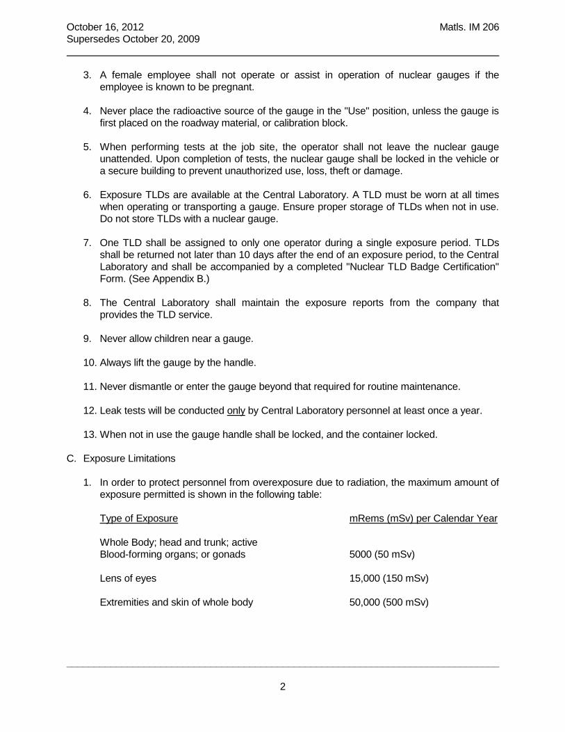
October 16, 2012 Matls. IM 206
Supersedes October 20, 2009
______________________________________________________________________________
2
3. A female employee shall not operate or assist in operation of nuclear gauges if the
employee is known to be pregnant.
4. Never place the radioactive source of the gauge in the "Use" position, unless the gauge is
first placed on the roadway material, or calibration block.
5. When performing tests at the job site, the operator shall not leave the nuclear gauge
unattended. Upon completion of tests, the nuclear gauge shall be locked in the vehicle or
a secure building to prevent unauthorized use, loss, theft or damage.
6. Exposure TLDs are available at the Central Laboratory. A TLD must be worn at all times
when operating or transporting a gauge. Ensure proper storage of TLDs when not in use.
Do not store TLDs with a nuclear gauge.
7. One TLD shall be assigned to only one operator during a single exposure period. TLDs
shall be returned not later than 10 days after the end of an exposure period, to the Central
Laboratory and shall be accompanied by a completed "Nuclear TLD Badge Certification"
Form. (See Appendix B.)
8. The Central Laboratory shall maintain the exposure reports from the company that
provides the TLD service.
9. Never allow children near a gauge.
10. Always lift the gauge by the handle.
11. Never dismantle or enter the gauge beyond that required for routine maintenance.
12. Leak tests will be conducted only by Central Laboratory personnel at least once a year.
13. When not in use the gauge handle shall be locked, and the container locked.
C. Exposure Limitations
1. In order to protect personnel from overexposure due to radiation, the maximum amount of
exposure permitted is shown in the following table:
Type of Exposure mRems (mSv) per Calendar Year
Whole Body; head and trunk; active
Blood-forming organs; or gonads 5000 (50 mSv)
Lens of eyes 15,000 (150 mSv)
Extremities and skin of whole body 50,000 (500 mSv)

October 16, 2012 Matls. IM 206
Supersedes October 20, 2009
______________________________________________________________________________
3
Because of the sensitivity of radiation to an unborn child, the exposure limit for an
expectant mother is 500 mRem (5 mSv) for the entire pregnancy.
D. Transportation of Gauges
1. The individual responsible for physically transporting the nuclear gauge must provide
secure measures to adequately prevent the unauthorized removal of the gauge from its
place of storage during transport. When the gauge is in a vehicle and not under your
constant control and surveillance, it must be secured as follows:
A. In a car, van, pick-up with a topper, or a pick-up cab – The transportation case
must be secured to a bracket with the cables provided. The vehicle, gauge, transportation
case, and the cable around the case must also be locked.
B. In a pick-up bed – The transportation case must be secured with two separate
cables to two separate brackets on the pick-up bed with the cables provided. The gauge,
transportation case, and the cable around the case must also be locked.
2. A shipping document must accompany the gauge during transit. This document identifies
the radioactive material and its container. The shipping documents are manufacturer-
specific. For example, a Troxler document must be used to transport a Troxler gauge and
cannot be used to transport a Humboldt gauge. (See Appendix D.)
3. While the nuclear gauge is being transported the shipping document shall be within the
driver's reach. Unattended vehicles containing gauges shall have the shipping document
in view on the vehicle's seat.
4. For an overnight stay at a motel, hotel or other lodging place, the locked gauge must be
left in the locked vehicle. In the case of pickup trucks, the gauge must be locked in the cab
of the truck.
E. Storage of Gauges
1. When the gauge is not in field use, the normal storage will be at a Resident
Construction Office or District Office. This should be a special area designated for this
purpose; with a radiation caution sign posted to notify personnel of the existence of
radiation. There should be four locks between the general public and the radioactive
material (the lock on the gauge handle is considered one). In addition, the gauge must
be “double locked”. The double lock requirement means that there are two barriers that
prevent an intruder from reaching the gauge. An example of double locked would be a
lock on the room that houses the gauge and a cable securing the gauge case to an
anchor on the wall or floor.
F. Accidents and Incidents
1. If a gauge is lost or stolen, notify the Radiation Safety Officer at the Central Laboratory
IMMEDIATELY. If a gauge is involved in an accident follow the established Emergency

October 16, 2012 Matls. IM 206
Supersedes October 20, 2009
______________________________________________________________________________
4
Procedures. (See Appendix E.)

April 20, 2004 Matls. IM 206
Supersedes October 21, 2003 Appendix B
1
IOWA DEPARTMENT OF TRANSPORTATION OFFICE OF MATERIALS
NUCLEAR TLD BADGE CERTIFICATION
I HEREBY CERTIFY THE FOLLOWING:
1. The operator(s) has attended the training course in nuclear testing conducted by the Central
Laboratory.
2. All safety practices outlined in Materials IM 206 have been followed.
3. The following individual(s) was wearing a nuclear exposure badge on his front waist, while
operating nuclear testing equipment, and that the exposure as determined on the enclosed
badges should be indicative of radiation received for the appropriate time period.
EXPOSURE PERIOD/DATE: From: ____________________ To:
APPROX.
NAME TLD BADGE NO. GAUGE NO. HRS. USED
__________________________ _________________ _____________
__________________________ _________________ _____________
__________________________ _________________ _____________
__________________________ _________________ _____________
__________________________ _________________ _____________
__________________________ _________________ _____________
COMMENTS:
The above information, to the best of my knowledge, is complete and accurate.
Engineer in Charge Date
cc: Office of Materials Laboratory
District File
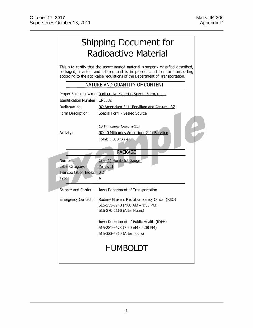
October 17, 2017 Matls. IM 206 Supersedes October 18, 2011 Appendix D
1
HUMBOLDT
515-281-3478 (7:30 AM - 4:30 PM)
515-323-4360 (After hours)
515-233-7743 (7:00 AM – 3:30 PM)
Iowa Department of Public Health (IDPH)
515-370-2166 (After Hours)
Emergency Contact: Rodney Graven, Radiation Safety Officer (RSO)
Shipper and Carrier: Iowa Department of Transportation
Transportation Index: 0.2
Type: A
Number: One (1) Humboldt Gauge
Label Category: Yellow II
PACKAGE
Activity: RQ 40 Millicuries Americium-241; Beryllium
Total: 0.050 Curies
Form Description: Special Form - Sealed Source
10 Millicuries Cesium-137
Identification Number: UN3332
Radionuclide: RQ Americium-241: Beryllium and Cesium-137
Shipping Document for
Radioactive Material
Proper Shipping Name: Radioactive Material, Special Form, n.o.s.
This is to certify that the above-named material is properly classified, described, packaged, marked and labeled and is in proper condition for transporting according to the applicable regulations of the Department of Transportation.
NATURE AND QUANTITY OF CONTENT

October 17, 2017 Matls. IM 206 Supersedes October 18, 2011 Appendix E
1
EMERGENCY PROCEDURES
8. The RSO will give guidance on whether to move the gauge or;
Emergency Phone Numbers
4. If a vehicle is involved keep it on site until it is determined that it is not contaminated.
5. Gather details about accident and damage – if possible, perform radiation survey.
6. Stay at the site but contact RSO with details
7. If necessary, the RSO will contact the IDPH and police.
Rodney Graven Radiation Safety Officer (RSO)
515-233-7743 (Daytime hours) 515-370-2166 (Mobile)
5. Wait for instructions or arrival of emergency response.
In the event of theft:
1. Contact the RSO.
2. Call the regulatory agency
3. Immediately contact the police
At the earliest practical moment, the U.S. Department of Transportation’s National Response Center will be notified at 800-424-8802 of an accident that occurs during the course of transportation (including loading, unloading and temporary storage) in which fire, breakage, spillage or suspected contamination occurs involving shipment of radioactive materials, in accordance with 49 CFR 171.15.
9. The RSO will travel to the site with a radiation survey meter.
In the event of damage in an auto accident:
1. Attend to injuries.
2. Deny access.
In the event of damage at the work site: 1. Attend to anyone that may have been injured.
2. Determine the location of radioactive sources (typically the source rod).
Nuclear gauges present no major health dangers if basic precautions are taken and common sense is used. By following proper procedures and principles of radiation protection, and by helping others do likewise, you can feel comfortable and assured that your workplace is save.
3. Gather details, document actions and take photos.
4. Contact the RSO and/or emergency response number.
3. Take control and deny access to the area (15 feet in all directions).
Iowa Department of Public Health Bureau of Radiological Health
515-281-3478 (Daytime hours) 515-323-4360 (After hours)
A nuclear gauge must be attended to at all times when it is in use in the field. It is very unlikely that a gauge being attended to will be accidently damaged.


October 20, 2015 Matls. IM 334 Supersedes April 15, 2015
1
Office of Construction & Materials
DETERMINING MOISTURE CONTENT & DENSITY OF SOILS, BASES & SUBBASES WITH A NUCLEAR GAUGE
SCOPE This test method describes the procedure used in determining the in-place density and moisture content of soils, cold-in-place recycled asphalt pavement, soil aggregate sub-base, soil lime sub-base, and cement treated granular base or sub-base by the use of nuclear method. OPERATOR QUALIFICATION In addition to complying with IM 206 (as applicable), an operator, to determine the moisture content and density of soils, bases, and sub-bases with a nuclear gauge, must first demonstrate knowledge and proficiency in various related areas that may affect the test result. The specific areas will be determined by and demonstrated to the satisfaction of the District Materials Engineer or an authorized representative. PROCEDURE A. Apparatus
1. A recognized nuclear moisture-density gauge containing a radioisotope, detectors and
related circuitry. The gauge shall be capable of determining densities by either the backscatter or direct transmission methods.
2. A reference standard for the purpose of taking standard counts, and for checking
equipment operation. 3. A drill rod and combination guide-scraper plate for preparing the testing site.
4. Manufacturer Instructional Manual.
B. Standard Counts
1. Place the reference standard in a position recommended by the manufacturer to obtain standard counts.
2. Allow the gauge to warm up as suggested by the manufacturer.
3. Take one automatic four-minute standard count per manufacturer instructions. This count should be within 1% of the latest standard count established for the gauge. In the event the standard count varies by more than 1%, make a note of that number, reject that count on the gauge and then obtain another standard count. The two standard count numbers just obtained should be within 1% of each other and within 2% of the latest established standard count. If so, retain and record the last standard count taken.
4. If the day-to-day shift in the standard count varies more than 2% for moisture or 1% for
density, reset the gauge on the standard and repeat the procedure in B3. 5. Keep a log of the gauge standard counts.

October 20, 2015 Matls. IM 334 Supersedes April 15, 2015
2
6. Standard counts should be taken twice a day to detect any shift during daily use. C. Site Preparation
1. Select a random location in the testing area. Test will be run at three locations at this station, the center and the ¼ points from each side of the center. Moisture and density determinations will be based on the average of the readings from the three locations. Test locations should be such that the gauge will be a least 6 in. away from any vertical projection. Be sure the vehicle is at least 10 ft. away from the test site.
2. Remove all loose and disturbed material, and remove additional material as necessary to
reach the top of the compacted lift to be tested. 3. Prepare a horizontal area, sufficient in size to accommodate the gauge, using the scraper
plate supplied with the gauge; by planing to a smooth condition so as to obtain maximum contact between the gauge and material being tested. Make sure the gauge sits solidly on the site without rocking.
4. The maximum depressions beneath the gauge shall not exceed 1/8 in. Use native fines or
fine sand to fill voids and level the excess with the scraper plate. The total area thus filled with native fines or sand should not exceed ten percent of the bottom area of the gauge.
D. Moisture Determination
1. Prepare test site as described in C. 2. Obtain a one-minute moisture count. 3. The moisture measurement is based upon the thermalization of fast neutrons by hydrogen
atoms. Because some materials may contain hydrogen other than free water or may contain thermalizing elements other than hydrogen, the moisture content value should be verified by comparison with Materials IM 335. If the moisture differential between the two tests is greater than 1.5%, then not less than four moisture samples should be oven dried to determine the moisture correction factor. Refer to gauge manufacturer instructions for correcting gauge-derived moisture content values. Typically, if the gauge reading is higher than the values obtained by oven dry samples, the error is due to hydrogen containing materials. If the gauge reading is lower than that obtained by oven drying, the error is likely due to materials which absorb thermalized neutrons. Note: Moisture correction is not typically required for embankment materials.
E. Density Determination - Direct Transmission
1. Place the guide plate on the site for the moisture determination and drive the drive pin
through the guide to a depth at least 2 in. below the depth of material to be measured. Remove the drive pin by pulling straight up in order to avoid disturbing the access hole.
2. Place the gauge over the access hole and push the index handle down until the source has
reached the desired depth. 3. With the source at the desired depth, pull the gauge so that the probe is in contact with the

October 20, 2015 Matls. IM 334 Supersedes April 15, 2015
3
near side of the hole, take and record a one-minute wet density count. 4. Generally no corrections for density need be made due to soil compositional error,
however, if a soil has a mean atomic weight higher than limestone, the gauge may indicate a high density. If it is felt that the gauge is indicating an unrealistic high density, two undisturbed soil cores shall be obtained. These two cores should be sent to the Central Materials Laboratory and be tested for density using Iowa Test Method 102. A correction factor should be obtained based on the density measured by the Central Materials Laboratory. This factor should be applied to the field nuclear densities.
F. Calculations
When determining the moisture correction described in D4, refer to gauge manufacturer’s instructions for moisture correction calculations.
G. General Notes
1. Do not attempt to operate a nuclear gauge before thoroughly reading the Instruction Manual.
2. Do not attempt to operate a nuclear gauge before thoroughly reviewing the radiological
safety precautions described in Office of Materials IM 206, "Nuclear Test Equipment."

April 18, 2017 Matls. IM 358 Supersedes October 20, 2015
1
Office of Construction & Materials
DETERMINING PLASTIC DENSITY OF PORTLAND CEMENT CONCRETE WITH A NUCLEAR GAUGE
SCOPE The plastic density of PC Concrete is dependent on the materials, proportions, air content and consolidation. For given materials and proportions, the consolidation of the concrete is an important factor in its durability. This test procedure determines the percent rodded density by comparing the in-place density from the nuclear gauge to the corrected rodded density determined using Materials IM 340.
PRECAUTIONS
• Before operating a nuclear gauge, you must have attended a course on operation and safety at the Central Laboratory and have a current Qualified Nuclear Gauge Operator Card.
• Never touch the end of the source rod with your hand. A plastic glove and a rag should be used when cleaning the rod and the rod should be pointed away from the body during this operation.
• DO NOT use any lubricants (i.e. spray lubricants or oil) on the source rod. Central Materials personnel will perform the necessary lubrication.
PROCEDURE A. Determination of the Corrected Standard Rodded Density Materials IM 340 is used to determine the density of the concrete mix. Use the tamping rod, not a vibrator, to consolidate the concrete. Perform at least 1 test per each ½ day of concrete production. Determine the following: Vm, Volume of measuring bowl in cubic feet (on the side of the bowl). W1, Weight of the measuring bowl plus concrete in pounds. W2, Weight of the measuring bowl only in pounds. W3 = W1-W2, Weight of Concrete in pounds.
m
3
V
W Density Rodded
Content AirDetermined - 100
94.0Density x Rodded Density Rodded Corrected

April 18, 2017 Matls. IM 358 Supersedes October 20, 2015
2
Example: Determined Rodded Density = 142.4 pcf Determined Air Content = 7.4%
7.4 - 100
94.0 x 142.4 Density Rodded Corrected
92.6
94.0 x 142.4
= 144.6 pcf B. Test Record Forms 1. Record the following data in a field book or worksheets: a. Date b. Calibrated volume of the measuring bowl, Vm c. Weight of measuring bowl, W2. d. Weight of measuring bowl full of concrete, W1 e. Location where concrete sample was obtained f. Corrected rodded density C. Determination of the "In-Place" Density of the Plastic PC Concrete
1. Apparatus Nuclear gauge including standard calibration block and gauge instruction manual.
2. Standard Counts
a. Place the standard calibration block in a position recommended by the manufacturer to obtain standard counts.
b. Allow the gauge to warm up as suggested by the manufacturer. c. Take one automatic 4-minute standard count per manufacturer instructions. This
count should be within 1% of the latest standard count established for the gauge. In the event the standard count varies by more than 1%, make a note of that number, reject that count on the gauge and then obtain another standard count. The two standard count numbers just obtained should be within 1% of each other and within 2% of the latest established standard count. If so, retain and record the last standard count taken
d. If the day-to-day shift in the standard count varies more than 2% for moisture or 1%
for density, reset the gauge on the standard calibration block and repeat the procedure in 2c above.

April 18, 2017 Matls. IM 358 Supersedes October 20, 2015
3
e. Keep a log of the gauge standard counts. f. Standard counts should be taken twice a day to detect any shift during daily use.
3. Test Procedure a. Prior to concrete placement, determine locations to avoid being near steel and
select areas where a total minimum depth of 3 in. is available. Mark reference points for locations where nuclear densities are to be obtained.
b. Immediately behind the finishing machine, but prior to texturing and curing
operations, center the nuclear gauge on the plastic concrete surface over the test location center.
c. Lower the source rod to the 2 in. direct transmission indent, making sure the gauge
is properly seated. Do not go past the 2 inch depth with the source rod. The void created could cause the density reading to be lower.
d. Pull the gauge slightly toward the scalar end. e. Obtain a 1-minute density count. f. Without retracting the source rod, put on a plastic glove and pick the gauge up and
clean the end of the source rod and the bottom of the gauge with a rag to remove all paste. Retract the source rod into the gauge.
g. Record the "in-place" nuclear density value (N2) from the gauge.
4. Calculations Corrected Nuclear Density = N2+ C N2, "in-place" nuclear density in pounds per cubic foot. C, Correction Factor (an adjustment factor for some gauges)
Density Rodded Corrected
100Density x Nuclear Corrected Density Rodded of %
D. Test Record Forms 1. The following additional data will be recorded in field book or worksheets a. Location of "in-place" nuclear density b. “In-place" density, N2 c. Corrected nuclear density d. % of rodded density 2. Report this data on Form #821297. This blank form can be found at: W:\Highway\Materials\Nuclear gauge forms

April 18, 2017 Matls. IM 358 Supersedes October 20, 2015
4
Figure 1. Measuring Bowl Showing Volume of Container (in Cubic Feet)
Figure 2. Nuclear Gauge in Place on Standard Calibration Block

April 18, 2017 Matls. IM 358 Supersedes October 20, 2015
5


October 20, 2015 Matls. IM 504
Supersedes October 21, 2014
Office of Construction & Materials
COLD-IN-PLACE RECYCLING of HOT MIX ASPHALT (HMA) PAVEMENT
GENERAL
Cold in-place recycling (CIR) is a method of rehabilitating the existing asphalt pavement
surface. As an “in-place” technology, all work takes place on the roadway using the existing
asphalt pavement. Generally, material is not wasted or removed. The existing asphalt surface
material is cold milled to the specified depth, sized to the specified gradation (maximum particle
size), mixed with the specified asphalt stabilizing agents, and placed back on the pavement to
the specified width, depth, profile, and cross-slope. This is accomplished in a continuous single-
pass operation with the appropriate equipment. The CIR layer is compacted to the required
density with rubber-tired and steel-wheeled rollers and can be opened to traffic the same day in
most cases. As part of the project, the CIR layer is covered with a new HMA surface course or
thin asphalt surface treatment.
This rehabilitation process is normally applied to projects with a structurally adequate pavement
section. Projects with insufficient subgrade support should not be candidates for this type of
rehabilitation. Projects with higher traffic volumes should do an engineering analysis to
determine if this rehabilitation strategy can be successfully applied.
MATERIAL SAMPLING FOR MIX DESIGN
STABILIZING AGENT
The stabilizing agent from the proposed supplier is required for the mix design. A 10-gallon
sample is needed to prepare the replicates for the range of application rates.
EXISTING PAVEMENT
Samples for mix design testing should be obtained from at least 3 locations. Significant mixture
differences in the pavement to be recycled may require separate samples. Samples for mix
design obtained from the milled RAP are the most representative. Mill a minimum of 50 feet of
project length at each sample location. All samples shall represent the entire depth of CIR
processing. 150 lb. bulk sample is needed to develop the mix design.
DEVELOPING THE MIX DESIGN
STANDARD EMULSION
A mix design is not required for CIR with standard emulsion. The production starts at 0.3
gallons of emulsion per square yard per inch of CIR compacted thickness. The Engineer may
adjust the asphalt stabilizing agent application rate in the field to improve stability or minimize
cracking.
FOAMED ASPHALT
The mix design of CIR with foamed asphalt requires a laboratory capable of generating
controlled quantities of foamed asphalt. The mix design determines the proper application rate
of foamed asphalt to achieve stability under dry and saturated conditions. Indirect tensile
testing is used to measure the CIR mixture strength.
The mix design with foamed asphalt is performed by the Iowa DOT Central Asphalt Lab. The
current mix design procedure is described in appendix A.

October 20, 2015 Matls. IM 504
Supersedes October 21, 2014
2
ENGINEERED EMULSION
The mix design of CIR with engineered emulsion requires close coordination with the emulsion
supplier to formulate the residual asphalt binder to satisfy the mix design criteria. The mix
design determines the emulsion properties and the application rate for the emulsion that satisfy
the mix design criteria. A series of tests are used to measure strength and low temperature
flexibility.
Procedures for the mix design with engineered emulsion are described in appendix B.
FIELD CONTROL OF ASPHALT STABILIZING AGENT
CALIBRATE AND MONITOR STABILIZING AGENT RATE OF FLOW
The contactor shall provide a positive means of accurately metering the rate of flow and total
delivery of the asphalt stabilizing agent. The Engineer should verify the rate of application with
production yield checks during construction.
The contractor may use the delivery pump as one of the options to determine total gallons of
stabilizing agent used on the project. Pump accuracy is determined by comparing a metered
volume or weight, correcting for temperature, against a known volume or weight. The pump
must consistently deliver with in ± 1.5% of the required gallons (liters). If the contractor elects
to use delivery ticket quantities and production yield, calibration of the pump would not be
necessary.
The production yield is determined by comparing the quantity of asphalt stabilizing agent used
to the quantity required for the square yards per inch (square meters per centimeter) of
compacted thickness as measured. Production yield shall be with in the specified tolerance of
the target application rate. The application rate specifies the quantity of standard emulsion,
foamed asphalt, or engineered emulsion added to the RAP volume. Use Form #CIR-1, Yield
Check to verify the rate of application by yield check.
If the standard emulsion is diluted, the target application rate must be adjusted by the amount
of emulsion dilution. Dilution is not normally performed for CIR applications because it adds
excess water to the CIR mixture.
ADJUSTMENT OF STABILIZING AGENT CONTENT
The Engineer must approve any revision in the asphalt stabilizing agent content. Changes in
the content, particularly a reduction, may have a significant impact on the long term
performance of the CIR layer. The Engineer and Contractor should consider adjustments to the
CIR operations before reducing the asphalt stabilizing agent content.
STABILIZING AGENT SAMPLING
A one-quart (one-liter) sample of stabilizing agent shall be obtained each day. The sample from
the first day and one each week shall be forwarded to the District Materials Engineer for testing.
The other samples shall be retained for submission in the event of a failing test. The District
Materials Laboratory will determine the percent residual binder of the emulsion sample or
perform DSR tests on binder samples. The Central Materials Laboratory may conduct further
qualifying tests as required in Materials I.M. 204.

October 20, 2015 Matls. IM 504
Supersedes October 21, 2014
3
The sample should be taken from the last point prior to incorporation. Do not sample from the
asphalt supplier’s tanker. Sample from the tanker that is part of the CIR train. A plastic bottle
must be used to sample emulsions and a metal tin must be used for hot asphalt binder (foamed
asphalt application).
Samples of loose CIR mixture and CIR stabilizing agent must be taken by someone with a
minimum of a HMA Sampler Certification.
FIELD CONTROL OF CIR MIXTURE
MIXTURE SAMPLING
Sample loose CIR mixture from the roadway using sampling methods described in Materials
I.M. 322. One 40 pound sample placed in an airtight bag or container will be required per day.
Each sample must be taken from the roadway after the RAP and stabilizing agent have been
mixed and placed by the screed and before rolling.
The sample shall be promptly delivered to the District Materials Laboratory for density
determination. Additional samples should be taken when a significant change in the RAP or CIR
mixture occurs.
LABORATORY TESTING PROCEDURE
1. Remove a representative 1000 g sample to determine the moisture content of the mixture.
Dry the entire sample to a constant dry mass in an oven at a temperature not to exceed 275°F
(135°C). Record all weight measurements to the nearest 0.5 g.
Moisture content will be calculated using the following formula:
100Mass SampleDry
Mass) SampleDry - Mass Sample (Wet Moisture %
Example: Given: Wet Sample Mass = 1017.0 g
Given: Dry Sample Mass = 985.5 g
3.2% 100985.5
985.5) - (1017.0 Moisture %
Note: If the measured moisture content is below 3.5%, increase the moisture content in
the sample to 4.0% before compaction.
2. Split the remainder of the bulk sample and prepare two 4000 g gyratory specimen for 6-inch
diameter gyratory molds from each split sample. Molds shall be at room temperature. Do not
use paper disks. Use plastic disks, wax-paper disks, or coat the base and head plate with a thin
layer of light oil. Compact each sample to 25 gyrations. Determine the bulk wet density of the
compacted specimen as follows.
3. Pre-weigh the gyratory mold with the base plate. Determine the mass of each mold to the
nearest 0.5 g. Charge the mold with the CIR mixture and record the total mass to the nearest
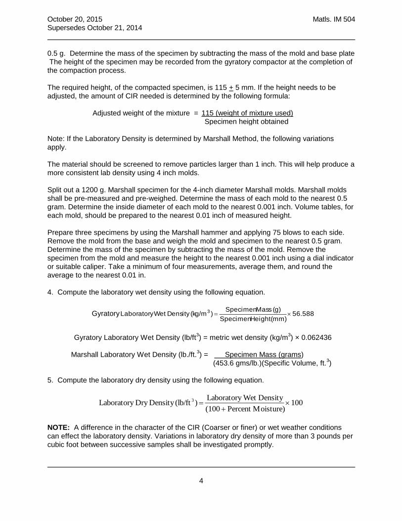
October 20, 2015 Matls. IM 504
Supersedes October 21, 2014
4
0.5 g. Determine the mass of the specimen by subtracting the mass of the mold and base plate
The height of the specimen may be recorded from the gyratory compactor at the completion of
the compaction process.
The required height, of the compacted specimen, is 115 + 5 mm. If the height needs to be
adjusted, the amount of CIR needed is determined by the following formula:
Adjusted weight of the mixture = 115 (weight of mixture used)
Specimen height obtained
Note: If the Laboratory Density is determined by Marshall Method, the following variations
apply.
The material should be screened to remove particles larger than 1 inch. This will help produce a
more consistent lab density using 4 inch molds.
Split out a 1200 g. Marshall specimen for the 4-inch diameter Marshall molds. Marshall molds
shall be pre-measured and pre-weighed. Determine the mass of each mold to the nearest 0.5
gram. Determine the inside diameter of each mold to the nearest 0.001 inch. Volume tables, for
each mold, should be prepared to the nearest 0.01 inch of measured height.
Prepare three specimens by using the Marshall hammer and applying 75 blows to each side.
Remove the mold from the base and weigh the mold and specimen to the nearest 0.5 gram.
Determine the mass of the specimen by subtracting the mass of the mold. Remove the
specimen from the mold and measure the height to the nearest 0.001 inch using a dial indicator
or suitable caliper. Take a minimum of four measurements, average them, and round the
average to the nearest 0.01 in.
4. Compute the laboratory wet density using the following equation.
Gyratory 56.588(mm) Height Specimen
(g) Mass Specimen )(kg/mDensity WetLaboratory 3
Gyratory Laboratory Wet Density (lb/ft3) = metric wet density (kg/m
3) × 0.062436
Marshall Laboratory Wet Density (lb./ft.3) = Specimen Mass (grams)
(453.6 gms/lb.)(Specific Volume, ft.3)
5. Compute the laboratory dry density using the following equation.
100Moisture)Percent (100
Density Wet Laboratory )(lb/ftDensity Dry Laboratory 3
NOTE: A difference in the character of the CIR (Coarser or finer) or wet weather conditions
can effect the laboratory density. Variations in laboratory dry density of more than 3 pounds per
cubic foot between successive samples shall be investigated promptly.

October 20, 2015 Matls. IM 504
Supersedes October 21, 2014
5
If the investigation determines the character of the CIR has changed, the corresponding dry
density result representing the lot shall be used. An identifiable difference in pavement may be
the cause of the change.
Unexplained variations or variations caused by rain, affecting the dry density by more than 3
pounds per cubic foot for successive Lots, shall be averaged with the previous days dry density
result. The average of both days will be reported as the dry density result representing the
current day’s lot.
FIELD DENSITY TESTING PROCEDURE
The project inspection personnel shall select and mark the field density test locations. Each
day of CIR production shall be divided into approximately equal sublots per IM 204. A random
location in each sublot shall be selected for moisture and density testing.
The Contractor will determine the in-place density and moisture using a nuclear gauge in direct
transmission mode at the maximum allowable probe depth in accordance with IM 334. The
nuclear gauge moisture measurements shall be adjusted by the correction factor below to
account for the asphalt binder in the mixture. The dry density and percent of lab density of
each test location is determined using the following equations. Report both values to one
decimal place. Sublots that do not achieve the specified minimum percent density should be
re-rolled immediately and re-tested. The optimum condition for re-rolling is when the CIR layer
is warm (typically in the afternoon). The Engineer may require adjustments to moisture
application rates.
Field Compacted Dry Density = Gauge Wet Density – Gauge Moisture + Correction Factor
100DensityDry Gyratory Laboratory
DensityDry Compacted Field Density Laboratory Percent
Example:
Field Compacted Gauge Wet Density 2090.6 = 130.5
Gauge Moisture -168.2 = -10.5
Correction Factor +120.2 = 7.5
Field Compacted Dry Density 2042.6 kg/m³ = 127.5 lb./ft.³
DETERMINE THE CORRECTION FACTOR
The first day, the Contractor will sample approximately 1000 g of CIR mixture at each density
test location (minimum of 10 locations) to determine the in-place moisture content. Each
sample shall be properly sealed, transported to the Contractor’s laboratory, and measured for
moisture content. Use the paired nuclear gauge moisture content measurements and in-place
(laboratory) moisture content measurements to determine the correction factor. Compute the
actual in-place moisture for each of the sampled test locations using the following equation.
100 Moisture % Laboratory
Density) Wet Guage(Nuclear Moisture) %y (Laborator )(lb/ft Moisture placeIn Actual 3
Example (for one set of paired values)

October 20, 2015 Matls. IM 504
Supersedes October 21, 2014
6
Nuclear Gauge Wet Density = 2090.6 kg/m³ (130.5 lb/ft³)
Laboratory % Moisture = 2.3%
33 2.9lb/ft102.3
300.2
100)(2.3
(130.5)(2.3)47kg/m
102.3
4808.38
100) (2.3
(2090.6)(2.3) Moisture place In Actual
Compute the average of the actual in-place moisture contents for the paired tests and compute
the average of the nuclear gauge moisture readings for the same moisture sample locations.
Then compute the correction factor using the following equation.
Correction Factor = Avg Gauge Moisture - Avg Actual Moisture
Example:
Average of Gauge Moisture 177.8 11.1
Average of Actual In-Place Moisture - 57.7 - 3.6
Correction Factor: 120.1 kg/m³ 7.5 lb./ft.³
Use Form #CIR-2, Determination of Moisture Correction Factor for showing the determination
of a correction factor. This correction factor may seem large. It represents the asphalt binder
in the CIR mixture. The nuclear gauge measures both asphalt binder and water in the moisture
reading.
NOTE: Any significant change in the characteristics or components of the asphalt pavement
being recycled requires a new correction factor.
DETERMINE RESIDUAL MOISTURE CONTENT OF THE PAVEMENT PRIOR TO CIR
Before the Contractor can place the HMA overlay or thin asphalt surface treatment over the
CIR, the moisture content of the CIR layer must drop to one of two specified levels:
1. 2.5%
2. 0.3% above residual moisture
The criterion for 0.3% above residual moisture recognizes the impact of the in-situ moisture
content of the pavement structure in a given location. If the residual moisture content is above
2.5%, that section of CIR layer may never achieve the standard 2.5% criterion.
To use the 0.3% above residual moisture criterion, the Engineer and Contractor should sample
and test the asphalt pavement prior to initiating the CIR production. The samples should be
taken at locations that represent the different drainage characteristics over the length of the
project. For example, cut sections and fill sections may have different residual moisture in the
top 3 to 4 inches of the asphalt pavement.
The samples should be taken during normal pavement conditions, not immediately after a rain
event. Postpone sampling until 5 calendar days after a rain.
Each sample must be cut dry. No wet coring. Dry sawing and impact air-hammers should be
used. The sample should represent the proposed depth of CIR rehabilitation. Immediately bag
and seal the samples and send them to the District Materials Lab to determine the residual
moisture content.

October 20, 2015 Matls. IM 504
Supersedes October 21, 2014
7
DETERMINE IN-PLACE MOISTURE CONTENT OF FINISHED CIR LAYER
The in-place moisture content must comply with specifications prior to applying a subsequent
HMA surface or thin asphalt surface treatment. Moisture content shall be determined for the
completed CIR layer in accordance with Materials IM 204 Appendix K. Two sample locations
should be tested from each day of completed CIR at the frequency established in Materials IM
204 Appendix K to determine the moisture content of the CIR layer. Inclement weather or
project conditions may require additional samples representing questionable areas to determine
acceptable moisture levels. When the average of the moisture test results satisfies the curing
criteria or no individual result exceeds the allowable residual moisture above, the layer is
considered cured.
If the Engineer adjusts the curing period, cores may be taken prior to check for excessive
moisture in the CIR as well as the underlying layers. When placing the first lift of HMA, rollers
may be restricted to static mode to avoid migration of moisture from underlying layers into the
new mat creating tenderness. When waiving curing criteria, responsibility for needed
corrections to damaged areas in the first lift should be mutually agreed upon prior to placement.
Moisture content of the material may be determined by one of the following methods.
1. Use the same nuclear gauge that was used for density determination taking into account
the moisture correction factor for asphalt content. The following equation will convert the
nuclear gauge readings to percent moisture.
100)kg/m or (lb/f t f actor correction )kg/m or (lb/f t moisture guage)kg/m or (lb/f tdensity wetguage
)kg/m or (lb/f t f actor correction - )kg/m or (lb/f t moisture guage Moisture %
333333
3333
Example: %Moisture = (9.1 lb/ft3 - 7.5 lb/ft
3) x 100 = 1.3
(130.5 lb/ft3 - 10.5 lb/ft
3 + 7.5 lb/ft
3)
2. Using a different nuclear gauge and establishing a new correction factor using the
procedure previously noted under field density testing.
3. Extract 1000 g of material from the sample location. Dry the entire sample to a constant dry
mass in an oven at a temperature not to exceed 275ºF (135ºC) or on a hot plate at a low
temperature setting.
FIELD REPORT
Report daily results on Form #CIR-3, Daily Cold-In-Place Asphalt Recycling Report. All CIR
forms can be found in the Asphalt Section of the Iowa DOT Web Page
(www.dot.state.ia.us/materials/acc.htm).

October 20, 2015 Matls. IM 504 Supersedes October 21, 2008 Appendix A
1
MIX DESIGN METHOD FOR CIR WITH FOAMED ASPHALT The mix design for CIR with foamed asphalt is performed by the Iowa DOT Central Laboratory. The primary steps in the mix design process are:
Determine the optimum foaming characteristics of the asphalt binder. Determine the optimum moisture content of the RAP for compaction. Prepare, compact, and cure CIR mixture over a range of foamed asphalt contents Determine the optimum foamed asphalt content for the CIR mixture.
1. DETERMINE THE OPTIMUM FOAMING CHARACTERISTICS By foaming the asphalt binder, the viscosity of the asphalt is significantly reduced to permit uniform mixing with cold RAP material. The ability to foam asphalt is controlled by the asphalt binder temperature and the amount of water injected into the asphalt. These values generally range from 280 to 320ºF (135 to 160ºC) and 1.5 to 3.5% injected water. The foamed is measured by the expansion ratio and half-life. The foam expansion ratio will increase (5 times to 15 times) as the amount of water injected increases. The half-life of the foam decreases (15 seconds to 5 seconds) as the amount of water injected increases. These conflicting conditions are merged to select the best foam properties for the project. An expansion ratio of 10 and half-life of 10 seconds are suitable for most CIR projects. The specification sets the temperature and injection water at values that are acceptable for most binders used for CIR in Iowa when a mix design is not performed. 2. DETERMINE THE OPTIMUM COMPACTION MOISTURE CIR mixture is compacted to a maximum density through the lubricating affect of the free moisture in the mixture. This is not the moisture injected into the asphalt binder to create foam. To determine the optimum compaction moisture, a group of RAP samples are compacted with different moisture contents. The resulting dry densities are plotted to determine the optimum moisture required for compaction. Mix designs prepared over the last several years indicate that the moisture required to achieve maximum RAP density is approximately 4 percent. Once the optimum moisture content is determined, the value is adjusted down slightly to account for the foamed asphalt added to the mixture 3. PREPARE MIXTURES The bulk sample of RAP may require additional processing to achieve a gradation that passes the 1 inch (25 mm) sieve. The RAP is dried in open pans at room temperature, sieved into 3 size fractions (+3/8 inch, +1/8 inch, pan) and re-blended to achieve uniform samples. Prepare a blending chart to determine what amounts of foamed asphalt will be added to the RAP. A minimum of three foamed asphalt contents should be selected. The preferred contents are 1.5%, 2.0%, 2.5%, and 3.0%. Each batch should have sufficient mixture to compact three 4 inch gyratory samples. The dry RAP sample and compaction water are added to the mixing bowl and mixed for 45 to 60 seconds. The foamed asphalt is sprayed into the damp RAP while the mixer continues to mix the sample. Continue mixing for an additional 60 seconds.

October 20, 2015 Matls. IM 504 Supersedes October 21, 2008 Appendix A
2
4. COMPACT AND CURE MIXTURES The gyratory compactor is used to compact each sample to 25 gyrations. Extrude the specimen and place it in the oven to cure at 105ºF (40ºC) for 72 hours. Remove the specimens from the oven and allow them to cool to room temperature. 5. TEST MIXTURES Measure the volume and mass of each specimen and determine the density. Sort the specimens into equal sublots based on height and density for further testing. Dry condition the samples of one sublot in an oven at 77ºF (25ºC) for 2 hours. The other sublot of specimens are placed in a 77ºF (25ºC) water bath for 20 minutes, vacuum saturated (50mm Hg) for 50 minutes, and then allowed to rest in the 77ºF (25ºC) bath for an additional 10 minutes. Perform the indirect tensile test (IDT) and calculate the average IDT strength for each sublot. Plot the average IDT wet and dry strength for each foamed asphalt content. 6. MIX DESIGN REPORT The mix design report will provide the results for optimum foam characteristics, optimum compaction moisture content, and optimum foamed asphalt content. Specific report values include: Asphalt binder temperature for foaming (ºF or ºC) Percent injection water for foaming (% of asphalt by weight) Optimum compaction moisture content (% of dry RAP by weight) Optimum asphalt foam content (% of dry RAP by weight)

October 20, 2015 Matls. IM 504 Supercedes October 21, 2008 Appendix B
1
MIX DESIGN METHOD FOR CIR WITH ENGINEERED EMULSION The mix design for CIR with engineered emulsion is performed by the Contractor. The primary steps in the mix design process are:
Process, dry, sieve, and blend the RAP. Select the engineered emulsion. Prepare, compact, and cure CIR mixture over a range of emulsion contents. Determine the engineered emulsion content for the CIR mixture.
1. PREPARE THE RAP SAMPLE The bulk sample of RAP may require additional crushing to meet the gradation band shown. The RAP is dried in open pans at room temperature, sieved into a minimum of 3 size fractions (+3/8 inch, +1/8 inch, pan) and re-blended to achieve uniform samples.
Sieve Size %passing
1.5 inch (37.5 mm) 100
1.0 inch (25 mm) 100
3/4 inch (19 mm) 85-95
No. 4 (4.75 mm) 40-55
No. 30 (600 µm) 5-15
No. 200 (75 µm) 0.5-3
2. SELECT THE ENGINEERED EMULSION Standard asphalt binder grades used for asphalt emulsions may not have appropriate characteristics to achieve the desired CIR mixture properties. By trial and error, the designer must select the base asphalt grade for the emulsion. 3. PREPARE MIXTURES Prepare a blending chart to determine what amounts of engineered emulsion will be added to the RAP. A minimum of three emulsion contents should be selected. The preferred contents are 2.0%, 2.5%, 3.0% and 3.5%. In addition to the engineered emulsion, 1.5% water is added to represent the water used in the milling process. The dry RAP sample and 1.5% water are added to the mixing bowl and mixed for 45-60 seconds. The engineered emulsion is added to the damp RAP while the mixer continues to mix the sample. Mixing continues for an additional 60 seconds. A set of three specimens can be prepared in each batch. 4. COMPACT AND CURE MIXTURES Specimens shall be compacted immediately after mixing. Do not use paper disks. Specimens shall be compacted with a gyratory compactor in a 4-inch mold at 1.25 degree angle, 87 psi (600 kPa) ram pressure, and 30 gyrations. The mold shall not be heated. Extrude specimens from molds immediately after compaction. Place each specimen in a small container to account for material loss from the specimens during curing. Cure compacted specimens in 140ºF (60ºC) forced draft oven for 48 hours. After curing, cool specimens at ambient temperature for 12 hours.

October 20, 2015 Matls. IM 504 Supercedes October 21, 2008 Appendix B
2
5. TEST MIXTURES
A. Determine bulk specific gravity (density) of each compacted (cured and cooled) specimen according to ASTM D 2726 or equivalent; however, the mass of the specimen in water (measurement C) should be recorded after 1 minute of submersion.
B. Determine specimen heights according to ASTM D 3549 or equivalent. Alternatively, the height can be obtained from the gyratory compactor readout.
C. Sort the specimens into equal sublots based on height and density for further testing.
D. For the three specimens of one sublot, determine corrected Marshall stability by ASTM D 1559 Part 5 at 100ºF (40ºC) after 2 hour temperature conditioning in a forced draft oven. This testing shall be performed at the same time that the moisture-conditioned specimens are tested.
E. For the three specimens from the other sublot, vacuum saturate to 55% to 75%, soak in a 75ºF (25ºC) water bath for 23 hours, followed by a 1 hour soak at 100ºF (40ºC). Determine corrected Marshall stability.
F. Compute the retained strength as the average moisture conditioned Marshall stability strength divided by the average dry Marshall stability strength.
G. Perform the thermal cracking test for critical cold temperature. The temperature is based on FHWA LTPPBind software for 50% reliability at 3 inches below the pavement surface. The required temperature for the specification is –20ºC. Perform the indirect tensile testing according to AASHTO T 322 with the following exceptions: 1) Specimens shall be 6 inches in diameter and at least 4 1/2 inches (115 mm) in height and compacted to the design density and emulsion content determined from the Marshall Stability Testing. Trial specimens are needed to establish the number of gyrations for
compacting the 6-inch specimens. Test specimens shall be cured at 140ºF (60C) for 72 hours. After curing, two specimens shall be cut from each compacted specimen to 2 inches in height. 2) Measure the bulk specific gravity of each cut specimen. 3) Test two specimens at each of three test temperatures (-20ºC, -10ºC, 0ºC). 4) The tensile strength test shall be carried out on each specimen directly after the tensile creep test at the same temperature as the creep test. 5) The critical cracking temperature is defined as the intersection of the calculated pavement thermal stress curve (derived from the creep data) and the tensile strength line (the line connecting the results of the average tensile strength at the three temperatures).
H. Perform the raveling test. The apparatus used for the raveling test is a modified A-120 Hobart mixer and abrasion head (including hose) used in the Wet Track Abrasion of Slurry

October 20, 2015 Matls. IM 504 Supercedes October 21, 2008 Appendix B
3
Surfaces Test (International Slurry Seal Association; ISSA TB-100). The rotation speed for the raveling test is not modified from ISSA TB-100. The ring weight is removed from the abrasion head for the raveling test below. The weight (mass) of the abrasion head and hose in contact with the specimen should be 1.3 pounds ± 0.5 ounce (600 g ± 15 g). The prepared sample must be able to be secured under the abrasion head, and centered for accurate result, allowing for free movement vertically of the abrasion head. The device used for securing and centering the sample must allow a minimum of 3/8 inch (10 mm) of the sample to be available for abrasion. The Hobart mixer will need to be modified to allow the sample to fit properly for abrasion. The modification may be accomplished by adjusting the abrasion head height, or the height of the secured sample. A Raveling Test Adapter can be purchased through Precision Machine and Welding, Salina, KS (785) 823-8760. Please reference the Hobart Model number A-120 when ordering. The C-100 and N-50 Models are not acceptable for this test procedure due to differences in size and speed of rotation. 1) Prepare two samples at the design moisture content and emulsion content. The size of each sample should be sufficient to meet the compacted specimen dimensions described below. (note: 6 pounds is an approximate weight (mass) to meet the criteria). 2) After mixing, place the mixture into a 6 inches (150 mm) gyratory compaction mold and compacted to 20 gyrations. The compacted specimen height shall be 2 3/4 inches ± 1/4 inch. 3) Extrude the samples from the compaction mold and placed on a flat pan to cure at a temperature of 50ºF +/- 2ºF (10ºC +/- 1ºC) for 4 hours ± 5 minutes. 4) The specimens shall be weighed after curing, just prior to testing. 5) The specimens shall be placed on the raveling test apparatus. Care should be taken that the specimen is centered and well supported. The area of the hose in contact with the specimen should not have been previously used. It is allowable to rotate the hose to an unworn section for testing. The abrasion head (with hose) shall be free to move vertically downward a minimum of 1/4 inch (5 mm) if abrasion allows. 6) The samples shall be abraded for 15 minutes and immediately weighed. 7) The percent raveling loss shall be determined as follows:
100Test Before Weight
Abrasion) After Weight- Test Before (Weight Loss Raveling
8) The average of the two specimens shall be reported as the Percent Raveling Loss. There should not be a difference of 0.5% Raveling Loss between the two test specimens for proper precision. A difference of > 0.5% will require the test to be repeated. If both of the samples have a Raveling Loss of > 10% the numbers shall be averaged and the precision rule will be waived.
I. Determine if the selected engineered emulsion within the emulsion content range tested meets the following properties. If not, repeat the design with another engineered emulsion.

October 20, 2015 Matls. IM 504 Supercedes October 21, 2008 Appendix B
4
Test Criteria Purpose
Marshall stability 1,000 lb. min. Stability under traffic
Retained strength 70% min. Ability to withstand moisture damage
Thermal Cracking -20ºC max. Resist low temperature cracking
Raveling Test 2% max. Raveling Resistance
6. MIX DESIGN REPORT The mix design report will provide the following results at the optimum engineered emulsion content: Engineered emulsion base asphalt PG grade RAP gradation Mixture dry density (lb/ft3) Marshall stability (lb) Percent retained strength (%) Critical low temperature (C ) Percent raveling loss (%)
