radio controlled soaring digest march 2018 (pdf) · as is always the case, rcsd has ... as you see....
TRANSCRIPT

SoaringDigestRadio C ntrolled
March 2018 Vol. 35, No. 3

2 R/C Soaring Digest
4 An Innovative Method for Acoustically Rendering Climb Data for Model Gliders Using Shepard TonesMapping two different altitudes which are hard to separate optically by way of two different tones with nearly equal pitches which otherwise can hardly be distinguished. By Helmut Stettmaier.
8 2nd Annual F5J Trophy EventText and photo coverage of the November 2017 event held at the NAAS field just outside Canberra on the first weekend in November 2017. Reprinted from Electric & Glider FLIGHT Australia, No. 11, January 2018, pp. 3-7, Peter Pine, Editor.
14 Millennium Cup Goes ElectricBy Colin Woodward. Reprinted from Electric & Glider FLIGHT Australia - No. 11 - January 2018, pp. 12-13, with complete rules included.
George Clarke landing his Strega 18A photo by Ian Cummings.
Florida Soaring Society FSS#1 19Text and photo coverage of the recent Florida Soaring Society event in Christmas, Florida, late January.
Dover partners with AFRL to innovatein fuel efficiency 37The Air Force Research Laboratories adds Microvanes to the rear of a C-17 at Dover Air Force Base.
PSS CandidateHawker Hunter 39A very streamlined and graceful aircraft with relatively small engine intake openings and a large wing area.
Front cover: Peter Kircher's Xplorer coming in for a landing over a field of colorful wild flowers. Photo by Marko BuBi Velickov.Nikon D7100, 1/1600 sec., f5.3, 140mm
March 2018Vol. 35, No. 3
CONT
ENTS
Back cover: Helmut Stettmaier captured this image in early September 2007 during the first sunny day after a period of bad weather. The location is in Switzerland at 46°30'30.13"N, 9°39'31.45"E, viewing to the East. Panasonic DMC-FZ8, ISO 100, 1/320 sec., f5.6

March 2018 3
R/C Soaring DigestThe journal for RC soaring enthusiasts
March 2018Volume 35 Number 3
Managing Editors, Publishers Bill & Bunny (B2) KuhlmanContact [email protected]
http://www.rcsoaringdigest.comYahoo! group: RCSoaringDigest
FaceBook: https://www.facebook.com/RCSoaringDigest/
R/C Soaring Digest (RCSD) is a reader-written monthly publication for the R/C sailplane enthusiast and has been published since January 1984. It is dedicated to sharing technical and educational information. All material contributed must be original and not infringe upon the copyrights of others. It is the policy of RCSD to provide accurate information. Please let us know of any error that significantly affects the meaning of a story. Because we encourage new ideas, the content of each article is the opinion of the author and may not necessarily reflect those of RCSD. We encourage anyone who wishes to obtain additional information
to contact the author.
———
Copyright © 2018 R/C Soaring DigestPublished by B2Streamlines
http://www.b2streamlines.comP.O. Box 975, Olalla WA 98359
All rights reserved
———
RC Soaring Digest is published using Adobe InDesign CS6
In the AirWe related some of the many advancements in electronics and construction materials and methods as they are related to RC soaring in the October 2017 edition of RC Soaring Digest. This month RCSD highlights a creation which has the potential to dramatically change how we interpret RC sailplane changes in altitude. Helmut Stettmaier has taken miniaturized electronics, computer programming, and an auditory illusion to create a quite astounding altimeter for use in just about any RC soaring environment.We encourage RCSD readers with an interest in this technology, or who simply have words of encouragement, to contact Helmut directly at <[email protected]>.Articles with a technical bent are always welcome here at RCSD, whether it be related to weather, an electronic device, model construction materials and techniques, photography or an acquirable RC soaring skill. As is always the case, RCSD has an immense and worldwide readership, so help with writing and editing are readily available. If you only have a topic in mind or have already started putting words to paper or into a computer and can use some assistance, contact us through our email address <[email protected]>.High resolution photos for use on the RCSD front and rear covers are always desired, as are event coverage materials, ideas for future PSS and aerotow candidates, travelogues... Anything related to RC soaring. And the deadline is always the 15th of the month prior to the cover date.Time to build another sailplane!

4 R/C Soaring Digest
The situation is commonly known: You have your glider flying in a weak, narrow, perhaps also a bit patchy, thermal and nothing better is here. You try to figure out if the variometer signals more climbing or more sinking. In longer time intervals you check the altitude regularly to get at least “some balance.” This of course should be done with an easier and more intuitive method.In such cases the exact question is not “Does the bird climb?,” but “Have I gained altitude?“ - a quite fine distinction but it is always a good idea to answer the exact question. In instances comparable to the ones described above, it should be better to render the altitude of the glider instead of its climb rate, with high definition and, of course, with as short a delay as possible. The tone pitch indicates the altitude; constant pitch means constant altitude.Most persons, including the non-musical ones, really can distinguish tone pitches regarding higher/lower and, after some training, can even remember them for comparison over short time periods. Therefore this rendering method appears best when at the end of a circle you want to know if the glider is flying higher than “one round before.“ In other words, if the circle “has given a good return.”Of course this does not work so simply. A woman or man with “normal“ hearing has only one octave within which she or he can distinguish pitches when the context is more technical, not musical. So you cannot render all altitudes being flown with a simple tone. There are not so many different tone pitches
and the human ear could never perceive, distinguish and meaningfully interpret all this. Two different tones with nearly equal pitches, such that they can hardly be distinguished, should be mapped to two different altitudes which are hard to separate optically. You hear as good as you see. How close such tones may be is different for each individual. This depends on the individual’s innate hearing ability and, of course, on training. I have, for example, found that I can marginally separate two tones with a difference in pitch of about 1/50th of an octave.About five such tone steps, meaning about 1/10th of an octave (or a bit more than a half tone in music), may be viewed as clearly distinct and should represent a small, but also clear
Editor addition: An octave (Latin: octavus: eighth) or perfect octave is the interval between one musical pitch and another with half or double its frequency. — Wikipedia definition. On the A440 musical scale, key has a frequency of 440 Hz, key (one octave below) 220 Hz, key (one octave above) 880 Hz. Image <https://en.wikipedia.org/wiki/File:Klaviatur-3-en.svg>.
An Innovative Method for Acoustically Rendering Climb Data for Model Gliders Using Shepard Tones
Helmut Stettmaier, [email protected]

March 2018 5
difference in flight altitude. I consider about ½ or 1 meter (~1.5 – 3 feet) as adequate. Using this assumption, one octave should represent between 5 and 10 meters (~15 – 30 feet) altitude difference.How shall we map about 2500 meters of altitude which could be flown with a model glider from the Netherlands up to those wonderful alpine slopes on such a limited set of tones? The idea is very simple: We reuse tone pitches after a few meters. When the model glider has gained some meters in altitude and the tone pitch has climbed we restart from one octave lower and vice versa when losing altitude. The mapping then becomes ambiguous. Layers of altitude are defined and only within such a layer the tone is unambiguous. The height of a single layer corresponds to one octave. When the layer is high enough the ambiguity does no harm as it suffices for the purpose of this rendering: The model pilot is informed about altitude changes in quite a narrow range over a short time.Regarding all this I define: An octave represents 8 m (~25 feet) altitude difference and about 30 - 50 cm (~12 – 20 inches) altitude difference can be “clearly heard,” such that about 50 different tone pitches per octave should be foreseen. Technically, 64 different tones is a good choice as 64=2^6 is still a “holy number“ for programmers of small computers and narrow banded data transfer.In cases of steep climb or descent, such an acoustic rendering becomes unusable as the tones can no longer be allocated to layers. There are three scenarios: (1) uninterrupted climb and the problem is to optimize climbing, the first question “does it climb?“ is now posed and the traditional variometer is the better choice. Or (2) the glider has a wild, turbulent ride and no aid concerning rendering climb or descend is possible. Or, (3) most wonderful, you are converting potential energy into kinetic energy featuring aerobatic and other rather dynamic maneuvers. Here in Bavaria we sometimes say “Abfetz’n“
[‘abfɛʦn], and you simply switch off any tone and enjoy the flight.Finally, we must cope with the step in pitch at the borders of the altitude layers: The two tones are “the same ones,“ comparable to a’ and a,” but the frequencies being one octave apart differ by the factor 2 and such a step will disturb the pilot, especially when the glider moves close to a layer boundary and crosses it frequently. There exists a solution which is easily to implement nowadays. It was introduced about 50 years ago by the cognitive scientist Roger Shepard using some technical efforts and which has been named the Shepard Tone. If you want to learn more about this subtle invention simply google “Shepard Tone illusion.“Shepard mixed several harmonics - “same” tones separated only by octaves; that means an “nth harmonic” tone has a frequency of 2^n times the base frequency. When the tone rises, the uppermost harmonic fades out and a new tone of ½ of the base frequency fades in. This is demonstrated quite
Graphical representation of tones generated by standard “rate of climb” variometer versus the “relative height” Shepard Tone.

6 R/C Soaring Digest
clearly in [yt]. It is easier to understand this by viewing this video, beginning at 0:41, than by reading (and writing). Using such tones you can generate a sound which apparently rises or descends in pitch infinitely, ideal for our rendering task. Super Mario players perhaps know this tone from the scene, when the hero must run upstairs endlessly. This scene may also be seen in [yt]. I have implemented such a tone illusion digitally by mixing only two tones. This suffices perfectly and one “cycle“ simply represents one octave or one altitude layer, respectively.The included picture contains about six seconds of a recorded flight. It corresponds to the video clip I mention later. The abscissa is the time. As this section of the flight is shown twice in the video there are two scales: The blue one corresponds to the Shepard Tone rendering and the blue curves, the red one to the traditional variometer tone rendering and the red curve respectively. Remember that these 6 seconds show the same section of the real flight. The ordinates are the altitude (left) and the tone frequency (right). The three blue curves are a visualization of the Shepard Tone. The darker the color the more the tone is mixed into the Shepard Tone; see, for example, the time at 14. Here the middle tone is dominant. In the second from 15 to 16 the tone is mixed with the one at 400 - 500 Hz (a bit louder) and the other from 800 - 1000 Hz. In this simulation the layer’s height is 6.4 m and the glider moved through about 1½ layers.The red curve is, together with the zero-line, a traditional variometer tone. The curve is shifted about 0.15 seconds to the right as my variometer is not as fast as my altimeter – this is common to nearly all such devices. This curve shows two times climbing with different intensity and two times descending. Relying on this information - which would have to be “integrated” during flight - it is nearly impossible to estimate if the glider has gained altitude during these 6 seconds or not. But the Shepard Tone signals a climb.
It is possible to compensate the altitude rendering against the air speed by using an appropriate total energy probe (Irving tube, Braunschweiger Düse, see also RCSD 1988/9 page 17) as with traditional variometers. It is essentially the same problem and the same solution. But, before using such compensation, you should ask the correct question: “Does the air rise there?” or “Has my glider gained some altitude?”Aeromodelers flying large scale gliders far away over a valley might not be so impressed by the Shepard Tone rendering. We are discussing how to climb in smaller steps under difficult conditions in rather narrow spaces. The Shepard Tone does not replace the traditional variometer. But it is, in my opinion, a perfect supplement for many circumstances.There are aeromodelers who can see tiny movements of a model glider at 200 m distance, can find correct conclusions and bring that bird up. I admire this but do not possess such skills as I would like to. By far not. Variometers were, from the beginning on, very important for me and many others and I owned some of them. But over the last two years, as I prove the Shepard Tone rendering concept and have become familiar with it, my “thermal skills” have improved significantly, and this is not only caused by the increasing quality (and prices) of my gliders. I also can find my way up with my older, simpler aeromodels. This rendering has become a bit of a new sense for me and I really enjoy it.An aeromodelling altimeter must fulfill some quality prerequisites to be usable for Shepard Tone rendering. The noise canceling for the pressure sensor must be of very good quality and must, importantly, work very quickly. Recent advances in microcontroller electronics and a 200 year old error canceling method (Gauss’ least squares method) can yield small miracles. For the Shepard Tone rendering the fast working - measurement, noise cancelation, transmission and rendering - of the system is important as the results can be compared directly to visual acquisition when the aeromodel is clearly

March 2018 7
visible and large delays do really disturb recognition. When the model performs a close fly-by and does a small “hop,” the rendering should resemble the “hop” as close as possible. In this context, 0.3 second delay is a long time.Devices featuring this altitude rendering cannot be bought today. I use equipment which I have designed and built by my self and is based on two components: • a high definition and really quick altimeter which uses a non-standard data format to yield the altitude to the M-Link® RC-equipment to be transmitted downwards with high priority, and • a “render engine” that can be connected to the RC transmitter. It generates traditional variometer tones and Shepard Tones to be selected by the user and has a rudimentary speech output and some haptic rendering, but this is not part of this article. It is mostly constructed of standard modules. In this case NUCLEO and Adafruit parts.To offer an impression of what I have written I prepared a tiny video of 27 seconds length of a dynamic slope flight. See the link under [hs]. The original recording has a very bad sound quality and, of course, only one type of sound, many plops of the wind and also a few comments from my beloved Erni, and does not allow a comparison between the two acoustic renderings. Therefore I reconstructed the altitudes and generated a new stereo sound track on the PC. It fits the real
flight very well. The right channel contains the traditional vario tone with four different modulations for steep or light descent and for light or exciting climb. The left channel contains the Shepard Tone. A section of 6 seconds which correspond to the picture, is contained twice in the video, the first time with a variometer tone, the second time with the Shepard Tone.Perhaps you may wonder why I wrote this article and offered it to RC Soaring Digest when the hardware and software is simply not available. At first there is an invitation: Make it available! I can help with software, making better altimeters, generating Shepard Tones – nearly free of bugs. A very first step could be to equip a flight simulator with this rendering, although thermal climb under difficult conditions is not often simulated perfectly. If someone wants to build something, my email address is at the top of this article.Links:[yt]: <https://www.youtube.com/watch?v=LVWTQcZbLgY>[hs]: <https://youtu.be/M48G_gsW31o>Author web site: <http://stettmaier.de/>M-Link® is a registered trademark of Multiplex GmbH, Bretten, Germany.Copyright ©2017, 2018 by Helmut Stettmaier. All rights reserved.
The author and his Typhoon Plus 3000 at Alp Giop (St. Moritz – Corviglia), Switzerland.

8 R/C Soaring Digest
The F5J Trophy event held at the NAAS field just outside Canberra on the first weekend in November 2017 proved to be a great success, run to overseas protocols learned in Slovakia; 6m safety corridor, ready box strategy, and a continuous sound file. The safety corridor allowed easy access to and from the field. Fliers were banned from flying over the safety corridor lower than 10m, and prohibited from landing in the corridor. Fliers launched from the upwind side of the safety corridor on the hooter, and then moved back to their spot 21m behind them. As the corridor was cleared fairly early in each heat, the fliers for the next heat could access the corridor and prepare for the next flight even before that heat had finished. Fliers gathered in the ready box at the pits end of the safety corridor while the heat before them was flying, so they were ready to proceed to their marked take-off spot (the draw allocated take off location as well as group to be flown) as the previous group was finishing up. They needed to do this as there was no waiting between groups flying. As
soon as one group finished, 5-minutes’ preparation time started for the next group as indicated in the rules. Thanks to Trevor Smith’s skill with computer files, he was able to modify the Gliderscore file to provide this continuous, repeated calling of preparation and flight time. Several warnings were given during the countdown of preparation time (2 minutes to go, 30 seconds to go), and the horn sounded to start the next heat right at the end of the prep. time. This made
Marcus Stent, gracious winner of the F5J Trophy 2017. His name goes on the perpetual trophy, and he picked up a serious power supply unit courtesy of sponsor Dave’s Toys for Big Boys - support the guys who support our sport!
2nd Annual F5J Trophy Event Reprinted from Electric & Glider FLIGHT Australia, No. 11, January 2018, pp. 3-7
Peter Pine, Editor, [email protected]

March 2018 9
for a very smooth running event with no delays. The whole process was aided by the new AEFA sandwich board that displayed “round” and “group” in large, 40mm high numerals, double sided so that it could be read from the pits or from way out on the field; there was no confusion about which group was flying. Consequently, 9 rounds were flown in 1.5 days with 32 fliers (8 or 9 per
group). Fliers came from all eastern mainland states to give a good interstate representation. Saturday flying commenced in idyllic, calm conditions and fliers had to fly gently to eke out a good time in the calm conditions, but the wind built up dramatically during the day. Some were concerned about the wind reaching something like 25 km/hr, but Marcus Stent encouraged us to keep flying and
learn how to cope with wind, or we will always be stopping events as soon as the wind builds up a bit. Apparently the FAI wind limit is something like 36 km/hr! I certainly learned a good lesson, as I followed lift downwind twice in the extreme conditions, and even though I was flying a slippery model, it was lightly loaded at 1.3kg and could not get back to the spot. I had to start my motor to bring the model home - thank heavens for “emergency motor restart”!
Above: Alan Mayhew from Melbourne prepares to launch his Xplorer.Right: Col May came all the way from Bundaberg to fly his Pike Perfection. Phil Stevenson timing.

10 R/C Soaring Digest
Sunday was much better, and even though the wind did build up somewhat, it was nothing like Saturday. Flying concluded about 1:30pm with 9 rounds under our belt, and provided for a more relaxed pack up and presentation. Marcus Stent from Melbourne gave an amazing performance to take out the event with a borrowed model; a 3.2m Prego designed by Alan Mayhew to introduce his club members to an aileron glider. This was the prototype all-balsa model, and Marcus had never flown F5J before (though he has developed considerable thermal-finding skills flying F3K). Marcus’ skill at finding thermals was commensurate, and he graciously gave a seminar after the flying concluded and gave away some of his secrets. Many of his ideas are based on Joe Wurts’ third vector theory, but I have heard Joe try to explain his theory before and could not fully understand it. Marcus put things in layman’s terms and it was quite clear. In fact, Marcus has written up his thoughts on thermal finding and we have published his paper on the AEFA web site. Go to the home page and you will see a link. Second place in Open F5J went to another home-built model, a 3.6m Avatar assembled by Phil Bird. Phil is a great flier with many years of F3B experience, and it shows. Phil has returned to flying to give F5J a go, and he is doing amazingly well. He gave all of us a shake up at the Picton Cup event near Sydney flying a homebuilt “Inside”, and now he has taken 2nd at the F5J Trophy! Watch this man! Third place in Open went to experienced flier from HSL, Jack Murphy. Jack is another flier who has transitioned to F5J from winch-launch glider, and now that he has practised the new class is also becoming a force to be reckoned with. Well done Jack! Limited F5J is always interesting and it was a great surprise to Rob Watson that he took out the class with his Radian (though not to most of us watching). Rob is much practised with his Radian and usually does very well flying a model that will not reach 200m in 30 seconds, and has no landing aids to help gain a spot landing bonus. The wind plays havoc with Radians, but
Ladislav Safarik launches his Stork with Stan Rucinski timing.
Ray Murray launches his Radian in Limited F5J.

March 2018 11
it was the same for all other Limited F5J fliers who struggled in the wind. Some of Rob’s flights were times like 2:14 and 2:46, and most were under 5:00 minutes, but so were lots of others flying in the wind. It is all about doing better than others in the conditions! Second place in Limited F5J went to Marius Baumgartner, also flying a Radian, and this was Marius’ first ever F5J event flying a borrowed model (must be a trend to borrow a model and take a place in an event - I must try it!!). Third place in Limited went to Ken Woodward flying another home-built model. Ken campaigns very well with his balsa models and enjoys it! Note the prevalence of smaller and home-built models in the results, and foam ready-to-fly Radians. Do I need to make this point again? It is not all about having the best model - it is all about being able to find thermals and land well! This accounts for the rapid growth of F5J that does not require high-tech equipment or great expenditure to be able to compete. Give it a try yourself. A report on the F5J Trophy event is not complete without giving credit to the NAAS club for providing a great site and great hospitality. The field is one of the best on which I have ever flown. The site is vast and caters for superb camping; the club has invested in buying their own toilets and setting them up on stands, and they have charging stations and 240V power available. A hot shower facility was added and is exceptional - we call it the Taj Mahal with wrought iron decoration and mirror provided! How many other clubs would go to this trouble to cater for visitors? And there is more; one of the on-site containers can be set up as a theatre and it was in there that we held a seminar on the Slovakian experience and were able to screen a Power Point presentation on the Saturday evening. If you have not already seen it, a link to a summary of the slides from the presentation are on the home page of the Australian Electric Flight Association (AEFA ) web site <http://www.aefanet.com/contacts>.
Hutton Oddy is flying a state-of-the-art light model from the Netherlands called El Nino.
Don Farrar launches his Stork at Canberra.

12 R/C Soaring Digest
Marius Baumgartner placed second in Limited F5J in his first event - seen here with father, Peter.
Gary Ryan made the trip from Melbourne for the event.
Stan Rucinski launches his Stork. Paul Gibson and his Stork. There were Storks everywhere. Must be a baby boom in Canberra!

March 2018 13
Peter Baumgartner, Marius’s father, has produced a great video of the F5J Trophy event and there is also a link to that on the home page of the AEFA web site - what a great source of information the web site is, all managed proficiently by David Lucas. Now, the third Annual F5J Trophy event is already scheduled for 3/4 November, 2018. Mark that in your diary and do not
miss the top F5J event in the country. And this year’s event will also act as one of the team selection trials to select the Aussie team to compete in the first ever F5J World Championship, scheduled for Slovakia in September 2019. That is only relevant to fliers who have already nominated that they are in contention for a place on the team; aspirants must nominate and pay a fee before competing in their first team selection
trail, and there will already have been two such events (Milang and Jerilderie). The event will not be any different because it is a team selection trial, and those of you not interested in team selection can continue with impunity!
Basic models won the F5J Trophy event. On the left is First Place finisher Marcus Stent’s Prego 3.2m. Phil Bird was second, flying his Avatar shown on the right.

14 R/C Soaring Digest
The Millennium Cup has been an extremely successful, simple, winch launch glider event for two-metre wingspan/two-function control models in NSW that has run for some 18 years. Seven rounds have been scheduled each year at different locations each time, and entrants did not have to attend all meetings - the best scores were taken for the results. The events have been organised each year by the Heathcote Soaring League club that is based at Maddens Plains, just south of Sydney. Numbers have been dropping slowly as adherents turn to electric gliding, so the organisers decided to change to electric gliders from 2018 on. Here is a letter from Col Woodward, HSL President, announcing the change: Due to increased interest in electric launch gliders, and to encourage new participants, we are going to use electric assisted launch gliders at the Millennium Cup contests, instead of winch launch models, from the beginning of 2018. Please find attached a set of rules for electric assisted models to be used at future Millennium Cup contests.
Millennium Cup Goes Electric Colin Woodward, [email protected]
Reprinted from Electric & Glider FLIGHT Australia - No. 11 - January 2018, pp. 12-13
To enter the Millennium Cup, chop the nose off your favorite 2m glider and add an outrunner, as in this image showing David Lucas with a Drifter 2 converted to electric with a Scorpion outrunner.
The ubiquitous Radian also suits the Millennium Cup - so dust off your trusty Radian - seen here in the hands of Ralph Dephoff.

March 2018 15
The electric assisted glider rules have been developed to keep the same simple, cheap and fun theme that the Millennium Cup has always tried to achieve. The electric model is essentially the same as the winch launch model but is allowed to have an extra radio channel to control the electric motor. The model will also require a height limiter to switch the motor off at 150m. To keep an even playing field, the power of the model will be roughly equal to the output of a standard Parkzone/E-Flight radian, 180watts (measured with the models fully charged normal flight pack after 10sec of continuous motor run). There will be a wattmeter made available in the Millennium Cup equipment box with various battery connectors for people to “self police” their models. Random tests may be conducted if the CD of the day or the Committee notices an obvious breach. The contest director will choose a launching spot which has no equipment or people upwind for safety. As planes are launched, the pilot and timer will reposition onto their landing spot. The contest director will have to “meter” launches depending on available landing spots. The electric assisted models will require their time keeper to start a watch when the model leaves the launcher’s hand. At 30 seconds the time keeper will announce that the motor should be turned off, if the pilot or limiter has not already done so. The pilot will need to fly for a total of 6min 30sec from when the model is released. Once the model has been released, no relaunches are allowed. If the motor is started again then the flight time will stop, there will be a 50 point penalty and no landing points. This is to try to mimic an out landing for a winch launch model and to deter flying for maximum time points when there is no chance the model will get back to the spot. A score will be submitted which includes total flying time up to 7 minutes (6 minute 30 seconds for maximum score), landing distance and motor re-run penalty if required. At no stage will an electric model be launched or motor started pointing towards people or the pits. Landing will be the same format as
the winch launch gliders. We welcome any comments as the competition is run to further improve the format. This set of rules will be made available on the Heathcote Soaring League Website: <http://hsl.org.au/> The full rules are included here, so check them out, dust off your 2m electric soarer, and give it a go.
Millennium CupCompetition Rules for
Electric Assisted Launch Gliders1 Model Specifications Electric Assisted Launch Glider i) Maximum Wing Span: 2000 mm ii) Maximum surface area: 150 sq DM iii) The model shall have only three channels used in its
radio receiver. iv) The underside of the model must not have any
protuberance other than surface control linkages and a propeller.
v) A radio-controlled glider is a model in which lift is generated by aerodynamic forces acting on surfaces remaining fixed except for control surfaces. No other propulsion devices may be used except for an electric motor driven propeller with total power not exceeding 180 watts (measured with the model’s fully charged normal flight pack after 10 sec of continuous motor run).
vi) An electronic height limiter will be used to switch the electric motor driven propeller off at 150m above launch ground level or 30 sec after launch, whichever occurs first, unless turned off sooner by the pilot.
vii) Only the pilot standing on the ground shall control the model. Control shall be by radio transmission to the model only.

16 R/C Soaring Digest
viii) The radio control equipment used must comply with current MAAA regulations.
ix) Any device for transmission of information from the model to the pilot is prohibited during the competition. Receiver battery voltage and signal strength are allowed.
x) Any other device or design not considered to be in the spirit of the competition may be prevented from use, at the Committee’s discretion.
2 Task and Fight Scoring Electric Assisted Launch Glider i) The objective of the contest is to complete a flight of 6
minutes pure thermal duration and land within 1 metre of a designated spot.
ii) There will be a 30 second allowance to run the electric motor driven propeller once at the start of the flight.
iii) One point will be awarded for each full second of the 6min 30sec flight from when the model leaves the launcher’s hand to the time the model comes to rest, up to a maximum of 390 points, i.e. 6 minutes 30 seconds maximum. No extra points will be given if the pilot does not use the full 30 seconds of launch allowance.
iv) One point will be deducted for each full second flown in excess of 390 seconds after the launch i.e. 6 minutes 30 seconds. After 7 minutes, the flight and landing shall be zero points.
v) Additional points will be awarded for landing, depending upon distance from the spot, marked by the Contest Director, according to the following tabulations:
vi) The distance is measured from the nose of the model to the spot. The measured distance is rounded up to the nearest highest metre.
vii) No landing points shall be awarded if the model touches any person during landing manoeuvres.
viii) The tape shall not be piled on the spot marker.3 Launching Electric Assisted Launch Glider i) All launching shall take place on a spot designated by
the organiser. The spot shall have no persons or equipment upwind for safety.
ii) Launching direction will be set by the Contest Director. At no time is the model to be launched towards people or the pit area.
iii) One continuous motor run will be allowed for a maximum of 30 seconds or up to a height of 150 meters, whichever occurs first.
iv) If a second motor run is required within a flight then the flight time will stop when the motor starts again and zero landing points will be available. A penalty of 50 points will also be applied.
4 Contest Scoring i) If four or five heats are flown, the competitor’s
classification is determined by the sum of all scores for each heat. If six to eleven heats are flown, the lowest score shall be deleted. If twelve heats are flown, then the two lowest scores shall be deleted.
ii) To decide the winner should there be an equal score after the appropriate low scores are dropped: a count back on flying time including landings of all heats shall decide the winner.
iii) A minimum of four heats shall be flown for a Millennium Cup Point Score event.
5 Millennium Cup Annual Scoring i) A competitor’s best four rounds shall be counted
towards the Millennium Cup.

March 2018 17
ii) The scores for each individual round shall be normalised using the “1000” system for the Millennium Cup.
6 Competitors and Helpers i) The competitor (pilot) must operate his/her transmitter
and fly the model personally. The pilot is solely responsible for the operation of their model.
7 Definition of an Official Flight and Pop Off i) If a timing malfunction occurs it will not be grounds for a
re-launch unless it is brought to the attention of the Contest Director within 30 seconds of it being known. The flight shall immediately be abandoned.
ii) No re-launch is allowed once the model leaves the launcher’s hand, unless an unexpected event occurs not caused by the pilot/launcher or their model. This shall be announced within ten (10) seconds of the unexpected event occurring.
8 Cancellation of an Official Flight or Disqualification i) Conduct that is not in the spirit of the rules may result
in the competitor being disqualified at the discretion of the Contest Director or Committee.
ii) The flight in progress is annulled if the model loses any part during the launch or during the flight time. The loss of a part during landing (i.e. in contact with the ground) is excluded.
9 Organisation of Contests i) The host club may appoint a Contest Director for their
contest. ii) A pilots’ briefing will be conducted prior to the
commencement of the contest, during which the objective of the competition, flying rules and any local safety advice will be explained. The Contest Director must clearly define the boundary between the landing area and the area assigned for other business (safety area).
iii) All relevant MAAA and CASA safety directives must be observed.
iv) Once the contest has started there shall be no test flying. v) Competitors are to launch as soon as the launch area is
clear and safe to do so on the Contest Director’s signal. vi) At the Contest Director’s discretion, models may be
flown out of normal sequence. vii) Should the pilots believe flying conditions are not in the
spirit of the Millennium Cup competition, a pilots’ briefing will be called at the end of that round. The majority vote will decide if the competition is to be paused or concluded at that point.
10 Junior Definition i) A person who enters the Millennium Cup competition
before their 18th birthday shall be deemed to be a junior for the remainder of the Millennium Cup rounds for that calendar year.
FAI Record Claim 29 January 2018=========================================Claim number : 18210Sub-class : F5 Open / Radio Control FlightCategory : AeroplaneGroup : Electrical Motor Rechargeable SourcesType of record : Distance to goal and return: 174Course/location : Pioche, Nevada (USA)Performance : 224,22 kmPilot : Gary B. Fogel (USA)Date : 28.07.2017Previous record : no record set yet=========================================FAI congratulates the Pilot on this splendid achievement.

18 R/C Soaring Digest
George Clarke uses the “crow” function to assist in landing his RCRCM 2.9m Strega. Photo by Ian Cummings of the Torrey Pines Gulls. “This one of my favorite images. George is a US Navy Retired Commando, and one of our regular pilots at the Torrey Pines Gliderport.”
Photo © Copyright Ian Cummings Photography

March 2018 19
Everything at the contest is in one “class”; everything from my 2m electric Spectra to the 3m composites flew together. The contest is a TD mixed-launch event with electrics and winch-launched aircraft competing together, with altitude limiters set at 150m for the electrics. Seven 7-minute rounds were flown on both Saturday and Sunday for the event, 14 rounds total. For this contest the CD (Raed Elazzawi) introduced a “mixed landings” approach which allowed — as an option — built-up, electric, and foam aircraft to use a mandatory sliding landing with no skegs with no nose-in “javelin” style landings allowed. The modified landing areas had slightly relaxed scoring tapes. Raed’s comments on the new idea are as follows:“There are going to be separate landing tapes for Electrics, built ups, and foamies. The tapes will be the same length as
our usual tapes, but the graduations will be 6 inches apart, compared to 3 inches, marked from 50 to 100 points. Landings on these tapes will be no dork, and no skeg.“Electrics, builtups and foamies will have their scores normalized in one group, dorkers will be normalized in a separate group, scores will be combined in the overall standings. “I am sure there will be growing pains, but with your cooperation and input we can make this work. The goal here is to get as close as we can to a level playing field, and hopefully we can entice more participation in our contests.”The Club’s website address is http://www.orlandobuzzards.org/ and the FSS is http://www.soar-fss.org/.
Scott Keating, [email protected]
Florida Soaring Society FSS #1Fort Christmas Field, Christmas, FloridaJanuary 20-21 2018

20 R/C Soaring Digest
White Xplorer with red trim, red Xplorer with white trim.

March 2018 21
Jody Miller catching. Mike Pogue preparing to launch a Radian XL.
Mike Naylor’s Shadow. Mike Gardner’s Xplorer.

22 R/C Soaring Digest
James Guillen’s Sprite.
March 2018 23
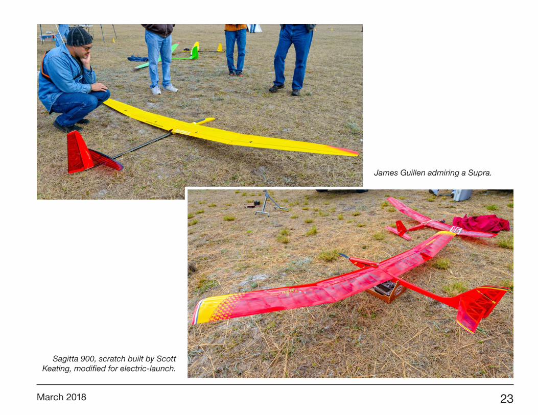
Sagitta 900, scratch built by Scott Keating, modified for electric-launch.
James Guillen admiring a Supra.

24 R/C Soaring Digest
Great Planes Spectra (2m span), built by Scott Keating, modified for electric-launch.
A Radian XL, 2.6m span.

March 2018 25
A Radian XL climbing out.

26 R/C Soaring Digest
Braydon Chamberlain ready for his Xplorer to be launched. Rick Eckel Launches his Kennedy Composites Supra.
Mike Garnder launches his Xplorer. Jody Miller launching.

March 2018 27
Rick Eckel’s Supra coming in.

28 R/C Soaring Digest
Steve Blake’s Xplorer.

March 2018 29
The underside of Paul Mittendorff’s Xplorer.

30 R/C Soaring Digest
Rick Eckel’s Supra in profile.
Steve Blake’s Xplorer.

March 2018 31
Jody Miller’s Xplorer nearly head-on.

32 R/C Soaring Digest
Steve Blake (pilot) and Jody Miller (timing).jpg.
Paul Mittendorff landing 2.
Jody Miller ready to catch his Xplorer.
Paul Mittendorff landing 1.

March 2018 33
Steve Blake’s Xplorer at the spot.

34 R/C Soaring Digest
Rick Eckel landing his Supra, Mike Pogue timing.

March 2018 35
Paul Mittenforff’s Xplorer soaring past.
36 R/C Soaring Digest
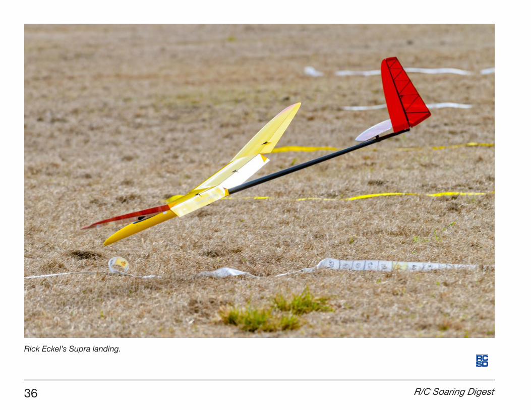
Rick Eckel’s Supra landing.

March 2018 37
DOVER AIR FORCE BASE, Del. — As Air Mobility Commands focuses on the innovations necessary to maintain the Air Force’s competitive advantage, Mobility Airmen provided insight to help the Air Force improve C-17 capabilities and save money in the future.The Air Force Research Laboratory’s Advanced Power Technology Office from Wright-Patterson AFB collaborated with Dover AFB Airmen and private companies on programs to make the entire C-17 Globemaster III fleet lighter, safer, and more fuel efficient on January 30, 2018.Programs currently being developed by APTO to improve the C-17 fleet include the installation of Microvanes.MicrovanesThe nylon Microvanes being tested are filled with 3D-printed glass beads. Each Microvane is 2.4 inches tall and 16 inches in length. The addition of Microvanes to the C-17s are an effort contracted with Lockheed Martin to reduce drag and fuel consumption that is currently being considered for transition by AMC.
VIRIN: 170906-F-BO262-1022736th AMXS personnel installed 12 Microvanes, six on each side, at the rear of a C-17A Globemaster III fuselage on September 6, 2017 at Dover AFB. The 3D-printed glass bead-filled nylon Microvanes are 2.4 inches tall and 16 inches in length. This is an effort to reduce drag and fuel consumption. (U.S. Air Force photo by Roland Balik/Released)A much larger, high-res version can be viewed or downloaded here: <https://media.defense.gov/2018/Feb/09/2001876084/-1/-1/0/170906-F-BO262-1022.JPG>.
Dover partners with AFRL to innovate in fuel efficiency Roland Balik436th Airlift Wing Public AffairsFebruary 09, 2018

38 R/C Soaring Digest
Using a Mylar template, 736th AMXS maintenance personnel installed 12 Microvanes, six on each side at the rear of a C-17 fuselage that gave Guerrero a first-hand look.“Microvanes essentially clean up the airflow in the region of the cargo door by re-energizing the air with small vortices that delay separation, smooth the flow, and reduce drag,” said Capt. Randall Hodkin, AFRL Advanced Power Technology Office aviation working group lead. “Historically, cargo aircraft have airflow issues in the aft region of the airframe due to the required upsweep of the fuselage to integrate a cargo ramp.”According to Hodkin, if all 222 U.S. Air Force C-17s had Microvanes installed, fuel savings per year could range up to 2.0 million gallons, equating to five to seven million dollars depending on fuel prices and mission.“With support from Dover AFB, we were able to validate that the tooling developed as part of the AFRL program can position C-17 Microvanes in the correct location to achieve the expected one percent fuel savings,” said Hodkin.C-17 Microvane flight testing was conducted by the 412th Test Wing at Edwards AFB between August and December 2016. This valuable flight-test program was able to validate that Microvanes reduce drag by one percent when in cruise. The Edwards AFB flight tests also included several test scenarios to validate that Microvanes do not affect the critical C-17 air-drop mission capability.

March 2018 39
PSS Candidate
Hawker Hunter The Hunter was developed during the late 1940s and early 1950s and entered service with the RAF in 1954 as an interceptor. It was the first jet aircraft built for the RAF by Hawker Aircraft. A number where later re-fitted to serve as ground-attack and reconnaissance missions. The Hunter was retired from service in 2014. The Hunter is a single place all-metal swept wing monoplane with the horizontal stabilizer mounted on the vertical fin. The wing leading edge is swept back at 35° and there is a small amount of anhedral. The vertical and horizontal surfaces are also swept back. Over time, the sleek contours of the Hunter were lost to various attachment points on the wing and accessory bulges on the monocoque fuselage. The Hunter was almost immediately determined to be a high performance aircraft as it set a number of aviation records early on, including absolute speed on September 7 1953 (727.63 mph; 1,171.01 km/h; 632.29 kn). Pilots were impressed with its maneuverability. In addition to the RAF, the Hunter also served in the Indian Air Force, Swedish Air Force, and Swiss Air Force, and the air forces of Republic of Singapore, Lebanon, Belgium and the Netherlands. In all, seventeen variants of the Hunter were produced <https://en.wikipedia.org/wiki/Hawker_Hunter>, not including a large number of versions for export <https://en.wikipedia.org/wiki/Hawker_Hunter_variants>.
The Hunter is a very streamlined and graceful aircraft with relatively small engine intake openings and a large wing area. There are a large number of military color schemes available, and making that large ventral air brake operational would make for an exciting modeling detail.
Hawker Hunter T.7 <https://upload.wikimedia.org/wikipedia/commons/5/5c/Hawker_hunter_t7_blue_diamond_in_planform_arp.jpg>
Hawker Hunter F.6A<https://upload.wikimedia.org/wikipedia/commons/2/2f/Hawker_Hunter_F6A%2C_UK_-_Air_Force_AN2269812.jpg>

40 R/C Soaring Digest
Hawker Hunter F.6<https://www.the-blueprints.com/blueprints/modernplanes/hawker/75844/view/hawker_hunter_f__mk_6/>
Hunter WB188, displayed in its world speed record colours.<https://upload.wikimedia.org/wikipedia/commons/3/3a/Hawker_Hunter_F.3_WB188_GC_31.07.76_edited-2.jpg >
“Miss Demeanour,” a privately owned Hawker Hunter F.58A.<https://en.wikipedia.org/wiki/File:Hawker_Hunter_-_Elvington_-_BB.jpg>
Specifications for the Hunter F.6: Length: 45 ft 11 in (14.00 m) Wingspan: 33 ft 8 in (10.26 m) Height: 13 ft 2 in (4.01 m) Wing area: 349 ft² (32.42 m²)

March 2018 41
Hawker Hunter T.7 two-seat trainer with side-by-side seating, and variants. <https://www.the-blueprints.com/blueprints/modernplanes/hawker/76545/view/hawker_hunter_t_7/>
