radio dictionary,with useful tables and information for
TRANSCRIPT

By JAMES R. CAMERON
19 2 2 Price 5 0 cents
Published by
THE TECHNICAL BOOK CO. 130-132 W. 42nd ST., NEW YORK CITY

RADIO DICTIONARY
WITH USEFUL TABLES
AND INFORMATION
FOR THE AMATEUR
By
AMES R. (^AMERON
Author of
u Motion Picture ‘Projection" “ Radio for Ti-ginners"
“ Elementary Elects tcity" “Text Book on Wireless"
Etc., etc.
) , '
1922
PUBLISHED BY
THE TECHNICAL BOOK COMPANY
1 30 West 42ND St., New York City

Copyright in the United States, 1922
Copyright in Great Britain, 1922
Copyright in Canada, 1922
By James R. Cameron
Entered, at Stationers Hall, London,
England
'fRIGHT OFFICF
3GT 12 fMS
Commanday-Roth Co., Inc., Printers, N

DICTIONARY OF RADIO TERMS
A Glossary of Radio Words
and Their Definitions
Compiled by JAMES R. CAMERON
A. C. ALTERNATING CURRENT—A current that changes its flow of direction a given number of times a second, according to the construction of the alternator.
ACCELERATION—Rate of change of velocity.
V ACCUMULATOR—A storage battery. A ACLINIC LINE—The line that represents the mag¬
netic equator.
ACOUSTICS—The science of sound.
ACTINIC RAYS—The rays at the violet end of the spectrum.
ACTINOMETER—A photometer; a meter for meas¬ uring the sun’s rays.
ACTUAL HORSE POWER—The exact useful power given out by a machine; found by subtracting the power used by the machine itself from the indicated horsepower.
ADAMANT—A substance of extreme hardness such as the diamond.*! '
ADJUSTABLE CONDENSER—A condenser, any part of which may be cut in or out of the circuit; thus varying its capacity.
v ADMITTANCE—One ohm has an admittance of one mho: the reciprocal of impedence.
v AERIAL—A system of wires used to radiate or re¬ ceive energy in the form of electro-magnetic waves. The wires should be strung clear of, and insulated from all surrounding objects.
AEROMETER—A meter for measuring the tension of the air.
ALIGN—To place or form in line.
ALLOY—A mixture of two or more metals.
ALTERNATOR—An alternating current dynamo.
ALTERNATING CURRENT—See A. C.
5
ALUMINUM—A light malleable white metal. Speci fic Gravity 2 6. (A conductor of electricity.)
AMALGAM—An alloy, part mercury.
AMMETER—An instrument used to measure the flow of current, and connected in series in the circuit.
AMPERE—The unit of current strength.
AMPERE HOUR—The quantity of electricity passed by a current of one ampere in one hour; One ampere flowing for one hour; Two amperes flowing for one half hour; One half ampere flowing for two hours, all equal one ampere hour.
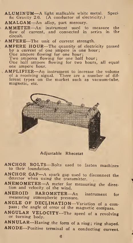
AMPLIFIER—An instrument to increase the volume of a receiving signal. There are a number of dif¬ ferent types on the market such as vacuum-tube, magnetic, etc.
Adjustable Rheostat
ANCHOR BOLTS—Bolts used to fasten machines to their foundation.
ANCHOR GAP—A spark gap used to disconnect the detector when using the transmitter.
ANEMOMETER—A meter for measuring the direc¬ tion and velocity of the wind.
ANEROID BAROMETER—An instrument for measuring atmospheric pressure.
ANGLE OF DECLINATION—Variation of a com¬ pass; the angle of error of the magnetic compass.
ANGULAR VELOCITY—The speed of a revolving or turning body.
ANNULAR—Having the form of a ring; ring shaped.
ANODE—Positive terminal of a conducting current.
6

\ ANTENNA—A receiving aerial.
ANTI-FRICTION METAL—A tin, lead alloy like Babbit Metal.
ANTI-INDUCTION CONDUCTOR—A conductor so made that it avoids induction effects.
ANTI-SPARK DISCS—Discs made of Ebonite used to assist in preventing sparking on Bradfield tube.
APERIODIC—Not tuned.
APERATURE—An opening of any description in a partition.
ARC—The arc between the two carbon electrodes slightly separated.
ARC RECTIFIER—An apparatus used to change Alternating Current to Direct Current.
AREOMETER—An instrument for finding the specific gravity of a fluid.
ARMATURE—A collection of pieces of iron designed to be acted on by a magnet; a part of a generator.
ARMATURE BORE-—The space within which the the armature revolves.
ARMATURE COILS—The wires wound on the core of the armature.
ARMOR CABLE—Wire enclosed in a metal pro¬ tective covering.
ARTIFICIAL MAGNET—A piece of iron or steel that has been magnetized.
ASBESTOS—A fibrous variety of ferro-magnesium silicate. A non conductor of heat, and fireproof.
ASBESTOS COVERED WIRE—A cable of very fine strands of copper wire all twisted together and covered with an asbestos covering.
ATMOSPHERE—Air, a mixture of. gases.
' ATOM—The smallest division of a substance..
ATTENUATE—To make thin; to lessen the force of.
AUDION—A relay operated by electrostatic control of currents flowing across a gaseous medium; con¬ sists of a heated filament, a grid electrode and a metal plate all enclosed in a highly evacuated bulb.
ANDIOMETER—A meter for measuring the strength of incoming signals.
AURORIA BOREALIS—A luminous display and electrical phenomenon seen in the heavens in the northern hemisphere.
AUTO M ATI C—Self-acting.
AUTOMATIC TRANSMITTER —A transmitter operated by running a paper tape between small metal wheels.
7

' AUTOMATIC TRANSFORMER—A transformer provided with one coil instead of two, part of the coil being traversed by the primary, and part by the secondary current.
V AUXILIARY ANODE—The third element of the amplifier.
A. W. G.—American Wire Gauge.
B. A.—British Association.
B. and S. W. G.—Brown and Sharpe Wire Gauge.
Adjustable Load Coil
B. W. G.—Birmingham Wire Gauge.
B. X.—Metal tubing cantaining twin conductors each insulated from the other and both wires wrapped so as to completely fill the tubing.
BABBIT METAL—An anti-friction metal.
BALANCE, ELECTRIC—Wheatstone bridge.
BALANCING SET—A dynamo used in a three wire system to balance the electromotive force.
BALANCE WHEEL—A fly wheel; a wheel added to machines to prevent too sudden variations in speed.
BALL AND SOCKET JOINT—A joint in which spherical object is placed within a socket made to fit it.
BALL BEARING—A bearing whose journal works upon a number of metal balls and thus reduces friction.
BALLISTICS—The science dealing with the velocity, path and impact of projectiles.
BALLISTIC GALVANOMETER—A galvanometer used for measuring short duration currents. Used for measuring a condenser discharge.
BAR MAGNET—A straight bar of steel with both ends magnetized.
BAROMETER—A meter for measuring the pressure of the atmosphere.
8

BARS, COMMUTATOR—The bars of copper or bronze, making up the segments of a commutator of a dynamo or motor.
BARRETTER—A thermal detector.
BASE PLATE—The plate used as a foundation.
\ BATTERY—A combination of elements for the pro- duction of storage of electrical energy.
BATTERY, DRY—An open circuit battery containing solified zinc oxychloride of gelatinous silica.
BATTERY GAUGE—A small galvanometer for test¬ ing batteries and connections.
BEARING—The support on which the moving part of a machine rests.
BEARING SURFACE—The surface of bearing part# which are in mutual contact.
BEAUMES HYDROMETER—A hydrometer named after its maker; used to measure liquids lighter than water.
BED PIECE—The frame carying a dynamo or motor
BERNE BUREAU—Bureau of the International Telegraph Union at Berne, Switzerland.
Basketball Vario-Coupler
BICHROMATE CELL—Two carbon plates immersed in a solution of sulphuric acid, bichromate of potasfe and water.
BIFURCATION—Spreading into two branches.
BILLI CONDENSER—A variable tubular condenser.
BINDING POSTS—Metal fixtures fitted to receive the ends of wires and thus make electrical contact
9

BISMUTH—One of the elements that is a conductor of electricity.
BOARD OF TRADE UNIT—An English standard, 1,000 watt hours, equal to one and one-third horse power; written B. O. T.
BLIND FLANGE—A plate used to cover an orifice.
BLUE STONE—Crystallized copper sulphate.
BOLOMETER—An apparatus similar to Wheatstone Bridge.
BORE—The interior diameter of a cylinder.
BOOSTER—A dynamo used to raise the pressure of another dynamo.
BRADFIELD INSULATOR—A leading-in insula¬ tor: an ebonite tube fittted with ebonite spark discs made to prevent rain running down and making a ground connection.
BRASS—An alloy of seven parts copper and three parts zinc.
BRAZING^—The process of joining metals together.
BRAZING METAL—An alloy of tin and zinc.
BREAKER—A switch or other device for opening a circuit.
BRONZE—An alloy of copper, tin and lead.
Variometer Units 1
BROWN AND SHARPE GAUGE—A wire gauge of American standard.
X BRUSH—A rod of carbon held in a holder and pressed against the commutator.
s BRUSH HOLDER—An adjustable clamp into which the brushes are fixed and then held against the commutator.
BRUSH, WIRE—A brush made of rolled wire gauze.
B. T. U.—British Thermal Unit.
10

BUFFING WHEEL—A wheel covered with leather and mounted so it can be rotated; used for polish¬ ing.
BUS BAR—A heavy copper conductor used on dis¬ tribution boards.
B. W. G.—Birmingham Wire Gauge. CABLE—A heavy electrical conductor highly in¬
sulated.
Showing Correct Method of Setting Brushes
CALL BELL—A bell used to attract the attention of the person called.
CAM—A revolving disc rotated on a shaft or spindle and shaped to give a variable motion to a driven element.
CAM FRICTION—The friction between the cam and the element it actuates.
CANADA BALSAM—A gum used in cementing lenses. Obtained from balsam fir.
CAPACITY—The extent of space; power of contain¬ ing.
CARRYING CAPACITY—The capacity of an elec¬ trical conductor to carry current without over¬ heating.
CARBON—One of the elements; exists in three forms,—charcoal, graphite and diamond. It is used as an electrical conductor, for arc Lamps and in¬ candescent lamp filaments. The carbons used for arc lamps generally have a core of soft powdered carbon.
11

CARBORUNDUM—An artificial silicate of carbon produced under very high temperature; often used as crystal detector.
CARTRIDGE FUSE—A safety device; fuse wire en¬ closed in a cardboard tube with metal ends.
CASCADE—A number of Leyden jars connected in series.
CATHODE—The terminal of an electrical circuit.
CAT WHISKER—The fine wire used on a crystal detector.
CENTIGRADE—A thermometer scale; freezing point 0° ; boiling point 100°.
CENTIMETER—Unit of length, 0.3937 inch.
CENTRAL STATION—A point from which current is sent out.
CENTRIFUGAL FORCE—The force which draws a body constrained to move in a circular path, away from the centre of rotation.
Flexible Armored Cable. Twin Conductors
CHARACTERISTICS OF SOUND—A, pitch; b, loudness; c, quality.
CHARGE—A quantity of electricity at rest, measured by units of quantity such as the coulomb.
CHECK UNIT—Generally called lock nut, a nut placed over another nut on the same bolt to lock the main nut in place.
CHLORIDE—A non-inflammable gas, Atomic weight 34.90. Specific Gravity 1.4.
CHOKE COILS—Coils of wire wound on an iron core sometimes called induction coils.
CHRONOSCOPE—An instrument for measuring very short intervals of time.
CIRCUIT—The path through which the current flows.
CIRCUIT-BREAKER, AUTOMATIC —A device a c.rcuit.
CIRCUIT, CLOSED—A circuit closed so as to give the current a continuous path.
CIRCUIT, OPEN—A circuit with its continuity broken, as by the opening of a switch.
12

v CIRCUIT-BREAKER, AUTOMATIC—A device that automatically breaks the circuit in case of overload.
s CIRCUIT, GROUNDED—A circuit where the re¬ turn wire is done away with so that the earth completes the circuit, as in wireless work.
CIRCULAR MIL—Unit of area, the area of a circle whose diameter is one mil.
CLEAT—A wood, porcelain or composition support for wires.
CLOCKWISE—A machine or other device that runs in a right hand direction; that travels as do the hands of a clock.
CLOTH WHEEL—A polishing wheel.
CLUTCH—A device for engaging or disengaging two pieces of shafting.
CODE, CIPHER—A code of prearranged words, letters or signs.
CODE, TELEGRAPHIC—An alphabet made up of dots and dashes.
^ COIL—A series of rings or turns of wire,
x COIL, INDUCTION—Built the same as a trans¬ former; has a laminated iron core and a primary and secondary coil.
COIL, RESISTANCE—A coil of some poor conduct¬ ing metal wire such as German silver. Used to offer resistance to the flow of current. A rheostat.
COINCIDE—Two or more articles that occupy the same place in space.
COLLET—A metal ring used to retain metallic pack¬ ing in a stuffing box.
COMMUTATOR—That part of a dynamo which changes the direction of the current.
COMPASS, RADIO—An apparatus used to find the location of a radio transmitting or broadcasting station.
COMPOUND—A mixture of two or more elements.
COMPOUND WOUND GENERATOR—A dyilfomo giving a constant electromotive force, on account of having its field magnet winding partly in shunt with current generated.
COUNTER CLOCK WISE—A machine that runs from right to left, the opposite direction to the hands of a clock.
\ CONDENSER—An appliance for storing up electrical energy, made of a number of thin sheets of tin foil laid on top of each other and separated from each other by an insulator. Condensers in multiple will increase the total capacity. Condensers in series will decrease total capacity.
13

CONDENSER, ADJUSTABLE—A condenser, part of which may be cut in or out of the circuit, thus varying its capacity.
CONDUCTANCE—The conducting property of any material.
CONDUCTOR—Anything that will permit the pas¬ sage of electricity—a wire.
Plug Fuse
CONDUCTIVITY—The reciprocal of the ohm. Unit is the Mho, (Ohm written backwards).
\ CONDUIT—A metal pipe through which electrical conductors are run.
CONTACT, ELECTRIC—A contact between two conductors giving a continuous path for the current.
CONTACT BREAKER—Any appliance for quickly opening or closing a circuit.
CONSTANT LOAD—A load whose pressure is steady and invariable.
CONTINUOUS—Uninterrupted, without break or in¬ terruption.
' CONTINUOUS CURRENT—Direct current. A current that always runs in the same direction. The opposite to alternating current.
CONTINUOUS WAVES—Waves whose amplitude are constant. Waves produced by frequency multi¬ plying transformers.
CONVERTER—An electric machine or apparatus for changing the potential difference of an electrical current.
COPPER—A metal; one of the elements; a good conductor of electricity.
CORE—The iron centre of a transformer, on which the primary and secondary coils are wound.
CORE DISCS—Thin metal discs used in building up armature cores, etc.
COTTER PIN—A headless split pin.
COUPLING WAVES—The two waves produced by coupling the oscillating circuits.
14

CORROSION—Chemical action which causes destruc tion of metals, usually by oxidation or rusting.
\ CORRUGATED—Formed with a surface consisting of alternate valleys and ridges.
\COULOMB —The practical unit of quantity of elec¬ tricity. It is the quantity passed by a current of one ampere intensity in one second.
\ COUPLING—The connection of two oscillating cir¬ cuits.
CRATER—The depression that forms in the positive carbon of a voltaic arc.
C. P.—Abbreviation for Candle Power.
CRYTAL DETECTOR—A detector using a crystal and thin metal wire to rectify a number of oscilla¬ tions.
CURRENT—A current of electricity is supposed to flow from the positive pole of a generator, through the various appliances in the circuit and back to the generator through the negative pole. The unit of current strength is the ampere.
Condenser
CURRENT, DIRECT—A current that always flows in the same direction. The opposite to Alternating Current. «
CURRENT, ALTERNATING—A current that is continually changing both its strength and direction. A current that changes its flow of direction so many times a second according to the construction of the alternator. These changes are called cycles.
CURRENT FREQUENCY—The number of times alternating current changes its flow of direction in a second. These changes are called cycles.
15
CURRENT, INDUCED—A current produced in a conductor by induction.
CURRENT, NEGATIVE—The current which deflects the needle to the left in a single needle telegraph system.
CURRENT, POSITIVE—The current which deflects the needle to the right in a single needle telegraph system.
CURRENT REVERSER—Some appliance, generally a switch for changing the direction of a current in a conductor.
CUT-OUT—Either a fuse or a magnetic control ar¬ ranged to open a circuit should the circuit be over¬ loaded.
CURRENT, SECONDARY—The current induced in the secondary coil of a transformer or induction coil.
CYCLE—A term given to the alternation of an alter¬ nating current circuit.
DASH COIL—An induction coil for jump spark ignition.
DAMPING—The weakening of amplitude in a train of electro magnetic waves owing to resistance and radiation from an oscillating circuit.
D. C.—Direct Current, (See “Current, Direct.”)
DEAD BEAT—Where the moving indicator of measur¬ ing instruments comes to a reading quickly, with¬ out the indicator oscillating.
DELTA GROUPING—A way of connecting up three phase windings in the form of a triangle.
DETECTOR—An apparatus that changes tlte oscilla¬ tions received by the aerial into audible sounds.
DETERIORATION—The state of growing worse.
DEVIATION—Divergence from a course.
DIAPHRAGM—A thin iron disc in the telephone receivers which is thrown into motion by electric impulses _ and changes the vibrations to audible sounds.
DIELECTRIC—A non-conductor of electricty.
DIFFRACTION—The bending of electro magnetic waves around the earth’s curvature.
DIMMER—An adjustable choking coil used to regulate the intensity of electric incandescent lamps.
DIRECT. CURRENT—A current of uniform strength that always flows in the same direction.
DIRECTION The direction of an electric current ts supposed to be from the positive pole to the negative pole of the circuit.
16

\ DIRECT COUPLING—A coupling where the in¬ ductance coils of botn currents are directly con¬ nected.
DIRECTION FINDER—See Radio Compass.
DIRECTIVE AERIAL—See Bellini Aerial.
DIRECT LOOSE COUPLING—A coupling where two .inductance coils, though directly connected, are at a distance from each other, or a coupling where only a few turns are common to both circuits.
DIRECT TIGHT COUPLING—A coupling where one circuit has its inductance formed by tapping off a number of turns from the coil actually em¬ ployed as inductance in the other circuit. Also called Direct Close Coupling.
Motor Generator
DISC CONDENSER—A variable condenser with its two sets of plates composed of semi-circular inter- leafing metal vanes, separated by insulating discs or air; the whole being mounted in a circular case, one set of vanes is fixed, the other mounted on an insulated spindle is capable of being turned through an angle of ISO degrees, thereby permitting of any desired amount of interleafirig of vanes; thus regu¬ lating the amount of capacity.
DISCHARGE—To dissipate electric energy from a condenser or battery.
DISTANCE SPARKING—The distance between elec¬ trodes which a spark from some source will jump.
DISTRIBUTION BOX—A metal box or cabinet containing a distribution panel together with fuses, switches, etc.
DOUBLE POLE SWITCH—A switch with two knife like blades, able to break both the positive and negative wires of a circuit.
DOWNLEAD—The wire connecting the aerial to the instruments.
17

DRY CELL—An enclosed battery used for open circuit work.
DUPLEX—Twofold, working two ways.
DYNAMICS—The mechanics of moving forces or motion, the reverse of static.
DYNAMO—A machine used to convert mechanical energy into electrical energy.
DYNOMETER—A meter for measuring mechanical force.
DYNE—Unit of force.
EARTH—Generally refers to a connection to the earth. An accidental grounding of a conductor.
EBONITE—Vulcanized India rubber; a non-conduc¬ tor of heat and electricity.
ECONOMIZER—A step-down transformer.
EFFICIENCY, MECHANICAL—The rate between the work performed and the energy expended by the machine in performing it.
Copper Wire Measuring Gauge
ELECTRICITY—An unknown power; a powerful physical agent which manifests itself mainly by at¬ traction and repulsion; also by luminous and heat¬ ing effects, by violent commotions, by chemical decompositions and many other phenomena. The word was first used by Dr. Gilbert in England dur¬ ing the Sixteenth Century.
ELECTRICS—Certain substances’ can be electrified by friction.
18

ELECTRODE—The terminal of an open electric v circuit.
ELECTRODYNAMICS—Electricity in motion.
ELECTROLYSIS—The breaking up of a compound into its elements by the use of an electric current.
ELECTRIC HORSE POWER—746 watts are equal to one unit of Electric Horse Power.
ELECTROLYTIC DETECTOR—A fine wire making contact with an electric light.
Vario-Coupler
ELECTRO MAGNET—A mass of iron magnetized by winding around it several coils of copper wire. The softer the iron the more easy it is to magnetize. Hard metals retain their magnetism longer.
ELECTRO MOTIVE FORCE—Another term foj electric pressure or voltage.
ELECTROSCOPE—Apparatus for detecting static charges of current.
' ELEMENT—There are ' about seventy-five known elements. Is an original form of matter that can¬ not be divided into constituents by any process.
EMBOSSER, TELEGRAPH—A receiver which em bosses telegraphic paper tape.
EMERGENCY APPARATUS—A second generator set that can be used in case of trouble.
EMERY WHEEL—A machine used for grinding.
E. M. F.—Electro Motive Force. Voltage. Pressure.
ENERGY—Capacity of acting; energy may be mechanical, electrical, chemical, physical, etc. Unit of energy is the ERG.
ENERGY, ELECTRIC—Unit is the volt coulomb or volt ampere.
EQUIDISTANT—Placed at equal distance from the same point.
EQUIVALENT, ELECTRO - CHEMICAL — T h e weight of a substance set free by one coulomb of electricity.
19

SRG.—The unit of work. The amount of energy expended in moving a body through one centimeter against a resistance of one dyne.
y ETHER—A name given by Huygens to the medium that fills all space and matter.
EXCITER—A dynamo used to excite the fields of a generator.
FAHRENHEIT—A thermometer scale. Freezing point is 32°. Boiling point, 212°.
FATHOM—A measure of length; six feet.
FARAD—Practical unit of capacity.
FEEBLY DAMPTED—A train of oscillations with many complete oscillatory motions.
FEEDER—A main wire or set of wires.
FEEDER, POSITIVE—-The wire connected to the positive pole of a generator.
FEEDER, NEGATIVE—The wire connected to the negative pole of a generator.
FEEDER, NEUTRAL—The wire connected 'to the middle or neutral point in a three-wire systefri. The wire common to both generators.
FIELD MAGNETS—Electric magnets that produce the magnetic field in which the armature of a gen¬ erator rotates.
FIELD REGULATOR—A variable resistance.
FLATS—Commutator segments worn to a lower level than other segments.
FLAT TUNING—The considerable adjusting of tun¬ ing without altering the strength of the signals.
FLUX—A compound used in soldering.
FOOT POUND—The resistance equal to one poum moved upwards one foot.
FORCE—May be defined as the rate of change of momentum.
FREAK—The increasing or decreasing of range of signals that periodically happens to a receiving set.
FREQUENCIES, RADIO—Radio frequencies are very high, sometimes as high as l,oOO,OUO cycles per second.
\ FUNDAMENTAL WAVELENGTH—Ordinary wave¬ length of a circuit.
20

FUSE—A short length of fusable wire introduced into a circuit as a safety device.
FUSING POINT—The temperature at which metals melt and become liquid.
GALENA—A crystal sulphide of lead. When heated becomes lead sulphate. Used as a thermo-electric detector.
GALVANIZED IRON—Iron with a coating of zinc to prevent rusting.
\ GALVANOMETER—An instrument for measuring current strength and direction of current in a circuit.
GAP—An opening by breaking or parting.
GAP MICROMETER—A gap to protect apparatus from overloads.
GASKET—A ring or washer used for packing or insulating.
GAUGE—An instrument to measure size or capacity.
GAUZE WIRE—A pliable wire cloth made of very fine .strands of wire.
GEISSLER TUBE—A vacuum tube having its elec¬ trodes in bulbs.
GENERATOR—An apparatus for maintaining an electric circuit.
GERMAN SILVER—Alloy of nickel and copper with a percentage of zinc. Used in resistance frames, rheostats, etc.
GOLD—One of the elements; a conductor of elec¬ tricity.
GONIOMETER—An instrument for measuring angles.
GRAM—The unit of weight. Equal to 15.43 grains.
GRAPHIC TELLURIUM—A crystal rectifier.
GRAPHITE—A soft form of carbon, used as a lubri¬ cant.
GRAVITY—The attracitve force of the earth.
% GRID.—A frame of wire gauze found between the plate and filament o/ a vacuum tube. Perforated
f lead plate used in storage batteries.
GRID LEAK—A form of rheostat to permit excess grid charges to escape to an external source.
GROUND—The contact of an electrical conductor with the ground or with some other conductor not in the circuit.
GROUND CLAMP—A strip of copper for making an easy and secure connection with a water pipe, etc.
GROUND WIRE—The wire leading from the aerial 'to the ground. The wire used as a return wire of the circuit in wireless work.
:i

GUN METAL—A compound of nine parts copper and one part tin.
GUTTA PERCHA—The hardened juice of the Isom andra Gutta, used as an insulator.
GUY ROPES—Ropes or wires used to steady the aerial supports.
HAND OR WING NUT—A nut with flanges allow¬ ing it to be tightened by hand.
HEAT—A physical kinetic form of energy.
HELIOGRAPH—A mirror for reflecting flashes of light, generally the Sun’s rays; used in signal work.
HELIX—A coil of wire.
HENRY—Unit of inductance.
HEITZIAN WAVES—Ether waves.
HIGH FREQUENCY—A current with a very great number of alternations per second.
HIGH FREQUENCY SLIDING INDUCTANCE— Two metal bars connected by a sliding brass clamp used for making final adjustment in closed oscilla¬ tory circuits.
HIGHLY DAMPED TRAIN—A train with few oscillations.
HONEY-COMB COIL—A tuning coil. A set of three coils—primary, secondary and tickler; the primary coil being placed between the other two.
HORSE POWER—A unit of rate of work. Equal to the raising of 3o,f)00 pounds one foot in one minute. Equal to 740 watts.
HORSE POWER HOUR—One horse power exerted for one hour.
Grid Leak
HORSE SHOE MAGNET—A steel bar shaped like a horse shoe with its ends magnetized.
HUMIDITY—The dampness in the atmosphere which varies with the temperature.
HYDROELECTRIC GENERATOR—A generator driven by a turbine.
HYDROMETER—An instrument used to test the specific gravity of a fluid. Used for testing the discharge of storage batteries.
HYPOTHESIS—Taken for granted. Assumed for the purpose of argument.
22

HYSTERESIS—A reluctance when a change of con¬ dition is taking place in a circuit.
IMPEDANCE—The total opposition of a circuit, due to reactance and resistance to a varying circuit.
IMPEDANCE COIL—Another name for induction coil, an iron core around which is wound a coil of wire.
Resistance Coils, Connected in Series With Each Other
INCANDESCENCE, ELECTRIC—The heating of a conductor to a white heat.
INCH—The twelfth part of a foot. A measure of length.
INCLINATION—A tendency from the true horizon¬ tal or vertical direction, as in the case of the compass needle.
INDUCTION COIL—A transformer; an apparatus for changing low voltage to high voltage.
INDUCTANCE—The induction of a current in a non¬ electrical body from an electrified or magnetized body, without metallic or electrical connection.
INDUCTOR—A step-down transformer.
INDUCTIVE COUPLING—The coupling of two oscillatory circuits by arranging the inductance coil of one circuit into the lines of force of the other circuit.
INDUCTIVE LOOSE COUPLING—A coupling without metallic contact and where the inductances are well apart.
23

INERTIA—Property of matter at rest.
INSULATOR—Any material that will not allow the passage of electricity through it, except under very great pressure.
INSULATING TAPE—A prepared tape to cover and insulate ends of wires when making joints, etc.
INTENSITY The strength of a current, expressed in amperes.
INTERMITTENT—Acting at intervals.
INTERSECTION—The place where two wires cross each other.
IRON A metal; one of the elements.
INTERFERENCE—-Where more than one set of electro magnetic waves arrive in such a manner as to nullify each other.
Variable Condenser
INVERTED "L” AERIAL—An aerial that is tapped at one end by the lead in wire.
JAMMING QRM. Interference from other stations. JIGGER—An oscillation transformer.
JOULES—Unit of electrical work. Volt coulomb.
JOr^?f?cAL_7vrhtt part of a shaft or spindle which rotates in the bearings.
KBY TRANSMITTER-An easily controlled switch wh’ch allows the operator to rapidly make and break the primary circuit.
KILOWATT One thousand watts. Written K. W.
24

KNIFE SWITCH—A switch with knife like blades, used on circuits carrying high amperage.
LAG SCREW—A wood screw with a square head.
LAMINATED—Made up of a number of fine sheets.
LATERAL FORCE—Force proceeding from the side.
LAW OF MAGNETISM,—Like poles repel one an¬ other. Unlike poles attract each other; positive pole attracts negative, etc.
LEADING-IN INSULATOR—An insulation tube used in the walls or roof through which the lead in wire from aerial runs.
LEAKAGE—A loss of current due to poor insula¬ tion or other causes.
Synchronous Gap Motor
LENZ LAW—An induced current always tends to stop the current which produces it.
LEYDEN JAR—A static condenser.
LIGHT—Light waves travel at the same rate of speed as electro magnetic waves; 186,000 miles per second. Light is merely ether vibrations.
LIGHTING ROD—A metal rod connected with the earth, used on buildings as a safety device.
LINES OF FORCE—Imaginary lines showing the direction of attraction and repulsion in a field of force.
LINK FUSES—A link of fusable metal, introduced into the circuit as a protective device.
25

LOADING COIL—A single slide, tuning coil.
LOCAL CURRENTS—Currents within the metal parts of a generator.
LOCK NUT—A nut placed over another nut on the same bolt to hold the original nut in place. A check nut.
LODESTONE—An iron ore which possess the prop¬ erties of a magnet. Also known as Magnetite.
LOG DECREMENT—The hyperbolic log of recipro¬ cal of the ratio of the first amplitude to second amplitude in a train of waves.
LOOSE COUPLING—A coupling without metallic contact or where the inductances are well apart.
LOST MOTION—The motion in a machine that produces no useful results.
LOW FREQUENCY—A current whose alternations are low per second.
AMMETER CONNECTED IN SERIES
\
LOOP AERIAL—A frame around which several turns of wire are wound.
LUBRICANT—Anything used to help diminish fric¬ tion between two or more working parts; like oil; graphite, etc.
LUGS—Metal wire terminals
MAGNET—A piece of iron or steel that has the property to attract or repel other pieces of metal.
MAGNET COIL—The coil over an iron core in an electric magnet.
MAGNETIC FIELD—The field or space over which the magnet exerts its influence.
MAGNETIC FLUX—The lines of force which flow from a magnet; magnetic induction.
MAGNETIC FORCE—Force at any point in a magnetic field.
MAGNET HORSESHOE—A bar of steel shaped like a horseshoe with both ends magnetized.
2 6

MAGNETIC LIMIT—The temperature beyond which a metal cannot be magnetized.
MAGNETIC SELF INDUCTION—A magnet tends to repel its own magnetism and weaken itself by self-induction.
MAGNETITE—A natural magnetic iron ore. Lode- stone.
MAGNETO—A small generator.
MAKE AND BREAK CURRENT—A current con¬ tinually broken and started again as is the action in an induction coil.
MALLEABLE—Capable of being worked into shape.
MANGANESE BRONZE—An alloy of copper, tin and ferromaganese ore.
MANGANESE STEEL—An alloy of steel and metal manganese.
MARCONI FILINGS COHERER—A glass tube containing fine metallic filings used as a detector.
MEGAPHONE—An instrument used to help make the voice audible at a distance.
MEGOHM—One million ohms.
Adjustable Filament Rheostat
MERCURY—A metallic element liquid at ordinary temperature; also known as quicksilver.
METER VOLT—An instrument for measuring the pressure or voltage of a. circuit. Connected in mul- tiple on your line.
METER AMPERE—An instrument for measuring the
flow of current.
27

METER WATT—An instrument for measuring the wattage. Volts times amperes.
MHO—Unit of Conductivity. The word ohm spelled backwards.
MICA—A mineral more or less transparent and used as an insulator.
MICANITE—A manufactured insulator made of mica,
MICRO—One millionth.
MICROFARAD—Unit of capacity.
MICROHM—One millionth of an ohm.
MICROMETER—An instrument for measuring small distances like the thousandth or ten thousandth part of an inch.
MICROMETER SPARK GAP—An adjustable spark gap used in the aerial circuit.
MICROPHONE—An apparatus to magnify sound.
MIL CIRCULAR—A unit of area. The area of a circle whose diameter is one mil.
MIL FOOT—A unit of resistance. A wire one foot long with a diameter of one mil.
MILLIMETER—A unit of length. One thousandth part of a meter.
MINIMUM—The least quantity.
MOLECULE—The smallest part of an element that can exist alone.
MOLYBDENITE.—A sulphide of Molybdenum. Used as a detector.
MORSE RECEIVER—A receiver named after S. F. B. Morse.
MORSE INKER—An instrument that records the received message on a travelling paper tape.
MOSCISKI CONDENSER—A condenser in the form of a glass tube with a metal foil coating.
MOTOR—A machine to convert electrical energy into mechanical energy.
MOTOR GENERATOR—A combined motor and generator; a generator driven by a motor.
MOTOR SERIES—A motor whose armature wind¬ ings and field windings are in series.
MULTIPLE—Multiple connection is that in which each lamp draws its supply direct from the mains and is not depending on any other lamp or set of lamps for its supply. Lamps in parallel with each other. The opposite to series.
\ MUTUAL INDUCTION—The introduction of an electrical pressure in a circuit, by another circuit not directly connected to it.
28

NATURAL CURRENTS—Earth currents.
NATURAL WAVELENGTH—The natural length of wave produced by the aerial’s own capacity and inductance.
NEGATIVE—The opposite to positive. The pole to which the current seems to flow.
NEGATIVE CHARGE—One of the two electric charges, the opposite to positive.
NEUTRAL WIRE—The middle wire of a three wire system. t The wire that is common to both dynamos.
NICKEL SILVER—An alloy of nickel, copper and zinc. German silver used in making resistance coils.
Basketball Variometer
NICKEL STEEL—Steel with the addition of a small percentage of nickel.
NON-CONDUCTOR—Any material that will nor 'conduct electricity.
NON-INDUCTIVE CIRCUIT—A circuit possess ing a very small inductance.
NOTCH WIRE GAUGE—A gauge with notches foT measuring wire.
OHM.—Unit of electrical resistance. The resistance offered by a column of pure mercury, 106.3 centi¬ meters in length by one square millimeter in cross section at a temperature of zero centigrade.
OHM’S LAW—The fundamental principle on which all electrical mathematics are worked. The current in amperes is equal to the voltage divided by the resistance in ohms. The resistance is equal to the voltage divided by the current in amperes. The voltage is equal to the resistance in ohms times current in amperes. Thus with two known quan¬ tities you can always find the third unknown.
29

OHMIC RESISTANCE—True resistance.
OSCILLATING CURRENT—An alternating current of high frequency.
OSCILLATOR HERTZIAN—A device for produc¬ ing oscillations.
OSCILLATORY INDUCTION—Induction produced by action of an oscillatory discharge.
PAPER CONDENSER—A condenser made with tin foil and paraffin paper.
PARTITION INSULATOR—A leading-in insulator.
PERIOD—Time required to produce and complete one wave: time required to complete one cycle of an alternating current circuit.
PERIPHERY—The circumference of a circle.
Radiotron Tube Socket
PERMANENT MAGNET—A magnet that will re¬ tain its magnetism away from the source of magnet¬ ism.
PHENOMENON—An unusual occurrence.
PHONETRON—A trade name for a type of amplify¬ ing telephone receiver. Consists of an enclosed electro-magnetic solenoid producing an annular field in which an armature coil is suspended from the apex of a conical diaphragm. The magnet requires a current of amperes at a pressure of 6 volts.
PHOSPHOR BRONZE—A very hard alloy of copper, tin and phosphorus.
PLUNGER—A movable core used with a solenoid to be drawn in an oil bath when the coil is excited.
POLARIZATION—The changing of a voltaic cell by depriving it of its proper pressure.
POLARITY—Pertaining to the poles of a circuit; the positive and negative.
POLYPHASE—More than one phase. Multiphase.
30

POSITIVE POLE—The pole from which the cur¬ rent is supposed to start on its journey around the circuit.
POTENTIAL—The pressure of an electric charge.
POTENTIOMETER—An arrangement for determ¬ ining potential difference.
POUNDAL—British unit of force.
POWER—Activity; rate of doing work.
PRIMARY COIL—The coil of a transformer that is connected to the source of supply.
PRIMARY COLORS—Red, yellow, blue.
PRIMARY POWERS—Water power; wind power; tide power; power of combustion; power of vital action.
PRIMARY TUNING INDUCTANCE—A variable inductance in the primary closed oscillatory circuit.
PROTECTIVE ROD—A carbon rod of high resist¬ ance connected into the circuit as a safety measure.
PROPAGATION—The travelling of electro magnetic waves over the earth’s surface.
PYROMETER—A meter for measuring excessive heat.
QUADRANT—A quarter of a circle; an angle of 90 degrees.
QUARTZ—A hard rock of native silica.
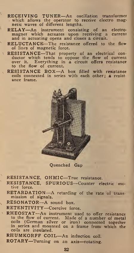
QUENCHED SPARK—A spark gap made of a series of metal plates insulated from each other.
QUICKSILVER—Mercury; a liquid metal.
RADIAL—Spreading from a centre.
RADIATION — The transmission of ether waves through space.
RADIATING CIRCUIT—The aerial circuit.
RADIO TELEPHONY—Transmission of speech by electro magnetic waves.
REACTION—Inverse action.
REACTANCE—The opposition offered to the flow of current by back electro motive force, etc.
REACTANCE COIL—An adjustable iron core around which is wound a coil of wire.
RECTIFIER—An apparatus for changing alternating current to direct current.
REFRACTION—The change in direction or bending of the electro magnetic waves.
REGENERATIVE CIRCUIT—A reactionary circuit.
RECEIVING DETECTOR—A device to change the characteristics of incoming oscillations so as to make them audible.
31
RECEIVING TUNER—An oscillation transformer which allows the operator to receive electro mag¬ netic waves of different lengths.
RELAY—An instrument consisting of an electro¬ magnet which actuates upon receiving a current and in actuating opens and closes a circuit.
RELUCTANCE—The resistance offered to the flow of lines of magnetic force.
RESISTANCE—That property of an electrical con¬ ductor which tends to oppose the flow of current over it. Everything in a circuit offers resistance to the flow of current.
RESISTANCE BOX—A box filled with resistance coils connected in series with each other; a resist¬ ance frame.
Quenched Gap
RESISTANCE, OHMIC—True resistance.
RESISTANCE, SPURIOUS—Counter electric mo¬ tive force.
RETARDATION—A retarding of the rate of trans mission of signals.
RESONATOR—A sound box.
RETENTIVITY—Coercive force.
RHEOSTAT—An instrument used to offer resistance to the flow of current. Made of a number of metal coils (German silver or iron) connected together in series and mounted on a frame from which the coils are insulated.
RHUMKORFF COIL—An induction coil.
ROTARY—Turning on an axis—rotating.
82

RUBBER COVERED WIRE—A cable either solid or stranded with a rubber covering and an outer protective covering of cotton braid.
SAL AMMONIAC—Ammonium chloride.
V SECONDARY COIL—The coil of a transformer into which the current is induced.
\ SERIES—An electrical connection where lamps are connected so that they depend one on the other for supply, the current passing through each lamp suc¬ cessively. The opposite to multiple.
\
\
SET COLLAR—A ring used on a shaft or spindle to prevent end play,
SEXTANT—An instrument used on board ship to measure angles.
SHEET METAL GAUGE—A gauge to measure the thickness of metals.
SHELLAC—A gum gathered from trees in India used in radio and electrical work in the form of a varnish. An excellent insulator.
SHORT CIRCUIT—Two wires of opposite polarity coming in contact with one another without any controlling device.
SHUNT—A shunt for the receiving relay consisting of the coils of an electro magnet.
SHUNT WINDING—A system of winding where the armature winding is in parallel with the field winding.
SILICON—A mineral. Used as a detector.
SIXTY CYCLE A. C.—This is when the current changes its flow of direction sixty times a second. This frequency is used a great deal for lighting and power purposes.
SINGLE PHASE—Using only two wires and one electromotive force; sometimes called monophase.
SLIDING FRICTION—The friction that exists be¬ tween moving parts in sliding contact with each other.
SLIP RINGS—Two rings on an alternator that take the place of a commutator on a direct current dynamo.
SOLENOID—An electro magnet without the iron core.
SPARK COIL—An insulated wire wound around an iron core, used for producing a spark from a source of low pressure.
SPARK GAP—The space between the ends of an electric resonator across which the spark jumps.
33

V SPECIFIC GRAVITY—The density of a solution against that of another, using water as a standard.
SPECIFIC RESISTANCE—Resistance of any ma¬ terial having a cube of one centimeter.
SPIRAL WINDING—The system of winding used on a ring armature.
STAGE CABLE—A cable containing twin con¬ ductors each insulated from the other and the whole covered with a composition covering.
STAND-BY—A position of tuning, allowing the re ception of waves of various lengths. QRX.
RHEOSTAT RHEOSTAT
® Q ®
\ o C
\ O Ok
\
rheostats in series
STANDARD CELL—The Weston Cell is now used as the standard.
STARTING BOX—An adjustable resistance to regu late the flow of current when starting up the motor.
STATIC—Atmospheric disturbance.
STATIC CHARGE—An electric charge at rest.
STATIC LEAK—A coil of wire used in the aerial circuit of tuner to allow atmospherics to leak to earth.
STATIC TRANSFORMER—A transformer withoui moving parts.
STATOR—The stationary part of an induction motor or generator.
STEEL—Iron hardened by the addition of carbon and managanese.
STEP DOWN TRANSFORMER—A transformer that steps down the voltage and raises the amper- s&ejrjhns a greater number of turns of wire in prim¬ ary, than in secondary.
STEP UP TRANSFORMER—A transformer that steps up the voltage and lowers the amperage; has a greater number of turns of wire in the secondary than in the primary.
34

STORAGE BATTERY—An accumulator. A number of cells for the storage of electricity.
STORAGE CAPACITY—The number of ampere hours that can be got from a storage battery.
SULPHATING—The formation of a lead sulphate in storage batteries. May be overcome by pro¬ longed charging.
SULPHURIC ACID—A compound of sulphur, hydro¬ gen and oxygen.
SWITCH—A device for opening or closing a circuit.
SWITCH BOARD—A board to which the mains are led connecting with bus bars, fuses and switches.
SWITCH, DOUBLE POLE—A heavy switch that disconnects or connects two leads simultaneously.
SWITCH, KNIFE—A switch with knife like blades used on circuits carrying high amperage.
SWITCH, SNAP—A small switch made to give a sharp break used on house lighting circuits, etc.
SWITCH, THREE WAY—A switch so constructed that by turning its handle connection can be made from one lead to either of two other leads and also so that connection can be completely cut off.
SYNCHRONOUS—Simultaneous; to correspond in time.
SYNCHRONOUS MOTOR—A motor which runs in synchronism with the alternating current supply.
c-\ s
\
V -V
rheostat
® V r
RHEOSTAT
qS_9l]
/ r _I_J L.___—--——--'
RHEOSTATS IN MULTIPLE
"T” AERIAL—An aerial where the horizontal span is tapped in the middle by the lead in wire; thus forming a letter T.
TELEFUNKEN—German name for radio telegraphy.
TERMINAL LUGS—Metal terminals for ends of wire used so that good and quick connection can be made.
TESLA COIL—An oscillating transformer.
THERM—A unit of heat.
35

THERMAL DETECTOR—A detector which acts by heat energy.
TOGGLE JOINT—An elbow joint.
THREE WIRE SYSTEM—A system of distribution of electrical current where three wires instead of two sets of two wires are used. The middle or neutral wire acts as a positive for the one side and of the system and as the negative for the other side. The advantage of the system is the saving of copper.
TICKLER COIL—A coil in the circuit of a vacuum tube receiver to transfer a part of the oscillating plate current energy into the grid circuit to enable the vacuum tube to generate oscillations of high frequency. It is coupled to the secondary of the oscillation circuit. An inductance coil.
TONE FREQUENCY—Spark frequency.
Wavemeter
TRANSFORMER—An apparatus used on an alter¬ nating current circuit to either raise or lower the voltage. Made of two coils of wire named the primary and the secondary coils and a laminated iron core. The coils are insulated from the core and from each other. The current enters the trans¬ former through the primary coil and sets up a magnetic flux around the core; the secondary coil cuts the lines of magnetic force and thus a new current is induced in the secondary.
36

TRANSFORMER COILS—The two coils in a trans¬ former ; primary and secondary.
TRANSFORMER CORE—A core made up of thin iron plates laid one on top of the other.
TRANSMITTER—An instrument used to produce sounds to be transmitted.
TRANSVERTER—A trade name for a motor gener¬ ator.
TUNING—The process of securing the maximum in¬ dication by adjusting the time period.
TWO PHASE—An alternating current system of electrical distribution making use of two currents of different phase. Can be arranged with either three or four wires.
UNIPOLAR DYNAMO—A dynamo where one part of the conductor slides around the magnet.
ULTRAUDION—An audion used in a circuit having a type of energy coupling so that a powerful relay action may be obtained. Its elements are connected in two circuits so arranged that the energy coupling may be obtained through a bridging condenser in its plate filament circuit.
VACUUM—A space destitute of all substance.
VACUUM TUBE—The name given to the highly exhausted glass tube containing three elements. Used for detector in radio work.
VARIO-COUPLER—A device for varying the in¬ ductance in a circuit. The primary and secondary coils are connected magnetically but not electrically.
VARIOMETER—A device for varying the induc¬ tance in a circuit. Made by connecting two in¬ ductances in series.
VARLEYS CONDENSER—A static condenser.
VELOCITY—The rate of motion of a body.
VIBRATION PERIOD—In electrical resonance the period of a vibration in an electrical circuit.
VALVE AMPLIFIER—Audion type vacuum tube containing three electrodes.
VALVE TUNER—A tuner used with a valve de¬ tector.
VARIABLE CONDENSER—A condenser which al¬ lows of easy and quick adjustment.
VOLTAGE—Electric motive force or pressure.
VOLTMETER—An instrument used to measure the pressure of a circuit.
VULCANITE—Vulcanized India rubber.
WATT—The practical unit of electrical power. Am¬ peres times voltage.
37

\ One WATT HOUR—Watts times length in hours. watt expended for one hour.
WATT MINUTE—One watt expended for one minute.
WATT SECOND—One watt expended for one second.
WAVE CHANGER—A transmitting switch to change from one wave length to another.
WAVES, ELECTRO-MAGNETIC—Ether waves due to electro magnetic disturbances.
WAVE LENGTH—The distance covered by a wave from the transmitting station before the next suc¬ cessive wave starts.
WAVE TRAIN FREQUENCY—The total number of waves being produced or received per second.
WAVE METER—An instrument to measure wave lengths.
WIRE GAUGE—A gauge for measuring the dia¬ meter of wires.
Centimeters to Inches
cm. inches
1 zz H 2 zz it 3 zz 1ft 4 zz 1ft 5 zz Hi 6 zz 2 x 7 zz 2H 8 zz 3ft 9 zz 3ft
10 zz 3 if 11 zz 4ft 12 zz 4 H 13 zz 5 'A 14 zz 5 y* 15 zz m 16 zz 6 ft 17 zz 6H 18 zz 7 ft 19 zz IVi 20 = 7^
The above values are correct to ft in.
Inches to Millimeters
Inches mm. cm.
ft zz 1,58 — 0,16
v% zz 3.17 zz 0,32 — G.35 zz 0,63
H — 9,5 zz 0,95 y2 — 12.7 zz 1,27 Vs zz 15,9 zz 1,59
H — 19 zz 1,9 — 0‘> 2 — 2,2
l — 25,4 — 2,54 2 zz 50.8 zz 5,08 3 zz 76.2 zz 7,6 4 zz 101,6 zz 10,1 5 — 127 zz 12,7 6 — 152 — 15,2 7 — 177 — 17.7 8 — 203 — 20.3 9 — 229 zz 22.9
10 — 254 zz 25,4 11 — 280 zz 2S 12 304 = 30,4
The above values are correct to Yi mm.
38

U. S. RADIO LAWS AND
REGULATIONS
The owner of an amateur radio transmit- ;ing station must obtain a station license be-
| fore it can be operated if the signals radiated ! herefrom can be heard in another state; and [ also if such a station is of sufficient power i as to cause interference with neighboring I licensed stations in the receipt of signals from ! transmitting stations outside the state. These I regulations cover the operation of radio-tele¬ phone stations as well as radio-telegraph
I stations.
Station licenses can be issued only to citizens of the United States, its territories and dependencies.
Transmitting stations must be operated un¬ der the supervision of a person holding an Operator's License and the party in whose name the station is licensed is responsible for its activities.
The Government licenses granted for ama¬ teur stations are divided into three classes as follows:
Special Amateur Stations known as the “Zr class of stations are usually permitted to trans¬ mit on wave lengths up to approximately 375 meters.
General Amateur Stations which are per¬ mitted to use a power input of 1 kilowatt and which cannot use a wave length in excess of 200 meters.
Restricted Amateur Stations are those lo¬ cated within five nautical miles of Naval radio stations, and are restricted to ^ kilowatt in-
39

put. These stations also cannot transmit on wave lengths in excess of 200 meters.
Experimental stations, known as the “X” class, and school and university radio stations, known as the “Y” class, are usually allowed greater power and also allowed the use of longer wave lengths at the discretion of the Department of Commerce.
All stations are required to use the minimum amount of power necessary to carry on suc¬ cessful communication. This means that while an amateur station is permitted to use, when the circumstances require, an input of 1 kilo^ watt, this input should be reduced or othj means provided for lowering the antenj ' energy when communicating with near-by st tions in which case full power is not require
Malicious or wilful interference on the pa $ of any radio station, or the transmission i any false or fraudulent distress signal or csA is prohibited. Severe penalties are provide for violation of these provisions.
Special amateur stations may be licensed I the discretion of the Secretary of Commeri to use a longer wave length and higher powC than general amateur stations. Applicants fer special amateur station licenses must have ha two years’ experience in actual radio con! munication. A special license will then t granted by the Secretary of Commerce on! if some substantial benefit to the science ci radio communication or to commerce seen* probable. Special amateur station licenses art] not issued where individual amusement is th chief reason for which the application is madtj Special amateur stations located on or nea the sea coast must be operated by a perso holding a commercial license. Amateur statio licenses are issued to clubs if they are inj corporated, or if any member holding an amal fa,it- Anprofnr’c lirpncp will nerent the reSDOn teur operator’s license will accept the respon sibility for the operation of the apparatus.
40

Applications for operator's and station licenses of all classes should be addressed to the Radio Inspector of the district in which the applicant or station is located. Radio Inspectors' offices are located at the following places:
First District.Boston, Mass.
Second District.New York City.
Third District.Baltimore, Md.
Fourth District..Norfolk, Va.
Fifth District..New Orleans, La.
Sixth District..San Francisco, Cal.
Seventh District.Seattle, Wash.
Eighth District.Detroit, Mich.
Ninth District..Chicago, Ill.
No license is required for the operation of a receiving station, but all persons are required by law to maintain secrecy in regard to any messages which may be overheard.
There is no fee or charge for either an operator’s license or a station license.
Variable Condenser
41

Broadcasting Stations
Where Located State
Camden . N. J. Newark . N. J. N ewark . N. J. Jersey City . N. J. Jersey City . N. J. New York .. N. Y. New York .. N. Y. New York .. N. Y. New Haven . Conn. Hartford . ... Conn. Springfield . . Mass. Medford ** » Hillside . Mass. Worcester .. . Mass. Washington . Washington .
D. C. D. C.
Washington . D. C. Washington . D. C. Philadelphia . Pa- Pittsburgh .. Pa. Pittsburgh .. Pa.
Indianapolis , Ind.
Toledo. Ohio Cincinnati .. Ohio Detroit . Mich.
Chicago . Ill.
Madison .... . Wis. Omaha . Neb.
Minneapolis , , Minn.
Kansas City Mo. Lincoln ..... Neb. Denver .... Col. Denver .... Col. Los Altos . . Cal. Pasadena ... Cal. Los Angeles Cal. Los Angeles Cal. Los Angeles Cal. Hollywood . . Cal. Oakland ... . Cal. Oakland ... . Cal. Sacramento . Cal. (San Francisco Cal. San Francisco Cal. San Francisco Cal. San Jose .. . Cal. Stockton ... . Call. Stockton ... . Cal. Sunnyvale .. . Cal. Seattle . . Wash
Station Call Operated by
W P R Federal Institute of Radio WOR L. Bamberger & Co. W J Z Westinghouse Co.
W N O Jersey Journal 2AI Jersey Review
W J X De Forest Radio Co. WDT Shipowners Radio Service
WYCB Amateur Radio Reserve WCJ A. C. Gilbert Co.
W Q B C. D. Tuska Co. W B Z Westinghouse Co.
W G I Am. Radio Research Co. W C N Clark University W D N Church of the Covenant W D W Radio Construction Co. W J H White & Boyer Co. N O F Board of Health W I P Gimbel Bros.
K D K A WTestinghouse Co. W P B Newspaper Printing Co. WLK Hamilton Mfg. Co. D W Z Marshall Gerken Co.
W M H Precision Equipment Ca W B L Detroit News K Y W Westinghouse Co. W H A University of Wisconsin W O U R. B. Howell WLB University of Minnesota
9 Z A B Western Radio Co. 9 Y Y State University
9 Z A F Revnolds Radio Co. K O A Y. M. C. A. K L B Colin B. Kennedy Co. K L B J. J. Dunn & Co. K 0 L Arno A. Kluge K Y J Leo J. Meyberg Co. K Z C Western Radio Electric Co K G C Electric Lighting Co. K Z M Preston D. Allen K Z Y Atlantic & Pac. Radio Sup ZVQ J. C. Hobrecht KDN Leo J. Meyberg Co. KGB Edwin L. Lorden K Y Y Radio Telephone Shop
K Q W Charles D. Herrold K J Q C. O. Gould
K W G Portable Wireless Tel. Co K J J The Radio Shop
K F G N orthern Radio Electric Co.
42

Highpower Radio Stations
United States and Possessions
Location Call Wave Length
NSS 16900 Arlington, Va. NAA 6000 Raifanfv ri. z.. NBA 7000 Poston Mass.. NAB 5700
Cavite, P- I. NPO 12000 NAO 4700 NPA 7600
Great Pa Ices. NAJ 5700 Guam Marianna Islands. NPN 5000
NAW 4500 NAR 6500 wso 11500 NFF 13600
New Orleans, Pa. NAT 5500 Pearl Harbor Hawaii. NPM 11000
NPC 5250 NPL 13300 and 9800
San Francisco, Cal. NPG 8600 and 4800 NAU 5250 NDD 11600 and 9800 NWW 9200 NPU 6000 and 3000
Great Britain and Other Countries
Location
Barrington Passage, N. S..
Bermuda, W. I. Camarron, Wales. Christiana, Jamaica. Hong Kong, China. Horsea, England. Punta, Delgada, Azores. Singapore, Malay Peninsula.. St. Johns, Newfoundland. Eiffel Tower, Paris. Lyons, France. Nantes, France. Rome, Italy. Hanover (Eilvese), Germany. Nauen, Germany. Funabashi, Japan. Stavanger, Norway.... Java, Dutch East Indies.
Call Wave Length
VCU 5000 BZR 5000 MUU 14000 BZQ 5000 BXY 5000 BYC 4500 BWP 2000 VPW 3400 BZM 5000 FL 10000 YN 15500 VAUA 9000 and 11000 IDO 11000 OUI 15000 POZ 12600 JJC 7700 LCM 9500 and 12000
PMM-PMX 6100
43

Miscellaneous Damped Wave Stations
Location Call Wave Length
Arlington, Va., U. S.. . NAA NJK VMG MFT GB VKT MPD VJZ
2500 1800 2000 6000 7500 2200 2800 2900 1800 6500 5500 4000
5000 and 7000
New Orleans, La., U.S.A., “WNU”. Apia, Samoa. Clifden, Ireland.. Glace Bay, N. S... Nauru, Pacific Ocean. Poldhu, Ireland. Rabaul, Pacific Ocean.... . Yap, Pacific Ocean... Coltano, Italy. ICI
LP XDA TSR
Berlin, Germany. Mexico City, Mexico. Petrograd, Russia.
Tuning Coil Data
Windings of Enameled Wire
No. of WIRE B & S Gauge
Diameter of
wood CORE
Feet of Wire per
1 in. of Winding
Wave length in
meters per 1 in. of
Winding
Turns of Wire per
1 in. of Winding
No. 26 2" 30 37 58 No. 28 2" 38 46 73 No. 24 3" 36 44 46
*No. 26 3" 46 56 58 *No. 24 4" 48 59 46 ♦No. 22 5" 49 60 37 ♦No. 22 6" 58 70 37 No. 20 7” 55 67 30 No. 20 8" 63 77 30
No. of Wire on Loose Coupler
Secondary
Length of Primary and
Secondary
Wave length in Meters of Loose
Coupler
36 4" 700 32 5" 800 32 6" 1000 32 6" 1200
NOTES—To find meters wave length of any tuning coil, multiply its length in inches by wave length in meters per inch of winding.
44

Dielectric Constants
Dielectric Substance Constant
Paraffined rice-paper.3.65 Bees’ waxed rice-paper.2.53 Shellacked rice-paper.3.60 to 4.25 Mica sheet (pure).4.00 to 8.00 Flint glass (light).6.85 Common glass (radio frequency).3.25 to 4.21 Common glass (audio frequency).3.02 to 3.09 Castor oil.. .4.80 Transformer oil.2.50 Ebonite .2.05 to 3.15 Air (at ordinary pressure).1.00
Table of Resistivities and Conductivities of Metals
Substances
Specific Resistance Relative in Mxrohms Conductivity Per Cubic at Zero,
Centimeter Centigrade
Pure Silver. 1.49 Refined Copper. 1.59 Pure Gold (unalloyed). 2.04 Aluminum (annealed). 2.89 Swedish Iron. 10.08 Platinum (pure). 11.00 Lead . 19.63 German Silver. 30.00 Mercury . 94.30
100.00 99.90 86 65 63.09 16.00 10.60 8.88 7.70 1.60
Abbreviations of Units
Unit Abbreviation
Amperes . amp. Ampere—hours, amp.—hr. centimeters . cm. cycles per second . /'“"w kilometers . km. kilowatts . kw. kilowatt—hours, kw.—hr. kilovolt—amperes, .kva.
Unit Abbreviation
meters . m. microfarads . mf. millihenries . mh. millimeters . mm. square centimeters . . cm* volts . v. watts . w.
45

Capacity of Fuse Wires
Dia. in 1/1,000 in.
Copper Amperes
Wires Tin Amperes
Lead Amperes
92 286.0 46.0 38.0
63 166.0 26.0 22.2
48 105.0 17.0 14.0
36 70.0 11.2 9.4
28 48.0 7.7 6.5
22 33.5 5.4 4.5
18 . 24.8 4.0 3.35
15 18.4 3.0 2.5
12 14.1 2.8 2.0
10 11.5 1.8 1.5
9 9.0 1.5 1.2
7 6.8 1.0 .9
6 4.7 .76 .64
4 3.5 .55 .45
Conversion Tables (1) Watts to Horse Power
Watts Horse Power Kilowatts Horse Power
1 .0014 . 5 .670
5 .0067 .75 1.005 10 .0134 1.0 1.34
20 .0268 2.0 2.68 25 .0335 3.0 4.02 30 .0402 4.0 5.36 40 .0536 5.0 6.70 - 50 .067 6.0 8.04 75 .100 7.0 9.38
100 .134 8.0 10.0 200 .268 9.0 12.1 250 .335 10.0 13.4
(2) Horse Power to Watts
Horse Power Watts Horse Power Kilowatts
46.62 4 2.984 y% 93.25 5 3.730
186.5 6 4.476
y 373.0 7 5.222 % 559.5 8 5.968 l 746.0 9 6.714 2 1492.0 10 7.460 3 2338.0 20 14.920
46

it) 4~> • *H
c p
73 o
•c 8 <u
*—«
W
73 o
♦n 4- c CO u
&
it.)
C C
c cC
<L>
P
03 C o
*H 4-> as
75 4J
• H
0* CO o <u
a)
rj 6
co ’fijH • c
dsg
co^O a W ^ 8 j *—• i_, y Qd O £ O
co CO <3^)0 . s * § s w o-g*
• fc g ^ 6 jjo cd d 'w'
rr-J Cu 2 <D S CO £ d.ts S
& s b p a
o
V. <L> 0*£3
4^
CD rj
6 5 S*d g a v« o be a
CD CO CO CM CO o o o
co 4->
CO
V. ■ ?
8J n n « B Ph4^> ar o
> V. CD a a o
o CO ° O <4-1
a o <l> _«
T3.S
© 6? ^ bfloi
CO ° 505 <D < ^ ^
o CTJ <D O d *
O
a
go Scq
aco
cd
2 * §° <D w 2 TS d a 2 o
*0 o • ~ (D CO CO
•a i d V. O <D o a s a O ^
§8 co <o
CO c/3
B
t; ° a ^
"j? 8
v. 3 o
•d
a O
a .6
tSJ
v. <D a a o o a3
CD o’d r- g T> 03 V
J-J rH t-H
Q. *d ° °
oJ ^ ^ 'S.ts.ti d co co flj c c
-V> <D <D ^'d T3
CO . . co w w °><P4<~
o o tf CD <D „ +■> +*
+» cd cd 0^1^ > aa
--t r—4 QJ d d Sww o
eta* a»«-* c 'i*s <D
_3 ho
10 6 ■ c
or? o o+> «.§«
r l
cd bo
. bZ,2
S'als §8 eg cd cd a) O
,2 5.«ih
g SJII *-• 4->
® .81 -M p^ O .2 ^
oBg^
Id 2 be 5 27* J2 ^ 2 0)^ CD-Sf ^ O w -p
o
- *T3r-. Cd g ed.o
« o cd cd cd b «., a o P* o
^3 cdu-j C0.+2
o c
•s s ?&s> <Dr2 V-
- >» R 2
cd cd Vh Jh.C^ cd cu- _2
O s cd
c C*« 6 <D <D
<D rj
*4-» ^5 op (D --d
B S cd
fc
<D
<D a 6
<3
•o
6 o
g o O
o >
6 *a O
"d cd Vi cd
a,
o
6 >»
CO
O
Pt4
W °
W
CO
6 >> c o c >»
CO
-M CO
cfe
& O
p ° P CD
d °3 o)C2 Vi
4-» CO
w t3 *—H
V. O <u CO
a-g Pw B g o B
a- o o o>-
*d a o <D
CO I
<D Vi CD a 6 <
a .2
CO a (D
H <D Vt d CO CO CD V. a
3*0 ^ CD 10 V; <D d
'43 g ■ —* cd
<D
gS
o
•v> d (D
fc
>» -V» • H -v» d cd d O
18. *> pri v «■>••-«
EiS O ‘ Vi v> o 0)
Q
CD
d 0)
-v> o a
WO
w
<D o d cd
-v> CO
• H CO CD
w
O cd a cd O
47

Lis
t o
f A
bb
rev
iati
on
s to be
Use
d
in
(X,
&
•a c 4) ^ c/J •
o-g CO
I.i o CO
U C
a-Isass (h t*_4 t-4_< r^H 4) o3_._. ** S • o <d 'Oru n J" 2 _q c c 3 3 C 3 ^ 4> "i
t; . +-> 2 o o ^ > | ^j.2 m."2 G 2 o>
b 2.2 ..Sc « > c X> ££ o3 oS XI ^^s=!
-H E-1 S S I—U—(I—I I—I
P-.
•ojc £ rt.+i -*-> u £
52 o X *
g5 -o • £ o3 &rQ
H >
& * § §?
>>.5f c * * «* <U
lif
O cfl " c
O
tsa w G C
>’>
.* v,
<u 4> o o 4) 4>
bo h C
• 3.C <u a .Q W
6 e 03 03
s a 03 £
hh<
« te & o • §,P<S « 811 *2- s b’O' oju C r\ <D
ro; w qj • r* rQ 4>
. M.S O M
fc.s-s^.s fc'g w+b >;64 2 S c 2*5 0,0 3.2?
’S aiS E E,2 g 3 3 g o^! 03 os'13 « 0 0
C/^GQhHHH>-H CQr^r1
0> +-* s'- w 03 CU-^
.2^ c c.Q o O-
t*T3 H G
G ©
G - _, °— G
bf)^ C +* rj O
•c<££ c 5P „> f >> o
• 6. W rC <
c* T* f*- *-• £■< rrt +J 4) 03 rr-j rr-J
S C “ G G « O BO-H 3 3*° °(3 8« 2 5 Q =1 >. «-a
?!!■
o^ o-SS 2*°*° o g-g 3 3
■g.O S 3 3 >.£*§ G ^ 3 g
>.£ g«°C>-“ 3 S'S 1/5 w rt 2 r O 3 O O 4i 4) , C TO O ri+j+JA>A>VHU,-M+f >, ^'eoScaoJ4i‘SJa3o3>> O —1 ^ fS ^ >5 O O E
Vn.g
3rrt \
* 4) </> 41 P -.2 fe ^ S »-. o ° v* ■S 2 0,0,43 C rC
CX. <D Q w hn co W ^ 03
•j* g 2 g'G
a C8.S'S B 3 <D O _c HH HH ►—I
„ “ bo 43.3 G
I'S'-G
A
o Gv^
” * &•§■'& ■§&“§! 4) +b 3 v* *u to 03 o
t—I w
£>
4> 4) 03 01 03
<<l(/3C/2ai
3 3 O O
j-, j_, 4» >. >>
'ro'ra 4> 4) r< r* w V, ti
+^33’ 03 Jj
_ C JG 4»
2*° co^-
<jpQUQfcOffi^j PlPiPlPl&tiPlKPtpZ
o* oaaooooooo Szofxa<xiH&>^ PdPi^Oip^WOifUP;^ 00*00000000
X^sj KPSCel OOO
48

4-
O
w- C O G c u O
, 03 J O O b£ b£ G G 03 m g? 03 O O g
Eo u: —
U-i U-4 o o
on c o v-
4-> 03
in #o
o C/3
in O
*
l-t O in
G
• W- • 0^
CD 0)^Q
a; n
*o O
13 O G G O 03
x 5? 5 u x
x T? ^ G
• *W 03 ’— Or* £-5 b£‘> rj O ^*5
^ C’S • o *>
4-> G O .
G C
XX 2*g g w G G
2 * &
ba .5 M.
ST,
m m rz in G •-* ^
•ISSa. W00*ww
^ Ih'^ G <D <U G ^ rt
oxx 2 r* ^^5 H
'£ * _ G 0-2
X in ^ 03 03
G O
G rj O GO
i*g*.S21 5 ^ « 4) S g
o: O 4h
G ° 2 u B
o o
B in G
E c in in G G G G j- w* hH
bcv c &
o G w
GX O'
u 03
O^o.
ZG o S ^ G 5 OGiil' cd c3
So fl c c’~
bs • G •
• #
1 ; E . . G
§ • M W >,o
4-a^d g GO'-' X X <d ~ g.c o 4->
kfX C v-.
cc _ & o o W* <4-4
G_*
O
6
c § * G ^ >—i K* >—I
TJ o
• X 03 03 G-G OX X^ G O
+* P> w G xx Gh
2 G
xx G £ O ^
V- o
"s
o£
rv* bo G o lH 4->
Wh O
4h o
"O u o o
4-> G G 4- O
4-4
13
G
o X
£ o o
03 rv*^ _q.£ ojG G +->
GX be . g^2^_C ^
bo a)r£ ’o o G as G >. c
1/3 o aaw W w.2 G
S >» >. 2
03 S G ^
G o
• »H
03 03
03 03 03 03
r»- u O
c*- 'O o
^ rv-.
° E a x
• x . 03
• >>
•
bo G
G O
O Vh G
G O
o O * fv*
■p 5^. S o g £ +->
j> ^ o* p
7^ E’o o 8 S 8 °
hH & ^ g
r-4 O >,U
Et X G in
o C-n‘ O g
o
. G • X , +3
G . G •
- §-£ S E-t* E 8 ^ o
. 2 2 > Mo d
:-2§^
■ « M:3 r>- ^ O O
o n G O
E
T3 o
^3 G G X
bo G
• «-H
O X
03
G
2 O
o f>-. X ^ 03
13 OcC
0 G o „ Z _ O o r-
O 4-> bfi E ^03 ^ c G G 3 03 ^5 G O u~ o— O Sx 4^ O >,4-» G X G X
£03 -
a> 5 X ^ ^ G
-T- O bfirr-J OX G u > &
3 Sg <u g g §5 E
M
C4J
o o G o
Isg
, u <U
^ E ^ G CL ^ O 0<£
u b o G G bo
PC
Q* Js 03 o o ^ ^ G y k ^
O -
v O O G
• rH
?« Gh
O^ 8 ® o G O V- o G
O ^ V. 1:5 o O 03 Qx
I o 4-
4-3 ^—• G O
e
o > G X
£ G
&
4-a • 03
G G O^ >> O
bffS
.34* > G 'H 03 O O o g-
P4
o o
T3 4h O &
.X 03 O 4h G O O 4H> O rr—>
E 5 O
to
r*-* "G o
4—4
*G G G
X
bo G O X
o o G o
*G G O
W3 X o a o H
u U-t .<■*-• r-» X
o 3 G • • G 6 o o o • • H
HH • O >,
:^«S :x . G
13 ♦X > G • • *-• crt . O . CL
03 >-H
A-. 03 4h O 4->
O
nJ‘7* >» ^ o y G ^ S o
&&o
g Ex bo
^ c '-‘Go G ^ ^ CL g O 03 OT >
>»>* g E E ^ <U 0)
8 2° S h'G y 8 c Gx o ^ 03
G G G XXX CO CO CO
<CQ coco
oo
oat Mtot/3
aao
Offl^jSzo CUOCEH^ > C/3C073C/3y3t/JC/3aD CO CO CH if) to tO W
oaooooaa oaooa o aoo tS3 C/3 O
< H O
49
«-» -rt c/i
* § C2 u o 0> O 73 OJ
cn ~ -C _
£_ G V 05 4>
X> M **
7) rt
h r> O
bo u c -g
V *o .*«
CO
T3
& •*■*
CO
a «H
H
73 .t:
£ e G o G
a o XJ
0> > cO
<** «
~ rt * "O . <U bo '*-* g .ti '£ £ £ c/5 CO rH +* 5 73 CO
H •*-*
tT <L) 73 -4-> * ’”• c P4
.b o G O
E o iO ^
, u b co O xJ
G cO
-*~i 73
CO G
<G
X3 G 0
73
G O
2 * G ♦-» G 73 G —1 d> £ -c
o Vh G . b 7)
O 4-> Q. g a ^ o
<G
<u
a;
a cO
G <L> >
• •-*
*4-< o o>
-G .§
8 5 <U (U
.. -i -G O ""
73 * • rH
& ~
O -C a
ja g W
X3 <u
-4-» « 73 C
g: o • rH 4->
73 CO G '*-J O 1/5 • -H
■y -c 3 « « 2
U <D .g is H 73
o a a o
73 CO XJ c t: ° £ u v
* 73 <U >
VG 73
4 <ji
«<
v G
a>
* G 5J G
<L>
£ •
H
a; £ H
XJ u cO
XJ G cO
4-» C/3
a>
a rH
H
XJ 1-1 cO
XJ G
m
•* G cO
s 3
G cO
Vh QJ
kO t>
Ph
o
Vh <L>
lO l>
pL,
o
<u
£ H
X3
G cO
•*-» C/3
G cO
XJ <u Q.
£ CO
T3 G
D
(U
£ • ^ t-4
XJ J- cO
XJ G cO
C/3
V
a • *H
M
XJ u a
XJ G cO
£ H
XJ u a
XJ G cO
u V
G .d T3
G cO
£ S
IG t-
w. V
kO JG
o
G G r
v £ • H
H
XJ 1-4 cO
XJ G <0
r CO 03 ■ C/3
0x3“ —• • G
G cO
XJ Vh 0/
.G J3 -*-» 4-» o o (M <M
o o
o o
o c
Ph o o
J o
o o
£ £ rH >- .—4 £ £
QJ -*-> > bo cO C k. r!
3 o c O o o Cl O o o o c rH iC kO o o 00 o >x
QJ
> J (M tH rH Cl rH
• < H < W £ W
cO < < « Ph PG Ph o
55 • • • •
2; • 55 55
u
cO
cO
-G 73 cO
G G
• rH
£
a 4-* 73
G O • rH
4-> cO
C o
-4-*
Ph
4-* 73
73 G cO <D
N
• CJ
XJ cO V C
al.
.G u
J3
D
4-* C/2
bo G • rH
03
£
TI
C G
w rv cO
cO 0> g: CJ -M 73
& • rH
Vh 4-» Vh
<L» Vh
Mh o
M-H o
<U <D cO
p
o £
G
w
crj u
<D G bo Vh
<
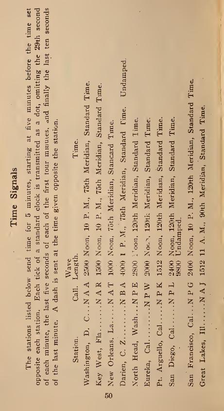
50
i
if
San
Die
go
, C
al.N
PL
2400
No
on
, 120th
Mer
idia
n,
Sta
ndar
d
Tim
e,
9800
Un
dam
ped
.
San
Fra
nci
sco,
Cal
. . .N
P G
2400
No
on
, 10
P.
M.,
120th
Mer
idia
n,
Sta
ndar
d
Tim
e.
Gre
at
Lak
es, Ill.N
AJ
1512
11
A.
M.,
90
th
Mer
idia
n,
Sta
ndar
d
Tim
e.

WIRELESS ALPHABET
Dot and Dash Code
A • 1 B ■###
C — • " • D — • • E _•_ F • • wm •
H • • • •
I • •_
L • M • •
N M •
O M M P • ■ 1 #
Q R »■ t
S
U • • — v • • • m
w x Y z
51

SYMBOLS USED IN RADIO WORK
KEY.
RESISTOR -AAA/VW
VARIABLE AAA A AAA_ RESISTOR--
SWITCH S.P. S.T.
•* S.P.DT..
•* D.P.S.T.
•* D.P.D.T.
•• REVERSING
telreepcheTvIr—XOR (5b
la -AL
TELEPHONE_ TRANSMITTER
THERMOELEMENT.
TRANSFORMER-; -or
VACUUM TUBE--
VOLTMETER
82
...—

ALTERNATOR^—
AMMETER
ANTENNA.
ARC
BATTERY_
BUZZER__
CONDENSOR
VARIABLE CONDENSER
CONNECTION- OF WIRES
NO CONNECTION
COUPLED COILS_
VARIABLE COUPLING
DETECTOR
GALVANOMETER
GAP. PLAIN__• •-
GAP. QUENCHED-|||]||||^—
GROUND.
INDUCTOR.. immr 53

WHAT HAPPENS IN A RECEIVING SET
The aerial is placed in such a position
that it can pick-up or catch the radio waves
(electro-magnetic waves), these waves hav¬
ing been set in motion at the transmitting
or broadcasting station and travel from this
station through space at the rate of 186,000
miles per second. As soon as these waves
set up oscillations in the receiving aerial,
a current is passed from the aerial down
the lead-in wire to the primary coil of the
transformer. The action of the current in
this coil sets up a magnetic field, this cur¬
rent is induced into the secondary coil of
the transformer and this produces a radio
frequency current which is gradually built
up by adjusting the primary and secondary in electrical resonance. The variable con¬ denser is placed in the circuit to allow the secondary circuit to be adjusted to resonance with the primary circuit and also to allow
of close adjustment. The induced current will overflow to the detector circuit as soon as the secondary circuit lias been put in
resonance with the primary circuit. The detector will then rectify this current by
transforming the high frequency to low fre¬ quency. The current then passes to the condenser where it is stored; as soon as a
single wave train has accumulated in the condenser, the condenser will discharge
the current into the phone receivers where by its action in vibrating the diaphragm it makes the magnetic waves received by the aerial audible to the ear.
r,4

WHAT IS MEANT BY WAVELENGTH
Electric-magnetic waves like light waves travel at the rate of 186,000 miles or 300,- 000,000 meters per second, if we are using an alternating current of 25,000 cycles per second and cause a disturbance in the air of that frequency then each cycle will travel from the aerial through space at the rate of 300,000,000 meters per second. So that at the end of the second, just as we are caus¬ ing the last of the 25,000 disturbances the first cycle or disturbance is 300,000,000 meters away. In one second we have made 25.000 separate disturbances which have traveled 300,000.000 meters each disturbance separated by the number of meters that 25.000 divided into 300,000.000 will give— 300,000.000 divided by 25,000 equals 12,000 meters—it is this distance between the sep¬ arate disturbances that is known as the wavelength.
RULE FOR WAVELENGTH
Add the length of the aerial to the lead- in wire. Add to the sum the ground and if more than one wire, one-third of length of aerial. Divide this total by two and add the result to the addition above. The an¬ swer will give the approximate wavelength in meters.—Example—Length of aerial 100 feet, length of ground wire 40 feet, length of lead-in wire 20 feet— 100 4- 40 4- 20 equals 160 feet. One-third of 100 equals 33 -f- 160 equals 193. 193 divided by 2 equals 96, 193 -f 96 equals 284 which is the ap¬ proximate wavelength in meters.
55

FIXED CONDENSER
Fixed condensers are used as shunts across the detector to intensify the incom¬
ing signals and to permit of fine tuning. To make a fixed condenser, first cut a num¬ ber of strips of tin foil into sheets measur¬ ing 3 inches by 2 inches wide. Then lay
two pieces of paraffined paper on the top of a cardboard measuring 3 inches long by 2 inches in width. Then, on top of these
sheets of paraffined paper lay one of the strips of tin foil leaving about inch pro¬ jecting over the end of the paraffined paper under it and, on top of this lay another strip of tin foil, this time letting it project
Fixed Condenser.
—,1 Sheet of Tinfoil.
Tahaffined -paper [
56

J4 inch over the paraffined paper on the opposite end. And so on, the condenser being- built with alternate layers of paraf¬
fined paper and tin foil, until the desired
number of sheets have been built up. Place two pieces of the paraffined paper on top
and over this a strip of cardboard, the same size as that at the bottom. The whole thing is then bound up with thread. Now, lay the condenser on a board fixing on two binding posts, so that they clamp down the projecting ends of tin foil to the wood base.
The condenser is then ready for use in the circuit.
TUNING
The apparatus for tuning a receiving set consists of an adjustable circuit containing variable capacity and inductance. The operation of the tuning apparatus is ve.ry simple. We have already seen that this ap¬ paratus is used to vary the wave length of the receiving set, making it receptive to incoming signals. As in order to receive signals, the receiving set must be adjusted so that the receiving circuits a*re in tune with the transmitting circuit's. In other
words, the time period of oscillation must be the same in both the transmitting and receiving circuits. Thus should we desire to receive the music or speeches from a broadcasting station using a 360 meter
wavelength, then it would be necessary for us to adjust our receiving set to as near
that wavelength as possible to get maxi¬ mum results.
57

HOW TO MAKE A TUNING COIL
A simple tuning or loading coil consists of a cardboard tube around which a wire is wound, and so arranged that more or less of this wire can be cut in or out of the cir¬ cuit by means of a sliding contact point. To build the coil you will need the follow¬ ing :_A cardboard tube 18 or 20 inches long and about 4 inches in diameter, V/2 lbs. of No. 24 copper wire, 2 brass rods a trifle longer than the cardboard tube and approx¬ imately Ya inch square. Two wood discs, Ys of an inch thick and just large enough to fit tightly into the ends of the cardboard tube, two wood pieces for ends, about 4J4 inches square and a wood base to mount the .whole affair on. First wind the wire tightly around the whole length of the card¬ board tube, leaving a free end of wire at each end of the tube. Care should be taken to space the winding evenly. Next, mount the two wood discs in the center of the two wood end pieces. Then slip the discs, one into each end of the cardboard tube and mount the whole affair on the wood base. It is now necessary to mount the brass rods in such a manner that the sliding con¬ tacts on the rod make a good contact on the wire windings of the coil. One end of the wire windings is attached to a bind¬ ing post while the other end is passed through a hole in the cardboard tube, so that it will be out of the way. It will be found advisable to dry all wood used in the building of Radio apparatus, by leaving it for an hour or two in a warm oven, then giving it a coat of shellac. This will elim-
58

ftA
S5
-R
on
■to
EN
D
V/£
¥V
ok)-
Cs(
D£

inate shrinking or warping of the wood. The.re are various makes of coils on the market and I do not think it advisable to go to the trouble of constructing one, as long as they can be bought so cheaply. A number of beginners, however, like to build their own, and it is for them that this article is written.
A COMPLETE RECEIVING SET ON
A COMMON BASE
A—Connection to Aerial.
B—Wood End Pieces.
C—Brass Rods.
D—Connection to Ground.
El—Sliding Contacts.
F—Phone Connections.
G—Crystal and Holder.
H—Adjustable Cat Whisker Holder.
J—Fixed Condenser.
K—Cat Whisker.
60

DE
TE
CT
OR
AN
D
TW
O
ST
AG
E
AM
PL
IFIE
R
61
Desi
gn
ed
to
Op
era
te
Wit
h
On
e
Rad
iotr
on
Dete
cto
r T
ub
e
and
T
wo
Rad
iotr
on
Am
pli
fier
Tubes.

What Do You Know About Radio?
Here’s the Book That Tells You All—
Radio for the Beginner ‘By JAMES R. CAMERON
A few of the chapters this compre¬ hensive work contains:
Construction of Receiving Sets—Operation of Receiving Sets—What Happens in a Receiving Set—What Happens in a Trans¬ mitting Set—How We Hear Music by Wire¬ less—What is Meant by Tuning—What is Meant by Wavelength—Radio Troubles, Their Cause and Remedy—Wiring of Regenerative Receiving Sets—Aerials and Their Uses—Care of Storage Batteries— Lightning Protective Devices—Loud Speak¬ ers—Radio Attachments for the Victrola —Vacuum Tubes—Wiring Diagrams—Con¬ struction of a Crystal Set—How to Make a Fixed Condenser—How to Make a Vari¬ able Condenser—How to Make a Vario¬ meter—How to Make a Reactance Coil— How to Make a Crystal Detector—How to Make a Vario-Coupler—Requirements for Radio Installation — Inductance — Trans¬ formers — Alternating Currents — Genera¬ tion of Electricity—Useful Tables and In¬ formation—Radio Rules and Regulations— Location of Faults—Installation of Ap¬ paratus
£1.00
Write for Your Copy Today
THE TECHNICAL BOOK COMPANY 130 West 42nd Street New York City
62

HOW TO BUILD AND OPERATE A CRYSTAL DETECTOR
RECEIVING SET
Having been asked by the publishers of this book to include an article on the construction operation, and care of a crystal-detector set, that can easily be built at home at very little expense. The writer knows of no better article than the one prepared by the U. S. Bureau of Standards at the request of the States Relations Service of the Dept, of Agriculture. The following is part of the article and tells in simple language how a set can be built at an outlay of approximately Seven Dollars (not including the phone receiver) :
The parts will be mentioned here by refer¬ ence to the letters appearing in Figs. 1 and 2.
A and I are screw eyes sufficiently strong to anchor the antenna at the ends.
B and H are pieces of rope H or Y/i inch in diameter, just long enough to allow the an¬ tenna to swing clear of the two supports.
D is a piece of Vs or l/2 inch rope sufficiently long to make the distance between E and G about 75 ft.
C is a single-block pulley which may be used if readily available.
E and G are two insulators which may be constructed of any dry hard wood of sufficient strength to withstand the strain of the antenna; blocks about I^x2xl0 in. will serve. The holes should be drilled as shown in Fig. 1 sufficiently far from the ends to give proper strength. If wood is used the insulators should be boiled in paraffin for about 1 hour. If porcelain wiring cleats are available they may be substituted instead of the wood insulators. If any unglazed porcelain is used as insula¬ tors, it should be boiled in paraffin the same as the wood. Regular antenna insulators are

advertised on the market, but the two im¬ provised types just mentioned will be satis¬ factory for an amateur receiving antenna.
F is the antenna about 75 ft. between the insulators E and G. The wire may be No. 14 or 16 copper wire either bare or insulated. The end of the antenna farthest from the re¬ ceiving set may be secured to the insulator (E) by any satisfactory method, being careful not to kink the wire. Draw the other end of the antenna wire through the other in¬ sulator (G) to a point where the two insula¬ tors are separated by about 75 ft., twist the insulator (G) so as to form an anchor as shown in Fig. 1. The remainder of the an¬ tenna wire (J) which now constitutes the "lead-in” or drop-wire should be just long enough to reach the lightning switch.
K is the lightning switch. For the purpose of a small antenna this switch may be the or¬ dinary porcelain-base, 30 ampere, single-pole double-throw battery switch. These switches as ordinarily available, have a porcelain base about 1 by 4 in. The ‘‘lead-in” wire (J) is attached to this switch at the middle point. The switch blade should always be thrown to the lower clip when the receiving set is not actually being used and to the upper clip when it is desired to receive signals.
L is the ground wire for the lightning switch; it may be a piece of the same size wire as used in the antenna, of sufficient length to reach from the lower clip of the lightning switch (K) to the clamp on the ground red
(M)\ M is a piece of iron pipe or rod driven
3 to 6 ft. into the ground, preferably where the ground is moist, and extending a sufficient distance above the ground in order that the ground clamp may be fastened to it. Scrape
64

the rust or paint from the pipe before driving in the ground.
N is a wire leading from the upper clip of . the lightning switch through the porcelain tube (O) to the receiving set binding post marked “antenna.”
O is a porcelain tube of sufficient length to reach through the window casing or wall. This tube should be mounted in the casing or wall so that it slopes down toward the outside of the building. This is done to keep the rain from following the tube through the wall to the interior.
Fig. 2 shows the radio receiving set installed in some part of the house.
P is the receiving set which is described in
detail below.
N is the wire leading from the “antenna” binding post of the receiving set through the porcelain tube to the upper clip of the light¬ ning switch. This wire, as well as the wire shown bv Q. should be insulated and prefer- ablv flexible! A piece of ordinary lamp cord might be unbraided and serve for these two
leads. Q is a piece of flexible wire leading from
the receiving set binding post marked “ground” to a water pipe, heating system or some other metallic conductor to grourd. except M. Fig. 1.
f If there are no water pipes nor radiators in the room in which the receiving set is located, the wire should he run out of doors and con-
f nected to a special “ground” below the win¬ dow, which shall not be the same, as the “ground” for the lightning switch. It is essen¬ tial that for the best operation of the receiving set this “ground” he of the very, best type. If
; the soil near the house is dry it is necessary to drive one or more pipes or rods sufficiently
i deep to encounter moist earth and connect the * ground wire to the pipes or rods. This dis-
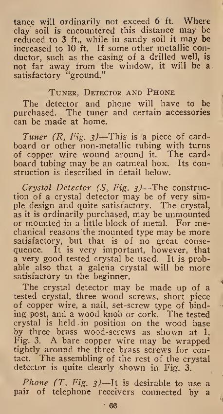
tance will ordinarily not exceed 6 ft. Where clay soil is encountered this distance may be reduced to 3 ft., while in sandy soil it may be increased to 10 ft. If some other metallic con¬ ductor, such as the casing of a drilled well, is not far away from the window, it will be a satisfactory “ground.”
Tuner, Detector and Phone
The detector and phone will have to be purchased. The tuner and certain accessories can be made at home.
Tuner (R, Fig. 3)—This is a piece of card¬ board or other non-metallic tubing with turns of copper wire wound around it. The card¬ board tubing may be an oatmeal box. Its con¬ struction is described in detail below.
Crystal Detector (S, Fig. 3)—The construc¬ tion of a crystal detector may be of very sim¬ ple design and quite satisfactory. The crystal, as it is ordinarily purchased, may be unmounted or mounted in a little block of metal. For me¬ chanical reasons the mounted type may be more satisfactory, but that is of no great conse¬ quence. It is very important, however, that a very good tested crystal be used. It is prob¬ able also that a galena crystal will be more satisfactory to the beginner.
The crystal detector may be made up of a tested crystal, three wood screws, short piece of copper wire, a nail, set-screw type of bind¬ ing post, and a wood knob or cork. The tested crystal is held.in position on the wood base by three brass wood-screws as shown at 1, Fig. 3. A bare copper wire may be wrapped tightly around the three brass screws for con¬ tact. The assembling of the rest of the crystal detector is quite clearly shown in Fig. 3.
Phone (T, Fig. 3)—It is desirable to use a pair of telephone receivers connected by a
66

head band, usually called a double telephone headset. The telephone receivers may be any of the standard commercial makes having a
resistance of between 2000 and 3000 ohms. The double telephone receivers will' cost more than all the other parts of the station combined,
67

but it is desirable to get them, especially if one plans to improve his receiving set l^ter. If one does not care to invest in a set of
double telephone receivers, a single telephone receiver with a head band may be used;;,, it gives results somewhat less satisfactory. ;
08
Accessories—Under the heading of accessory equipment may be listed binding posts, switch arms, switch contacts, test-buzzer, dry battery,
and boards on which to mount the complete apparatus. The binding posts, switch arms and switch contacts may all be purchased from dealers who handle such goods or they may be quite readily improvised at home. There is nothing peculiar about the pieces of wood on which the equipment is mounted. They may be obtained from a dry packing-box and covered with paraffin to keep out moisture.
Details of Construction
The following is a detailed description of the method of winding the coil, construction of the wood panels, and mounting and wiring the apparatus:
Tuner—See R, Fig. 3. Having supplied one¬ self with a piece of cardboard tubing 4 in. in diameter and about J4 pound of No. 24 (or No. 26) double cotton covered copper wire, one is ready to start the winding of the tuner. Punch two holes in the tube about J/2 in. from one end as shown at 2 on Fig. 3. Weave the wire through these holes in such a way that the end of the wire will be quite firmly an¬ chored, leaving about 12 inches of the wire free for connections. Start with the remainder of the wire to wrap the several turns in a single layer about the tube, tightly and closely together. After 10 complete turns have been wound on the tube hold those turns snugly while a tap is being taken off. This tap is made by making a 6 in. loop of the wire and twisting it together at such a place that it
will be slightly staggered from the first tap,

This method of taking off taps is shown quite clearly at U, Fig. 3. Proceed in this manner until 7 twisted taps have been taken off at every 10 turns. After these first 70 turns have been wound on the tube then take off a 6 in.
twisted tap for every succeeding single turn until 10 additional turns have been wound on the tube. After winding the last turn of wire anchor the end by weaving it through two holes punched in the tube much as was
done at the start, leaving about 12 in. of wire free for connecting. It is to be understood that each of the 18 taps is slightly staggered from the one just above, so that the several taps will not be bunched along one line on
the cardboard tube. See Fig. 3. It would
be advisable, after winding the tuner as just described, to dip the tuner in hot paraffin. This will help to exclude moisture.
Upright Panel and Base—Having completed
the tuner to this point, set it aside and con¬ struct the upright panel shown in Fig. 4. This panel may be a piece of wood approximately
54 in. thick. The position of the several holes for the binding posts, switch arms and switch
contacts may first be laid out and drilled. The
"antenna” and '‘ground” binding posts may
be ordinary % in. brass bolts of sufficient length
and supplied with three nuts and two washers. The first nut binds the bolt to the panel, the second nut holds one of the short pieces of
stiff wire, while the third nut holds the an¬
tenna or ground wire as the case may be. The switch arm with knob shown at V, Fig. 3,
may be purchased in the assembled form or it
may be constructed from a thin slice cut from
a broom handle and a bolt of sufficient length
equipped with four nuts and two washers to-
70

gether with a narrow strip of thin brass some¬ what as shown. The switch contacts (W, Fig. 3) may be of the regular type furnished
for this purpose or they may be brass bolts eauipped with one nut and one washer each or thev may even be nails driven through the
71

panel with an individual tap fastened under the head or soldered to the projection of the nail through the panel. The switch contacts
should be just close enough that the switch arm will not drop between the contacts, but also far enough apart that the switch arm
72

can be set so as to touch only one contact at a time.
The telephone binding post should preferably be of the set screw type as shown at X, Fig. 3.
Instructions for Wiring
' Having constructed the several parts just mentioned and mounted them on the wood base, one is ready to connect the several taps to the switch contacts and attach the other necessary wires. Scrape the cotton insulation from the loop ends of the sixteen twisted taps as well as from the ends of the two single taps coming from the first and last turns. Fasten the bare ends of these wires to the proper switch contacts as shown by the corresponding numbers in Fig. 3. One should be careful not to cut or break any of the looped taps. It would be preferable to fasten the connecting wires to the switch contacts by binding them between the washer and the nut as shown at 3. Fig. 3. A wire is run from the back of the
binding post marked “ground” (Fig. 3) to the back of the left-hand switch-arm bolt (Y),
thence to underneath the left-hand binding
post marked “phones.” A wire is then run from underneath the right-hand binding post
marked “phones” to underneath the binding
post (4, l;ig. 3), which forms a part of the crystal detector. A piece of* No. 24 bare cop¬ per wire about 2^2 in. long, one end of which
is twisted tightly around the nail (the nail passing through binding post 4), the other end
of which rests gently by its own weight on
the crystal (1). The bare copper wire which was wrapped tightly around the three brass wood-screws holding the crystal in place is lead
to and fastened at the rear of the right-hand
switch arm bolt (v), thence to the upper left-
hand binding post marked “antenna.” As
73

much as possible of this wiring is shown in Fig. 3.
Directions for Operating
After all the parts of this crystal-detector radio receiving set have been constructed and assembled the first essential operation is to adjust the little piece of wire, which rests lightly on the crystal, to a sensitive point. This may be accomplished in several different ways; the use of a miniature buzzer trans¬ mitter is very satisfactory. Assuming that the most sensitive point on the crystal has been found by method described in paragraph below, “The Test Buzzer,” the rest of the operation is to get the radio receiving set in resonance or in tune with the station from which one wishes to hear messages. The tuning of the receiving set is attained by adjusting the in¬ ductance of the tuner. That is, one or both of the switch arms are rotated until the proper number of' turns of wire of the tuner are made a part of the metallic circuit between the antenna and ground, so that together with the capacity of the antenna the receiving cir¬ cuit is in resonance with the particular trans¬ mitting station. It will be remembered that there are 10 turns of wire between each of the first 8 switch contacts and only one turn of wire between each 2 of the other contacts. The tuning of the receiving set is best accomplished by setting the right-hand switch arm on con¬ tact (1) and rotating the left-hand switch arm over all its contacts. If the desired sig¬
nals are not heard, move the right-hand switch arm to contact (2) and again rotate the left- hand switch arm throughout its range. Pro¬
ceed in this manner until the desired signals are heard.
It will be advantageous for the one using
this radio receiving equipment to find out the
74

wave frequencies (wave-length) used by the several radio transmitting stations in his im¬ mediate vicinity.
The Test Buzzer (Z, Fig. 3)—As mentioned previously, it is easy to find the more sensitive spots on the crystal by using a test buzzer. The test buzzer is used as a miniature local transmitting set. When connected to the re¬ ceiving set as shown at Z, Fig. 3, the current produced by the buzzer will be converted into sound by the telephone receivers and the crystal, the loudness of the sound depending on what part of the crystal is in contact with the fine wire. To find the most sensitive spot connect the test buzzer to the receiving set as directed, close the switch (5, Fig. 3) (and if necessary adjust the buzzer armature so that a clear note is emitted by the buzzer), set the right-hand switch arm on contact point No. 8, fasten the telephone receivers to the binding posts marked “phones,” loosen the set screw of the binding post slightly and change the position of the fine wire (6, Fig. 3) to several positions of contact with the crystal unit until the loudest sound is heard in the phones, then tighten the binding post set screw (4) slightly.
Fixed Condenser
75

How to Build Your Own
Receiving Set
Full instructions with diagrams and drawings, making it easy for the be¬ ginner to build his own set and listen
in to the daily concerts
cents
From Your Dealer or Direct from
THE
TECHNICAL BOOK CO. Bush Building
130 West 42nd St., New York City
76
REQUIREMENTS OF NATIONAL
ELECTRICAL CODE-RADIO
INSTALLATION
Where an indoor aerial is used, no special safe-guards are necessary, but where the aerial is placed outside the building, a ground wire should be carried from the aerial in the most direct line to the ground. This wire should not be smaller than No. 8 B & S gauge. Should it not be possible to make a suitable ground connection outside the building, then the ground wire should be lead into the cellar of building through a lead-in insulator and connection made to the water main. Do not under any circumstances connect the ground wire to a gas pipe. The lead-in wire from the aerial to the receiving set shoul be pro¬ tected by one of the approved types of light¬ ning arrestors now on the market. This ar¬ restor should be installed on the lead-in wire outside the building.
A. Aerial conductors must be installed and constructed to prevent accidental contact with the conductors carrying a current over 600 volts. Aerial supports must be constructed and in¬ stalled in a strong and durable manner. Aerial wires leading from same to ground switch must be mounted firmly on approved insulating sup¬ ports which may be constructed of wood, not iron pin. or brackets equipped with porcelain knobs or petticoat insulators. Insulators must be so installed as to maintain the conductors at least five inches clear of the surface of the building wall. In passing the aerial conductor through the side of the building a continuous tube or bushing must extend five inches beyond the surface of the wall on both sides. The porcelain tube will not be approved in this case. Ground switches shall be mounted so that the current carrying parts will be at least five inches clear of the building walls and
77

located preferably in the most direct line be¬ tween the aerial and the point of ground con¬ nection. The conductor from the ground switch to ground connection must be securely supported.
B. Aerial conductors must be effectively and permanently grounded at all times when the station is not in operation, by a conductor the periphery of the cross section of which is not less than three-quarters of an inch. The ground conductor must be of copper or other metal which will not corrode excessively under existing conditions. Where ground_ conductor is over twenty-five feet in length it shall be insulated throughout its entire length in a , similar manner to wires attached to aerial con¬ ductors. Ground connections should be made in accordance with the requirements as set forth above, except where variations from these requirements may be allowed by special permission in writing from the Board of Fire Underwriters.
C. In radio stations used for receiving only the ground switch may be replaced by a simi¬ larly mounted and grounded short (one-eighth inch or less) or vacuum type lightning ar¬ restor. The current carrying parts must be t five inches from the building.
D. Where the aerial is grounded as specified in sections A and B the switch employed to join the aerial to the ground connection must be a knife switch, the blade of which must have a periphery of not less than three-quar¬ ters of an inch so that when open the current carrying parts to which the aerial and ground connection wires are attached will be separated at least by five inches. The base of the switch must be of a material suitable for high fre- qency service. Slate will not be approved.
78

E. When supply is obtained direct from street service the current must be installed in metal conduit or armored cable. In order to protect the supply system from high potential surges there must be provided two condensers, each of not less than one-half microfarad capacity and capable of withstanding 600-volt tests in series across the line with mid-point grounded. A capacity fuse not larger than ten amperes capacity must be connected between each condenser and the line wire connected to it. Each condenser must be protected by a shunting fixed spark gap of one thirty-second of an inch separation or less. Another way of protecting the supply system from high po¬ tential surges is by means of two incandescent lamps connected in series across the line with the mid-point grounded.
F. Transformer, voltage reducers, keys and similar devices must be of types specially de¬ signed for the service.
Crystal Detector
79

‘BOOKS BY THE SAME
cAUTHOR
Radio tor the Beginner . . £1.00
How to Build your Own Receiving Set. Full Directions with Drawing
.25
Text Book on Wireless . . 3.00
Motion Picture Projection The standard authority on this subject, 560 pages, over 200 Illustrations. Used by the U. S. Government and Boards of Education throughout the country.
3.50
Pocket Reference Book . . For Projectionists and Managers
1.00
Motion Picture Optics . 2.50
Elementary Text Book on Projection.
From Your Dealer or bookseller
or Direct from
THE TECHNICAL BOOK CO. 130 West 42nd St., New York City

t' •
• V •
' r!
,-1
--
' - .• 1 • * '
v. • >
* A i • • ' "x
•-» > / Hf l, .. • -••V-.-' r . :• >k r «> <;#. -
■ • '
*vfc<-
/l ’ >V *
V vi
; v- \:®.' :-■• « y! ■; . .V-- •■"■' '•>• '•. ,y, ■» •• ,. ,V • v ■ . i ' •; '. '.V . '• •'•<•• •}"
■
.. . . ir • ••. *v ’■! V* ’

„ 0 033 266 374,4 TEChi'dLAL
BOOK CO. PUBLISHERS OF
Radio Dictionary • . • • $ .50
Text Book on Wireless . . 3.00
Radio for the Beginner • • 1.00
How to Build Your Own Receiving Set .... .25
Motion Picture Projection . 3.50
Elementary Text Book on Projection. 2.00
Motion Picture Optics . . 2.50
Elementary Electricity . . 2.00
Pocket Reference Book For Projectionists and Managers • 1.00
From all dealers and booksellers or Direct from
THE
TECHNICAL BOOK CO. 130 West 42nd St., New York City