radio frequency and modulation standardmicroelectronics.esa.int/vhdl/pss/pss-04-105.pdf · radio...
TRANSCRIPT

ESA PSS-04-105, Issue 2.4
November, 1996
european space agency
agence spatiale européenne
RADIO FREQUENCY AND
MODULATION STANDARD
Prepared by:
The Standards Approval Board (STAB)
for Space Data Communications
To be Approved by:
[The Inspector General, ESA]

ESA PSS-04-105, Issue 2.4 (November 1996) i
SPACE DATA COMMUNICATIONS
PROCEDURES, SPECIFICATIONS & STANDARDS
Space Data Communications is the subject of the PSS-04 branch of the ESA
Procedures, Specifications & Standards (PSS) series. This branch is further divided
into two subbranches:
! the Space Link Standards and Protocols subbranch (document
reference nos.: ESA PSS-04-1XX);
! the Spacecraft Data Interfaces and Protocols subbranch (document
reference nos.: ESA PSS-04-2XX).
The Space Data Communications PSS documents have the purpose of
ensuring the compatibility of spacecraft TT&C subsystems with the relevant ESA
infrastructure (i.e. the ESA (ESOC) tracking and data-communication network and
the ESA (ESTEC) satellite check-out facilities).

ESA PSS-04-105, Issue 2.4 (November 1996) ii
DOCUMENT CHANGE RECORD
Date Issue Chapter Description of Changes
April Draft all Changes in agreement with the Rationale for updating the
1995 Issue 2.1 chapters currently applicable Issue 1 of December 1989
Dec. Draft all Changes in agreement with decisions taken by Panel
1995 Issue 2.2 chapters members
June Draft Issue chapter 5, Changes in agreement with decisions taken by Panel
1996 2.3 App. B members
and D
Nov. Draft Issue chapter 6 Changes in agreement with decisions taken by Panel
1996 2.4 and 7 members

ESA PSS-04-105, Issue 2.4 (November 1996) iii
REFERENCES
[1] Ranging Standard (ESA PSS-04-104), Issue 2 of Volume 1, March 1991,
European Space Agency.
[2] Telemetry Channel Coding Standard (ESA PSS-04-103), Issue 1,
September 1989, European Space Agency.
[3] Packet Telemetry Standard (ESA PSS-04-106), Issue 1, January 1988,
European Space Agency.
[4] Packet Telecommand Standard (ESA PSS-04-107), Issue 2, April 1992,
European Space Agency.
[5] ITU Radio Regulations, Edition 1994, Geneva
[6] CCSDS Radio Frequency and Modulation Systems, Part 1, Earth Stations
and Spacecraft, Blue Book, CCSDS 401.0-B, November 1994
[7] Handbook of the Space Frequency Coordination Group, Edition October
1996

ESA PSS-04-105, Issue 2.4 (November 1996) iv
CONTENTS
1. PURPOSE AND SCOPE . . . . . . . . . . . . . . . . . . . . . . . . . . . . . . . . . . . . . . . . . . . . . . . . 1
1.1 PURPOSE . . . . . . . . . . . . . . . . . . . . . . . . . . . . . . . . . . . . . . . . . . . . . . . . . . . . . . . 1
1.2 SCOPE . . . . . . . . . . . . . . . . . . . . . . . . . . . . . . . . . . . . . . . . . . . . . . . . . . . . . . . . . . 1
2. APPLICABILITY . . . . . . . . . . . . . . . . . . . . . . . . . . . . . . . . . . . . . . . . . . . . . . . . . . . . . . 2
3. FREQUENCY ALLOCATIONS, ASSIGNMENT AND USE . . . . . . . . . . . . . . . . . . . . . . . 3
3.1 FREQUENCY ALLOCATIONS TO THE SPACE OPERATION, SPACE RESEARCH
AND EARTH EXPLORATION SATELLITE SERVICES . . . . . . . . . . . . . . . . . . . . . . 3
3.1.1 General . . . . . . . . . . . . . . . . . . . . . . . . . . . . . . . . . . . . . . . . . . . . . . . . . . . . 3
3.1.2 Definitions of the Space Radio Communication Services . . . . . . . . . . . . . . . 3
3.1.3 Frequency Bands Allocated to the Space Radiocommunications Services in
the Framework of this Standard . . . . . . . . . . . . . . . . . . . . . . . . . . . . . . . . . 4
3.2 SPECIFIC CONDITIONS FOR THE USE OF CERTAIN FREQUENCY BANDS . . . . 6
3.2.1 2025 - 2110 MHz / 2200 - 2290 MHz . . . . . . . . . . . . . . . . . . . . . . . . . . . . . . 6
3.2.1.1 2025 - 2110 MHz . . . . . . . . . . . . . . . . . . . . . . . . . . . . . . . . . . . . . 6
3.2.1.2 2200 - 2290 MHz . . . . . . . . . . . . . . . . . . . . . . . . . . . . . . . . . . . . . 6
3.2.2 8025 - 8400 MHz . . . . . . . . . . . . . . . . . . . . . . . . . . . . . . . . . . . . . . . . . . . . 6
3.2.3 8450 - 8500 MHz . . . . . . . . . . . . . . . . . . . . . . . . . . . . . . . . . . . . . . . . . . . . 6
3.2.4 16.6 - 17.1 GHz / 14.0 - 15.35 GHz . . . . . . . . . . . . . . . . . . . . . . . . . . . . . . . 7
3.2.5 40.0 - 40.5 GHz / 37.0 - 38 GHz . . . . . . . . . . . . . . . . . . . . . . . . . . . . . . . . . 7
3.3 FREQUENCY ASSIGNMENT PROCEDURE . . . . . . . . . . . . . . . . . . . . . . . . . . . . . . 8
3.3.1 Choice of Frequencies . . . . . . . . . . . . . . . . . . . . . . . . . . . . . . . . . . . . . . . . 8
3.3.2 Notification of Frequencies . . . . . . . . . . . . . . . . . . . . . . . . . . . . . . . . . . . . . 8
4. REQUIREMENTS ON TRANSMITTED SIGNALS . . . . . . . . . . . . . . . . . . . . . . . . . . . . . 9
4.1 TURNAROUND FREQUENCY RATIO FOR COHERENT TRANSPONDERS . . . . . 9
4.2 CARRIER FREQUENCY STABILITY REQUIREMENTS . . . . . . . . . . . . . . . . . . . . 10
4.2.1 Spacecraft Transmitter . . . . . . . . . . . . . . . . . . . . . . . . . . . . . . . . . . . . . . . 10
4.2.2 Spacecraft Receiver . . . . . . . . . . . . . . . . . . . . . . . . . . . . . . . . . . . . . . . . . 10
4.2.3 Ground Station Equipment . . . . . . . . . . . . . . . . . . . . . . . . . . . . . . . . . . . . 11
4.2.4 Requirements for Doppler Tracking . . . . . . . . . . . . . . . . . . . . . . . . . . . . . . 11
4.3 POLARISATION . . . . . . . . . . . . . . . . . . . . . . . . . . . . . . . . . . . . . . . . . . . . . . . . . . 11
4.4 BANDWIDTH CONSIDERATIONS . . . . . . . . . . . . . . . . . . . . . . . . . . . . . . . . . . . . 12
4.4.1 Definitions . . . . . . . . . . . . . . . . . . . . . . . . . . . . . . . . . . . . . . . . . . . . . . . . . 12
4.4.2 Requirements on Occupied Bandwidth . . . . . . . . . . . . . . . . . . . . . . . . . . . 13
4.5 REQUIREMENTS ON EMISSIONS . . . . . . . . . . . . . . . . . . . . . . . . . . . . . . . . . . . . 14

ESA PSS-04-105, Issue 2.4 (November 1996) v
4.5.1 Spurious Emission Power Level . . . . . . . . . . . . . . . . . . . . . . . . . . . . . . . . 14
4.5.1.1 Transmitter Spurious Emissions and Harmonics . . . . . . . . . . . . 14
4.5.1.3 Protection of Deep Space Research Bands . . . . . . . . . . . . . . . . 15
4.5.1.4 Protection of Ariane RF systems . . . . . . . . . . . . . . . . . . . . . . . . 16
4.5.2 Cessation of Emissions . . . . . . . . . . . . . . . . . . . . . . . . . . . . . . . . . . . . . . . 16
4.5.3 Power Flux Density Limits . . . . . . . . . . . . . . . . . . . . . . . . . . . . . . . . . . . . . 16
4.5.4 Power Limits for Earth Station Emissions . . . . . . . . . . . . . . . . . . . . . . . . . 17
4.5.5 Time Limitations on Transmissions . . . . . . . . . . . . . . . . . . . . . . . . . . . . . . 18
5. MODULATION REQUIREMENTS . . . . . . . . . . . . . . . . . . . . . . . . . . . . . . . . . . . . . . . . 19
5.1 PHASE MODULATION WITH RESIDUAL CARRIERS . . . . . . . . . . . . . . . . . . . . . 19
5.1.1 Application . . . . . . . . . . . . . . . . . . . . . . . . . . . . . . . . . . . . . . . . . . . . . . . . 19
5.1.2 Modulating Waveforms . . . . . . . . . . . . . . . . . . . . . . . . . . . . . . . . . . . . . . . 19
5.1.3 PCM Waveforms and Data Rates . . . . . . . . . . . . . . . . . . . . . . . . . . . . . . . 20
5.1.4 Use of Subcarriers . . . . . . . . . . . . . . . . . . . . . . . . . . . . . . . . . . . . . . . . . . 22
5.1.4.1 Permitted Subcarriers . . . . . . . . . . . . . . . . . . . . . . . . . . . . . . . . 22
5.1.4.2 Subcarrier Frequency Stability . . . . . . . . . . . . . . . . . . . . . . . . . . 23
5.1.4.3 Subcarrier Modulation . . . . . . . . . . . . . . . . . . . . . . . . . . . . . . . . 23
5.1.5 Data Transition Density . . . . . . . . . . . . . . . . . . . . . . . . . . . . . . . . . . . . . . . 24
5.1.6 Carrier Modulation Index . . . . . . . . . . . . . . . . . . . . . . . . . . . . . . . . . . . . . . 24
5.1.7 Sense of Modulation . . . . . . . . . . . . . . . . . . . . . . . . . . . . . . . . . . . . . . . . . 25
5.1.8 Modulation Linearity . . . . . . . . . . . . . . . . . . . . . . . . . . . . . . . . . . . . . . . . . 25
5.1.9 Residual Amplitude Modulation . . . . . . . . . . . . . . . . . . . . . . . . . . . . . . . . . 25
5.1.10 Carrier Phase Noise . . . . . . . . . . . . . . . . . . . . . . . . . . . . . . . . . . . . . . . . . 25
5.1.11 Requirements on Residual Carrier and Spurious Lines . . . . . . . . . . . . . . . 25
5.2 SUPPRESSED CARRIER MODULATION . . . . . . . . . . . . . . . . . . . . . . . . . . . . . . 26
5.2.1 Application and Modulation Schemes . . . . . . . . . . . . . . . . . . . . . . . . . . . . 26
5.2.2 Modulating Waveforms . . . . . . . . . . . . . . . . . . . . . . . . . . . . . . . . . . . . . . . 26
5.2.3 Carrier Modulation . . . . . . . . . . . . . . . . . . . . . . . . . . . . . . . . . . . . . . . . . . . 27
5.2.4 Data Transition Density . . . . . . . . . . . . . . . . . . . . . . . . . . . . . . . . . . . . . . 28
5.2.5 Residual Amplitude Modulation . . . . . . . . . . . . . . . . . . . . . . . . . . . . . . . . . 28
5.2.6 Carrier Phase Noise . . . . . . . . . . . . . . . . . . . . . . . . . . . . . . . . . . . . . . . . . 28
5.2.7 Requirements on Spectral Lines and Residual Carrier . . . . . . . . . . . . . . . . 28
6. LINK ACQUISITION PROCEDURES . . . . . . . . . . . . . . . . . . . . . . . . . . . . . . . . . . . . . . 29
6.1 SPACE-EARTH . . . . . . . . . . . . . . . . . . . . . . . . . . . . . . . . . . . . . . . . . . . . . . . . . . 29
6.2 EARTH-SPACE (2025-2110 MHz) . . . . . . . . . . . . . . . . . . . . . . . . . . . . . . . . . . . . 29
6.3 EARTH-SPACE (2110 - 2120 MHz) . . . . . . . . . . . . . . . . . . . . . . . . . . . . . . . . . . . 30
6.4 EARTH-SPACE (7190 - 7235 MHz) . . . . . . . . . . . . . . . . . . . . . . . . . . . . . . . . . . . 31
6.5 EARTH-SPACE (7145 - 7190 MHz) . . . . . . . . . . . . . . . . . . . . . . . . . . . . . . . . . . . 31
7. CROSS SUPPORT FROM OTHER NETWORKS . . . . . . . . . . . . . . . . . . . . . . . . . . . . 32

ESA PSS-04-105, Issue 2.4 (November 1996) vi
7.1 NETWORK COMPATIBILITY . . . . . . . . . . . . . . . . . . . . . . . . . . . . . . . . . . . . . . . . 32
7.2 SHUTTLE/DETACHED-PAYLOAD COMPATIBILITY . . . . . . . . . . . . . . . . . . . . . . 32
7.3 NASA MK IVA DSN COMPATIBILITY . . . . . . . . . . . . . . . . . . . . . . . . . . . . . . . . . . 33
7.4 DATA RELAY SATELLITE COMPATIBILITY . . . . . . . . . . . . . . . . . . . . . . . . . . . . . 36
APPENDIX A - ACRONYMS AND ABBREVIATIONS USED IN THIS STANDARD . . . . . . 37
APPENDIX B - FREQUENCY ASSIGNMENT PROCEDURE . . . . . . . . . . . . . . . . . . . . . . . 39
APPENDIX C - PROTECTION OF ARIANE RF SYSTEM . . . . . . . . . . . . . . . . . . . . . . . . . 50
APPENDIX D - RF INTERFACE CONTROL REQUIREMENTS . . . . . . . . . . . . . . . . . . . . . 52

ESA PSS-04-105, Issue 2.4 (November 1996) 1
1. PURPOSE AND SCOPE
1.1 PURPOSE
The purpose of this Standard is to:
! Ensure compatibility of frequency usage and modulation schemes between ESAspacecraft and ESA-controlled Earth stations (ESTRACK) for the SPACEOPERATION, SPACE RESEARCH and EARTH EXPLORATION SATELLITEservices;
! Ensure, so far as possible, compatibility between the Agency's spacecraft and other
networks with which they may have to work;
! Ensure standardisation of frequency usage and modulation schemes within theAgency;
! Ensure the compliance of ESA spacecraft and Earth station parameters withinternational radio regulatory provisions (Radio Regulations of the InternationalTelecommunication Union (ITU)) and with national regulatory provisions (e.g. nationalfrequency plans);
! Ensure that the parameters of ESA spacecraft and Earth stations are properly chosenand listed in advance of their use, thus permitting coordination with other interestedparties;
! Ensure that, within the above limitations, the frequency usage and modulationschemes of the Agency are optimised.
1.2 SCOPE
This Standard defines the radio communication techniques to be used for the transfer ofinformation between spacecraft and Earth stations in both directions, and for the trackingsystems required for orbit determination. It comprises the following subjects:
! Frequency allocation, assignment and use.
! Requirements on transmitted signals concerning spectral occupation, RF powerlevels, protection of other radio services, etc.
! Definition of the permissible modulation methods and parameters.
! Specification of the major technical requirements which are relevant for the interfacebetween spacecraft and Earth stations.
! Operational aspects, e.g. acquisition.
! Cross-support.

ESA PSS-04-105, Issue 2.4 (November 1996) 2
For ESA spacecraft supported by data relay satellites, PSS-04-109 is applicable.1
This Standard is not applicable to the Meteorological Satellite service.2
2. APPLICABILITY
This Standard is applicable to all ESA spacecraft which are supported by Earth-stations and to1
all ESA controlled Earth stations (ESTRACK) operating in the SPACE OPERATIONS, SPACERESEARCH and EARTH EXPLORATION SATELLITE services as defined in the ITU RadioRegulations. 2
Other space telecommunication services are not covered in the present issue. Standards forthese services will be added as and when they are developed.
The requirements specified by this document supersede any similar requirements contained inany of the related standards published prior to this Issue. In the case of conflict, this Standardshall take precedence.
For particular cases where compliance with this Standard is not feasible, owing tomission-specific requirements, deviations may be warranted. Waivers to requirements definedin this Standard may be obtained when:
! the technical and/or operational need for such deviations has been demonstrated and
! it has been demonstrated that the intended change can be supported by existingsystems.
Waivers to provisions of the ITU Radio Regulations cannot be granted.
Requests for waivers should be addressed by the Project manager to the ESA StandardsApproval Board (STAB) for Space Data Communications. Such requests should be submitted asearly as possible, preferably during the study phase of the project.

ESA PSS-04-105, Issue 2.4 (November 1996) 3
3. FREQUENCY ALLOCATIONS, ASSIGNMENT AND USE
3.1 FREQUENCY ALLOCATIONS TO THE SPACE OPERATION, SPACERESEARCH AND EARTH EXPLORATION SATELLITE SERVICES
3.1.1 General
The use of frequencies by radiocommunication services is governed by the provisions ofthe Radio Regulations of the International Telecommunication Union (ITU/RR).Consequently, any frequency assignment made to a particular user (spacecraft) has to bemade in accordance with the ITU/RR, which
! define the various radiocommunication services (see Subsection 3.1.2),
! allocate frequency bands to them (see Subsection 3.1.3),
! lay down procedures to be followed for a frequency assignment and the frequencynotification with the Radiocommunications Bureau of the ITU (see Subsection 3.3),
! specify technical conditions for the frequency use (see Section 4).
3.1.2 Definitions of the Space Radio Communication Services
Space Operation Service (SO), (ITU/RR/25 [5])
"A radiocommunication service concerned exclusively with the operation of spacecraft, inparticular space tracking, space telemetry and space (tele)command (TTC). Thesefunctions will normally be provided within the service in which the spacecraft is operating".
Earth Exploration Satellite Service (EES), (ITU/RR48 [5])
"A radiocommunication service between Earth stations and one or more space stations,which may include links between space stations, in which:
! information relating to the characteristics of the Earth and its natural phenomena,including data relating to the state of the environment, is obtained from activesensors or passive sensors on Earth satellites;
! similar information is collected from airborne or Earth-based platforms;
! such information may be distributed to Earth stations within the system concerned;
! platform interrogations may be included.
This service may also include feeder links necessary for its operation"

ESA PSS-04-105, Issue 2.4 (November 1996) 4
Space Research Service (SR), (ITU/RR/52 [5])
"A radio communication service in which spacecraft and other objects in space are usedfor scientific and technological research".
Deep Space (DS) (ITU/RR/169 [5])
"Space at distances from the Earth of equal to, or greater than, 2×10 kilometers". 6
The following terminology will be used in this standard:
Category A: Those spacecraft having an altitude above the Earth's surface of less than2 × 10 km.6
Category B: Those spacecraft having an altitude above the Earth's surface of equal to,or greater than, 2 × 10 km.6
3.1.3 Frequency Bands Allocated to the Space Radiocommunications Services in theFramework of this Standard
The following frequency bands, allocated to the above listed radiocommunication services,are available to ESA satellites operating in one or several of the aboveradiocommunications services (see Table 3.1):
Frequency Band Allocated Service Direction Allocation Status (MHz) (3) (5)(1),(2)
2025 - 2110 SR, SO, EES Earth-space PRIMARY2110 - 2120 SR (DS) Earth-space PRIMARY
2200 - 2290 SR, SO, EES Space-Earth PRIMARY2290 - 2300 SR (DS) Space-Earth PRIMARY
7145 - 7190 * SR (DS) Earth-space FN (Art.14)7190 - 7235 * SR Earth-space FN (Art. 14)
8025 - 8400 EES Space-Earth FN (Art. 14)8400 - 8450 SR (DS) Space-Earth PRIMARY8450 - 8500 SR Space-Earth PRIMARY
14000 - 14300* SR Space-Earth (4) secondary14400 - 14470* SR Space-Earth secondary14500 - 15350* SR Space-Earth (4) secondary
16600 - 17100* SR Earth-space secondary
31800 - 32300* SR (DS) Earth-space PRIMARY 34200 - 34700*
SR (DS) space-Earth PRIMARY
37000 - 38000* SR Space-Earth PRIMARY40000 - 40500* SR Earth-space PRIMARY
TABLE 3.1: Frequency Allocations to the Space Operation, Space Research and Earth Exploration Services (6)

ESA PSS-04-105, Issue 2.4 (November 1996) 5
Explanatory Notes:
(1) Frequency Band Implementation Status
The frequency bands marked by an asterisk are not yet implemented in theESTRACK Network. Any potentially interested user is invited to contact theresponsible department for operations in ESA.
(2) Special Conditions Governing the Use of Particular Frequency Bands
The use of certain frequency bands is governed by specific conditions (see 3.2),which are laid down in SFCG and CCSDS RF and Modulation SubpanelRecommendations [6][7]. The ESA Frequency Management Office will informapplicants for frequency assignments (see 3.3 below) about any evolution of theseconditions, which may have occurred since the issue of this Standard.
(3) Use of Frequency Bands Allocated to the Space Research (Deep Space) Service
The frequency bands allocated to the Space Research (Deep Space) service shallonly be used by category B spacecraft.
(4) Direction Indicator
SFCG recommends that these bands be used in the space-Earth direction [7].
(5) Allocation Status
The ITU RR define a number of different modes of allocations: PRIMARY, secondary,allocation by Footnote and allocations under Article 14.
Primary allocation:A service with a primary allocation status
! must only share with other co-primary services, which may be allocated in thesame band, under defined conditions.
! has priority over other allocations, such as secondary; it is not obliged toprotect them or to accept interference caused by them.
Secondary allocation:A service with a secondary allocation status
! shall not cause harmful interference to any station of a service allocated in thesame band with a primary status.
! cannot claim protection from interference caused by stations of a primaryservice sharing the same frequency band.
Allocation by Footnote:An allocation by footnote in the ITU/RR may contain additional regulatory conditionsfor the use of the frequency band, such as supplementary co-ordination inaccordance with Art. 14, or limit the allocation to less than an entire ITU Region.

ESA PSS-04-105, Issue 2.4 (November 1996) 6
Allocation under Article 14:In the context of this Standard, this Article is only applicable to a few frequencybands; it contains a supplementary (co-ordination) procedure which stipulates a prioragreement with (an) administration(s) operating primary services in the band.
3.2 SPECIFIC CONDITIONS FOR THE USE OF CERTAIN FREQUENCY BANDS
3.2.1 2025 - 2110 MHz / 2200 - 2290 MHz
3.2.1.1 2025 - 2110 MHz
The 2025 - 2110 MHz band is allocated to Earth-space and space-space transmissions.In order to minimise interference to Earth-space links of other spacecraft or to space-space links from data relay satellites to user satellites, which are particularly susceptibleto RFI, the EIRP transmitted from the Earth station shall be selected in such a way asto allow for the smallest practicable link margin. Earth station transmitters shall beequipped with adjustable RF output power.
Excessive Earth station EIRP not only complicates frequency coordination with otherusers, but may also prohibit operations totally at some sites. As a means of RFImitigation, Earth-to-space transmissions may have to be interrupted during thoseperiods, when they cause RFI to other (priority) users. With a view to alleviating thefrequency sharing situation, operators shall abstain from activating the Earth-to-spacelinks during periods when no ranging and/or telecommand operations are required.
3.2.1.2 2200 - 2290 MHz
The 2200 - 2290 MHz band is one of the most densely occupied bands allocated to thespace science services, with an average occupation density in excess of 25 MHzassigned per each 1 MHz allocated. Frequently the only efficient means of RFI mitigationis to limit emissions from a spacecraft in this band to those periods, when it is over thecoverage area of a receiving Earth station. Consequently the devices on spacecraftused to switch-off emissions shall be designed with the highest practicable level ofreliability and be qualified for a large number of switching cycles during the spacecraftlifetime (see also 4.5.2).
3.2.2 8025 - 8400 MHz
The 8025 - 8400 MHz band is the only direct data transmission band allocated to theEarth Exploration Satellite service below 20 GHz. Its occupation density is similar to thatof the 2200 - 2290 MHz band; additionally the interference situation is aggravated by thefact that most of the Earth exploration satellites use very similar (polar) orbits.Consequently the same RFI mitigation methods specified for the 2200 - 2290 MHz band,i.e. limitation of emissions, shall be applicable in the 8025 - 8400 MHz band.
3.2.3 8450 - 8500 MHz
The maximum occupied bandwidth for spacecraft in this band shall not exceed 10 MHz.
ESA PSS-04-105, Issue 2.4 (November 1996) 7
3.2.4 16.6 - 17.1 GHz / 14.0 - 15.35 GHz
The 16.6 - 17.1 GHz (Earth-space) and 14.0 - 15.35 GHz (space-Earth) bands are to beused for transmission of wideband data only, with an occupied bandwidth larger than 10MHz. Because of the difficult sharing environment prevailing in these bands, spacecraftshall use on both the Earth-space and space-Earth links spread spectrum types ofmodulations.
The 16.6 - 17.1 GHz band is currently still allocated to space Research (Deep Space).SFCG is seeking regulatory action from ITU/WRC-97 to remove the limitation to DeepSpace.
3.2.5 40.0 - 40.5 GHz / 37.0 - 38 GHz
Future use of the 40.0 - 40.5 GHz and 37.0 - 38.0 GHz bands is still under considerationin the SFCG. Any project, which is potentially interested in the use of this band shallcontact the ESA Frequency Management Office for further guidance.

ESA PSS-04-105, Issue 2.4 (November 1996) 8
3.3 FREQUENCY ASSIGNMENT PROCEDURE
3.3.1 Choice of Frequencies
Prior to Phase B of any spacecraft project, the project manager shall request thefrequency assignments required for the spacecraft. For this purpose he shall provide tothe ESA Frequency Management Office the information listed in Appendix B; he shallindicate which of the information supplied is still in a preliminary state and will have tobe confirmed at a later date.
The entire procedure is carried out under the responsibility of the FrequencyManagement Office, which has the exclusive authority within the Agency to assignfrequencies.
All requests for frequency assignments and/or inquiries regarding frequencymanagement matters shall be addressed to:
Frequency Management OfficeESA8 - 10 rue Mario-NikisF - 75738 PARIS CEDEX 15Telephone: + 33-1-53697302Telefax: + 33-1-53697286
3.3.2 Notification of Frequencies
Not later than 3 years before the planned launch date, the project manager shall provideto the ESA Frequency Management Office the data required to coordinate and notify tothe Radiocommunications Bureau of the ITU the frequencies used by the spacecraft.The format of Appendix B shall be used for this purpose. At this stage the data suppliedas per Appendix B must be the final.
The ESA Frequency Management Office is responsible for the procedural steps requiredby the ITU Radio Regulations, for both the spacecraft and all associated Earth stations.

ESA PSS-04-105, Issue 2.4 (November 1996) 9
This ratio should only be used for fully coherent systems with 2/7/8 GHz links. Otherwise the ratio3
749/880 is preferred.
4. REQUIREMENTS ON TRANSMITTED SIGNALS
4.1 TURNAROUND FREQUENCY RATIO FOR COHERENT TRANSPONDERS
Transponders, flown on the spacecraft for the purpose of coherent Doppler tracking,shall generate the transmitted carrier from the received carrier by means of phase-locktechniques. Band pairs shall be selected from table 4.1 together with the applicable turn-around ratio.
Earth-Space (MHz) Space-Earth (MHz) ratio Turnaround
(ƒ /ƒ )up down
CATEGORY
A
2025.833 333 - 2108.708 333 2200 - 2290 221/240
2074.944 444 - 2087.222 222 8450 - 8500 221/900
7190 - 7235 2255.686 275 - 2269.803 922 765/240
7192.102 273 - 7234.659 091 8450 - 8500 749/880
7190 - 7225.000 000 8458.823 529 - 8500 765/900 3
CATEGORY
B
2 110.243 056 - 2 117.746 142 2 291.666 667 - 2 299.814 815 221/240
2 110.243 056 - 2 119.793 438 8 402.777 780 - 8 440.802 468 221/880
7 147.286 265 - 7 177.338 735 2 290.185 185 - 2 299.814 815 749/240
7 149.597 994 - 7 188.897 377 8 400.061 729 - 8 446.234 569 749/880
2 110.243 056 - 2 119.792 438 31 930.555 556 - 32 075.049 383 221/3344
7 147.286 265 - 7 188.897 377 31 909.913 580 - 32 095.691 358 749/3344
34 343.235 339 - 34 487.639 661 2 290.185 185 - 2 299.814 815 3599/240
34 354.343 368 - 34 554.287 799 8 400.061 729 - 8 448.950 615 3599/880
TABLE 4.1: TURNAROUND FREQUENCY RATIOS FOR COHERENT TRAN-SPONDER OPERATION

ESA PSS-04-105, Issue 2.4 (November 1996) 10
4.2 CARRIER FREQUENCY STABILITY REQUIREMENTS
4.2.1 Spacecraft Transmitter
The frequency stability of the transmitted RF carriers shall be better than the valuesgiven in Table 4.2.
Frequency band Frequency stability requirement(MHz)
2200 - 2290 ±2×10 under all conditions and for the lifetime of the 8450 - 8500 spacecraft
-5
8025 - 8400 ±2×10⁻⁵
2290 - 2300 (I) ±2×10 under all conditions and for the lifetime of 8400 - 8450 the spacecraft
-5
(ii) ±1.5×10 at any one temperature of transmitter in-6
range +10 to +40 in any 15 hrs following 4 hrso o
warm-up(iii) ±0.2×10 / C within the transmitter temperature-6 o
range +10 C to +40 Co o
(iv) Ageing ±2.5 ×10 per year -6
TABLE 4.2: FREQUENCY STABILITY REQUIREMENTS FOR SPACECRAFTTRANSMITTERS
4.2.2 Spacecraft Receiver
The frequency stability of spacecraft receivers shall be better than the values given inTable 4.3. For phase lock loop receivers the frequency referred to is the best lockfrequency.
Frequency band Frequency stability requirement(MHz)
2025 - 2110 ±1.7×10 (2 GHz band)7190 - 7235 ±2×10 (7 GHz band) under all conditions including ±4.8×10
-5
-5 -6
initial setting error. Ageing over seven years ±7.1×10⁻⁶
2110 - 2120 (i) ±1.7×10 (2 GHz band)7145 - 7190 ±2×10 (7 GHz band)under all conditions including
-5
-5
±4.8×10 initial setting error-6
(ii) ±1.7×10 at any one temperature in the range +10 to-6 o
+40 C in any 15 hrs after a warm-up period of 4 hrso
(iii) ±2.4×10 / C over the temperature range + 10 C to-7 o o
+40 Co
(iv) Ageing ±3.0×10 per year-6
TABLE 4.3: FREQUENCY STABILITY REQUIREMENTS FOR SPACECRAFT RECEIVERS

ESA PSS-04-105, Issue 2.4 (November 1996) 11
The sense of polarisation shall be defined as follows: For a right-hand circularly -polarised wave,4
the electric field vector, observed in any fixed plane, normal to the direction of propagation, whilstlooking in the direction of propagation, rotates with time in a right-hand or clockwise direction [5].
4.2.3 Ground Station Equipment
The RF carriers transmitted by the Earth station shall be phase locked to a referencefrequency standard having an accuracy better than ±5×10 under all conditions.-9
4.2.4 Requirements for Doppler Tracking
Special requirements on frequency stabilities for Ranging and Doppler tracking arespecified in [1].
4.3 POLARISATION
Earth-to-space links shall be circularly polarised. Earth stations shall be capable of4
transmitting right- or left-hand circular polarisation at the choice of the user.
For practical reasons, spacecraft generally use the same sense of polarisation for theEarth-to-space link and the space-to-Earth link.
ESA Earth stations have the capability of combining 2 orthogonal circular polarisationson the space-to-Earth link.
4.4 BANDWIDTH CONSIDERATIONS
4.4.1 Definitions
OCCUPIED BANDWIDTH (ITU/RR/147)
The width of a frequency band such that, below the lower and above the upperfrequency limits, the mean powers emitted are each equal to a specified percentage ß/2of the total mean power of a given emission. [5]
For the purpose of this Standard, the value of ß/2 shall be 0.5%.
NECESSARY BANDWIDTH (ITU/RR/146)
For a given class of emission, the width of the frequency band which is just sufficient toensure the transmission of information at a rate and with the quality required under thespecified conditions. [5]
UNWANTED EMISSIONS (ITU/RR/140)
Consists of spurious emissions and out-of-band emissions. [5]

ESA PSS-04-105, Issue 2.4 (November 1996) 12
SPURIOUS EMISSION (ITU/RR/139)
Emissions on a frequency, or frequencies, which are outside the necessary bandwidthand the level of which may be reduced without affecting the corresponding transmissionof information. Spurious emissions include harmonic emissions, parasitic emissions,intermodulation products and frequency conversion products but exclude out-of-bandemissions. [5]
OUT-OF-BAND EMISSION (ITU/RR/138)
Emission on a frequency or frequencies immediately outside the necessary bandwidthwhich results from the modulation process, but excluding spurious emissions. [5]
SPECTRAL MASK
A radio-frequency spectral mask is a definition of the upper limits to the emitted spectralpower density where the reference bandwidth shall be 1 kHz, the 0 dB reference shallbe the maximum spectral density and the frequency band shall extend at least to the -60dB points.

ESA PSS-04-105, Issue 2.4 (November 1996) 13
For missions with several data rates, the occupied bandwidth for the highest data rate may also5
be applied to lower rate modes
No special requirement exists6
4.4.2 Requirements on Occupied Bandwidth
All efforts should be made to restrict the occupied bandwidth. A standard approach toachieve the desired bandwidth, cannot be specified, since the different modulationschemes will require different techniques (ITU/RR/2612).
Specific requirements on occupied bandwidth are listed in Table 4.4 with f being thet
ranging tone frequency and R being the symbol rate.s
Frequency Band Function Maximum Occupied(MHz) Bandwidth (kHz)
2025 - 2120
and Category A & B
7145 - 7235
Telecommand 50(8 kHz subcarrier)
Telecommand 100(16 kHz subcarrier)
Telecommand 12 × R(direct modulation)
s
Ranging 2.5 × ft
2200 - 2290
and
8450 - 8500
Telemetry (symbol rate < 10 ks/s) 300Category A
Telemetry PCM/PSK/PM 1200 or 30 × R ,(10 ks/s # symb. rate # 60 ks/s) whichever is smaller
Category A
s5
Telemetry (symbol rate > 60 ks/s) whichever is larger,Category A up to 5 MHz at
1200 or 12 × Rs
2 GHz and 10 MHzat 8 GHz
Ranging space-to-Earth 2.5 × fCategory A
t
8025 - 8400 Telemetry TBD
2290 - 2300 Ranging space-to-Earth and Telemetry
8400 - 8450 Category B6
TABLE 4.4: REQUIREMENTS ON OCCUPIED BANDWIDTH

ESA PSS-04-105, Issue 2.4 (November 1996) 14
Note 7 This requirement shall be reviewed to ensure compliance with a future revision of ITU-R SM.329 expected during1997.
4.5 REQUIREMENTS ON EMISSIONS
4.5.1 Spurious Emission Power Level
4.5.1.1 Transmitter Spurious Emissions and Harmonics
The spurious emissions including harmonics generated by spacecraft transmitters shallnot exceed the levels given in Table 4.5.
Frequency band Maximum spurious level(MHz )
100 - 10000 The spurious emissions generated by spacecraft shall not(Category A) exceed [-60 dBc] measured in a reference bandwidth of7
100 Hz at all frequencies. They are applicable to bothmodulated and unmodulated transmissions.
100 - 10000 As above for energy associated with the carrier frequency,(Category B) with the exception that carrier harmonics shall be less than
-10 dBc with respect to the fundamental.
TABLE 4.5: MAXIMUM LEVEL OF SPURIOUS EMISSIONS
4.5.1.2 Protection of Radio Astronomy Bands
Unwanted emissions falling into frequency bands of the Radio Astronomy service shallbe kept to power flux spectral density values inferior to those given in Tables 4.6 and4.7.
Centre frequency Observation bandwidth Power flux spectral(MHz) of spectral line (kHz) density (dBW/m²/Hz)
327 10 -244 1420 20 -239 1665 20 -237 4830 50 -230 14500 150 -221 22200 250 -216 23700 250 -215 43000 500 -210 48000 500 -209 88600 1000 -204 98000 1000 -203115000 1000 -201
TABLE 4.6: HARMFUL INTERFERENCE LEVELS FOR RADIOASTRONOMY LINE OBSERVATIONS

ESA PSS-04-105, Issue 2.4 (November 1996) 15
Centre frequency Observation Power flux spectral(MHz) bandwidth (MHz) density (dBW/m²/Hz)
13.385 0.05 -248 25.610 0.120 -249 73.8 1.6 -258 151.525 2.95 -259 325.3 6.6 -258 408.05 3.9 -255 611 6.0 -253 1413.5 27 -255
1665 10 -251 2695 10 -247 4995 10 -241 10650 100 -240 15375 50 -233 23800 400 -233 31550 500 -228 43000 1000 -227 89000 6000 -222110500 11000 -222
TABLE 4.7: HARMFUL INTERFERENCE LEVELS FORRADIOASTRONOMY CONTINUUM OBSERVATIONS
In accordance with CCIR Report 224-7 excess of these values is considered harmfulwhen illuminating a specific terrestrial radio astronomy site.
For continuum observations, it is acceptable to integrate the interference power over thespecified observation bandwidth of table 4.7.
4.5.1.3 Protection of Deep Space Research Bands
Unwanted emissions falling into frequency bands of the Deep Space Research shouldbe kept to power flux spectral density values inferior to those given in Tables 4.8.Whenever the limits of Table 4.8 cannot be met, coordination shall be initiated with thespace research (deep space) users via the ESA FMO.
Frequency Band Power Flux Spectral Density at Antenna Location
(dBW/m²/Hz)
2290 - 2300 MHz -257
8400 - 8450 MHz -255
31.8 - 32.3 GHz -251
TABLE 4.8: HARMFUL INTERFERENCE LEVELS AT DEEP SPACE ANTENNA SITES

ESA PSS-04-105, Issue 2.4 (November 1996) 16
4.5.1.4 Protection of Ariane RF systems
Spurious emissions from spacecraft which are active during the launch by Ariane mustcomply with the requirements given in the Ariane documentation (in particular the UserManual).
In order to give guidance on the levels to be met by the spacecraft equipment in termsof directly measurable parameters (e.g. power, frequency in an antenna feed cable), theconversion method given in Appendix C may be used. This appendix also gives typicalAriane requirements. It should be noted that the conversion method may be used toderive an estimate of the values, but that the real requirement is on the actual fieldstrength at the Vehicle Equipment Bay antennas.
4.5.2 Cessation of Emissions
In accordance with the provisions of the ITU Radio Regulations each spacecraft shallbe fitted with devices to ensure immediate cessation of its radio emissions bytelecommand whenever such a cessation is required.
4.5.3 Power Flux Density Limits
In accordance with the provisions of the ITU Radio Regulations Art. 28 the power fluxdensity (PFD) at the Earth's surface produced by emissions from a spacecraft, for allconditions and all methods of modulation, shall not exceed the values given in Table 4.9.In all cases, the limits relate to the PFD which would be obtained under assumedfree-space propagation conditions.
The PFD limits shall be applicable during all mission phases. This may require meanson board the spacecraft for reducing EIRP. However, during certain phases of missions(e.g. the launch phase) it may not be practical to meet the PFD limits at all times. Inthese cases, the satellite may have to be operated on a non-interference basis for whichthe FMO has to be consulted.
Frequency (MHz) Angle of incidence (**) above Power flux densityhorizontal plane (degrees) (dBW/m /4 kHz)2
1525 - 2300 0 - 5 - 154
5 - 25 - 154 + 0.5 (*-5)
25 - 90 - 144
8025 - 8500 0 - 5 - 150
5 - 25 - 150 + 0.5 (*-5)
25 - 90 - 140
TABLE 4.9: POWER FLUX DENSITY LIMITS AT THE EARTH'S SURFACE
4.5.4 Power Limits for Earth Station Emissions

ESA PSS-04-105, Issue 2.4 (November 1996) 17
In accordance with the provisions of the ITU Radio Regulations, the equivalentisotropically radiated power (EIRP) transmitted in any direction towards the horizon byan Earth station operating in the frequency bands between 1 and 15 GHz shall notexceed:
+40 dBW in any 4 kHz band for 2 # 0o
+40 + 3 2 dBW in any 4 kHz band for 0 # 2 # 5 o o
where 2 is the angle of elevation of the horizon viewed from the centre of radiation of theantenna of the Earth station and measured in degrees as positive above the horizontalplane and as negative below it.
The EIRP towards the horizon for an Earth station in the space research service (deepspace) shall not exceed +55 dBW in any 4 kHz band.
For angles of elevation of the horizon greater than 5 degrees, there is no restriction forthe EIRP transmitted by an Earth station towards the horizon.
No transmission shall be effected by Earth station antennas at elevation angles of lessthan:
3 degrees for the Space Operation Service 5 degrees for the Space Research Service, Cat. A10 degrees for the Space Research Service, Cat. B
where the elevation angles are measured from the horizontal plane to the direction ofmaximum radiation (i.e. antenna main beam direction).
It should be noted that the administration of a country hosting an Earth station maymodify the above limits for a particular frequency or frequency band. The Head of theFrequency Management Office must, therefore, be consulted in each case, in order toensure that the above limits are valid or, if not, whether other, more stringent, limits areapplicable.
4.5.5 Time Limitations on Transmissions
Transmissions from Earth stations to spacecraft should be limited in time to the periodsduring which actual Earth-to-space link telecommunications (e.g. telecommand) and/orranging operations are carried out (see also 3.2).
Spacecraft telecommunication system designs which rely on the presence of acontinuous Earth-to-space carrier outside the above periods should be avoided.
It is also strongly recommended that spacecraft limit their transmission of RF powertowards the Earth to those periods where telecommunications (e.g. reception oftelemetry and data) and/or ranging operations are carried out (see also 3.2).

ESA PSS-04-105, Issue 2.4 (November 1996) 18
5. MODULATION REQUIREMENTS
5.1 PHASE MODULATION WITH RESIDUAL CARRIERS
5.1.1 Application
Phase modulation shall be used for:
! Telemetry in the UHF (2200 - 2300 MHz), SHF (8400 - 8500 MHz) and EHF (31.8 -32.3 GHz) bands, unless modulation in accordance with Subsection 5.2 of thisstandard is adopted.
! Telecommand in the UHF (2025 - 2120 MHz), SHF (7145 - 7235 MHz) and EHF (34.2- 34.7 GHz) bands.
! Ranging Earth-Space in the UHF (2025 - 2120 MHz), SHF (7145 - 7235 MHz) andEHF (34.2 - 34.7 GHz) bands.
! Ranging Space-Earth in the UHF (2200 - 2300 MHz), SHF (8400 - 8500 MHz) andEHF (31.8 - 32.3 GHz) bands.
5.1.2 Modulating Waveforms
The following modulating waveforms are permitted:
! Telemetry- a subcarrier modulated by PCM data.
! Telemetry- PCM data, SP-L encoded
! Telecommand- a subcarrier modulated by PCM data.
! Telecommand- SP-L encoded (this mode is not recommended for use together with simultaneousranging and telemetry)
! Ranging- the appropriate ranging baseband signal compliant with Reference [1].
To improve link performance, or to control transition density or spectral occupancy of thetelemetry signal, encoding may be employed in accordance with Reference [2].

ESA PSS-04-105, Issue 2.4 (November 1996) 19
This capability may not be fully implemented yet. Missions requiring telecommand data rates in8
excess of 4 ks/s are invited to contact the relevant engineering services of ESA.
Support of symbol rates below 100 s/s may be feasible on a case by case basis. Missions9
requiring such support are invited to contact the relevant engineering services of ESA.
The use of SP-L is only permitted for direct modulation of the RF carrier; the NRZ waveforms are10
only permitted when modulated on a subcarrier.
5.1.3 PCM Waveforms and Data Rates
PCM data signals shall be limited to the waveforms and symbol rates given in Table 5.1.For the definition of the PCM waveforms and symbol duration, reference is made toFigure 5.1.
RF carrier Function Symbol rate PCM Special(MHz) (s/s) waveform requirements
2025 - 2120 Telecommand 4000/2 NRZ-L 1) NRZ-M is not
7145 - 7235 NRZ-M
34200 - 34700 with 16 kHz subcarrier
n
n=0,1..9 2) n=0 is limited for use
allowed for Category B
4000*2 SP-L no subcarriern
n=1 .. 6 8
2200 - 2300 Telemetry 10 - 10 NRZ-L NRZ-M is limited to
8400 - 8500 NRZ-M
31800 - 32300
9 2 6
SP-L Category A10
TABLE 5.1: PCM WAVEFORMS AND RATES
For all data signals producing a square wave baseband PCM waveform, the symmetryshall be such that the mark-to-space ratio will be between 0.998 and 1.002.
The symbol rate is defined as the reciprocal of the duration of the NRZ symbol at themodulator input.
Special precautions must be taken in case of combined PCM/SP-L/PM telecommand,ranging and telemetry to avoid degradation of the telemetry performance by spectraloverlap from the telecommand signal.

ESA PSS-04-105, Issue 2.4 (November 1996) 20
Figure 5.1 PCM WAVEFORMS
NRZ-L • level A signifies symbol "1"• level B signifies symbol "0"
SP-L • level A during the first half-symbol followed bylevel B during the second half-symbol signifies symbol "1"
• level B during the first half-symbol followed bylevel A during the second half-symbol signifies symbol "0"
NRZ-M • level change from A to B or B to A signifies symbol "1"• no change in level signifies symbol "0"

ESA PSS-04-105, Issue 2.4 (November 1996) 21
5.1.4 Use of Subcarriers
5.1.4.1 Permitted Subcarriers
The subcarriers and modulating waveforms that are to be used are listed in Table 5.2.
RF Carrier Function Subcarrier Modulation Subcarrier Notes (MHz) (kHz) waveform waveform
2025 - 2110 Telecommand 8 or 16 NRZ-L sine (1)7190 - 7235 (Category A) NRZ-M
2110 - 2120 Telecommand 8 or 16 NRZ-L sine (1)7145 - 7190 (Category B)34200-34700
2200 - 2290 Telemetry 0.1 - 1000 NRZ-L sine (2),(3)8450 - 8500 (Category A) NRZ-M
2290 - 2300 Telemetry 0.1 - 1000 NRZ-L square (3)8400 - 8450 (Category B)31800-32300
TABLE 5.2 SUBCARRIERS USED WITH PHASE-MODULATED RF CARRIERS
NOTES:
(1) For telecommand transmission using a subcarrier, only two subcarrier frequenciesare permitted. Generally, the subcarrier frequency should be 8 kHz. Only in caseswhere the 4000 s/s symbol rate is needed or where support by other agenciesrequires this, may the 16 kHz subcarrier be used. For telecommand symbol ratesin excess of 4 ks/s, the symbols shall be SP-L encoded and directly modulatedonto the carrier.
(2) For telemetry symbol rates above:
! 60 ks/s for the UHF (2200 - 2290 MHz) band,! 125 ks/s for the SHF (8450 - 8500 MHz) band,
subcarriers shall be avoided and either one of the following modulation schemesshall be used:
(a) the symbols shall be SP-L encoded and modulated directly on the carrier;
(b) modulation shall be in accordance with Subsection 5.2 of this standard.
For spectrum and power efficiency reasons it is recommended that subcarriersonly be used if a valid technical requirement exists and that the subcarrier tosymbol rate ratio be as small as possible. Generally, a subcarrier frequency-to-symbol rate ratio of 4 be selected for subcarrier frequencies above 60 kHz. In casea ratio of 4 leads to spectral overlap with other signal components, the subcarrierfrequency-to-symbol rate ratio shall be the smallest practicable integer and shallin any case not exceed (TBD 10). For missions with multiple data rates, the

ESA PSS-04-105, Issue 2.4 (November 1996) 22
SP-L waveforms in combination with a subcarrier are not permitted 11
subcarrier frequency used for the highest data rate may be also used for the lowerdata rates.
(3) The choice of the telemetry subcarrier frequency should take into account therequirements of:
! carrier acquisition by the ground receivers (see also Section 6);
! compatibility between ranging and telemetry (see Reference [1]);
! occupied bandwidth (see Subsection 4.4.2).
5.1.4.2 Subcarrier Frequency Stability
Telecommand Subcarriers
The telecommand subcarrier shall have a frequency within ± 1 × 10 of its nominal-5
value. The frequency stability shall be better than ±5 × 10 over 24 hours and better-6
than ± 1 × 10 /s.-6
Telemetry Subcarriers
The telemetry subcarrier shall at all times have a frequency within ± 1 × 10 of its-4
nominal value.
The medium-term frequency variation due to power-supply voltage, temperature andother spacecraft influences shall be less than ± 1 × 10 .-5
The short-term frequency stability shall be better than ± 1 × 10 /T, where T is less than-6
or equal to 100 times the subcarrier's waveform period.
5.1.4.3 Subcarrier Modulation 11
Modulation of subcarriers used for telemetry and telecommand shall be PSK. Thefollowing requirements shall be met:
! the subcarrier frequency shall be a multiple (integer) of the symbol rate from 4 to1024 and shall be as small as practicable (see 5.1.4.1, note 2);
! at each transition in the PCM waveform, the subcarrier shall be reversed in phase;
! the transitions in the PCM waveform shall coincide with a subcarrier zero crossingto within ±2.5% of a subcarrier period;
! at all times, for more than 25% of a subcarrier period after a phase reversal, thephase of the modulated subcarrier shall be within ± 5 of that of a perfect PSKo
signal;
! for NRZ-M waveforms, the beginning of the symbol intervals shall coincide with asubcarrier zero crossing;

ESA PSS-04-105, Issue 2.4 (November 1996) 23
When two or more channels are transmitted simultaneously on the earth-to-space link, currently12
installed equipment limits the peak modulation index to 1.75 radians.
A maximum of 1.39 radians is permissible provided that the carrier tracking loops signal-to-noise13
ratio remains above 15 dB
! for NRZ-L waveforms, the beginning of the symbol intervals shall coincide with apositive-going subcarrier zero crossing for symbols "1" and with a negative-goingzero crossing for symbols "0".
5.1.5 Data Transition Density
To ensure recovery of the symbol clock by the ground demodulators, the transitiondensity in the transmitted PCM waveform shall not be less than 125 in any sequence of1000 consecutive bits. Convolutional coding conforming to Reference [2] may be usedto meet this requirement.
5.1.6 Carrier Modulation Index
Minima and maxima to the modulation index are stated in Table 5.3. These limits shalltake into account worst case 12
Function Min. Max. (radians peak) (radians peak)
Telecommand (PCM/NRZ/PM) 0.1 1.4
Telecommand (PCM/SPL/PM) 0.1 1.0
Telemetry (sinewave subcarrier) 1.5
Telemetry (squarewave subcarrier or 1.25PCM/SPL/PM)
13
Ranging Earth-to-space 0.1 1.4
Ranging space-to-Earth 0.01 0.7
TABLE 5.3 MODULATION INDICES
ESA PSS-04-105, Issue 2.4 (November 1996) 24
Additional limitations on the telemetry modulation spectrum will be imposed to ensure the14
cleanliness of the ranging signals, when simultaneous ranging and telemetry are required (seeReference [1]).
5.1.7 Sense of Modulation
A positive-going video signal shall result in an advance of the phase of the radiofrequency carrier.
For directly modulated SP-L waveforms a symbol "1" shall result in an advance of thephase of the radio frequency carrier at the beginning of the symbol interval, a symbol "0"in a delay.
5.1.8 Modulation Linearity
The phase deviation, as a function of the video voltage applied to the modulator, shallnot deviate from the ideal linear response by more than ±3% of the instantaneous valuefor deviations up to 1.5 radians peak.
5.1.9 Residual Amplitude Modulation
Residual amplitude modulation of the phase modulated RF signal shall be less than 2%.
5.1.10 Carrier Phase Noise
Phase noise of the unmodulated carrier, integrated between 10 Hz and 100 kHz shallbe less than:
(a) 1 RMS at UHF (2025 - 2120 MHz and 2200 - 2300 MHz),o
(b) 4 RMS at SHF ( 7145 - 7235 MHz and 8400 - 8500 MHz),o
(c) 10 RMS at EHF ( 31.8 - 32.3 GHz).o
5.1.11 Requirements on Residual Carrier and Spurious Lines 14
The residual power in the modulated carrier shall always be greater than -15 dBc forspace-to-earth and -10 dBc for earth-to-space links.
Modulation shall not introduce power greater than -30 dBc in the receiver bandwidth.
Modulation shall not introduce discrete spectral lines greater than -30 dBc in thefollowing frequency ranges around the carrier:
(a) ±60 kHz for UHF (2200 - 2300 MHz),(b) ±220 kHz for SHF ( 8400 - 8500 MHz),(c) ±850 kHz for EHF (31.8 - 32.3 GHz).

ESA PSS-04-105, Issue 2.4 (November 1996) 25
Ranging in accordance with Reference [1] is not compatible with this type of modulation. It is15
recommended that each case be investigated to determine how far the mission requirements onorbital accuracy can be met if Doppler tracking only is used.
The responsible engineering service of ESA should be consulted concerning the capability of16
Earth stations to support this type of modulation and the range of symbol rates available.
For BSPK and UQPSK, NRZ-M will be preferred. In convolutionally encoded systems requiring17
conversion between NRZ-L and NRZ-M, the conversion from NRZ-L takes place before the inputto the Viterbi encoder, and the conversion from NRZ-M to NRZ-L takes place after the outputfrom the Viterbi decoder in order to maximise performance.
The use of OQPSK is preferred from a spectrum efficiency point of view. However, DNRZ creates18
an ambiguity problem and the responsible engineering department in ESA should be consultedfor the appropriate data encoding scheme to be used with OQPSK.
5.2 SUPPRESSED CARRIER MODULATION 15
5.2.1 Application and Modulation Schemes 16
! Modulation with suppressed carrier shall be used for Telemetry in the UHF (2200- 2290 MHz), and SHF (8025 - 8400 MHz and 8450 - 8500 MHz) bands in caseswhere application of Subsection 5.1 (Phase Modulation) would lead to power fluxdensities at the carrier frequency in excess of the limits specified in Subsection4.5.3. It shall also be used in other cases, where a subcarrier is not desirable.
! Data signals shall be PCM. The following modulation schemes may be used:
(a) BPSK (binary phase shift keying)(b) QPSK (quadrature phase shift keying)(c) UQPSK (unbalanced quadrature phase shift keying).(d) OQPSK (offset quadrature phase shift keying).
5.2.2 Modulating Waveforms
The basic modulating PCM waveforms shall be: 17
(a) for BPSK:NRZ-L
or NRZ-M
(b) for QPSK 18
DNRZ (4 level differentially encoded NRZ)
(c) for UQPSK:NRZ-L
or NRZ-M

ESA PSS-04-105, Issue 2.4 (November 1996) 26
If the symbol rate ratio is unequal to the power ratio in the two channels, care must be taken not19
to exceed the power flux density limits given in Subsection 4.5.3.
5.2.3 Carrier Modulation
The modulation shall be defined as follows
(a) BPSK:
! The carrier shall be reversed in phase at each data signal transition
(b) QPSK/OQPSK:
! The modulation is defined as phase reversal keying of two phasequadrature carriers of equal amplitude by data channels with equal symbolrates.
! The phase angle between the two quadrature carriers shall be B/2 radians±2%.
! Modulation shall be such that for each channel, the suppression of thesignal from the other channel is more than 30 dB.
! The symbol clocks shall be synchronised to within ± 2% of the symbolperiod or 1 nanosecond, whichever is larger.
! The DNRZ coding convention for QPSK shall be as follows:
Carrier phase advance (Rad.) Symbol Values0 0 0B/2 0 1B 1 13B/2 1 0
The two columns for the symbol value represent the two data channels. Forsingle-channel transmissions the left-hand column shall be the most significantsymbol.
(c) UQPSK 19
! The data shall consist of two channels with different symbol rates. Themodulation shall be phase-reversal keying of two-phase quadrature RFcarriers with different amplitude.
! The phase angle between two quadrature carriers shall be B/2 radians±2%.
! Modulation shall be such that for each channel, the suppression of thesignal from the other channel is more than 30 dB.

fs1 & fs2
fs1 % fs2
ESA PSS-04-105, Issue 2.4 (November 1996) 27
Convolutional coding in accordance with the Reference [2] may be used to ensure that this20
requirement is met.
This requirement shall be reviewed to ensure compliance with a future revision of ITU-R SM.32921
expected during 1997.
! The symbol rate imbalance, defined as
shall be more than 0.05.(f = symbol rate channel 1; f = symbol rate channel 2)s1 s2
! The power imbalance shall not be more than 10 dB.
5.2.4 Data Transition Density 20
For NRZ waveforms, the transition density shall exceed 125 in any 1000-bit sequence.
5.2.5 Residual Amplitude Modulation
Residual amplitude modulation of the transmitted RF carrier shall be less than 2%.
5.2.6 Carrier Phase Noise
Phase noise of the unmodulated carrier, integrated between 10 Hz and 1 MHz shall be:
(a) less than 2 RMS at UHF (2200 - 2300 MHz)o
(b) less than 6 RMS at SHF (8025 - 8500 MHz).o
(c) less than 10 RMS at EHF (31.8 - 32.3 GHz).o
5.2.7 Requirements on Spectral Lines and Residual Carrier
! Discrete lines in the transmitted RF signal spectrum, caused by baseband or RFbandwidth limitations, nonlinearity of the channel, or any other effect shall be lessthan:
(a) -30 dBc inside the occupied bandwidth(b) -60 dBc (TBC) outside the occupied bandwidth 21
! The residual carrier shall always be less than -30 dBc.
! The power flux density at the Earth surface shall always be below the limit specifiedin Subsection 4.5.3.

ESA PSS-04-105, Issue 2.4 (November 1996) 28
A standard location of the transponder lock status telemetry is specified in the Command Link22
Control Word (CLCW) as described in References [3] and [4].
6. LINK ACQUISITION PROCEDURES
6.1 SPACE-EARTH
Under normal operation, the spacecraft transmitter will be switched on by on-boardautomaton at the time of scheduled commencement of the satellite "pass", the Space-Earth link shall then be modulated with the telemetry signal, containing at least thesatellite housekeeping data.
Several methods are being used for acquisition of the Earth station receivers anddemodulators; for safe acquisition a period of time shall be allowed commensurate withtriangular frequency search in the worst case condition on link margin.
As a secondary mode of operation, it shall be possible to activate the spacecrafttransmitter by telecommand; such a command should then be issued after the frequencysweep referred to in section 6.2 below.
If the coherent mode of the spacecraft transmitter is required, this shall be activated bytelecommand, after acquisition of the Earth-Space link has been confirmed. Executionof this command will normally entail a frequency step in the Space-Earth link causing lossof data acquisition. A new acquisition of the Space-Earth link will then be required.
6.2 EARTH-SPACE (2025-2110 MHz)
During acquisition, no data or subcarrier modulation shall be present on the RF carriertransmitted by the ground station.
The carrier shall be swept in frequency with a symmetrical triangular waveform, i.e. thefrequency shall be linearly swept around a centre frequency, with a suitable amplitude.After a single sweep the frequency shall return to the centre value.
The centre frequency may be offset from the assigned value to compensate for Dopplershift and, if this information is available, for drift of the transponder local oscillator. IfDoppler compensation is required, then Doppler shift predictions with an effor of 5 kHzmaximum shall be available at the station.
The sweep amplitude shall be large enough to ensure sweeping over the transponderbest lock frequency. It shall, however, be small enough to remain inside the transpondertracking range.
The lock status of the transponder must be transmitted in the spacecraft telemetry datafor operational use by the earth station. 22
After reception of the confirmation of lock, the earth station shall bring the carrierfrequency to the assigned value.

ESA PSS-04-105, Issue 2.4 (November 1996) 29
All frequency excursions shall take place at a constant rate, which shall be selected suchthat the transponder phaselock loop will have no difficulty acquiring the carrier andtracking the sweep. Any discontinuities, jumps, etc., shall be smaller than the transponderPLL lock-in range.
Preferred values consistent with a transponder phaselock loop bandwidth 2BL=800 Hzand a damping factor 0.7 < > < 1.2 are:
Sweep rate: ± 30 kHz/sMax. discontinuity: 100 HzMax. tracking range: ± 150 kHz
Onboard telecommand decoders shall not require a frequency sweep for subcarrier or bitclock acquisition, which shall be achieved using the preamble transmitted before all uplinkmessages.
To limit the power spectral density from the Earth transmitters, the idle sequencespecified in Reference [4] shall be transmitted at all times (except during acquisitionswhen the transmitter is activated but no data or ranging signal needs to be transmitted(however, see section 3.2.1.1).
6.3 EARTH-SPACE (2110 - 2120 MHz)
The acquisition procedure shall be the same as that described in the previous section for2025 to 2110 MHz, with the exception that Doppler compensation of the uplink carrierfrequency is a necessary requirement and that the carrier frequency wiII not be broughtto the assigned value after acquisition. The compensation for Doppler shift andtransponder local oscillator drift shall be periodically corrected to ensure that the receivedfrequency will be within ±5 kHz of the estimated best lock frequency. Other than this, nofrequency corrections shall be required (such as the continuous compensation of Dopplershift).
To provide a means of estimating the best lock frequency, the transponder PLL errorvoltage (loop stress) shall be transmitted to the ground via the spacecraft telemetry. Theresolution of this information shall correspond to frequency steps of the order of the PLLbandwidth (2B ) or less.l
The earth station shall be capable to support the following specifications:
Sweep rate: 1 Hz/s to 10 kHz/sSweep range: ±100 Hz to ±300 kHzMax. discontinuity: 1 Hz

ESA PSS-04-105, Issue 2.4 (November 1996) 30
6.4 EARTH-SPACE (7190 - 7235 MHz)
The acquisition procedure shall be the same as that described in section 6.2. However,the sweep parameters to be used shall be :
Sweep rate: 500 Hz/s to 50 kHz/sMax. discontinuity: 100 HzMax. tracking range: ± 550 kHz
6.5 EARTH-SPACE (7145 - 7190 MHz)
The acquisition procedure shall be the same as that described in section 6.3. The sweepparameters to be used shall be :
Sweep rate: 1 Hz/s to 10 kHz/sMax. discontinuity: 1 HzMax. tracking range: ± 550 kHz

ESA PSS-04-105, Issue 2.4 (November 1996) 31
This document may be consulted in the libraries of ESA establishments.23
7. CROSS SUPPORT FROM OTHER NETWORKS
7.1 NETWORK COMPATIBILITY
Compatibility of RF modulation standards between ESA and other space agencies is thesubject of the
! CCSDS Recommendations for Radio Frequency and Modulation Systems (BlueBook), CCSDS 401.0-B-1, November 1994, prepared by Panel 1 of theConsultative Committee for Space Data Systems (CCSDS). 23
This document gives a broad outline of the possibilities of cross support.However, prior to committing a mission to support from another space agency itis indispensable to check the detailed technical documentation on the network ofthis agency.
! A report from CCSDS Panel 1 on Telemetry, Tracking and Command, whichcompares systems for Radio Frequency and Modulation (30 August 1984).
This report gives an overview of the existing support capabilities which areavailable from the participating CCSDS member agencies.
7.2 SHUTTLE/DETACHED-PAYLOAD COMPATIBILITY
The reference document for the Shuttle/detached-payload interface is
! ICD 2-19001 Shuttle Orbiter/Cargo Standard Interfaces Rev. 6, September 26,1980 (Attachment 1 to JSC 07700 Vol XIV).
The main limitations that should be observed are:
Frequency (Category A)
Earth-Space: 2025.833400 - 2109.792438 MHz
Space-Earth: 2200 - 2290 MHz
Frequency ratio (ƒ /ƒ ): 221/240up down
Channel carrier (Space-Earth): 2200.000 + N × 125 MHz
with N = 0 ... 800 (integer)and N + 1 = channel number

ESA PSS-04-105, Issue 2.4 (November 1996) 32
For Space-Earth link only channels 850 to 853 are also available and for Earth-Space link only24
channels 877 to 882.
Frequency (Category B)
Earth-Space: 2110.243056 - 2119.792438 MHz
Space-Earth: 2290.185185 - 2299.814815 MHz
Frequency ratio (ƒ /ƒ ): 221/240up down
Channel carrier (Space-Earth): 2295.000000 + N × 10/27 MHz
with N = - 9 ... + 13 (integer)and N + 863 = channel number 24
Polarisation
Both directions: LHC or RHC, the same polarisation shall be usedfor Earth-Space and Space-Earth links.
Telecommand
Subcarrier: 16 kHz only
Telemetry
Bit rate: 1, 2, 4, 8 or 16 kHz
Subcarrier: 1024 kHz, sinewave, PSK
Coding: not used
Ranging No cross-supported ranging mode is available
7.3 NASA MK IVA DSN COMPATIBILITY
The reference document, that contains all necessary details on the spacecraft/Earthstation interface is:
! Deep Space Network/Flight Project Interface Design Handbook (JPL document810-5, Rev. D)
Vol. I Existing DSN capabilities.Vol. II Proposed DSN capabilities.
The main limitations that should be observed for missions requiring cross-support are:

ESA PSS-04-105, Issue 2.4 (November 1996) 33
Frequency (Category A)
Earth-Space: 2025 - 2110 MHz7190 - 7235 MHz
Space-Earth: 2200 - 2290 MHz8450 - 8500 MHz
Frequency (Category B)
Earth-Space: 2100 - 2120 MHz7145 - 7190 MHz
Space-Earth: 2290 - 2300 MHz8400 - 8450 MHz32.8 - 32.3 GHz
Frequency ratio (ƒ /ƒ ) UHF/UHF: 221/240up down
UHF/SHF: 221/880UHF/EHF: 221/3344SHF/UHF: 749/240SHF/SHF: 749/880SHF/EHF: 749/3344EHF/EHF: 3599/3344
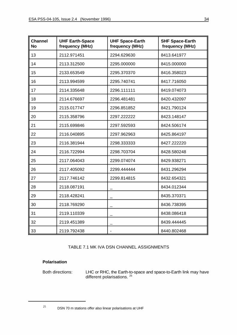
Channel assignments: see Table 7.1
Channel UHF Earth-Space UHF Space-Earth SHF Space-EarthNo frequency (MHz) frequency (MHz) frequency (MHz)
1 _ 2290.185185 -
2 _ 2290.555556 -
3 _ 2290.925926 -
4 _ 2291.296296 -
5 2110.243056 2291.666667 8402.777780
6 2110.584105 2292.037037 8404.135803
7 2110.925154 2292.407407 8405.493826
8 2111.266204 2292.777778 8406.851853
9 2111.607253 2293.148148 8408.209876
10 2111.948303 2293.518519 8409.567903
11 2112.289352 2293.888889 8410.925927
12 2112.630401 2294.259259 8412.282950
ESA PSS-04-105, Issue 2.4 (November 1996) 34
Channel UHF Earth-Space UHF Space-Earth SHF Space-EarthNo frequency (MHz) frequency (MHz) frequency (MHz)
DSN 70 m stations offer also linear polarisations at UHF25
13 2112.971451 2294.629630 8413.641977
14 2113.312500 2295.000000 8415.000000
15 2133.653549 2295.370370 8416.358023
16 2113.994599 2295.740741 8417.716050
17 2114.335648 2296.111111 8419.074073
18 2114.676697 2296.481481 8420.432097
19 2115.017747 2296.851852 8421.790124
20 2115.358796 2297.222222 8423.148147
21 2115.699846 2297.592593 8424.506174
22 2116.040895 2297.962963 8425.864197
23 2116.381944 2298.333333 8427.222220
24 2116.722994 2298.703704 8428.580248
25 2117.064043 2299.074074 8429.938271
26 2117.405092 2299.444444 8431.296294
27 2117.746142 2299.814815 8432.654321
28 2118.087191 _ 8434.012344
29 2118.428241 _ 8435.370371
30 2118.769290 _ 8436.738395
31 2119.110339 _ 8438.086418
32 2119.451389 _ 8439.444445
33 2119.792438 - 8440.802468
TABLE 7.1 MK IVA DSN CHANNEL ASSIGNMENTS
Polarisation
Both directions: LHC or RHC, the Earth-to-space and space-to-Earth link may havedifferent polarisations. 25

ESA PSS-04-105, Issue 2.4 (November 1996) 35
Telemetry
Symbol rates
NRZ-L with subcarrier: 10 s/s - 250 ks/s
SP-L without subcarrier: 125 ks/s - 250 ks/s
Subcarrier: 10 kHz - 1 MHz, squarewave.
For PSK data rates > 500 s/s the subcarrier should be > 45 kHz.
Ranging
Transponder requirements: The DSN ranging system is different in many essentialaspects from the ESA ranging system. For details, JPLdocument 810-5 should be consulted.
7.4 DATA RELAY SATELLITE COMPATIBILITY
Users planning mixed support from data-relay satellites and the ESA network, or planningmissions wholly supported by data-relay satellites, must consult the relevant referencedocuments:
! for NASA TDRSS, the relevant NASA document is STDN 101.2;
! for ESA DRS, the corresponding document is ESA PSS-04-109.

ESA PSS-04-105, Issue 2.4 (November 1996) 36
APPENDIX A
ACRONYMS AND ABBREVIATIONS USED IN THIS STANDARD
BPSK Bi-Phase Shift Keying (= PSK)
BW Bandwidth
CCIR Comité Consultatif International des Radiocommunications
CCSDS Consultative Committee for Space Data Systems
dB Decibel
dBc dB with respect to the unmodulated carrier
DRS Data Relay Satellite
DSN Deep Space Network of NASA
DH Data Handling
EES Earth Exploration Satellite service
EHF Extremely High Frequency (30GHz-300GHz)
EIRP Equivalent Isotropically Radiated Power
ESA European Space Agency
ESTEC European Space Research and Technology Centre, Noordwijk, Netherlands
ESOC European Space Operations Centre, Darmstadt, Germany
FN Footnote in the ITU Radio Regulations
f Ranging tone frequencyt
GHz Gigahertz
G/T Ratio of Antenna Gain to System Noise Temperature
Hz Hertz
ISRO Indian Space Research Organisation
ITU International Telecommunication Union
ITU/BR Radiocommunications Bureau of the ITU
kHz Kilohertz
ks/s kilosymbols per second
km Kilometre
LHC Left Hand Circular
m Metre
MHz Megahertz
ms Millisecond
NASA National Aeronautics and Space Administration (United States)
NASDA Space Development Agency of Japan

ESA PSS-04-105, Issue 2.4 (November 1996) 37
NRZ Non Return to Zero
NRZ-L Non Return to Zero-Level
NRZ-M Non Return to Zero-Mark
OQPSK Offset Quadrature Phase Shift Keying
PCM Pulse Code Modulation
PFD Power Flux Density
PLL Phase Lock Loop
PM Phase Modulation
PSK Phase Shift Keying (in this Standard identical to Phase Reversal Keying)
P&T Post and Telecommunications Administration
QPSK Quadrature Phase Shift Keying
RF Radio Frequency
RHC Right Hand Circular
Rs Symbol rate
RSS Root Square Sum
Rx Receiver
s Second
s/s symbols per second
SFCG Space Frequency Coordination Group
SHF Super High Frequency (3 GHz-30 GHz)
SP-L Split Phase-Level
SO Space Operation service
SR Space Research service
STAB Standards Approval Board for Space Data Communications of ESA
TC Telecommand
TDRSS Tracking and Data Relay Satellite System (NASA)
TM Telemetry
TR Tracking
TTC Telemetry, Tracking and (Tele)Command
Tx Transmitter
UHF Ultra High Frequency (300 MHz-3000 MHz)
UQPSK Unbalanced Quadrature Phase Shift Keying
2B Double-Sided Phaselock Loop Noise BandwidthL
ESA PSS-04-105, Issue 2.4 (November 1996) 38
APPENDIX B
FREQUENCY ASSIGNMENT PROCEDURE
Several factors must be taken into consideration when proceeding to the choice of the mostappropriate frequency bands for a particular mission and subsequently the assignment of discretefrequencies in the selected bands. Such factors are:
! frequency bands allocated to the radiocommunication service into which the mission underconsideration falls;
! required bandwidth versus available bandwidth in the frequency bands that are allocatedto the services;
! special conditions that may be applicable for the use of a frequency band;
! link budget for a particular mission;
! ground support aspects such as availability of general support capability, availability offrequency bands at the most favoured support Earth station(s);
! availability of technology and existing designs for spacecraft equipment in the frequencyband.
Generally, ESA favours a restriction to the minimum number of frequency bands in order to avoiddiversification of investments.
Once the most appropriate frequency band has been selected, the assignment for one or severalfrequencies within this band will be made. The frequency assignment process - because of itsvery complex nature - can be very lengthy, and consequently shall be started as early as possiblein a project.
Step 1: Selection of mission frequency bands
Objective:
To select in accordance with the provisions of the ITU/RR, the frequency band(s) the mission willmost likely use. The step does not yet include the selection of discrete frequencies.
Data:
(To be supplied by the Spacecraft Project to the ESA Frequency Management Office):
! general mission description;
! orbital parameters (general indications are sufficient, such as "geostationary","circular/polar", "highly eccentric with apogee in NorthSouth", together with approximatevalues for apogee, perigee and inclination);

ESA PSS-04-105, Issue 2.4 (November 1996) 39
! ground support options envisaged;
! year of launch and approximate mission lifetime;
! indication of favoured band.
In many cases this request can be made informally, in order to save time in the frequencyassignment process.
Deadline:
During feasibility study phase.
Step 2: Selection of Discrete Frequencies
Objective:
To select, within frequency bands chosen in Step 1, the discrete mission frequencies. This stepwhich is frequently an iterative one, includes the frequency co-ordination with the national radioregulatory authorities concerned and those space agencies with whom ESA has concludedfrequency coordination agreements (NASA, NASDA, ISRO). In exceptional cases it is possibleto assign tentatively alternative frequencies to a mission to choose from in order to keep someflexibility in the spacecraft design and ground support. As soon as the spacecraft design and thedesign of the ground-support baseline are frozen, any alternative frequencies, that weretentatively assigned, shall be released by the project.
Data:
(To be supplied by the Spacecraft Project to the ESA Frequency Management Office.)The form (Annex 1) shall be used for a request for frequency assignment.
Deadline:
During Phase B study.
NOTE: If preferred frequencies have been identified by the project, these may be proposed.However, it cannot be guaranteed that these will be finally assigned.
Step 3: Coordination and Notification of Frequencies with the RadiocommunicationsBureau of the ITU (ITU/BR)
Objective:
To co-ordinate and inscribe the assigned frequencies into the International Frequency List ofITU/BR so that the frequency assignment becomes a formally recognized one vis-à-vis allMember States of the ITU. The procedure to be followed is found in the ITU Radio Regulations(i.e. in the provisions of Art. 11, 13 and 14 and App. 3 and 4).
In very exceptional cases, it may become necessary for a frequency assignment made in Step2 to be modified as an outcome of this international coordination process; however, this possibilityis a very small one and is virtually restricted to geostationary spacecraft.

ESA PSS-04-105, Issue 2.4 (November 1996) 40
Data:
(To be supplied by the Spacecraft Project Office to the ESA Frequency Management Office.)The data required for the notification with ITU/BR shall be supplied in two consecutive steps:! Advance Publication Information to be furnished for a satellite network (ITU/RR/1042 and
App 4)
! Co-ordination and Notification Data (ITU/RR/1060, 1488 and App 3; plus ITU/RR/1611, ifthe band is allocated under the provisions of Art. 14)
Deadline:
Between 5 and 2.5 years before the launch date, at the request of the Head of the FrequencyManagement Office, who will establish the required documentation in co-operation with theproject team.

ESA PSS-04-105, Issue 2.4 (November 1996) 41
ANNEX 1 TO APPENDIX B
REQUEST FOR FREQUENCY ASSIGNMENT
1. GENERAL INFORMATION
1.1 PROJECT NAME:
1.2 CONTACT PERSON (Name and Phone):
1.3 MISSION OBJECTIVES:
1.4 LAUNCH DATE:
1.5 MISSION LIFETIME
2. ORBIT PARAMETERS:
2.1 CATEGORY A
2.1.1 GEOSYNCHRONOUS ORBITS
- Position on GSO: deg E
- Inclination: deg
2.1.2 NON-GEOSYNCHRONOUS ORBITS
- Apogee: km
- Perigee: km
- Inclination: deg
- Argument of Perigee: deg
- Right Ascension of the Ascending Node: deg
- Period: min
2.2 CATEGORY B
Give general trajectory data (including mention of planets, comets or other mission destinations)

ESA PSS-04-105, Issue 2.4 (November 1996) 42
3. EARTH STATION SUPPORT BASELINE
Earth Station Name (N) and Earth - Space Space - Earth RemarksGeographical Location (L)
N:
L:
N:
L:
N:
L:
N:
L:
N:
L:
N:
L:
N:
L:
N:
L:
Table AP/B 3.1
Note: This table is to be used only as a synoptic overview of the Earth station support baseline.Detailed technical data are to be supplied in subsequent Sections/Tables.
Use the following symbols:
Earth - Space: TC: Telecommand onlyRG: Ranging onlyTC/RG: Simultaneous Telecommand and Ranging
Space - Earth: TM: Telemetry onlyRG: Ranging onlyTM/RG: Simultaneous Telemetry and Ranging

ESA PSS-04-105, Issue 2.4 (November 1996) 43
Use several forms for spacecraft requiring more than one frequency.26
The preferred frequency is given as an indication only. There is no guarantee that it can be finally27
assigned to the project.
Use additional sheet(s) if required; particularly if several spacecraft receive antennas are used.28
4 EARTH-SPACE LINK 26
4.1 SELECTED FREQUENCY BAND: _______________ MHz
4.2 PREFERRED FREQUENCY ________ MHz 27
4.3 OCCUPIED BANDWIDTH (Maximum) ________ kHz
4.4 FIXED TURNAROUND FREQUENCY RATIO WITHSPACE/EARTH FREQUENCY REQUIRED? YES/NO
4.5 EARTH STATION TRANSMITTER OUTPUT POWER(see Table AP/B4.1)
4.6 MAXIMUM SPECTRAL POWER DENSITY(see Table AP/B4.1)
4.7 EARTH STATION ANTENNA GAIN DIAGRAM:(Including maximum gain, see Table AP/B4.2)
4.8 SPACECRAFT RECEIVER SYSTEM NOISE TEMPERATURE ________ K
4.9 SPACECRAFT ANTENNA GAIN AND DIAGRAM ________ dBi28

ESA PSS-04-105, Issue 2.4 (November 1996) 44
The maximum power density applied to the input of the antenna shall be expressed in dBW/Hz, averaged over the worst 4 kHz band for RF carrier frequencies29
below 15 GHz, or averaged over the worst 1 MHz band for carrier frequencies above 15 GHz. The value in dBW shall be referred to 1W (0 dBW).
Transmission modes can be telecommand (TC) only, ranging (RG) only or simultaneous telecommand and ranging (TC/RG). Use one line pertransmission mode:
Transmission Modulation TC TC Subcarrier TC RG RG RF Power at Max. Power Mode Scheme Symbol Rate Frequency Modulation Tone Modulation Antenna Input Density
(TC, RG, TC/RG) (ks/s) (kHz) Index Frequency Index (dBW) (dBW/Ref.BW)(rad) (kHz) (rad)
29
Table AP/B 4.1: EARTH-TO-SPACE TRANSMISSION MODES

ESA PSS-04-105, Issue 2.4 (November 1996) 45
Earth Station Antenna Antenna RF Power at Name Gain Diagram Antenna Input
(dBi) (dBW)
Table AP/B 4.2: TRANSMITTING EARTH STATION CHARACTERISTICS

ESA PSS-04-105, Issue 2.4 (November 1996) 46
Use several forms for spacecraft requiring more than one frequency.30
The preferred frequency is given as an indication only. There is no guarantee that it can be finally31
assigned to the project.
Use additional sheet(s) if required; particularly if several spacecraft transmit antennas are used.32
5 SPACE-EARTH LINK 30
5.1 SELECTED FREQUENCY BAND: ________________ MHz
5.2 PREFERRED FREQUENCY: ________ MHz 31
5.3 OCCUPIED BANDWIDTH (Maximum): ________ kHz
5.4 SPACECRAFT TRANSMITTER POWER(see Table AP/B5.1)
5.5 MAXIMUM SPECTRAL POWER DENSITY(see Table AP/B5.2)
5.6 SPACECRAFT ANTENNA GAIN AND DIAGRAM ________ dBi32
5.7 EARTH STATION RECEIVER SYSTEM NOISE TEMPERATURE(see Table AP/B5.2)
5.8 EARTH STATION ANTENNA GAIN DIAGRAM: ________ dB
5.9 SPACE-TO-EARTH TRANSMISSION MODES:

ESA PSS-04-105, Issue 2.4 (November 1996) 47
The maximum power density applied to the input of the antenna shall be expressed in dBW/Hz, averaged over the worst 4 kHz band for RF carrier frequencies33
below 15 GHz, or averaged over the worst 1 MHz band for carrier frequencies above 15 GHz. The value in dBW shall be referred to 1W (0 dBW).
Transmission modes can be telemetry (TM) only, ranging (RG) only or simultaneous telemetry and ranging (TM/RG). Use one line pertransmission mode:
Transmission Modulation TM TM TM RG RG RF Power at Max. Power Mode Scheme Symbol Rate Subcarrier Modulation Tone Modulation Antenna Input Density
(TM, RG, TM/RG) (ks/s) Frequency Index Frequency Index (dBW) (dBW/Ref.BW)(kHz) (rad) (kHz) (rad)
33
Table AP/B 5.1: SPACE-TO-EARTH TRANSMISSION MODES

ESA PSS-04-105, Issue 2.4 (November 1996) 48
Earth Station Antenna Antenna System NoiseName Gain Diagram Temperature
(dBi) (K)
Table AP/B 5.2: RECEIVING EARTH STATION CHARACTERISTICS

PR '82 P
4
P 'E 2
1204
PT '82 E 2
48B2
ESA PSS-04-105, Issue 2.4 (November 1996) 49
APPENDIX C
PROTECTION OF ARIANE RF SYSTEM
C.1 A suggested Conversion Method for Relating Spurious Radiation Received at ArianeVehicle Equipment Bay Antennas to Spurious Emission Requirements on PayloadTransmitters
Assume that of the power produced by the payload transmitters P less than 10% isT
coupled into the vehicle equipment bay via its antennas. The rest of the power is eitherreflected back into the transmitter or escapes via the transparent sections of the fairing. Toevaluate the relationship between the power flux density incident on the vehicle equipmentbay antennas, P, and the power absorbed into the bay P we may make the approximationR
that the antennas have 0 dBi gain.
Therefore
If free space conditions are assumed, the incident power flux density P can be related tothe electric field by:
Therefore the value of P corresponding to a maximum permitted value of E is given byT
For example, for 20 dB µV/m at 435 MHz, the equivalent payload transmitter power is-100 dBm and for 70 dB µV/m at 5690 MHz the equivalent payload transmitter power is-72.3 dBm.
C.2 Operating Constraints
The following requirements shall be met by spacecraft which are to be launched by anAriane 5 vehicle.
The requirements mentioned below have been taken from:A5-SG-1-X-35-ASAI Spécifications Générales de compatibilité Electromagnétique, Ed.3,Révision 1, 11 mai 1995
The spacecraft shall not radiate a narrow-band electrical field at 0.5 m below the boltedinterface exceeding the limit set in table C.1 (including intentional transmission).

ESA PSS-04-105, Issue 2.4 (November 1996) 50
Frequency range Field(dBµV/m)
10 kHz - 420 MHz 100
420 MHz - 480 MHz 35
480 MHz - 2 GHz 100
2 GHz - 5.45 GHz 145
5.450 GHz - 5.825 GHz 70
5.825 GHz - 20 GHz 145
Table C.1: Maximum Radiated Electrical Field at Bolted I/F
A 35dBµV/m level radiated by the spacecraft, in the launch vehicle telecommand receiver420-480MHz band, shall be considered as the worst case of the sum of spurious level overa 100 kHz bandwidth.
The field in the 5.450 - 5.825 MHz band shall be measured in a resolution bandwidth of10 MHz.
There is a restriction on spacecraft transmissions up to 20 s after separation of thespacecraft. Authorization to allow transmission during the countdown phase and/or flightphase and/or at spacecraft separation will be considered on a case-by-case basis.
The spacecraft telemetry frequency band must not overlap the launch vehicle operationalbands:
2203 MHz ± 250 kHz2218 MHz ± 500 kHz2227 MHz ± 500 kHz2206.5 MHz ± 250 kHz2267.5 MHz ± 250 kHz
Flight constraint: during the powered phase of the launch vehicle and up to separation ofthe spacecraft, no telecommand signal can be sent to the spacecraft.

ESA PSS-04-105, Issue 2.4 (November 1996) 51
APPENDIX D
RF INTERFACE CONTROL REQUIREMENTS
D.1 RF INTERFACE CONTROL DOCUMENTS
For each project that intends to use one or more of the ESTRACK stations, two documentsshall be used to control the spacecraft/Earth-station interface. These will be the
! Spacecraft/Earth-station Interface Control Document
! Link Budget Tables
which are specified in more detail in the subsequent subsections.
The first document will be the definitive and formal specification of the RF interface. Thesecond document will be updated regularly to keep track of the development of thespacecraft and Earth station. Hardware interface compatibility will be demonstrated bySpacecraft/Earth-station compatibility tests, documented by the
! Compatibility test plan
! Compatibility tests results
D.2 SPACECRAFT/EARTH-STATION INTERFACE CONTROL DOCUMENT
This document will be the formal interface specification, containing all the relevantparameters describing the interface between the spacecraft and the Earth stations(s).
The first draft of the document shall be prepared in the study phases of the project by theresponsible engineering department in ESA using inputs from the ESA Study or ProjectManager. It will also contain top-level specifications for any new ground systems to bedeveloped for the project.
The document should achieve its final form, and be agreed on by the ESA Project Managerand the duly appointed representative of the Directorate of Operations, when the relevantspacecraft parameters are definitely specified.
From this time on, the document shall be under the control of the Project Manager, whoshall consult the responsible engineering department in ESA before agreeing to changesto any parameters contained in it.
The document shall contain information on the following items:
! Earth stations and time profile of use.
! Configuration of equipment in Earth stations and links to control centre.
! Performances of Earth station (EIRP, G/T, demodulation losses etc. with tolerances).
! Configuration of equipment on board the spacecraft.
! Performances of spacecraft equipment (Transmitter powers, telecommand thresholds,antenna gains, etc. with tolerances).

ESA PSS-04-105, Issue 2.4 (November 1996) 52
! TTC standards applicable and any waivers granted.
! Choice of parameters for the links (i.e. which subsets of the parameters allowed bythe standards are chosen). (PCM data types, bit rates, formats, subcarriers,modulation indices.)
! Operational modes of the spacecraft TTC subsystem. (Combinations of bit rates,subcarriers, formats, indices, etc. Combination of ranging with telecommand ortelemetry.)
Thus the Spacecraft/Ground-network Interface Control Document shall act as a sourcedocument for all data to be used in the preparation of the Link Budget Tables.
D.3 LINK BUDGET TABLES
Link budget tables shall be prepared by the spacecraft project who shall be responsible forthe correct modeling of all aspects of the links between spacecraft and Earth stations.These link budget tables shall be used throughout the course of the project to monitor thequality of the spacecraft /Earth network interface and be subject to verification by theresponsible engineering department in ESA. Although the exact format may vary fromapplication to application, it is of importance that the same terminology and parameters beused. For this purpose, an example link budget output table is provided in Annex 1 hereto.
(a) Separate link budgets should be produced for all different parameter combinations(e.g. different Earth stations, different spacecraft antennas, bit rates).
(b) For a given set of parameters the link budget should be evaluated for the plannedmaximum distance of the spacecraft from the Earth for which these parameters willbe used.
(c) For each parameter entering the link budget, three values should be used:
! The design value D, which is the value of the parameter expected to beachieved under nominal conditions.
! The adverse tolerance A, which is defined as the worst case of a parameterminus the design value in dB. Adverse conditions such as extremetemperatures, extreme voltages, end of life, end of maintenance period, etc.shall be considered. Normally, the adverse tolerance would be the value givenin a design specification.
! The favorable tolerance F, which is defined as the best case of a parameterminus the design value in dB. Best case conditions such as benign environmentbeginning of life, equipment recently maintained, shall be considered. Often thefavorable tolerance, particularly in the design phase of a project, must representan intelligent guess as to how much better the equipment will turn out to be thanthe design value.
(d) From the design value, the adverse and the favorable tolerances, the mean value µand the variance (F ), based on a particular probability density function for eachn
2
parameter should be calculated according to the equations given below: In theabsence of better statistical data on probability density functions, those given in TableD.1 should be used.
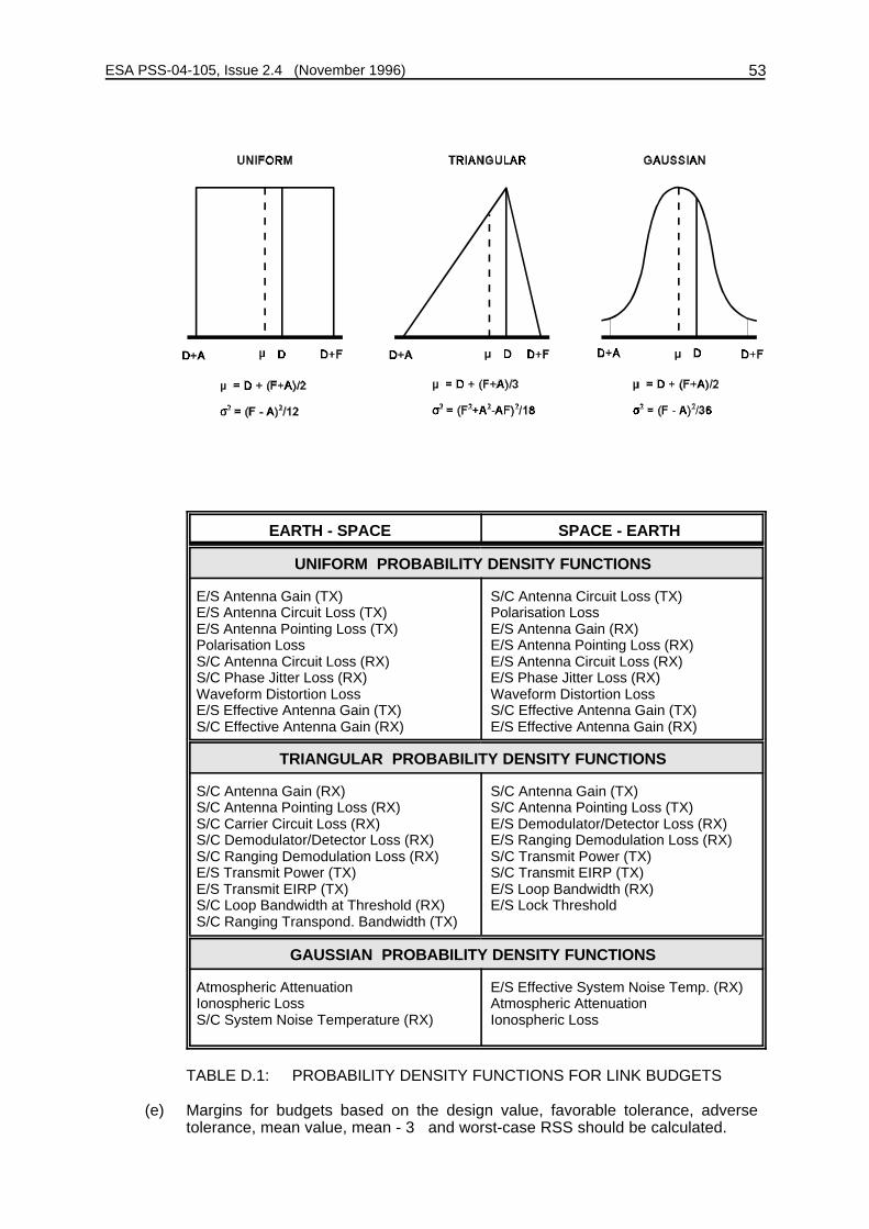
ESA PSS-04-105, Issue 2.4 (November 1996) 53
EARTH - SPACE SPACE - EARTH
UNIFORM PROBABILITY DENSITY FUNCTIONS
E/S Antenna Gain (TX) S/C Antenna Circuit Loss (TX)E/S Antenna Circuit Loss (TX) Polarisation Loss E/S Antenna Pointing Loss (TX) E/S Antenna Gain (RX)Polarisation Loss E/S Antenna Pointing Loss (RX)S/C Antenna Circuit Loss (RX) E/S Antenna Circuit Loss (RX)S/C Phase Jitter Loss (RX) E/S Phase Jitter Loss (RX)Waveform Distortion Loss Waveform Distortion LossE/S Effective Antenna Gain (TX) S/C Effective Antenna Gain (TX)S/C Effective Antenna Gain (RX) E/S Effective Antenna Gain (RX)
TRIANGULAR PROBABILITY DENSITY FUNCTIONS
S/C Antenna Gain (RX) S/C Antenna Gain (TX)S/C Antenna Pointing Loss (RX) S/C Antenna Pointing Loss (TX)S/C Carrier Circuit Loss (RX) E/S Demodulator/Detector Loss (RX)S/C Demodulator/Detector Loss (RX) E/S Ranging Demodulation Loss (RX)S/C Ranging Demodulation Loss (RX) S/C Transmit Power (TX)E/S Transmit Power (TX) S/C Transmit EIRP (TX)E/S Transmit EIRP (TX) E/S Loop Bandwidth (RX)S/C Loop Bandwidth at Threshold (RX) E/S Lock ThresholdS/C Ranging Transpond. Bandwidth (TX)
GAUSSIAN PROBABILITY DENSITY FUNCTIONS
Atmospheric Attenuation E/S Effective System Noise Temp. (RX)Ionospheric Loss Atmospheric AttenuationS/C System Noise Temperature (RX) Ionospheric Loss
TABLE D.1: PROBABILITY DENSITY FUNCTIONS FOR LINK BUDGETS
(e) Margins for budgets based on the design value, favorable tolerance, adversetolerance, mean value, mean - 3F and worst-case RSS should be calculated.

!3 jn
0F2
n
! jn
0
A 2n
ESA PSS-04-105, Issue 2.4 (November 1996) 54
! the margin for mean - 3F is:
margin for mean parameters
! the worst case RSS margin is:
margin for design parameters
(f) Note that the calculation of the variances of the margin from the sum of variancesof its components which have different density functions is valid only if all thevariances are of approximately the same magnitude. If a particular variance isdominant, its statistics must be treated separately.
(g) Unless specified otherwise, the required performance shall be in accordance withthe selected standards:
! for packet telecommand, in accordance with Reference [4].
! for packet telemetry in accordance with Reference [3].
! for ESA standard ranging in accordance with Reference [1].
(h) The jitter performance of the restituted carrier shall be taken into account in thecalculation of the degradation in the demodulation processes.
(i) Each project may choose its own criteria for acceptability of link performance, usingthe various margins calculated in the link budget tables. Experience has shown,however, that margins based on design parameters should exceed 3 dB, and thoseon the RSS worst case and the mean -3F should exceed 0 dB.
(j) The link budget tables should be kept updated during the evolution of the project.In particular, they should reflect new information coming from spacecraft unit,subsystem and system acceptance tests and from spacecraft/ground-networkcompatibility tests.

ESA PSS-04-105, Issue 2.4 (November 1996) 55
D.4 SPACECRAFT/GROUND-NETWORK COMPATIBILITY TEST;
Compatibility of the spacecraft with the ground network shall be demonstrated by meansof compatibility tests. Such tests shall be made on spacecraft TTC equipment andEarth-station equipment to be finally used during the mission. However, where newdevelopments or extensive modifications of existing equipment are involved, preliminarytests should be made in an early phase of the programme using engineering, developmentor even breadboard equipment.
The tests to be performed during compatibility testing will of necessity vary from projectto project. Tests will always aim at establishing thresholds and limiting values so that agood assessment of available margins can be made.
A compatibility test plan, detailing the tests to be performed, the minimum required valuesfor critical parameters, the spacecraft and Earth station equipment to be used etc, will bedrawn up before commencement of the test activities.
At the conclusion of the tests, a Compatibility Test Report will be issued by the responsibleengineering department in ESA. This will contain a formal statement on the compatibilityof the spacecraft and the ground network.
ANNEX 1 TO APPENDIX D
For the purpose of the link budget example below the following equivalent definitions areapplicable:
NOM = DADV = D+AFAV = D+F

P r o j e c t
L I N K I D : X 1 1 1 . 2 P A G E 1 / 4
D A T E : d a t e
O R B I T : Or b i t A L T I T U D E ( 1 0 0 0 k m) : 2 5 5 . 0 0
S T A T I ON : S t a t i o n E L E V A T I ON ( d e g ) : 9 0
T E L E C OMMA N D B I T R A T E ( k b / s e c ) : 2 . 0 0 R A N G I NG : Y e s
T E L E MET R Y B I T R A T E ( k b / s e c ) : 1 . 7 5
R S ( 1 ) o r C O N C A T . C O D I NG ( 2 ) : 2
B A S I C U P L I N K ( 1 / 2 )
NOM A D V F A V ME A N V A R P D F
G/ S T X P OWE R . . . . . . . . . d B W 2 4 . 2 0 2 4 . 0 0 2 4 . 5 0 2 4 . 2 3 0 . 0 1 T R I
C I R C U I T L O S S . . . . . . . . . . d B 0 . 1 0 0 . 2 0 0 . 0 0 0 . 1 0 0 . 0 0 U N I
T X A N T G A I N . . . . . . . . . . d B i 4 7 . 3 0 4 7 . 3 0 4 7 . 3 0 4 7 . 3 0 0 . 0 0 U N I
G/ S A N T T X A X I A L R A T . . d B 0 . 5 0 1 . 0 0 0 . 0 0
P O I N T I NG L OS S . . . . . . . . . d B 0 . 0 5 0 . 1 2 0 . 0 0 0 . 0 6 0 . 0 0 U N I
E I R P G / S . . . . . . . . . . . . . d B W 7 1 . 3 5 7 0 . 9 8 7 1 . 8 0 7 1 . 3 7 0 . 0 2
F R E Q U E N C Y . . . . . . . . . . . . GHz 2 . 0 8 2 . 0 8 2 . 0 8 2 . 0 8
S L A N T R A N G E . . . . . . 1 0 0 0 * k m 2 5 5 . 0 0 2 5 5 . 0 0 2 5 5 . 0 0 2 5 5 . 0 0
P A T H L OS S . . . . . . . . . . . . . d B 2 0 6 . 9 4 2 0 6 . 9 4 2 0 6 . 9 4 2 0 6 . 9 4
A T M O S P H E R I C L O S S . . . . . . d B 0 . 1 0 0 . 2 0 0 . 0 0 0 . 1 0 0 . 0 0 GA U
I O N O S P H E R I C L O S S . . . . . . d B 0 . 0 5 0 . 1 0 0 . 0 0 0 . 0 5 0 . 0 0 GA UCOPOLAR ANT-GAINS(Y=1/N=0)? 1
P O L A R I S A T I ON MI S MA T C H . d B 0 . 0 6 0 . 1 3 0 . 0 0 0 . 0 6 0 . 0 0 U N I
T O T A L P R O P A G . L O S S . . . . d B 2 0 7 . 1 5 2 0 7 . 3 7 2 0 6 . 9 4 2 0 7 . 1 5 0 . 0 0
P O W. - F L U X a t S / C . d Bm/ m^ 2 - 7 7 . 7 7 - 7 8 . 1 4 - 7 7 . 3 2 - 7 7 . 7 5
R X A N T G A I N . . . . . . . . . . d B i - 6 . 0 0 - 6 . 5 0 - 5 . 5 0 - 6 . 0 0 0 . 0 4 T R I
P O I N T I NG L OS S ( * ) . . d B 0 . 0 0 0 . 0 0 0 . 0 0 0 . 0 0 0 . 0 0 T R I
S / C A N T R X A X I A L R A T . . d B 4 . 0 0 4 . 5 0 4 . 0 0
A N T E N N A N O I S E T E MP . . . . . K 4 0 . 0 0 5 0 . 0 0 3 5 . 0 0
A N T E N N A / F E E D V S WR . . . . . : 1 1 . 0 0 1 . 0 0 1 . 0 0
V S WR L OS S . . . . . . . . . . . . . d B 0 . 0 0 0 . 0 0 0 . 0 0 0 . 0 0 0 . 0 0 T R I
C A B L E P H Y S I C A L T E MP. . . . K 2 9 0 . 0 0 3 3 0 . 0 0 2 4 0 . 0 0
C A B L E L O S S . . . . . . . . . . . . d B 0 . 0 0 0 . 0 0 0 . 0 0 0 . 0 0 0 . 0 0 U N I
C I R C U I T S T E M P E R A T U R E . . . K 2 9 0 . 0 0 3 3 0 . 0 0 2 4 0 . 0 0
R F D U C I R C U I T L OS S . . . . . d B 2 . 1 0 2 . 7 0 2 . 1 2 2 . 4 1 0 . 0 3 U N IT O T A L C I R C U I T & C A B L E L O S S . . . . . d B 2 . 1 0 2 . 7 0 2 . 1 2
D I P L . C I R C U I T L O S S . . . . d B 0 . 0 0 0 . 0 0 0 . 0 0 0 . 0 0 0 . 0 0 U N I
R E C E I V E R N O I S E F I G U R E . d B 5 . 0 0 5 . 0 0 5 . 0 0
R E F S Y S T E M T E MP ( * * ) . K 9 1 7 . 0 6 9 1 7 . 0 6 9 1 7 . 0 6
R X S Y S T E M T E MP ( * * * ) . . K 7 6 2 . 9 1 8 0 6 . 6 9 7 4 1 . 2 4
R X S Y S T E M T E MP ( * * * ) d B K 2 8 . 8 2 2 9 . 0 7 2 8 . 7 0 2 8 . 8 8 0 . 0 0 GA U
S / C R X G / T . . . . . . . . . . d B / K - 3 6 . 9 2 - 3 8 . 2 7 - 3 6 . 3 2
R X P O WE R ( * * * ) . . . . . d Bm - 1 1 3 . 9 0 - 1 1 5 . 5 9 - 1 1 2 . 7 6 - 1 1 4 . 1 9 0 . 0 9
T H E O R C A R T H R S H ( * * ) d Bm - 1 2 9 . 9 5
C A R A C Q T H R S H ( * * ) . d Bm - 1 2 8 . 0 0 - 1 2 8 . 0 0 - 1 2 8 . 0 0
T H E O R T C T H R S H ( * * ) . d Bm - 1 1 8 . 0 0
T C R X T H R S H ( * * ) . d Bm - 1 1 7 . 0 0 - 1 1 7 . 0 0 - 1 1 7 . 0 0
R E Q R X P O WE R ( * * * ) . d Bm - 1 1 7 . 0 0 - 1 1 7 . 0 0 - 1 1 7 . 0 0 - 1 1 7 . 0 0
R X P O WE R M A R G I N . . . . . . . d B 3 . 1 0 1 . 4 1 4 . 2 4 2 . 8 1 0 . 0 9
M E A N - 3 * S I GMA. . . . . . . d B 1 . 9 2
MARGI N - w . c . R S S . . d B 2 . 2 8
R X S / N o . . . . . . . . . . . . . d B H z 5 5 . 8 8 5 3 . 9 5 5 7 . 1 4 5 5 . 5 3 0 . 0 9
* ) P O I N T I NG L OS S ma y b e i n c l u d e d i n R X A N T E N N A G A I N .
* * ) R e f e r e n c e a t D i p l e x e r / R F D U I n t e r f a c e , 2 9 0 K i n p u t n o i s e t e mp e r a t u r e .
* * * ) R e f e r e n c e a t D i p l e x e r / R F D U I n t e r f a c e .
ESA PSS-04-105, Issue 2.4 (November 1996) 56

P r o j e c t
L I N K I D : X 1 1 1 . 2 P A G E 2 / 4 D A T E : d a t e
O R B I T : Or b i t A L T I T U D E ( 1 0 0 0 k m) : 2 5 5 . 0 0
S T A T I ON : S t a t i o n E L E V A T I ON ( d e g ) : 9 0
T E L E C OMMA N D B I T R A T E ( k b / s e c ) : 2 . 0 0 R A N G I NG : Y e s
T E L E MET R Y B I T R A T E ( k b / s e c ) : 1 . 7 5 w i t h C O N C A T . CODI NG : Y e s
U P L I N K ( 2 / 2 )
NOM A D V F A V ME A N V A R P D F
R X S / N o . . . . . . . . . . . . . d B H z 5 5 . 8 8 5 3 . 9 5 5 7 . 1 4 5 5 . 5 3 0 . 0 9
MODUL A T I ON I N D I C E S ( * )
T E L E C O MMA N D . . . . . . . r a d p k 1 . 0 0 1 . 0 5 0 . 9 5 ( s i n e )
R A N G I NG ( R N G ) . . . . . r a d p k 0 . 4 0 0 . 4 2 0 . 3 8
RNG, s i n e ( 1 ) o r s q r e ( 2 ) : 1
C A R R I E R R E C O V E R Y
C A R R I E R S U P P R E S S I ON. . . d B 2 . 6 8 2 . 9 7 2 . 4 0 2 . 6 8 0 . 0 1 T R I
B P L ( 1 ) , n o n - c o h A GC ( 2 )
o r c o h e r e n t A G C ( 3 ) ? 3
A G C I N P U T B N D WD T H . . k H z 7 . 9 5 8 . 7 5 7 . 1 6
P L L - B D W 2 * B l o ( * * ) . . . H z 8 0 0 . 0 0 9 6 0 . 0 0 6 4 0 . 0 0
T H R S H D C / N i n 2 * B l o . . . d B 1 0 . 0 0 ( c o mmo n D e f i n i t i o n )
P L L D A MP I NG ( * * ) . . . . . 0 . 7 1 0 . 7 8 0 . 6 4
E f f e c t P L L D A MPI NG. . . . . . 0 . 7 1 0 . 7 8 0 . 6 4
E f f e c t P L L - B D W 2 * B l . . . H z 8 0 0 . 0 0 9 6 0 . 0 0 6 4 0 . 0 0
Ma x A C Q S WE E P R A T E . k H z / s 3 2 . 0 0 2 5 . 5 2 3 2 . 0 0 2 8 . 7 6
E f f e c t P L L - B D W 2 * B l . d B H z 2 9 . 0 3 2 9 . 8 2 2 8 . 0 6 2 8 . 9 7 0 . 1 3 T R I
B P - L I MT S Y S T E M L OS S . . . d B 0 . 0 0 0 . 0 0 0 . 0 0 0 . 0 0 0 . 0 0 T R I
I MPL E M E N T A T I ON L OS S . . . d B 1 . 1 0 1 . 5 0 0 . 8 0 1 . 1 3 0 . 0 2 T R I
R E Q C / N i n P L L - B D W. . . . d B 1 4 . 0 0 1 4 . 0 0 1 4 . 0 0 1 4 . 0 0
C A R R I E R MA R G I N . . . . . . . . d B 9 . 0 7 5 . 6 5 1 1 . 8 8 8 . 7 4 0 . 2 6
M E A N - 3 * S I GMA. . . . . . . d B 7 . 2 3
MARGI N - w . c . R S S . . d B 7 . 8 0
T E L E C O M M A N D R E C O V E R Y
MODUL A T I ON L OS S . . . . . . . d B 4 . 4 7 4 . 8 4 4 . 1 3 4 . 4 8 0 . 0 2 T R I
I MPL ME N T L OS S ( * * * ) . . d B 1 . 5 0 1 . 6 0 1 . 1 0 1 . 4 0 0 . 0 1 T R I
B I T R A T E . . . . . . . . . . . . k b / s 2 . 0 0 2 . 0 0 2 . 0 0
B I T R A T E . . . . . . . . . . . . d B H z 3 3 . 0 1 3 3 . 0 1 3 3 . 0 1 3 3 . 0 1
R E Q E b / N o ( * * * * ) . . d B 1 2 . 0 0 1 2 . 0 0 1 2 . 0 0 1 2 . 0 0
T E L E C O MMA N D MA R G I N . . . . d B 4 . 9 0 2 . 4 9 6 . 9 0 4 . 6 4 0 . 1 2
M E A N - 3 * S I GMA. . . . . . . d B 3 . 5 8
MARGI N - w . c . R S S . . d B 3 . 9 6
T R A N S P D R A N G I NG- C H A N N E L
T C i n RNG- V d b d ? Y = 1 / N = 0 1
T O N E M O D U L A T I ON L O S S . . d B 1 3 . 4 7 1 4 . 1 5 1 2 . 8 2
RNG NOI S E B N D WI D T H . . . k H z 3 0 0 0 . 0 0 3 3 0 0 . 0 0 2 7 0 0 . 0 0
RNG NOI S E B N D WI D T H . . d B H z 6 4 . 7 7 6 5 . 1 9 6 4 . 3 1
I MPL E M E N T A T I ON L OS S . . . d B 1 . 4 6 1 . 6 0 1 . 2 0
S ( T o n e ) / N i n V i d e o b d . . d B - 2 3 . 8 2 - 2 6 . 9 9 - 2 1 . 1 9
S ( T C ) / N i n RG- V i d e o b d . d B - 1 4 . 8 2 - 1 2 . 5 0 - 1 7 . 6 8
* ) A D V a n d F A V C a s e s r e f e r H E R E t o t h e C a r r i e r R e c o v e r y !
V a r i a t i o n o f t h e P r e s e t I n d i c e s i s + / - 5 % .
* * ) R e f e r e n c e a t C a r r i e r A c q u i s i t i o n T h r e s h o l d .
* * * ) D e mo d L o s s u n t i l T C V i d e o Ou t p u t ; T C D e c o d e r L o s s n o t i n c l u d e d .
* * * * ) I n c l u d e s T C D e c o d e r I mp l e me n t a t i o n L o s s e s .
ESA PSS-04-105, Issue 2.4 (November 1996) 57

P r o j e c t
L I N K I D : X 1 1 1 . 2 P A G E 3 / 4 D A T E : d a t e
O R B I T : Or b i t A L T I T U D E ( 1 0 0 0 k m) : 2 5 5 . 0 0
S T A T I ON : S t a t i o n E L E V A T I ON ( d e g ) : 9 0
T E L E C OMMA N D B I T R A T E ( k b / s e c ) : 2 . 0 0 R A N G I NG : Y e s
T E L E MET R Y B I T R A T E ( k b / s e c ) : 1 . 7 5 w i t h C O N C A T . CODI NG : Y e s
B A S I C DOWN L I N K ( 1 / 2 )
NOM A D V F A V ME A N V A R P D F
S / C T X P O WE R . . . . . . . . . d B W 3 . 7 0 3 . 7 0 5 . 7 0 4 . 3 7 0 . 2 2 T R I
D I P L . C I R C U I T L O S S . . . . d B 0 . 1 0 0 . 2 0 0 . 0 0
R F D U C I R C U I T L OS S . . . . . d B 2 . 1 0 2 . 6 0 2 . 0 0
C A B L E L O S S . . . . . . . . . . . . d B 0 . 1 0 0 . 2 0 0 . 0 0
V S WR , o v e r a l l . . . . . . . . . : 1 1 . 0 0 1 . 0 0 1 . 0 0
V S WR L OS S E S . . . . . . . . . . . d B 0 . 0 5 0 . 1 0 0 . 0 0
T O T A L L O S S . . . . . . . . . . . . d B 2 . 3 5 3 . 1 0 2 . 0 0 2 . 5 5 0 . 1 0 U N I
S / C T X A N T G A I N . . . . . . d B i - 6 . 0 0 - 6 . 5 0 - 5 . 5 0 - 6 . 0 0 0 . 0 4 T R I
S / C A N T T X A X I A L R A T . . d B 4 . 0 0 4 . 5 0 4 . 0 0
P O I N T I NG L OS S ( * ) . . d B 0 . 0 0 0 . 0 0 0 . 0 0 0 . 0 0 0 . 0 0 T R I
E I R P S / C . . . . . . . . . . . . . d B W - 4 . 6 5 - 5 . 9 0 - 1 . 8 0 - 4 . 1 8 0 . 3 6
F R E Q U E N C Y . . . . . . . . . . . . GHz 2 . 2 6 2 . 2 6 2 . 2 6 2 . 2 6
S L A N T R A N G E . . . . . . 1 0 0 0 * k m 2 5 5 . 0 0 2 5 5 . 0 0 2 5 5 . 0 0 2 5 5 . 0 0
P A T H L OS S . . . . . . . . . . . . . d B 2 0 7 . 6 5 2 0 7 . 6 5 2 0 7 . 6 5 2 0 7 . 6 5
A T M O S P H E R I C L O S S . . . . . . d B 0 . 1 0 0 . 2 0 0 . 0 0 0 . 1 0 0 . 0 0 GA U
I O N O S P H E R I C L O S S . . . . . . d B 0 . 0 5 0 . 1 0 0 . 0 0 0 . 0 5 0 . 0 0 GA UCOPOLAR ANT-GAINS(Y=1/N=0)? 1
P O L A R I S A T I ON MI S MA T C H . d B 0 . 0 6 0 . 1 3 0 . 0 0 0 . 0 6 0 . 0 0 U N I
T O T A L P R O P A G . L O S S . . . . d B 2 0 7 . 8 6 2 0 8 . 0 8 2 0 7 . 6 5 2 0 7 . 8 7 0 . 0 0
F L U X a t G/ S . . . . . . d Bm/ m^ 2 - 1 5 3 . 7 7 - 1 5 5 . 0 2 - 1 5 0 . 9 2 - 1 5 3 . 3 1 0 . 3 7
P O WE R F L U X D E N S . . d B W/ m^ 2 - 1 8 7 . 5 9 - 1 8 3 . 9 4 - 1 8 9 . 7 6 ( i n 4 k H z )
MA X I M F L U X D E N S . . d B W/ m^ 2 - 1 4 4 . 0 0 - 1 4 4 . 0 0 - 1 4 4 . 0 0 ( S - o r X - B n d )
F L U X M A R G I N . . . . . . . . . . . d B 4 3 . 5 9 3 9 . 9 4 4 5 . 7 6
G/ S R X A N T G A I N . . . . . . d B i 4 8 . 0 0 4 8 . 0 0 4 8 . 0 0 4 8 . 0 0 0 . 0 0 U N I
P O I N T I NG L OS S . . . . . . . . . d B 0 . 0 3 0 . 0 5 0 . 0 0 0 . 0 3 0 . 0 0 U N I
G/ S A N T R X A X I A L R A T . . d B 0 . 5 0 1 . 0 0 0 . 0 0
S Y S T E M NOI S E T E MP. . . . d B K 2 1 . 1 0 2 1 . 4 0 2 0 . 8 0 2 1 . 1 0 0 . 0 1 GA U
R X G / T . . . . . . . . . . . . . . d B / K 2 6 . 9 0 2 6 . 6 0 2 7 . 2 0 2 6 . 9 0 0 . 0 1
R X S / N o . . . . . . . . . . . . . d B H z 4 2 . 9 6 4 1 . 1 7 4 6 . 3 5 4 3 . 4 2 0 . 3 8
S / N i n R A N G I N G B A N D WI D T H
S ( T o n e ) / N i n V i d e o b d . . d B - 2 3 . 8 2 - 2 6 . 9 9 - 2 1 . 1 9
S ( T C ) / N i n RG- V i d e o b d . d B - 1 4 . 8 2 - 1 2 . 5 0 - 1 7 . 6 8
MODUL A T I ON I N D I C E S ( * * )
T E L E ME T R Y ( T M) . . . . r a d p k 1 . 1 3 1 . 2 4 1 . 0 2
T M, s i n e ( 1 ) o r s q r e ( 2 ) : 1
R A N G I NG ( s i n e ) . . . . r a d p k 0 . 6 0 0 . 6 6 0 . 5 4
R A N G . T O N E e f f e c . . r a d p k 0 . 0 4 0 . 0 6 0 . 0 2
T C i n RG- V i d e o b d . . r a d p k 0 . 1 1 0 . 1 5 0 . 0 7
NOI S E I N D E X . . . . . . . . . . . . . 0 . 5 9 0 . 6 5 0 . 5 2
* ) P O I N T I NG L O S S m a y b e i n c l u d e d i n T X A N T E N N A G A I N .
* * ) A D V a n d F A V C a s e s r e f e r H E R E t o t h e C a r r i e r R e c o v e r y !
V a r i a t i o n o f t h e P r e s e t I n d i c e s i s + / - 1 0 % .
ESA PSS-04-105, Issue 2.4 (November 1996) 58

Pr o j e c t
L I NK I D : X1 1 1 . 2 PAGE 4 / 4 DATE : d a t e
ORBI T : Or b i t AL T I TUDE ( 1 0 0 0 k m) : 2 5 5 . 0 0
S T A T I ON : St a t i o n EL E V A T I ON ( d e g ) : 9 0
T E L E C OMMAND BI T R A T E ( k b / s e c ) : 2 . 0 0 RANGI NG : Y e s
T E L E METRY B I T R A T E ( k b / s e c ) : 1 . 7 5 wi t h CONCAT . CODI NG : Y e s
DOWNLI NK ( 2 / 2 )
NOM ADV F A V MEAN VAR PDF
RX S/ No . . . . . . . . . . . . . d B Hz 4 2 . 9 6 4 1 . 1 7 4 6 . 3 5 4 3 . 4 2 0 . 3 8
CARRI ER RECOVERY
CARRI ER SUPPRESSI ON. . . d B 3 . 8 1 4 . 7 3 3 . 0 2 3 . 8 6 0 . 1 2 TRI
PL L BANDWI DT H 2 * B l . . . Hz 3 0 . 0 0 3 6 . 0 0 2 4 . 0 0
PL L BANDWI DTH. . . . . . . d B Hz 1 4 . 7 7 1 5 . 5 6 1 3 . 8 0 1 4 . 7 1 0 . 1 3 TRI
REQ L OOP S / N. . . . . . . . . . d B 1 7 . 0 0 1 7 . 0 0 1 7 . 0 0 1 7 . 0 0
CARRI ER MARGI N. . . . . . . . d B 7 . 3 7 3 . 8 7 1 2 . 5 3 7 . 8 6 0 . 6 3
MEAN- 3 * SI GMA. . . . . . . d B 5 . 4 7
MARGI N - w. c . RSS. . d B 5 . 8 3
T E L E METRY RECOVERY
T L M MODUL A T I ON L OSS. . . d B 4 . 1 6 5 . 0 0 3 . 4 6 4 . 2 1 0 . 1 0 TRI
DEMODUL A T OR TECH L OSS. d B 0 . 5 0 0 . 6 0 0 . 4 0 0 . 5 0 0 . 0 0 TRI
BI T RATE . . . . . . . . . . . . k b / s 1 . 7 5 1 . 7 5 1 . 7 5
BI T RATE . . . . . . . . . . . . d B Hz 3 2 . 4 3 3 2 . 4 3 3 2 . 4 3 3 2 . 4 3
CONCAT C ODI NG GAI N( * ) . d B 9 . 7 0 9 . 7 0 9 . 7 0
CODI NG RAT E 1 / R. . . . . . . . . 2 . 2 9
REQ Eb / No ( P F L = 1 . E - 5 ) . d B 2 . 8 0 2 . 8 0 2 . 8 0 2 . 8 0
T E L E METRY MARGI N. . . . . . d B 3 . 0 7 0 . 3 4 7 . 2 5 3 . 4 9 0 . 4 8
MEAN- 3 * SI GMA. . . . . . . d B 1 . 4 1
MARGI N - w. c . RSS. . d B 1 . 7 9
TONE RECOVERY
TONE MODUL A T I ON L OSS. . d B 3 5 . 2 4 4 0 . 3 3 3 0 . 9 4 3 5 . 6 3
I MPL EMENTATI ON L OSS. . . d B 0 . 0 0 0 . 0 0 0 . 0 0 0 . 0 0
REQ S( T o n e ) / N. . . . . . . . . d B 1 9 . 0 0 1 9 . 0 0 1 9 . 0 0 1 9 . 0 0
MAX REQ L OOP - BDW( * * ) . mHz 7 4 . 5 1 1 5 . 2 7 4 3 7 . 3 6 7 5 . 6 9
COMB . CARR. J I T T E R ( * * * )
RX TRSPD- P L L J I T T . . . d e g 2 . 8 4 4 . 2 2 2 . 0 6 2 . 9 6
TRANSMT CARR. J I T T . . . d e g 2.00 3 . 0 0 1 . 0 0 2 . 0 0J I T T B D W 2 * B ( * * * * ) . . . Hz 5 . 0 0 1 0 . 0 0 3 . 0 0 6 . 5 0
RX COMBD CARR J I T T . . . d e g 3 . 9 3 5 . 9 3 2 . 5 7 4 . 1 6
* ) P F L = P r o b a b i l i t y o f F r a me L o s s . T r a n s f e r F r a me L e n g t h
i s F S = 1 2 7 5 Oc t e t s , a n d I n t e r l e a v i n g De p t h i s I = 5 .
* * ) T h e r e q u i r e d MI NI MUM L o o p - Ba n d wi t h s u p p o r t e d b y MP T S i s 1 . 2 5 mHz ;
t h e MAXI MUM L o o p - Ba n d wi d t h ( t wo - s i d e d ) i s 1 8 8 0 mHz .
* * * ) Co h e r e n t t r a n s p o n d e r mo d e a s s u me d f o r RX COMBD CARR J I T T e r a t G/ S .
* * * * ) 2 * B i s t h e b a n d wi d t h o f t h e j i t t e r f r o m t h e T X c h a i n o r a HPA.
ESA PSS-04-105, Issue 2.4 (November 1996) 59

ESA PSS-04-105, Issue 2.4 (November 1996) 60