radio frequency (rf)-based, real-time, indoor localization
TRANSCRIPT

Acta Polytechnica Hungarica Vol. 17, No. 9, 2020
– 19 –
Radio Frequency (RF)-based, Real-Time,
Indoor Localization System for Unmanned
Aerial Vehicles and Mobile Robot Applications
Sándor Tihamér Brassai, István Zsolt Székely
Sapientia Hungarian University of Transylvania, Department of Electrical
Engineering, Corunca 1.C, 540485, Romania, e-mail: [email protected],
Abstract: The goal of this paper is to describe the indoor localization of a moving object,
such as, an UAV or mobile robot, in real time. For localization, the triangulation method is
used, based on a multiple fixed points anchors. The distance measurement between the
moving object and the anchors is realized with DWM1000 UWB compliant, wireless
transceiver modules. For distance measurement, the double-sided, two-way ranging
method is used. The position is revealed after the triangulation is corrected, based on the
Kalman filter. This computationally intensive task is running on FPGA and provides a real-
time operation. One of the anchors is connected to FPGA with a serial communication
interface. For the triangulation and Kalman filter, hardware module generation high level
synthesis, is used. In the paper, in addition to the implementation, measurement results are
also presented for real-time localization.
Keywords: Indoor localization; FPGA; High level synthesis; Kalman filter
1 Introduction
Indoor localization is a timely, active research area, with more challenges to be
solved. More and more indoor applications require precise localization: mobile
vehicle applications in factories and mines, healthcare applications [1], [2], fitness
monitoring, assisted living [3], technical lab applications, games and
entertainment, building automation [4] [5].
The reliability, required accuracy and response time, determine the selection of a
solution/technology for the indoor localization implementation. The indoor
positioning technologies can be grouped in several categories: wave propagation,
image based and inertial navigation-based localization [5].
Other researchers categorize the indoor positioning technologies based on the kind
of the signal used for object position determination: Radio Frequency Signals

S. T. Brassai et al. Radio Frequency (RF)-based, Real-Time, Indoor Localization System for Unmanned Aerial Vehicles and Mobile Robot Applications
– 20 –
(RF), light, sound, audible and ultrasonic respective magnetic field-based
solutions [6]. A wide variety of RF signal localization systems are known like Wi-
Fi, Bluetooth, ZigBee, RFID Ultra-Wideband. UWB technology presents some
advantages in indoor positioning such as precision of time-of-flight measurement,
multipath immunity and low power requirements [7] [8] [9].
Based on multiple reference devices, of which location is known, the position of
the device attached to the moving object can be calculated. For distance estimation
a variety of measurements can be used such as Received Signal Strength (RSS)
[10] [11], Time of Arrival (ToA), Time Difference of Arrival (TDoA), and Angle
of Arrival (AoA) [12].
Localization of moving objects in real time is a challenge, complex calculations
are required. The emphasis and novelty of the paper is the acceleration of
calculations of localization algorithm on the FPGA circuit. Critical parts of the
real time localization process, for which calculations must be performed in a short
period of time, such as triangulation, pre-filtering and the Kalman Filter, are
modeled and implemented in hardware. For the future, the aim is to integrate into
a single system the indoor localization methods, UAV systems [13] [14] and
mobile robots [15] [16] [17], enabling mobile robots and UAV systems to be used
for special indoors or even outdoors applications.
In this paper the chosen methods, algorithms, and their implementation are
discussed. The paper is divided into six subsections followed by the conclusions,
which summarize the results obtained. The indoor localization background is
presented in section two. Theoretical background of the triangulation method and
Kalman filter is detailed in the third and fourth sections. The fifth part describes
the triangulation and Kalman filtering algorithms implemented on FPGA as well
as the stand used to carry out measurements. The sixth section summarizes the
results of the localization obtained with simulations and real measurements under
laboratory conditions.
2 Indoor Localization Background
The project’s aim is the development of a positioning system, used to locate the
robot’s position in real time.
There are many different localization systems and technologies which can be used
for measuring an objects position. Each of these systems have their own
advantages and disadvantages. Recent articles point out different aspects and
applications of these, like, accuracy, energy efficiency, scalability, cost and such
[18]. The goal was to use a system which is accurate and energy efficient, as well
as it doesn’t require any special or additional equipment. Recently UWB (ultra-
wideband modules) have become popular in localization, because of low energy

Acta Polytechnica Hungarica Vol. 17, No. 9, 2020
– 21 –
consumption and accuracy. Using such modules, there were different attempts to
develop better indoor localization systems, for either better accuracy or multiple
tags, since these algorithms mostly rely on message transmission [19] [20]. The
goal is to achieve an accurate position measurement using few moving objects, so
an adequate hardware and algorithm are used and implemented.
The system using the triangulation technique measures the distance to different
anchored points. For the distance measurement, DWM 1000 ultra-wide-band
modules based on radio frequency were used. To improve the resulting position,
after triangulation, a filtering algorithm is applied, to achieve a better estimation
of the objects position. Both the triangulation and the filter algorithms are running
in parallel on the FPGA.
Figure 1
Essential connections
The RF modules used here, for the distance measurement, are a dedicated
hardware, DWM1000, developed by DecaWave. The devices implied in position
determination, are separated in two categories (Figure 1). In the first group there
are the those with known and fixed positions and in the second group are the ones,
in which the position has to be computed. These modules are deployed in the
field, at least three in fixed positions and at least one is attached to the moving
object, of which, the position has to be calculated.
The device controlling the RF modules, is an ESP8266 microcontroller. There is a
written and working program library, for the measurements, which was rewritten
according to the project’s goals.
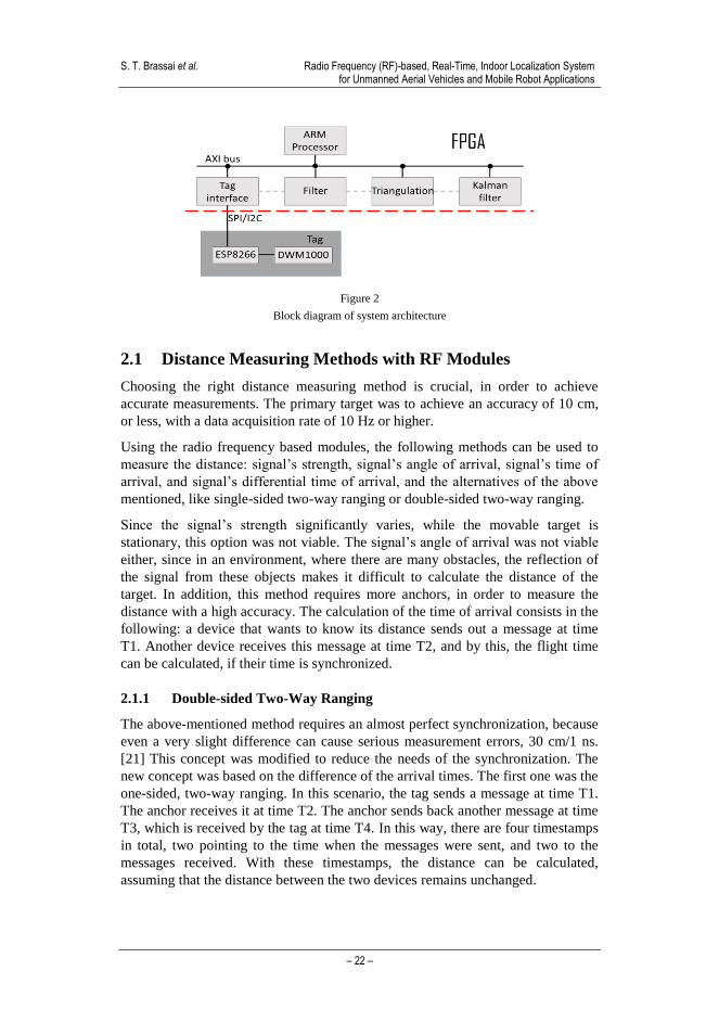
In the case of the moving target, of which, the position has to be measured, the
ESP module is attached to the FPGA on SPI protocol (Figure 2). After measuring
the distances, for noise reduction, a filter algorithm is used and then the location is
computed using the triangulation method. The newly acquired location is
optimized with a Kalman-filter. The filtering algorithms are also implemented in
the FPGA circuit.
S. T. Brassai et al. Radio Frequency (RF)-based, Real-Time, Indoor Localization System for Unmanned Aerial Vehicles and Mobile Robot Applications
– 22 –
Figure 2
Block diagram of system architecture
2.1 Distance Measuring Methods with RF Modules
Choosing the right distance measuring method is crucial, in order to achieve
accurate measurements. The primary target was to achieve an accuracy of 10 cm,
or less, with a data acquisition rate of 10 Hz or higher.
Using the radio frequency based modules, the following methods can be used to
measure the distance: signal’s strength, signal’s angle of arrival, signal’s time of
arrival, and signal’s differential time of arrival, and the alternatives of the above
mentioned, like single-sided two-way ranging or double-sided two-way ranging.
Since the signal’s strength significantly varies, while the movable target is
stationary, this option was not viable. The signal’s angle of arrival was not viable
either, since in an environment, where there are many obstacles, the reflection of
the signal from these objects makes it difficult to calculate the distance of the
target. In addition, this method requires more anchors, in order to measure the
distance with a high accuracy. The calculation of the time of arrival consists in the
following: a device that wants to know its distance sends out a message at time
T1. Another device receives this message at time T2, and by this, the flight time
can be calculated, if their time is synchronized.
2.1.1 Double-sided Two-Way Ranging
The above-mentioned method requires an almost perfect synchronization, because
even a very slight difference can cause serious measurement errors, 30 cm/1 ns.
[21] This concept was modified to reduce the needs of the synchronization. The
new concept was based on the difference of the arrival times. The first one was the
one-sided, two-way ranging. In this scenario, the tag sends a message at time T1.
The anchor receives it at time T2. The anchor sends back another message at time
T3, which is received by the tag at time T4. In this way, there are four timestamps
in total, two pointing to the time when the messages were sent, and two to the
messages received. With these timestamps, the distance can be calculated,
assuming that the distance between the two devices remains unchanged.

Acta Polytechnica Hungarica Vol. 17, No. 9, 2020
– 23 –
𝑡𝑜𝑓 =(𝑡4−𝑡3)−(𝑡2−𝑡1)
2 (1)
This was much better than the previous method, but still wasn’t enough, so it was
further developed. This method is called double-sided two-way ranging. This one
is improved compared to the previous one by inserting an additional message,
with this there are 6 timestamps in total, with which the distance can be measured
[22].
𝑡𝑜𝑓 =(𝑡4−𝑡1)∗(𝑡6−𝑡3)−(𝑡3−𝑡2)∗(𝑡5−𝑡4)
(𝑡4−𝑡1)+(𝑡6−𝑡3)+(𝑡3−𝑡2)+(𝑡5−𝑡4) (2)
There is a drawback, when more messages are exchanged, the accuracy
improvement is less and less and when using multiple messages for range
calculation, the accuracy can be even worse, if the target is moving [21].
2.2 Measuring Distance with an Anchor and a Tag
In the program library an example application of double-sided two-way ranging
between two modules was written already. The tag is initiating the distance
measurement by sending a poll message, the anchor receives the message,
acknowledges it, after which the tag sends all the necessary timestamps for the
calculation of the distance. After that the anchor sends back a message with the
calculated distance and both sides know the result. This example had a small
problem, which appeared in the interruption of the communication after random
amounts of time, so it was corrected accordingly.
2.2.1 Results Achieved by Others
The DecaWave manufacturer states that the used DWM1000 modules, can
achieve an accuracy of 10 cm indoors [23]. Most of the users of this module
achieved an accuracy of 5 cm; in some cases, they even achieved 2 cm.
Examining the measured and the real distances, it is clear that every module has
an offset which is usually between 20 to 30 cm. One of the best measurements
others have achieved was with a 23.6 cm offset and a 2 cm standard deviation.
There were cases, where the measurements were quite diverse.
This time they realized that the configuration used for the distance measurement
was affecting it greatly, since these modules have different options for different
use-cases. From measurement results presented in other works can be seen that at
close range, and/or having different objects in the environment between the two
modules, different distance values will be measured (Table 1).

S. T. Brassai et al. Radio Frequency (RF)-based, Real-Time, Indoor Localization System for Unmanned Aerial Vehicles and Mobile Robot Applications
– 24 –
Table 1
Test results provided by Steven (https://github.com/thotro/24ocaliz-dw1000/issues/205)
Real distance
[cm]
Measured
distance [cm]
Average
error [cm]
Standard
deviation
[cm]
25 18.2 -6.8 2.030
50 42.1 -7.9 1.901
100 101.4 1.4 2.063
150 161.2 11.2 1.454
2.2.2 Results
There were varied results acquired during the measurements. The settings of the
modules and the environment in which the measurements were made, affected the
results. These modules can be configured for a certain goal. The performance of
the module was set to the maximum, which means that the data rate and pulse
frequency is set to the highest level. The maximum range was also reduced, at
which the measured distance was reduced. Different measurement results showed
that the modules needed calibration.
Figure 3
Test results: real distance 2.5 m, offset 50 cm, deviation 5 cm, Test results: real distance 10 m, offset
60 cm, deviation 5 cm
When only one anchor and one tag was used, the offset was usually around 40 cm.
The deviations of our measurements were not greater than 10 cm (Figure 3). It has
to be mentioned, that in case of measurement with multiple anchors, the accuracy
decreases and problems occur in the communication between the modules
presenting in the random shutdown of communications.
3 Triangulation Method
The triangulation method is used to find the position of a target, typically in a two-
or three-dimensional space. The method is based on at least three points (positions
are known) and with the distance of the target to these points, the device’s exact

Acta Polytechnica Hungarica Vol. 17, No. 9, 2020
– 25 –
position can be calculated. For example, if the chosen space, where the positioning
is used is two-dimensional, with one fixed point, a circle around the anchor, on
which the target might be, can be determined. By using another fixed point, the
section of the two circles give two points, where the target can be. If the exact
position is needed, and both options are acceptable, then another anchor is needed.
By this, another one of the points is eliminated, and the position of the device is
exact. In three-dimensional space, it is slightly different. The only difference
between the triangulation in two- or three-dimensional space is that the distance
calculated results in a sphere. If two spheres are intersected, then they will provide
a circle, which is similar to the previous one. By this, it can be said that increasing
by one the number of dimensions results in an increase by one of the necessary
fixed points to calculate the exact position. With this method, generally, in an N
dimensional space, N+1 reference points are needed. If the triangulation method is
used in a three-dimensional space, and all the reference points are on the lowest
possible position, then the only position, where the unknown device’s location can
theoretically be, is somewhere above the plane created by the anchors. In this
case, the second point is automatically discarded. If the device can be on both
sides of the plane, N amount of reference points will not be enough. If four
anchors are used in space, then another question must be taken into consideration.
If all four anchors are on the same plane, then the exact position cannot be
calculated, because the exact position is still unknown, since there are two
possible positions. If the four anchors are not on the same plane, then one option
of the two possible positions is going to be removed, since the distance of the
fourth anchor is not the same for the two, it will match only one.
It is considered that there are k amounts of anchors in which the position is
known. These coordinates are (x, y, z). s is the tag’s position, which is unknown,
and its coordinates are (x, y, z). The distance to the anchors can be calculated with
the following formula:
𝑡i = √(xi − 𝑥)2 + (yi − 𝑦)2 + (zi − 𝑧)2 (3)
In this formula there are three unknown values, where result cannot be calculated
so easily, using analytic methods. Every measurement has an error, which has to
be taken into account. Because of this, it is divided into two parts: the real value,
and the error.
𝑡i = 𝑠i(𝑥, 𝑦, 𝑧) + 𝜀(𝑥, 𝑦, 𝑧) (4)
The error is calculated so the evaluation can be corrected. In order to reduce the
error, an iterative method is used.
𝑠i(𝑥, 𝑦, 𝑧) = 𝑠i(�̃� + Δ𝑥, �̃� + Δ𝑦, �̃� + Δ𝑧) (5)
In order to reach the lowest possible error, linear evaluation is used, which
consists in the following steps: in the first stage, each error value is defined.

S. T. Brassai et al. Radio Frequency (RF)-based, Real-Time, Indoor Localization System for Unmanned Aerial Vehicles and Mobile Robot Applications
– 26 –
𝑠i(�̃� + Δ𝑥, �̃� + Δ𝑦, �̃� + Δ𝑧) = 𝑠i(�̃�, �̃�, �̃�) +∂𝑠i
∂𝑥Δ𝑥 +
∂𝑠i
∂𝑦Δ𝑦 +
∂𝑠i
∂𝑧Δ𝑧 (6)
After this, the partial derivatives are calculated.
∂𝑠i
∂𝑥=
−xi+𝑥
√(xi−𝑥)2+(yi−𝑦)2+(zi−𝑧)2= 𝑎i (7)
∂𝑠i
∂�̃�=
−yi+�̃�
√(xi−𝑥)2+(yi−𝑦)2+(zi−𝑧)2= 𝑏i (8)
∂𝑠i
∂𝑧=
−zi+𝑧
√(xi−𝑥)2+(yi−𝑦)2+(zi−𝑧)2= 𝑐i (9)
Having them renamed is easier to use in the future.
𝑠i(�̃� + Δ𝑥, �̃� + Δ𝑦, �̃� + Δ𝑧) = si(�̃�, �̃�, �̃�) + 𝑎iΔ𝑥 + 𝑏iΔ𝑦 + 𝑐iΔ𝑧 (10)
From the equation the evaluated part was removed and vector remains for each
anchor, holding the errors.
Δ𝑠i = 𝑎iΔ𝑥 + 𝑏iΔ𝑦 + 𝑐iΔ𝑧 (11)
The error is calculated using the measured and the evaluated distances difference.
The evaluated distance can be measured using the formula (1).
Δ𝑠i = 𝑠i − �̃�i (12)
After this, the formula (11) is rewritten into a matrix form, where the error vector
Δ … is b, the partial derivatives’ values 𝑎i, 𝑏i, 𝑐i go into matrix A, and the
Δ𝑥, Δ𝑦, Δ𝑧 vector to g. Vector g results are used to correct the evaluated position.
𝒃 = 𝑨𝒈 (13)
Calculating g from the formula above results in the following equation:
𝒈 = 𝑨−1𝒃 (14)
In many cases, the system is overdetermined, and because of this, the least square
algorithm is used. First, the residual vector is calculated.
𝒓 = 𝒃 − 𝑨𝒈 (15)
Its Euclidean square is used in order to be able to calculate vector g.
‖𝒓‖2 = 𝒓T𝒓 = (𝒃 − 𝑨𝒈)T(𝒃 − 𝑨𝒈) (16)
‖𝒓‖2 = 𝒃T𝒃 − 2𝒈T𝑨T𝒃 + 𝒈T𝑨T𝑨𝒈 (17)
The result is equal to zero, and after that, g is placed on one side and the rest to the
other.
−2𝒈T𝑨T𝒃 + 𝒈T𝑨T𝑨𝒈 = 0 (18)
From the resulted equation, the 𝒃T𝒃 is removed, because the equation’s derivative
was used.

Acta Polytechnica Hungarica Vol. 17, No. 9, 2020
– 27 –
𝒈 = (𝑨T𝑨)−1𝑨T𝒃 (19)
Finally, at this point, the vector g is calculated, and the evaluated coordinates can
be improved.
𝒔 = 𝒔 + 𝒈 (20)
This is an iterative method, so it is necessary to do this multiple times, until an
error limit is reached, which is given by the user.
It is important to determine the application itself, the possibilities of placing the
modules, and by this choosing the number of the reference points [24], [25]. The
triangulation method was implemented in the FPGA, because the ESP8266
microcontroller couldn’t calculate the position in time.
4 Kalman Filter
The Kalman filter is a linear quadratic estimator which can provide an accurate
estimation of states. Kalman filters are typically used for linear systems having
Gaussian noise. This filter can estimate states from the data provided by multiple
sensors, which measurements are noisy. The Kalman filter doesn’t have to store
older data values. Kalman filters have relatively simple form and require relatively
small computational power. There are two matrices, the covariance matrix of
measurement noise (Q) and the covariance of the observation noise (R), which are
responsible for the estimation. The Q with dimension 9x9 and R 3x3 was
initialized with identity matrix multiplied by constant values initialized form the
Simulink. In choosing these Q and R parameter values, their ratio matters. With a
Q/R ratio of 1 for example, the estimated values change slowly, neglecting most
of the noise, in case of slower systems. When the ratio is 10, the estimated values
change fast but with less noise suppression [26].
Position prediction based on the transition model:
𝒙k/k-1 = 𝜱k/k-1 𝒙k-1 (21)
𝑷k/k-1 = 𝜱k/k-1 Pk-1𝜱k/k-1T + 𝐐k-1 (22)
�̂�k/k-1 = 𝐇k 𝒙k-1 (23)
Update steps
𝒛k = [𝑥k, 𝑦k, 𝑧k]T (24)
𝜺k =zk-�̂�k/k-1 (25)
𝒙k =𝒙k-1 + 𝑲k−1𝜺k−1 (26)

S. T. Brassai et al. Radio Frequency (RF)-based, Real-Time, Indoor Localization System for Unmanned Aerial Vehicles and Mobile Robot Applications
– 28 –
𝑹k = Rk-1 + 𝜺k𝜺kT − 𝐇k𝑷k𝐇k
T (27)
𝑲k =Pk/k-1𝐇kT[𝐇k𝑷k𝐇k
T + 𝑹k]−1
(28)
𝑷k = (I-𝑲k𝐇k) Pk/k-1(I-𝑲k𝐇k)T
+ 𝑲k𝑹k𝑲kT (29)
𝚽 =
[ 1 T T2/2 0 0 0 0 0 00 1 T 0 0 0 0 0 00 0 1 0 0 0 0 0 00 0 0 1 T T2/2 0 0 00 0 0 0 1 T 0 0 00 0 0 0 0 1 0 0 00 0 0 0 0 0 1 T T2/20 0 0 0 0 0 0 1 T0 0 0 0 0 0 0 0 1 ]
(29)
Where xk is the state variables, k system matrix, Hk the observation model, zk the
measured positions, Kk Kalman gain, Qk the covariance of the measurement noise,
Rk the covariance of the observation noise, Pk estimate covariance matrix, k-error
between the measured and estimated positions. Finally, the estimated positions are
obtained from [x(1) x(4) x(7)].
Transition model is defined based on the motion equation along the coordinates
eq. (29).
5 Implementation
5.1 Distance Measurements between Tags and Anchors
For distance measurement between tag and anchors the double sided two-way
ranging measurement was used (Figure 4).
Figure 4
Double sided two-way ranging signal exchange between a tag and anchor

Acta Polytechnica Hungarica Vol. 17, No. 9, 2020
– 29 –
Figure 5
Double sided two-way ranging signal exchange between a tag and multiple anchors
By using multiple anchors, the communication between the tag and the anchors
was modified, in order to achieve a faster distance measurement. In this case, the
tag has sent one message to all of the anchors. After this, the anchors sent an
answer for the polling message. These anchors sent the message one after another
after a certain amount of time. After the tag received the messages from all the
anchors, it sent another message containing the timestamps necessary to calculate
the distance. After all the anchors received the message, each one calculates the
distance, and sends back the results to the tag (Figure 5).
5.2 Triangulation Method Implementation
The triangulation hardware module was designed with high level synthesis in
Vivado HLS environment. The function, from which the hardware module is
generated, receives the position of the anchor devices as well as the distances to
the fixed devices as inputs and provides the position of the device to be localized
as output argument.
The positions of the fixed devices are stored in an array from which the
triangulation module reads the values of the positions at the beginning of the
calculation cycle. In the current configuration, the devices are spaced 2 m, 2 m
and 2 m along the X, Y and Z axes relative to the origin, and in the first phase of
development were hardware coded, which meant many limitations during the
tests. During the research we have modified many important parameters that can
be given as inputs to the module.
The input and output arrays are partitioned to elementary signals. In addition to
the output positions, the ap_valid protocol signals help synchronize the data
transfer between the triangulation module and Kalman filter. The module's
hardware resource requirements are summarized in Table 2.

S. T. Brassai et al. Radio Frequency (RF)-based, Real-Time, Indoor Localization System for Unmanned Aerial Vehicles and Mobile Robot Applications
– 30 –
Table 2
Triangulation module hardware resource requirements
Name BRAM_18K DSP48E FF LUT
DSP - - - -
Expression - - 0 1822
FIFO - - - -
Instance 2 22 5450 8853
Memory 4 - 192 24
Multiplexer - - - 1082
Register - - 1718 -
Total 6 22 7360 11781
Available 120 80 35200 17600
Utilization (%) 5 27 20 66
5.3 Kalman Filter Implementation
The hardware for the Kalman filter algorithm was also generated by HLS
synthesis. The function receives as input an array of X, Y, Z positions after the
triangulation and also provides the estimated position coordinates in an array.
As for initial estimated values, a position of [0 0 0] is chosen for the tag, which is
equivalent the Origin of the triangulation system. At the beginning, some time is
necessary for the Kalman filter to reach the position of the real system. In this
transitional state, the mobile system should be stationary.
Table 3
Kalman filter module hardware resource requirements
Name BRAM_18K DSP48E FF LUT
DSP - - - -
Expression - - 0 180
FIFO - - - -
Instance 2 14 3043 4748
Memory 16 - 0 0
Multiplexer - - - 1474
Register - - 98 -
Total 18 14 3141 6402
Available 120 80 35200 17600
Utilization (%) 15 17 8 36
HLS_ARRAY_PARTITION forces the input and output arrays to be partitioned
in hardware modules into individual inputs and outputs. In addition to the output
filtered positions, the ap_valid protocol signal helps synchronize signal

Acta Polytechnica Hungarica Vol. 17, No. 9, 2020
– 31 –
transmission between modules. The Kalman filter hardware resource requirements
are summarized in Table 3.
Summing the hardware resources of triangulation and Kalman filter modules
exceed the available hardware resources of Zynq XC7Z010, hardware resources
are optimized during synthesis (Figure 6).
Figure 6
Full localization module hardware resource requirements
5.4 One Degree of Freedom Arm for Tag Movement
In order to test the localization system, measurements were made by mounting the
moving device on a single-degree arm. The synchronization of the signals of the
two measuring systems is easy to implement because both systems are integrated
in the same FPGA circuit. Based on the position of the robotic arm and the
estimated positions returned from the FPGA to the computer, the two
measurements can be easily fitted.
The single-degree servo control loop consists of a cascade P and PID controller, a
PWM signal generator, an H-bridge control circuit, and an encoder for decoding
the servo angular position. The PWM signal generator, encoder and PID control
are also implemented in FPGA circuits and are not described in detail since they
are not present as the basis of the present research.
5.5 Complementary Modules used for Tag Movement
For measurements, the triangulation, Kalman Filter and single-degree positioning
control modules are connected in the Xilinx System Generator (SG). Hardware
co-simulation helped greatly in setting the correct parameters for the subunits and
in developing a functional localization system. In the SG a multiple clock type
system has been developed.
The data exchange over JTAG between the PC and the FPGA is synchronized to
the clock signal of the JTAG interface, while the clock of the modules
implemented in the FPGA is derived from the FPGA master clock.

S. T. Brassai et al. Radio Frequency (RF)-based, Real-Time, Indoor Localization System for Unmanned Aerial Vehicles and Mobile Robot Applications
– 32 –
During the implementation of the hardware co-simulation-based design for the
development board used, to derive the clock from the board master clock special
attention must be paid.
Figure 7
Hardware co-simulation system modules
set_property -dict { PACKAGE_PIN K17 IOSTANDARD LVCMOS33 }
[get_ports { sys_clock }];
create_clock -add -name sys_clk_pin -period 10.00 -waveform {0 5} [get_ports {
sys_clock }];
For the communication between the ESP and the FPGA a hardware implemented
SPI protocol is used. The slave SPI, running in the FPGA, saves the distances in
its own registers, which serve as inputs to the triangulation module.
The following diagram shows the connection of the modules.
Modules are parameterized from the Simulink model via the JTAG interface and
partial results from the modules are also displayed or saved from the Simulink
model.
The triangulation and Kalman Filter modules are exported from the Vivado HLS
environment. The reference model, applied to the Kalman filter, based on which
position estimation is realized, describes the motion equations along the three
axes.
Based on the developed and tested model, an IP core is generated, which is fitted
to the bus system of the FPGA based control unit of mobile robot and UAV.

Acta Polytechnica Hungarica Vol. 17, No. 9, 2020
– 33 –
6 Measurement Results
6.1 Test Results: Simulated –Inputs - Simulated Processing
Depending on how many anchors are used, and which are the starting evaluated
positions, different results were achieved. The calculations were made, while the
device was stationary. First, four anchors were used (Figure 8), which were not
located on a single plane. Different starting values were used, and the results were
all the same. The data used for calculating the position was real.
Figure 8
The result of the positioning using: four anchors, varying starting evaluated values; three anchors,
starting evaluated values initialized with positive values; three anchors, starting evaluated values
initialized with negative values
When three anchors were used (Figure 8) different starting evaluated values gave
different results, using the same measurements as previously with four anchors.
When positive values were used, then the evaluation was similar when measuring
with four anchors.
Figure 9
Result for triangulation method, which is running on the hardware module simulated on Simulink SG
However, when the starting evaluated values were negative, the triangulation
method localizes the device on the other side of the plane, which is formed by the
three anchors.
On Figure 9 a simulation is presented with generated data from Simulink. Multiple
sine waves were generated with different parameters as distances in order to
achieve these coordinates. On the first figure are the calculated coordinates
received from the simulated hardware (Figure 10).

S. T. Brassai et al. Radio Frequency (RF)-based, Real-Time, Indoor Localization System for Unmanned Aerial Vehicles and Mobile Robot Applications
– 34 –
For the Kalman filter testing, the same coordinates were used as in the
triangulation methods testing. In the following two figures the Q and R ratio was
changed in order to see their accuracy and speed of convergence (Figure 10).
Figure 10
The results received from the hardware model simulated in Simulink SG. Results for triangulation, and
Kalman estimation with two different parameter sets of R and Q.
6.2 Test Results: Simulated Inputs - Hardware Processing
The following measurements show the results obtained by testing the triangulation
and Kalman filter modules. The calculations were running on the FPGA circuit.
The inputs from the Simulink environment were generated, according to a real
task. Using a cylindrical, two-degree of freedom robotic arm, the input points
were generated, from which the distances to the anchors were calculated. The
calculated distances, to illustrate the real circumstance, were perturbed with a
normal distribution noise (variance 0.01 and different sample time 0.008, 0.007,
0.009). The simulation sampling time was 1 ms.
The robot arm was raised along the Z-axis and also was rotated along the Z-axis
by + -360 degrees forth and back during lifting, as can be seen in Figure 12 d. The
following Figure 11 shows the measured results.
Along axis X, Y, Z the coordinates calculated by coordinates obtained with the
Kalman filter for different Q parameter sets (k-1, k-2, k3) is presented. During the
simulations, the R matrix values along the main diagonal are set to 2 and the Q
matrix values to [0.0005, 0.001, 0.002] with sampling time T used in the model
for prediction of [0.01 0.01 0.01].

Acta Polytechnica Hungarica Vol. 17, No. 9, 2020
– 35 –
Figure 11
Simulated inputs, real processing of triangulation and Kalman filtering on FPGA for X, Y, Z axes. For
each axis is presented the triangulation-based estimation (Triang), original reference signal (Ref), and
results for Kalman filter for three parameter sets (k-1, k-2 and k-3)
The simulations support the correct operation of both the triangulation and
Kalman filter modules. By tuning the Q parameter of the Kalman filter, can be
found an appropriate mid-way solution that ensures the noise suppression with
minimal error of approximation of original reference signal.
Figure 12
Error distribution along axes X, Y and Z (from left to right) for triangulation-based estimation
(Triang), and for Kalman filter for three parameter sets (k-1, k-2 and k-3). Representation of the path
evolution in XYZ coordinate system for original reference signal (ref) and for Kalman filter for three
parameter sets (k-1, k-2 and k-3)
In Figure 12 the distribution of the difference between the original signal, the
distribution of error between the original signal and the estimation with the
triangulation and the three variants of the Kalman filter is presented.
Comparing the results obtained by triangulation with the original coordinates, the
calculated variances on the X, Y and Z axes are 0.19, 0.18 and 0.21 respectively.
The variance of the error between the original signal and the signals obtained for

S. T. Brassai et al. Radio Frequency (RF)-based, Real-Time, Indoor Localization System for Unmanned Aerial Vehicles and Mobile Robot Applications
– 36 –
three different tuning sets of the Kalman filter is 0.0031, 0.0032 and 0.0021
respectively along the X axis, 0.2567, 0.0664, 0.0500 along the Y axis, as well as,
0.2056, 0.0579 and 0.0423, respectively along the Z axis.
Comparing the variation values for triangulation and Kalman filter, we can also
deduce from this, but not only, the usefulness of the Kalman filter for noise
reduction. The Figure 12 d illustrates the evolution in tridimensional space of the
original path and for the three cases estimated by Kalman filter.
6.3. Test Results: Real Inputs - Hardware Processing
In real measurements three anchors were used. The tag was moved in space along
a semi-circle using a dc servomotor. The servomotor’s shaft was parallel to the
XZ plane. The axis was tilted by 30 degrees relative to the XY plane, so changes
can be seen on all three axis. The motor shaft position was 1.4 m, 2 m and -10 cm
relative to the X, Y and Z axis respectively. The arm's length was 1 m, which was
measured from the motor shaft to the tag’s receiver.
The anchors were displaced at 2, 2 and 2 m along the axes X, Y, Z. First, the arm
was moved into a starting position, which was considered to be 0 degrees. Then,
the servo motor was rotating with a speed of 30 degrees / second. Results-wise, a
delay can be observed between the triangulation-based estimation respectively the
Kalman filter-based estimation (Figure 13). This delay explains the increase of
variance of Kalman filter-based measurement compared with triangulation-based
estimation.

Acta Polytechnica Hungarica Vol. 17, No. 9, 2020
– 37 –
Figure 13
Real inputs, real processing of triangulation and Kalman filtering on FPGA for axes X, Y, Z. For each
axis is presented the triangulation-based estimation (Triangulation), original reference signal (Ref), and
results for Kalman filter
Figure 14
Error distribution along axes X, Y and Z (from left to right) for Kalman filter-based estimation. Real
measurement-based representation in XYZ coordinate system of the path evolution for original
reference signal (Ref) and for Kalman filter (Kalman) and triangulation-based estimation (Triang).
The variances for triangulation are 0.0365, 0.047 and 0.0313 respectively for
Kalman filter-based estimation 0.0347, 0.0863 and 0.056.
For reduction of delay and respectively the variance, the increase of values used in
the covariance matrix of measurement noise is proposed as resulted from
simulations.
The error distribution for Kalman filter-based estimation along the three axes is
presented in Figure 14 a) b) c). In tridimensional space the measurements with
reference point coordinate, triangulation respectively Kalman filter-based
coordinate estimation in Figure 14 d) are presented.
Conclusions
The triangulation module for localization and the Kalman filter for noise
reduction, has been successfully implemented in the FPGA and tuned. In System
Generator a hardware co-simulation model was used to perform the
measurements.
The developed localization model makes it possible to use both virtual inputs
generated from Simulink for testing scopes and to receive real distance
measurements from ultra-wide band RF modules. HLS and hardware co-

S. T. Brassai et al. Radio Frequency (RF)-based, Real-Time, Indoor Localization System for Unmanned Aerial Vehicles and Mobile Robot Applications
– 38 –
simulation have greatly helped in the system’s modules deployment, providing for
different levels of test capabilities.
Instead of using frontend (RF modules), other solutions for distance measurement
can also be used, the presented FPGA based localization solution is also
applicable, the distances to the anchor can be introduced on the same serial
interface.
There were some problems encountered during the FPGA based localization
system implementation. One of the problems occurred during the export of the
RTL model obtained (as a result of Vivado HLS synthesis) to the System
Generator for hardware co-simulations.
Although both HLS simulation and synthesis were successfully completed, the
module exported from Vivado HLS 2016.2 did not work in System Generator, the
solution was an upgrade to Vivado HLS 2017.4. There were also compatibility
concerns between the Vivado environment and the Matlab programs.
The simulations succeeded in verifying the correct operation of all the modules
implemented in the FPGA. The IP cores generated from triangulation and Kalman
filter modules can be integrated into mobile robot and UAV systems Zynq 7000
SoC family-based, control units, available in the University laboratory. Attention
must be paid to the robustness of the RF ultra-wide band distance measurement
unit, to increase the measurement sampling time and to minimize the loss of
communication between RF modules.
References
[1] T. Haidegger, et al. "Controller design solutions for long distance
telesurgical applications," International Journal of Artificial Intelligence
6.11 S, pp. 48-71, 2011
[2] S. Blažič, "On periodic control laws for mobile robots," IEEE transactions
on industrial electronics 61.7, pp. 3660-3670, 2013
[3] K. Witrisal, P. Meissner, E. Leitinger, Y. Shen, C., Gustafson, F.
Tufvesson, ... & M. Z. Win, High-accuracy localization for assisted living:
5G systems will turn multipath channels from foe to friend. IEEE Signal
Processing Magazine, 33(2), 59-70, 2016
[4] S. Palipana, B. Pietropaoli and D. Pesch, "Recent advances in RF-based
passive device-free localisation for indoor applications," Ad Hoc Networks
64, pp. 80-98, 2017
[5] M. Ibrahim and O. Moselhi, "Inertial measurement unit based indoor
localization for construction applications," Automation in Construction 71,
pp. 13-20, 2016

Acta Polytechnica Hungarica Vol. 17, No. 9, 2020
– 39 –
[6] R. F. Brena, J. P. García-Vázquez, C. E. Galván-Tejada, D. Muñoz-
Rodriguez, C. Vargas-Rosales, and J. Fangmeyer, "Evolution of indoor
positioning technologies: A survey," Journal of Sensors 2017, 2017
[7] B. Van Herbruggen, et al., "Wi-PoS: A Low-Cost, Open Source Ultra-
Wideband (UWB) Hardware Platform with Long Range Sub-GHz
Backbone," Sensors 19.7, pp. 1548, 2019
[8] G. Shi, and Y. Ming, "Survey of indoor positioning systems based on ultra-
wideband (UWB) technology,” Wireless Communications, Networking and
Applications. Springer, New Delhi, pp. 1269-1278, 2016
[9] S. Ullah, M. Ali, A. Hussain, and K. S. Kwak, "Applications of UWB
technology" arXiv preprint arXiv:0911.1681, 2009
[10] L. Gogolak, S. Pletl, and D. Kukolj, "Neural network-based indoor
localization in WSN environments,” Acta Polytechnica Hungarica 10.6, pp.
221-235, 2013
[11] J. Simon, & G. Martinovic, “Navigation of Mobile Robots Using WSN's
RSSI Parameter and Potential Field Method”. Acta Polytechnica
Hungarica, 10(4), 107-118, 2013
[12] Y. Jiang, and V. C. Leung, "An asymmetric double sided two-way ranging
for crystal offset,” 2007 International Symposium on Signals, Systems and
Electronics. IEEE, pp. 525-528, 2007
[13] I. Zs. Székely, & S. T. Brassai, "Quadcopter control implemented on
FPGA,” 2019 IEEE 19th
International Symposium on Computational
Intelligence and Informatics and 7th
IEEE International Conference on
Recent Achievements in Mechatronics, Automation, Computer Sciences
and Robotics (CINTI-MACRo) IEEE, 2019, pp. 49-54
[14] S. Hajdu, S. T. Brassai, I. Szekely, FPGA based angular stabilization of a
quadcopter, MACRo 2015 Proceedings of the 5th
International Conference
on Recent Achievements in Mechatronics, Automation, Computer Sciences
and Robotics, 2(1), 79-86, 2017
[15] S. T. Brassai, B. Iantovics, C. Enachescu, “Optimization of robotic mobile
agent navigation”. Studies in Informatics and Control, 21(4), 403-412, 2012
[16] S. T. Brassai, B. Iantovics, C. Enăchescu, Artificial Intelligence in the path
planning optimization of mobile agent navigation. Procedia Economics and
Finance, 3, 243-250, 2012
[17] S. T. Brassai, C. Enăchescu, L. Losonczi, L. F. Márton, FPGA based
embedded support for mobile robot sonar based navigation. In 2012 16th
International Conference on System Theory, Control and Computing
(ICSTCC) (pp. 1-6) IEEE 2012

S. T. Brassai et al. Radio Frequency (RF)-based, Real-Time, Indoor Localization System for Unmanned Aerial Vehicles and Mobile Robot Applications
– 40 –
[18] F. Zafari, A. Gkelias, and K. K. Leung, "A survey of indoor localization
systems and technologies,” IEEE Communications Surveys & Tutorials
21.3, pp. 2568-2599, 2019
[19] B. Groβwindhager, M. Stocker, M. Rath, C. A. Boano, and K. Römer,
"SnapLoc: an ultra-fast UWB-based indoor localization system for an
unlimited number of tags" 18th
ACM/IEEE International Conference on
Information Processing in Sensor Networks (IPSN). IEEE, pp. 61-72, 2019
[20] V. Pierlot, and M. Van Droogenbroeck, "A new three object triangulation
algorithm for mobile robot positioning" IEEE Transactions on Robotics
30.3, pp. 566-577, 2014
[21] U. Bekcibasi, and M. Tenruh, "Increasing RSSI localization accuracy with
distance reference anchor in wireless sensor networks,” Acta Polytechnica
Hungarica 11.8, pp. 103-120, 2014
[22] M. Kwak, and J. Chong, "A new double two-way ranging algorithm for
ranging system,” 2010 2nd
IEEE InternationalConference on Network
Infrastructure and Digital Content. IEEE, pp. 470-473, 2010
[23] https://www.decawave.com/news/current-news/decawave-claims-accuracy-
within-centimeters-indoor-positioning-chip-fiercewireless
[24] M. Varshosaz, H. Helali, and D. Shojaee, "The methods of triangulation,”
Map Middle East'05: Proceedings of the 1st Annual Middle East Conference
and Exhibition on Geospatial Information, Technology and Applications,
2005
[25] A. Küpper, "Location-based services: fundamentals and operation,” John
Wiley & Sons, 2005
[26] Y. Kim, and H,”Bang, "Introduction to Kalman Filter and Its Applications,”
Introduction and Implementations of the Kalman Filter. IntechOpen, 2018