radio operator's handbook -
TRANSCRIPT
MCRP 3-40.3B
(Formerly MCRP 6-22C)
Radio Operator's Handbook
U.S. Marine Corps
PCN 144 00067 00

DEPARTMENT OF THE NAVYHeadquarters United States Marine Corps
Washington, D.C. 20380-1775
2 June 1999
FOREWORD
Marine Corps Warfighting Publication (MCWP) 6-22, Communicationsand Information Systems, provides the doctrine and tactics, techniques,and procedures for the conduct of communications and information sys-tems across the spectrum of Marine air-ground task force (MAGTF)operations. Marine Corps Reference Publication (MCRP) 6-22C, RadioOperator’s Handbook, complements and expands upon this informationby detailing doctrine, tactics, techniques, and procedures for operatingsingle-channel high frequency (HF), very high frequency (VHF), andultrahigh frequency (UHF) radios. The primary target audience for thispublication is Marine Corps radio operators and other users of single-channel radios.
MCRP 6-22C describes—
l Basic radio principles.
l Single-channel radio.
l Equipment sighting and grounding techniques.
l Antennas.
l Interference.
l Radio operations under unusual conditions.
l Electronic warfare.
MCRP 6-22C provides the requisite information needed by Marine radiooperators to understand, plan, and execute successful single-channelradio operations in support of the MAGTF.
MCWP 6-22C supersedes FMFM 3-35, Radio Operator’sHandbook, dated 26 September 1991.
Reviewed and approved this date.
BY DIRECTION OF THE COMMANDANT OF THE MARINE CORPS
J. E. RHODESLieutenant General, U.S. Marine Corps
Commanding GeneralMarine Corps Combat Development Command
DISTRIBUTION: 144 000067 00
-2
6
-1
-3
Toc.fm Page 1 Friday, June 25, 1999 10:49 AM
Radio Operator’s Handbook
Table of Contents
Page
Chapter 1. Radio Principles
Section I. Theory and Propagation
Basic Components of Radio Equipment 1Radio Waves 1-3Radio Wave Propagation 1-6
Section II. Modulation and Single Side Band Transmission
Modulation 1-14Single Side Band Transmission 1-1
Chapter 2. Single-Channel Radio
Single-Channel Radio Communications Equipment 2High Frequency Radio 2-2Very High Frequency Radio 2-6Ultrahigh Frequency Radio 2-11Data Communications 2-15
Chapter 3. Equipment Siting and Grounding Techniques
High Frequency 3-1Very High Frequency and Ultrahigh Frequency 3Grounding Techniques 3-10Data Communications 2-15
Chapter 4. Antennas
High Frequency Antennas 4-1Very High Frequency Antennas 4-6Antenna Length 4-7
___________________________________________________ MCRP 6-22C
-2-23
-599
60
-1
111
-1
Toc.fm Page 2 Friday, June 25, 1999 10:49 AM
Chapter 5. Interference
Natural Interference 5-1Manmade Interference 5-1Poor Equipment Condition and Improper Usage 5Frequency Interference and Intermodulation 5Use of Unauthorized Frequencies 5-Frequency Reuse 5-3
Chapter 6. Radio Operations Under Unusual Conditions
Operations in Desert Areas 6-1Operations in Jungle Areas 6-3Operations in a Cold Weather Environment 6Operations in Mountainous Areas 6-Operations in Special Environments 6-
Chapter 7. Electronic Warfare
Electronic Attack Techniques 7-1Electronic Protection Techniques 7-Electronic Warfare Support Techniques 7-1
Appendices
A Map Coordinates A-1B Time Zones B-1C Prowords C-1D Phonetic Alphabet D-1E Phonetic Numerals E-1F Prosigns F-1G Instructions for Preparing Field Messages GH Radio Log H-1I Metric System Conversion Table I-1J Authentication J-1K International Morse Code K-1L Frequency Prediction Means L-1M Position and Navigation Systems M-N Size of Dipole and Inverted L Antennas N-O Field Repair and Expedients O-P Radio Operator’s Checklist P-1Q Glossary Q-1R References and Related Publications R
Chapter 1
Radio Principles
Communications and information systems (CIS) are any systems whoseprimary functions are to collect, process, or exchange information. Thefundamental requirement is to provide the Marine air-ground task force(MAGTF) commander with a reliable, secure, fast, and flexible commu-nications network.
Communications and information systems automate routine functions,thereby freeing commanders and staffs to focus on those aspects of com-mand and control that require experience, judgment, and intuition.
These systems and the personnel who install, operate, and maintain themplay a key role in the command and control of the MAGTF. Communi-cations and informations systems support the commander and every staffsection in every phase of operations planning and execution.
These systems facilitate information flow throughout the MAGTF andprovide shared situational awareness, informed decisionmaking, andrapid dissemination of decisions.
The success of the MAGTF in the modern battlespace depends on theeffective employment of communications and information systems.Single-channel radio (SCR) is one of the most important components ofMAGTF CIS.
1-2 _______________________________________________ MCRP 6-22C
Section I. Theory and Propagation
BASIC COMPONENTS OF RADIO EQUIPMENT
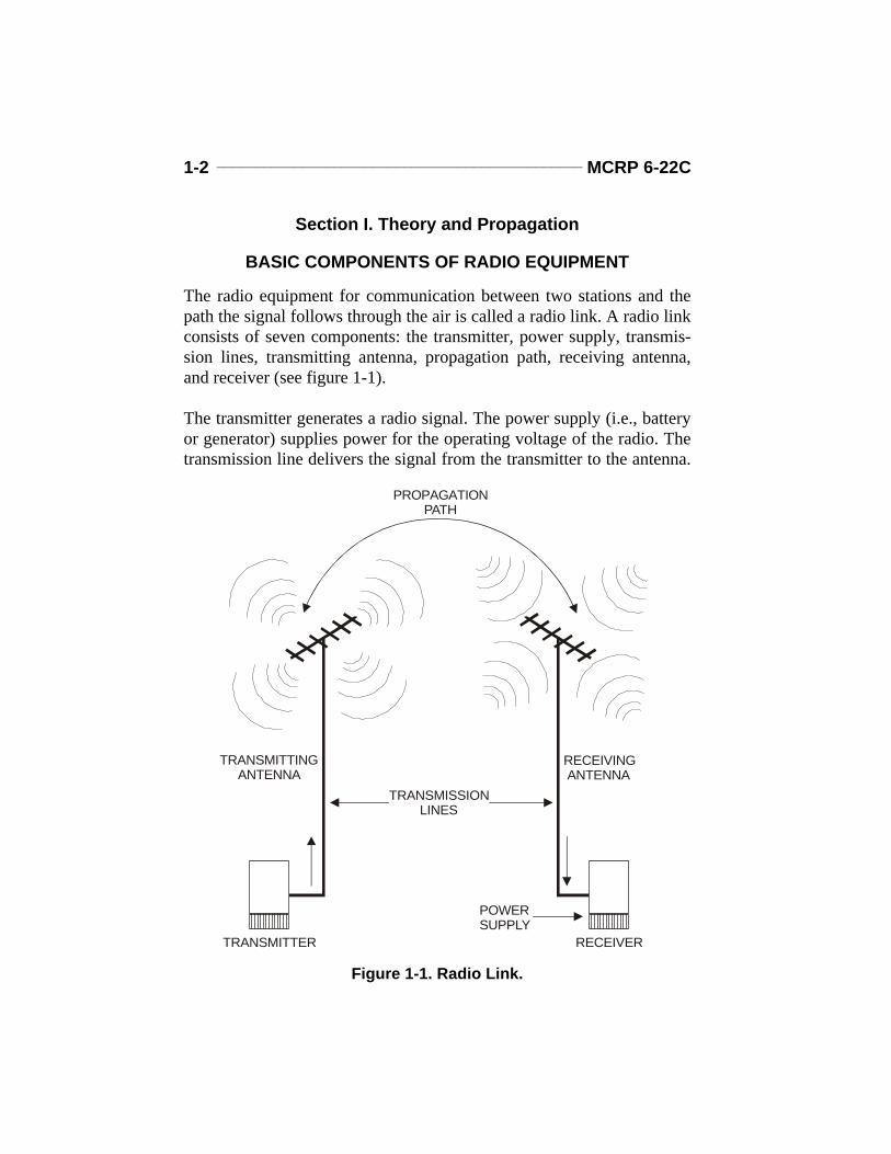
The radio equipment for communication between two stations and thepath the signal follows through the air is called a radio link. A radio linkconsists of seven components: the transmitter, power supply, transmis-sion lines, transmitting antenna, propagation path, receiving antenna,and receiver (see figure 1-1).
The transmitter generates a radio signal. The power supply (i.e., batteryor generator) supplies power for the operating voltage of the radio. Thetransmission line delivers the signal from the transmitter to the antenna.
TRANSMISSIONLINES
TRANSMITTING ANTENNA
PROPAGATIONPATH
RECEIVING ANTENNA
POWERSUPPLY
TRANSMITTER RECEIVER
Figure 1-1. Radio Link.
Radio Operator’s Handbook ______________________________ 1-3
The transmitting antenna sends the radio signal into space toward thereceiving antenna. The path in space that the radio signal follows as itgoes to the receiving antenna is the propagation path. The receivingantenna intercepts or receives the signal and sends it through a transmis-sion line to the receiver. The receiver processes the radio signal so thehuman ear can hear it.
When transmitting, the radio operator aims to provide the strongest pos-sible signal at the site of the receiving station. The best possible signal isthat signal which will provide the greatest signal-to-noise ratio at thereceiving antenna.
To transmit the best possible signal, select or determine the—
l Optimum frequency. l Best antenna for that frequency based on the available space of the
transmitting site.l Proper propagation path.
RADIO WAVES
Propagation Velocity (Speed)
Radio waves travel near the surface of the Earth and radiate skyward atvarious angles to the Earth’s surface. These electromagnetic wavestravel through space at the speed of light, approximately 300,000 kilo-meters (km) or 186,000 miles (mi) per second.
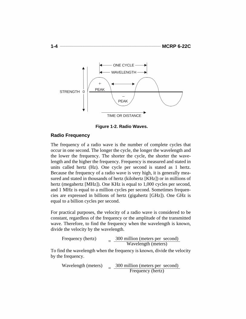
Wavelength
Wavelength is the distance between the crest of one wave and the crestof the next wave (see figure 1-2 on page 1-4). It can also be the length ofone complete cycle of the waveform. It is also the distance traveled dur-ing one complete cycle. The length of the wave is always measured inmeters.
1-4 _______________________________________________ MCRP 6-22C
Radio Frequency
The frequency of a radio wave is the number of complete cycles thatoccur in one second. The longer the cycle, the longer the wavelength andthe lower the frequency. The shorter the cycle, the shorter the wave-length and the higher the frequency. Frequency is measured and stated inunits called hertz (Hz). One cycle per second is stated as 1 hertz.Because the frequency of a radio wave is very high, it is generally mea-sured and stated in thousands of hertz (kilohertz [KHz]) or in millions ofhertz (megahertz [MHz]). One KHz is equal to 1,000 cycles per second,and 1 MHz is equal to a million cycles per second. Sometimes frequen-cies are expressed in billions of hertz (gigahertz [GHz]). One GHz isequal to a billion cycles per second.
For practical purposes, the velocity of a radio wave is considered to beconstant, regardless of the frequency or the amplitude of the transmittedwave. Therefore, to find the frequency when the wavelength is known,divide the velocity by the wavelength.
To find the wavelength when the frequency is known, divide the velocityby the frequency.
Frequency (hertz) = 300 million (meters per second)Wavelength (meters)
Wavelength (meters) = 300 million (meters per second)Frequency (hertz)
STRENGTH
TIME OR DISTANCE
ONE CYCLE
WAVELENGTH
PEAK
PEAK
0
Figure 1-2. Radio Waves.
Radio Operator’s Handbook ______________________________ 1-5
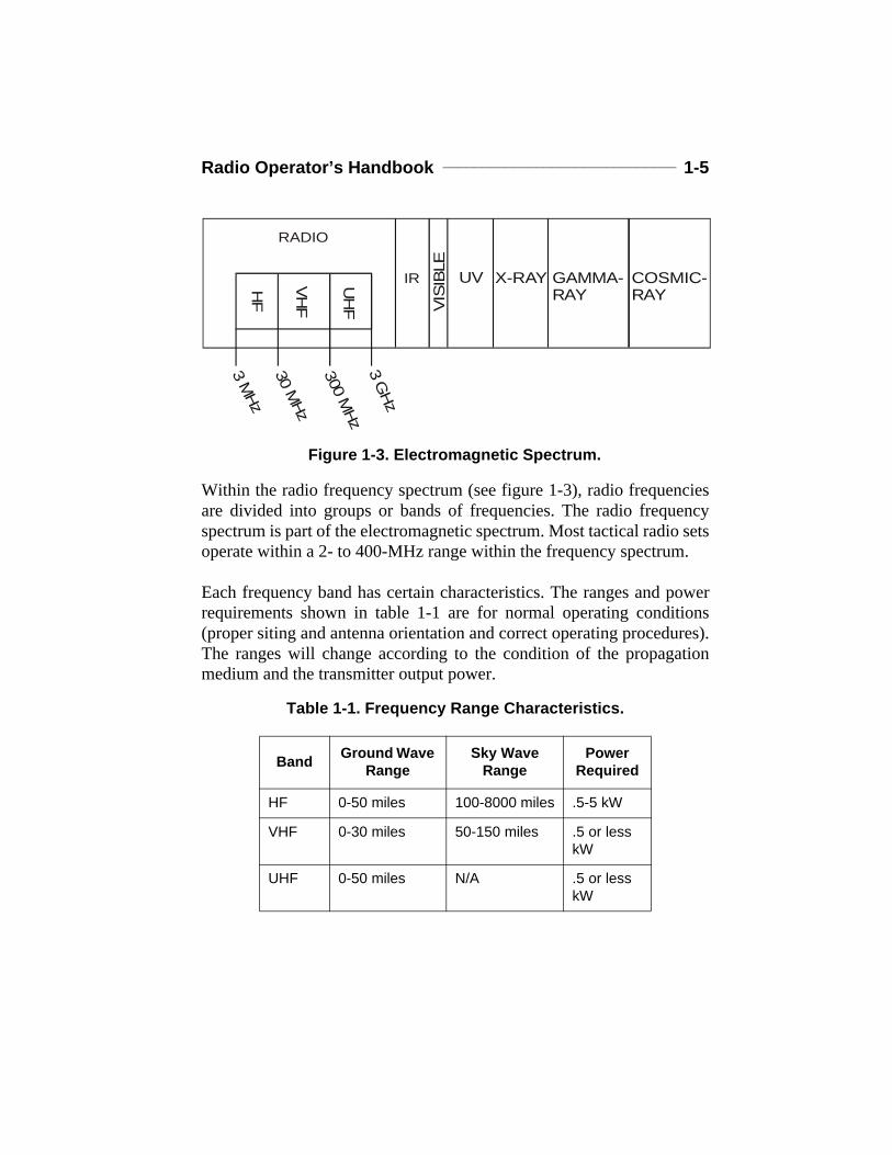
Within the radio frequency spectrum (see figure 1-3), radio frequenciesare divided into groups or bands of frequencies. The radio frequencyspectrum is part of the electromagnetic spectrum. Most tactical radio setsoperate within a 2- to 400-MHz range within the frequency spectrum.
Each frequency band has certain characteristics. The ranges and powerrequirements shown in table 1-1 are for normal operating conditions(proper siting and antenna orientation and correct operating procedures).The ranges will change according to the condition of the propagationmedium and the transmitter output power.
Table 1-1. Frequency Range Characteristics.
Band Ground Wave Range
Sky Wave Range
Power Required
HF 0-50 miles 100-8000 miles .5-5 kW
VHF 0-30 miles 50-150 miles .5 or less kW
UHF 0-50 miles N/A .5 or less kW
Figure 1-3. Electromagnetic Spectrum.VI
SIBL
E
UV X-RAY GAMMA-RAY
COSMIC-RAY
3M
Hz30
MHz
300M
Hz3
GHz
HF
VHF
UH
F
IR
RADIO
1-6 _______________________________________________ MCRP 6-22C
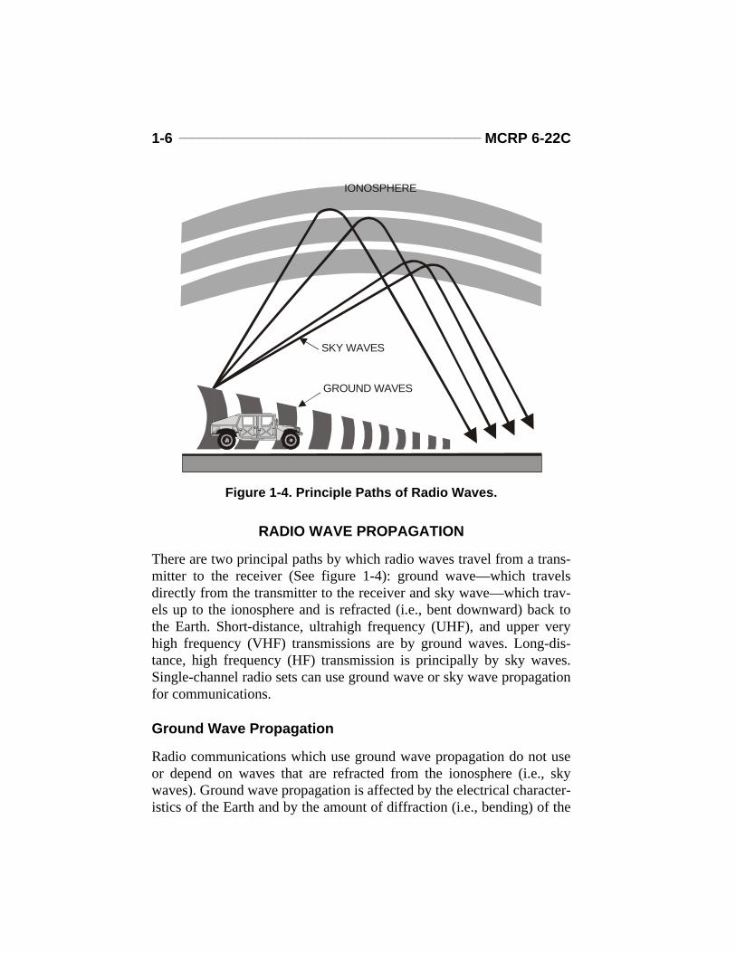
RADIO WAVE PROPAGATION
There are two principal paths by which radio waves travel from a trans-mitter to the receiver (See figure 1-4): ground wave—which travelsdirectly from the transmitter to the receiver and sky wave—which trav-els up to the ionosphere and is refracted (i.e., bent downward) back tothe Earth. Short-distance, ultrahigh frequency (UHF), and upper veryhigh frequency (VHF) transmissions are by ground waves. Long-dis-tance, high frequency (HF) transmission is principally by sky waves.Single-channel radio sets can use ground wave or sky wave propagationfor communications.
Ground Wave Propagation
Radio communications which use ground wave propagation do not useor depend on waves that are refracted from the ionosphere (i.e., skywaves). Ground wave propagation is affected by the electrical character-istics of the Earth and by the amount of diffraction (i.e., bending) of the
GROUND WAVES
IONOSPHERE
SKY WAVES
Figure 1-4. Principle Paths of Radio Waves.
Radio Operator’s Handbook ______________________________ 1-7
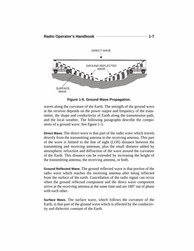
waves along the curvature of the Earth. The strength of the ground waveat the receiver depends on the power output and frequency of the trans-mitter, the shape and conductivity of Earth along the transmission path,and the local weather. The following paragraphs describe the compo-nents of a ground wave. See figure 1-5.
Direct Wave. The direct wave is that part of the radio wave which travelsdirectly from the transmitting antenna to the receiving antenna. This partof the wave is limited to the line of sight (LOS) distance between thetransmitting and receiving antennas, plus the small distance added byatmospheric refraction and diffraction of the wave around the curvatureof the Earth. This distance can be extended by increasing the height ofthe transmitting antenna, the receiving antenna, or both.
Ground Reflected Wave. The ground reflected wave is that portion of theradio wave which reaches the receiving antenna after being reflectedfrom the surface of the earth. Cancellation of the radio signal can occurwhen the ground reflected component and the direct wave componentarrive at the receiving antenna at the same time and are 180° out of phasewith each other.
Surface Wave. The surface wave, which follows the curvature of theEarth, is that part of the ground wave which is affected by the conductiv-ity and dielectric constant of the Earth.
GROUND REFLECTED
DIRECT WAVE
SURFACE WAVE
WAVE
Figure 1-5. Ground Wave Propagation.
1-8 _______________________________________________ MCRP 6-22C
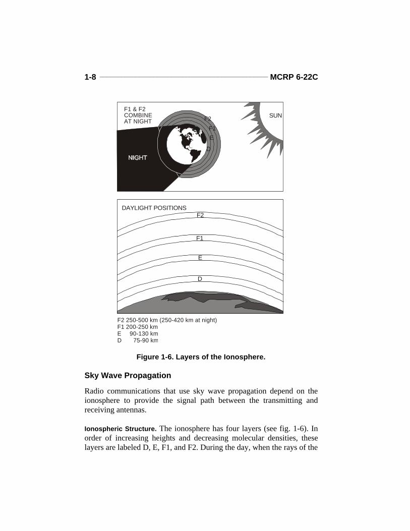
Sky Wave Propagation
Radio communications that use sky wave propagation depend on theionosphere to provide the signal path between the transmitting andreceiving antennas.
Ionospheric Structure. The ionosphere has four layers (see fig. 1-6). Inorder of increasing heights and decreasing molecular densities, theselayers are labeled D, E, F1, and F2. During the day, when the rays of the
F1 & F2
F1 E
D
F2COMBINE
F2 250-500 km (250-420 km at night)F1 200-250 kmE 90-130 kmD 75-90 km
SUNAT NIGHT
F2
F1
E
D
DAYLIGHT POSITIONS
Figure 1-6. Layers of the Ionosphere.
Radio Operator’s Handbook ______________________________ 1-9
Sun are directed toward that portion of the atmosphere, all four layersmay be present. At night, the F1 and F2 layers seem to merge into a sin-gle F layer, and the D and E layers fade out. The actual number of layers,their height above the Earth, and their relative intensity of ionization var-ies constantly. The following are layers of the ionosphere:
l D—exists only during daylight hours and has little effect in bendingthe paths of high frequency radio waves. The main effect of the Dlayer is to attenuate high frequency waves when the transmission pathis in sunlit regions.
l E—used during the day for high frequency radio transmission overintermediate distances (less than 2,400 km [1,500 mi]). At night, theintensity of the E layer decreases, and it becomes useless for radiotransmission.
l F—exists at heights up to 380 kilometers (240 mi) above the Earthand is ionized all the time. It has two well-defined layers (F1 and F2)during the day, and one layer (i.e., F) during the night. At night, the Flayer remains at a height of about 260 kilometers (170 mi) and is use-ful for long-range radio communications (over 2,400 km [1,500 mi]).The F2 layer is the most useful of all layers for long-range radio com-munications, even though its degree of ionization varies appreciablyfrom day to day.
Factors Affecting the Ionosphere. The movements of the Earth aroundthe Sun and changes in the Sun’s activity contribute to ionospheric vari-ations. There are two main classes of variations: regular, which is pre-dictable; and irregular, which occurs from abnormal behavior of the Sun.
Regular Variations of the Ionosphere. The regular variations are—
l Daily—caused by the rotation of the Earth.l Seasonal—caused by the north and south progression of the Sun.l 27-day—caused by the rotation of the Sun on its axis.l 11-year—caused by the sunspot activity cycle going from maximum
to minimum, back to maximum levels of intensity.
1-10 ______________________________________________ MCRP 6-22C
Irregular Variations of the Ionosphere. The current status of the four reg-ular variations must be anticipated when planning a communicationssystem. There are also unpredictable, irregular variations that must beconsidered. They have a degrading effect (at times blocking communica-tions) which cannot be controlled or compensated for at present. Someirregular variations are—
l Sporadic E. When it is excessively ionized, the E layer often blocksout the reflections back from the higher layers. It can also cause unex-pected propagation of signals hundreds of miles beyond the normalrange. This effect can occur at any time.
l Sudden ionospheric disturbance (SID). A sudden ionospheric distur-bance coincides with a bright solar eruption and causes abnormal ion-ization of the D layer. This effect causes total absorption of allfrequencies above approximately 1 MHz. It can occur without warn-ing during daylight hours and last from a few minutes to severalhours. When SID occurs, receivers seem to go dead.
l Ionospheric storms. During these storms, sky wave reception aboveapproximately 1.5 MHz shows low intensity and is subject to a typeof rapid blasting and fading called “flutter fading.” These storms maylast from several hours to days and usually extend over the entireEarth.
Sunspots. Sunspots generate bursts of radiation that cause high levels ofionization. The more sunspots, the greater the ionization. During periodsof low sunspot activity, frequencies above 20 MHz tend to be unusablebecause the E and F layers are too weakly ionized to reflect signals backto earth. At the peak of the sunspot cycle, however, it is not unusual tohave worldwide propagation on frequencies above 30 MHz.
Frequency Characteristics in the Ionosphere. The range of long-distanceradio transmission is determined primarily by the ionization density ofeach layer. The higher the frequency, the greater the ionization densityrequired to reflect radio waves back to Earth. The upper (i.e., E and F)layers reflect the higher frequencies because they are the most highlyionized. The D layer, which is the least ionized, does not reflect frequen-cies above approximately 500 KHz. Thus, at any given time and for each
Radio Operator’s Handbook _____________________________ 1-11
ionized layer, there is an upper frequency limit at which radio waves sentvertically upward are reflected back to Earth. This limit is called the crit-ical frequency.
Radio waves directed vertically at frequencies higher than the criticalfrequency pass through the ionized layer out into space. All radio wavesdirected vertically into the ionosphere at frequencies lower than the crit-ical frequency are reflected back to Earth. Radio waves used in commu-nications are generally directed towards the ionosphere at some obliqueangle, called the angle of incidence. Radio waves at frequencies abovethe critical frequency will be reflected back to Earth if transmitted atangles of incidence smaller than a certain angle, called the critical angle.At the critical angle and all angles larger than the critical angle the radiowaves will pass through the ionosphere if the frequency is higher thanthe critical frequency. When the angle of transmission becomes smaller,the radio waves will be reflected back to Earth.
Transmission Paths. The distance from the transmitting antenna to theplace where the sky waves first return to Earth is called the skip distance.The skip distance is dependent on the angle of incidence, the operatingfrequency, and the height and density of the ionosphere. The antennaheight, in relation to the operating frequency, affects the angle that trans-mitted radio waves strike and penetrate the ionosphere and then return toEarth. This angle of incidence can be controlled to obtain the desiredarea of coverage. Lowering the antenna will increase the angle of trans-mission and provide broad and even signal patterns in a large area. Theuse of near-vertical transmission paths is known as near-vertical inci-dence sky wave (NVIS). Raising the antenna will lower the angle ofincidence. Lowering the angle of incidence can produce a skip zone inwhich no usable signal can be received. This area is bounded by theouter edge of usable ground wave propagation and the point nearest theantenna at which the sky wave returns to Earth. In most communicationssituations, the skip zone is not a desirable condition. However, lowangles of incidence make long-distance communications possible.
When a transmitted wave is reflected back to the surface of the Earth,part of its energy is absorbed by the Earth. The remainder of its energy isreflected back into the ionosphere to be reflected back again. This means
1-12 ______________________________________________ MCRP 6-22C
of transmission—by alternately reflecting the radio wave between theionosphere and the Earth—is called hops, and it enables radio waves tobe received at great distances from the point of origin.
Maximum Usable and Lowest Usable Frequencies. There is a maximumfrequency at which a radio wave will return to Earth at a given distancewhen a given ionized layer and a transmitting antenna with a fixed angleof radiation is used. This frequency is called the maximum usable fre-quency (MUF). It is the monthly median of the daily highest frequencythat is predicted for sky wave transmission over a particular path at aparticular hour of the day. The MUF is always higher than the criticalfrequency because the angle of incidence is less than 90°. If the distancebetween the transmitter and the receiver is increased, the maximumusable frequency will also increase. Radio waves lose some of theirenergy through absorption by the D layer and the portion of the E layerof the ionosphere at certain transmission frequencies.
The total absorption is less and communications are more satisfactory ashigher frequencies are used up to the level of the MUF. The absorptionrate is greatest for frequencies ranging from approximately 500 KHz to 2MHz during the day. At night, the absorption rate decreases for all fre-quencies. As the frequency of transmission over any sky wave path isdecreased from high to low frequencies, a frequency will be reached atwhich the received signal just overrides the level of atmospheric andother radio noise interference. This is called the lowest useful frequency(LUF) because frequencies lower than the LUF are too weak for usefulcommunications. The LUF also depends on the power output of thetransmitter as well as the transmission distance. When the LUF is greaterthan the MUF, no sky wave transmission is possible.
Radio Operator’s Handbook _____________________________ 1-13
Section II. Modulation and Single Side Band Transmission
Radio communications equipment is used primarily to transmit voiceand data. Although sound can be converted to audio frequency electricalenergy, it is not practical to transmit it in this energy form through theEarth’s atmosphere by electromagnetic radiation. For example, efficienttransmission of a 20-hertz audio signal would require an antenna almost8,000 kilometers (5,000 mi) long. This would not apply when radio fre-quency electrical energy is used to carry the intelligence. When radiofrequency electrical energy is used, great distances can be covered; effi-cient antennas for radio frequencies are of practical lengths; and antennapower losses are at reasonable levels.
The frequency of the radio wave affects its propagation characteristics.In the low frequency band (.03 to.3 MHz), the ground wave is very use-ful for communications over great distances. The ground wave signalsare quite stable and show little seasonal variation. In the medium fre-quency band (.3 to 3.0 MHz), the range of the ground wave varies fromabout 24 kilometers (15 mi) at 3 MHz, to about 640 kilometers (400 mi)at the lowest frequencies of this band. Sky wave reception is possibleduring the day or night at any of the lower frequencies in this band. Atnight, the sky wave is receivable at distances up to 12,870 kilometers(8,000 mi). In the high frequency band (3 to 30 MHz), the range of theground wave decreases as frequency increases, and the sky waves aregreatly influenced by ionospheric considerations.
In the very high frequency band (30 to 300 MHz), there is no usableground wave and only slight refraction of sky waves by the ionosphereat the lower frequencies. The direct wave provides communications ifthe transmitting and receiving antennas are elevated high enough abovethe surface of the Earth.
In the ultrahigh frequency band (300 to 3,000 MHz), the direct wavemust be used for all transmissions. Communications are limited to ashort distance beyond the horizon. Lack of static and fading in thesebands makes line of sight reception very satisfactory. Antennas that arehighly directional can be used to concentrate the beam of radio fre-quency (RF) energy, thus, increasing the signal intensity.
1-14 ______________________________________________ MCRP 6-22C
MODULATION
Both amplitude modulation (AM) and frequency modulation (FM) trans-mitters produce RF carriers. The carrier is a wave of constant amplitude,frequency, and phase which can be modulated by changing its ampli-tude, frequency, or phase. Thus, the RF carrier “carries” intelligence bybeing modulated. Modulation is the process of superimposing intelli-gence (voice or coded signals) on the carrier.
Amplitude Modulation
Amplitude modulation is the variation of the RF power output of a trans-mitter at an audio rate. In other words, the RF energy increases anddecreases in power according to the audio frequencies superimposed onthe carrier signal.
When audio frequency signals are superimposed on the radio frequencycarrier signal, additional RF signals are generated. These additional fre-quencies are equal to the sum of, and the difference between the audiofrequencies and the radio frequency used. For example, assume a 500-KHz carrier is modulated by a 1-KHz audio tone. Two new frequenciesare developed, one at 501 KHz (the sum of 500 KHz and 1 KHz) and theother at 499 KHz (the difference between 500 KHz and 1 KHz). If acomplex audio signal is used instead of a single tone, two new frequen-cies will be set up for each of the audio frequencies involved. The newfrequencies resulting from superimposing an audio frequency (AF) sig-nal on an RF signal are called side bands.
When the RF carrier is modulated by complex tones such as speech,each separate frequency component of the modulating signal producesits own upper and lower side band frequencies. The side band that con-tains the sum of the RF and AF signals is called the upper side band. Theside band that contains the difference between the RF and AF signals iscalled the lower side band.
The space occupied by a carrier and its associated side bands inthe radio frequency spectrum is called a channel. In amplitude modula-tion, the width of the channel (bandwidth) is equal to twice the highest
Radio Operator’s Handbook _____________________________ 1-15
modulating frequency. For example, if a 5,000 KHz (5 MHz) carrier ismodulated by a band of frequencies ranging from 200 to 5,000 cycles (.2to 5 KHz), the upper side band extends from 5,000.2 to 5,005 KHz. Thelower side band extends from 4,999.8 KHz to 4,995 KHz. Thus, thebandwidth is the difference between 5,005 KHz and 4,995 KHz, a totalof 10 KHz.
Frequency Modulation
Frequency modulation is the process of varying the frequency (ratherthan the amplitude) of the carrier signal in accordance with the varia-tions of the modulating signals. The amplitude or power of the FM car-rier does not vary during modulation.
The frequency of the carrier signal when it is not modulated is called thecenter or rest frequency. When a modulating signal is applied to thecarrier, the carrier signal will move up and down in frequency, awayfrom the center or rest frequency.
The amplitude of the modulating signal determines how far away fromthe center frequency the carrier will move. This movement of the carrieris called deviation; how far the carrier moves is called the amount ofdeviation. During reception of the FM signal, the amount of deviationdetermines the loudness or volume of the signal.
The FM signal leaving the transmitting antenna is constant in amplitudebut varies in frequency according to the audio signal. As the signal trav-els to the receiving antenna, it picks up natural and man-made electricalnoises that cause amplitude variations in the signal. All of these undesir-able amplitude variations are amplified as the signal passes through suc-cessive stages of the receiver until the signal reaches a part of thereceiver called the limiter. The limiter is unique to FM receivers as is thediscriminator.
The limiter eliminates the amplitude variations in the signal, then passesit on to the discriminator which is sensitive to variations in the frequencyof the RF wave. The resultant constant amplitude, frequency-modulatedsignal is then processed by the discriminator circuit which changes the

1-16 ______________________________________________ MCRP 6-22C
frequency variations into corresponding voltage amplitude variations.These voltage variations reproduce the original modulating signal in aheadset, loudspeaker, or teletypewriter. Frequency modulation is gener-ally used by radiotelephone transmitters operating in the VHF andhigher frequency bands.
SINGLE SIDE BAND TRANSMISSION
The intelligence of an AM signal is contained solely in the side bands.Each side band contains all the intelligence needed for communications.Therefore, one side band and the carrier signal can be eliminated. This isthe principle on which single side band (SSB) communications is based.Although both side bands are generated within the modulation circuitryof the SSB radio set, the carrier and one side band are removed beforeany signal is transmitted.
The side band that is higher in frequency than the carrier is called theupper side band (USB). The side band that is lower in frequency than thecarrier is called the lower side band (LSB). Either side band can be usedfor communications as long as both the transmitter and the receiver areadjusted to the same side band. Most SSB equipment operates in theUSB mode. The transmission of only one side band leaves open that por-tion of the RF spectrum normally occupied by the other side band of anAM signal. This allows more emitters to be used within a given fre-quency range.
Single side band transmission is used in applications when it is desiredto—
l Obtain greater reliability. l Limit size and weight of equipment. l Increase effective output without increasing antenna voltage. l Operate a large number of radio sets without heterodyne interference
(e.g., whistles and squeals) from radio frequency carriers. l Operate over long ranges without loss of intelligibility because of
selective fading.
Chapter 2
Single-Channel Radio
SINGLE-CHANNEL RADIO COMMUNICATIONS EQUIPMENT
Single-channel radio is the principal means of communications supportfor MAGTF maneuver units. SCR communications equipment is easy tooperate. The networks are easily established, rapidly reconfigured, and,most importantly, easily maintained on the move. SCR provides securevoice communications and supports limited data information exchange.SCR in the VHF and UHF bands is normally limited to line of sight. Inthe HF band, SCR can support long-range communications. SCR satel-lite communications (SATCOM) provides mobility, flexibility, and easeof operation with unlimited range. Limitations of SCR include suscepti-bility to enemy electronic warfare (i.e., cosite, terrain, and atmosphericinterference); the requirement for close coordination and detailed plan-ning (i.e., a need for common timing, frequency, and equipment); andlimited spectrum availability. The latter is particularly critical in the caseof SATCOM.
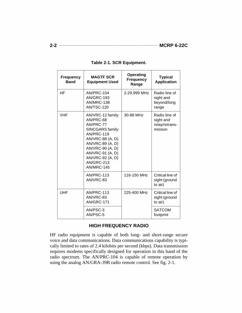
MAGTF SCR equipment is fielded in many configurations and includeshand-held, manpack, vehicle-mounted, bench-mounted, and shelteredradios. These radios operate in simplex and half-duplex modes. Themost widely employed tactical radios provide integrated communica-tions security (COMSEC) and jam resistance through frequency hop-ping. Tactical SCRs operate in the three military radio frequency bandsshown in Table 2-1 on page 1-2.
2-2 _______________________________________________ MCRP 6-22C
HIGH FREQUENCY RADIO
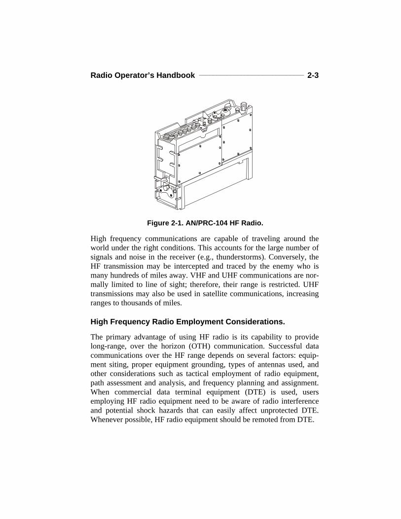
HF radio equipment is capable of both long- and short-range securevoice and data communications. Data communications capability is typi-cally limited to rates of 2.4 kilobits per second (kbps). Data transmissionrequires modems specifically designed for operation in this band of theradio spectrum. The AN/PRC-104 is capable of remote operation byusing the analog AN/GRA-39B radio remote control. See fig. 2-1.
Table 2-1. SCR Equipment.
Frequency Band
MAGTF SCREquipment Used
Operating Frequency
Range
Typical Application
HF AN/PRC-104AN/GRC-193AN/MRC-138AN/TSC-120
2-29.999 MHz Radio line of sight and beyond/long range
VHF AN/VRC-12 family:AN/PRC-68AN/PRC-77SINCGARS family:AN/PRC-119AN/VRC-88 (A, D)AN/VRC-89 (A, D)AN/VRC-90 (A, D)AN/VRC-91 (A, D)AN/VRC-92 (A, D)AN/GRC-213AN/MRC-145
30-88 MHz Radio line of sight and relay/retrans-mission
AN/PRC-113AN/VRC-83
116-150 MHz Critical line of sight (ground to air)
UHF AN/PRC-113AN/VRC-83AN/GRC-171
225-400 MHz Critical line of sight (ground to air)
AN/PSC-3AN/PSC-5
SATCOM footprint
Radio Operator’s Handbook ______________________________ 2-3
High frequency communications are capable of traveling around theworld under the right conditions. This accounts for the large number ofsignals and noise in the receiver (e.g., thunderstorms). Conversely, theHF transmission may be intercepted and traced by the enemy who ismany hundreds of miles away. VHF and UHF communications are nor-mally limited to line of sight; therefore, their range is restricted. UHFtransmissions may also be used in satellite communications, increasingranges to thousands of miles.
High Frequency Radio Employment Considerations.
The primary advantage of using HF radio is its capability to providelong-range, over the horizon (OTH) communication. Successful datacommunications over the HF range depends on several factors: equip-ment siting, proper equipment grounding, types of antennas used, andother considerations such as tactical employment of radio equipment,path assessment and analysis, and frequency planning and assignment.When commercial data terminal equipment (DTE) is used, usersemploying HF radio equipment need to be aware of radio interferenceand potential shock hazards that can easily affect unprotected DTE.Whenever possible, HF radio equipment should be remoted from DTE.
Figure 2-1. AN/PRC-104 HF Radio.
2-4 _______________________________________________ MCRP 6-22C
High Frequency Radio Environmental Limitations
The primary limiting factors when using HF radios are frequency alloca-tion and management and bandwidth availability. Frequency allocationand management is concerned with frequency, time of day, time of year,and location. The ability to reflect HF radio waves off the ionosphere toa distant location is in a constant state of flux because of activity in theionosphere. The Sun’s radiation causes disturbances in the ionosphere,with most changes taking place in what is known as the F layer (seechapter 1 for more details). Sunrise and sunset can be the most difficulttimes for HF communications. The F layer splits into two separate layersaround sunrise and recombines into one layer around sunset. These splitsaffect transmission distances as the area “skipped over” increases anddecreases. At times, solar storms can eliminate all HF communications.HF transmission paths must be constantly monitored to achieve adependable HF link. HF radio data communications capabilities are lim-ited by the bandwidth that is imposed by legal constraints and the phys-ics of the spectrum. The bandwidth available in the HF spectrum limitsthe channel bandwidth, which limits data throughput.
High Frequency Propagation
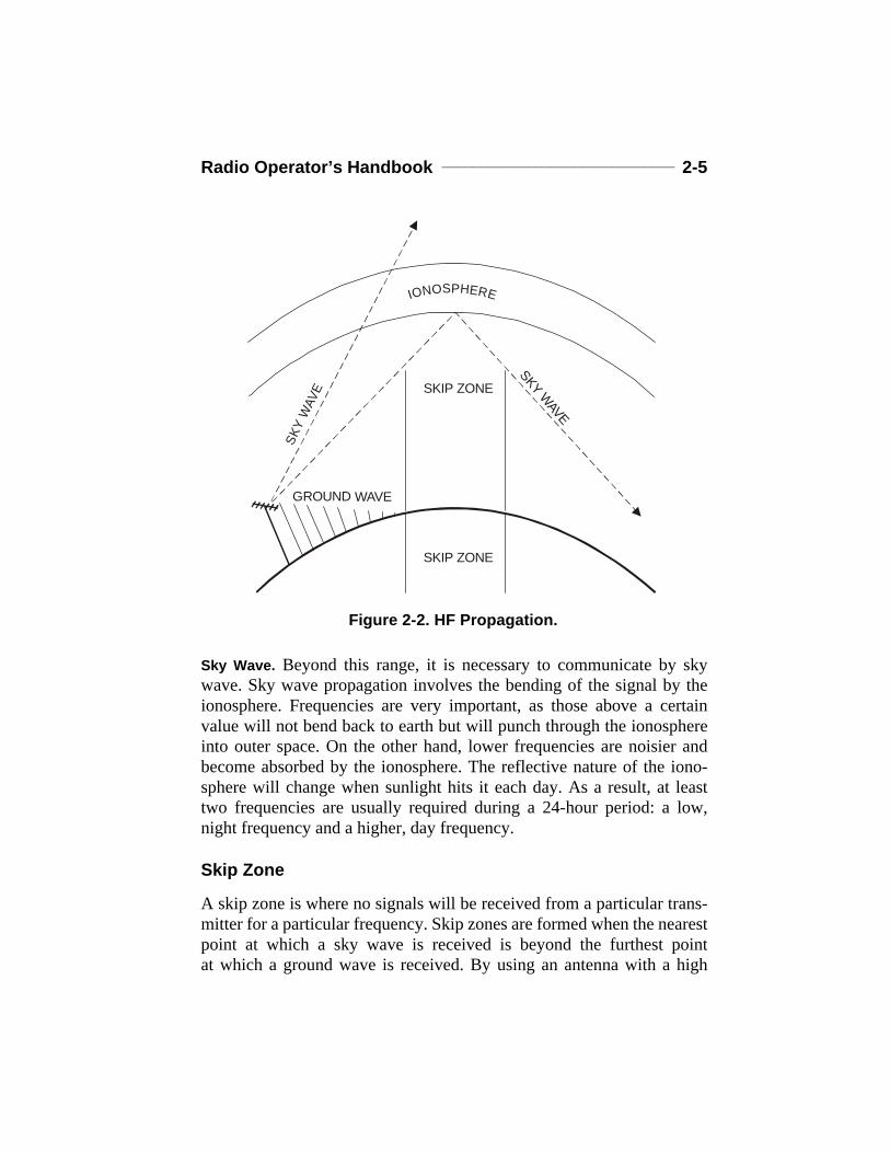
There are two modes of propagation in HF: ground wave and sky wave.See figure 2-2.
Ground Wave. Ground wave propagation involves the transmission of asignal along the surface of the ground. The maximum ground waverange for most tactical HF communications is about 20 to 30 kilometers(12 to 22 miles) for manpack equipment and 80 to 100 kilometers forhigh-power vehicular and van equipment. The range may be decreasedby heavy vegetation (e.g., Camp Lejeune), mountainous terrain (e.g.,Camp Pendleton), or dry desert soil (e.g., Twenty-nine Palms). A groundwave circuit will generally be free of fading and may last for the entire24-hour period without the need to change frequencies.
Radio Operator’s Handbook ______________________________ 2-5
Sky Wave. Beyond this range, it is necessary to communicate by skywave. Sky wave propagation involves the bending of the signal by theionosphere. Frequencies are very important, as those above a certainvalue will not bend back to earth but will punch through the ionosphereinto outer space. On the other hand, lower frequencies are noisier andbecome absorbed by the ionosphere. The reflective nature of the iono-sphere will change when sunlight hits it each day. As a result, at leasttwo frequencies are usually required during a 24-hour period: a low,night frequency and a higher, day frequency.
Skip Zone
A skip zone is where no signals will be received from a particular trans-mitter for a particular frequency. Skip zones are formed when the nearestpoint at which a sky wave is received is beyond the furthest pointat which a ground wave is received. By using an antenna with a high
Figure 2-2. HF Propagation.
GROUND WAVE
SKIP ZONE
SKIP ZONE
SKY WAVE
SKY
WAV
E
IONOSPHERE
2-6 _______________________________________________ MCRP 6-22C
radiation take-off angle (i.e., the angle measured from the Earth’s sur-face to horizon up to the direction of propagation towards the iono-sphere), HF radio waves can be bounced off the ionosphere and comeback to earth closer than they can with more commonly used antennas.This can cause the skip zone to disappear if the waves do not punchthrough.
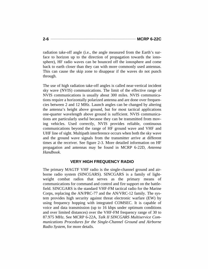
The use of high radiation take-off angles is called near-vertical incidentsky wave (NVIS) communications. The limit of the effective range ofNVIS communications is usually about 300 miles. NVIS communica-tions require a horizontally polarized antenna and are done over frequen-cies between 2 and 12 MHz. Launch angles can be changed by alteringthe antenna’s height above ground, but for most tactical applicationsone-quarter wavelength above ground is sufficient. NVIS communica-tions are particularly useful because they can be transmitted from mov-ing vehicles. Used correctly, NVIS provides reliable, continuouscommunications beyond the range of HF ground wave and VHF andUHF line of sight. Multipath interference occurs when both the sky waveand the ground wave signals from the transmitter arrive at differenttimes at the receiver. See figure 2-3. More detailed information on HFpropagation and antennas may be found in MCRP 6-22D, AntennaHandbook.
VERY HIGH FREQUENCY RADIO
The primary MAGTF VHF radio is the single-channel ground and air-borne radio system (SINCGARS). SINCGARS is a family of light-weight combat radios that serves as the primary means ofcommunications for command and control and fire support on the battle-field. SINCGARS is the standard VHF-FM tactical radio for the MarineCorps, replacing the AN/PRC-77 and the AN/VRC-12 family. The sys-tem provides high security against threat electronic warfare (EW) byusing frequency hopping with integrated COMSEC. It is capable ofvoice and data transmission (up to 16 kbps under optimum conditionsand over limited distances) over the VHF-FM frequency range of 30 to87.975 MHz. See MCRP 6-22A, Talk II SINCGARS Multiservice Com-munications Procedures for the Single-Channel Ground and AirborneRadio System, for more details.
Radio Operator’s Handbook ______________________________ 2-7
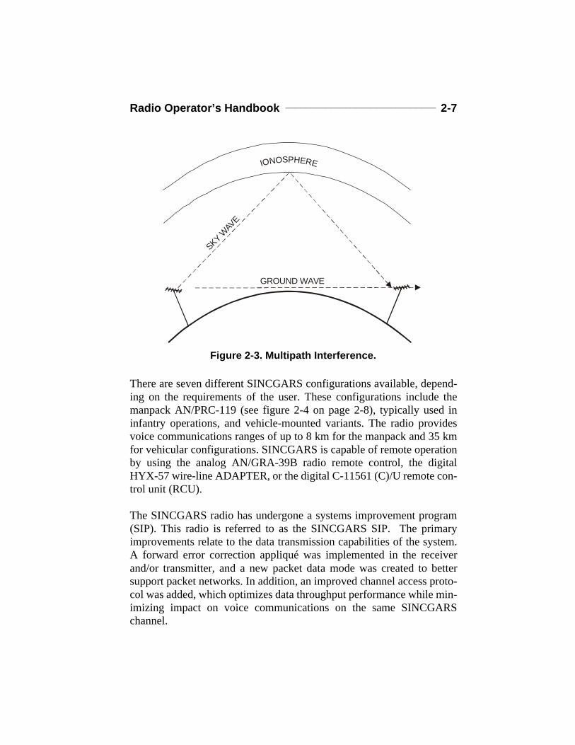
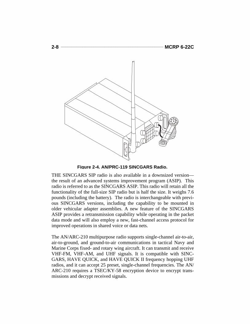
There are seven different SINCGARS configurations available, depend-ing on the requirements of the user. These configurations include themanpack AN/PRC-119 (see figure 2-4 on page 2-8), typically used ininfantry operations, and vehicle-mounted variants. The radio providesvoice communications ranges of up to 8 km for the manpack and 35 kmfor vehicular configurations. SINCGARS is capable of remote operationby using the analog AN/GRA-39B radio remote control, the digitalHYX-57 wire-line ADAPTER, or the digital C-11561 (C)/U remote con-trol unit (RCU).
The SINCGARS radio has undergone a systems improvement program(SIP). This radio is referred to as the SINCGARS SIP. The primaryimprovements relate to the data transmission capabilities of the system.A forward error correction appliqué was implemented in the receiverand/or transmitter, and a new packet data mode was created to bettersupport packet networks. In addition, an improved channel access proto-col was added, which optimizes data throughput performance while min-imizing impact on voice communications on the same SINCGARSchannel.
Figure 2-3. Multipath Interference.
GROUND WAVE
SKY WAV
E
IONOSPHERE
2-8 _______________________________________________ MCRP 6-22C
THE SINCGARS SIP radio is also available in a downsized version—the result of an advanced systems improvement program (ASIP). Thisradio is referred to as the SINCGARS ASIP. This radio will retain all thefunctionality of the full-size SIP radio but is half the size. It weighs 7.6pounds (including the battery). The radio is interchangeable with previ-ous SINCGARS versions, including the capability to be mounted inolder vehicular adapter assemblies. A new feature of the SINCGARSASIP provides a retransmission capability while operating in the packetdata mode and will also employ a new, fast-channel access protocol forimproved operations in shared voice or data nets.
The AN/ARC-210 multipurpose radio supports single-channel air-to-air,air-to-ground, and ground-to-air communications in tactical Navy andMarine Corps fixed- and rotary wing aircraft. It can transmit and receiveVHF-FM, VHF-AM, and UHF signals. It is compatible with SINC-GARS, HAVE QUICK, and HAVE QUICK II frequency hopping UHFradios, and it can accept 25 preset, single-channel frequencies. The AN/ARC-210 requires a TSEC/KY-58 encryption device to encrypt trans-missions and decrypt received signals.
Figure 2-4. AN/PRC-119 SINCGARS Radio.
Radio Operator’s Handbook ______________________________ 2-9
Hand-Held Very High Frequency Radios
Radio operators may have the opportunity to use various commercialoff-the-shelf (COTS) VHF radios in the Fleet Marine Force (FMF). Allof these radios have been open-purchased by the user units and are notpart of the official Marine Corps table of equipment. Therefore, theyhave not been assigned a table of authorization material control number(TAMCN).
These hand-held radios are typically small, lightweight, battery-poweredequipment which provides clear (and in some cases secure) voice com-munications on up to 100 different channels. Some models come withheadsets and microphones. Hand-held radios are mostly used at theinfantry-squad level or in maritime prepositioning force (MPF) offloads.
Very High Frequency Radio Employment Considerations
Operator maintenance of the radio equipment, antennas, cable assem-blies, and equipment grounding as well as proper planning and selectionare essential to reliable communications. Frequency separation, radioantenna separation, remote rekeying when using COMSEC, and poweroutput are significant employment factors. SINCGARS may be limitedto the single-channel mode when operating with some Navy ships. WhenSINCGARS is employed in the frequency hopping mode, the followingoperating factors need to be taken into account: hopset (i.e., frequencysegment allocation), net sych time and mission date, antenna placement(cosite interference is more of a concern than in the single-channel oper-ating mode), and power setting. SINCGARS radios configured for dif-ferent hopsets that dial into the same numbered net will not be able tocommunicate. MCRP 6-22A provides detailed information on theemployment of SINCGARS.
VHF SCR is the primary communications system for combat and com-bat support units while on the move. The predominant mode of operationis secure voice. However, use of VHF radio for data communicationswill increase with the fielding of tactical information systems at the bat-talion level and below. Small, hand-held VHF radios are used at thesmall-unit level in the MAGTF. These radios are often commercial items
2-10 ______________________________________________ MCRP 6-22C
that lack compatibility with SINCGARS and do not have integratedCOMSEC. Their use should be governed accordingly.
Very High Frequency Radio Environmental Limitations
The primary limiting factors when using VHF radios are range and fre-quency availability. VHF radios can provide reliable communicationsfor ranges of up to 10 miles, depending on the equipment operating con-straints and the operating environment. Unit location must be consideredwhen employing radios that operate in the VHF spectrum. Most circuitsare limited to radio line of sight, known as four-thirds earth curvature.VHF radio signals essentially follow the curvature of the earth to a dis-tance that is approximately one-third greater than the distance to thehorizon. Foliage interferes with VHF signals and may reduce normaloperating ranges to significantly less than 10 miles.
Very High Frequency Propagation
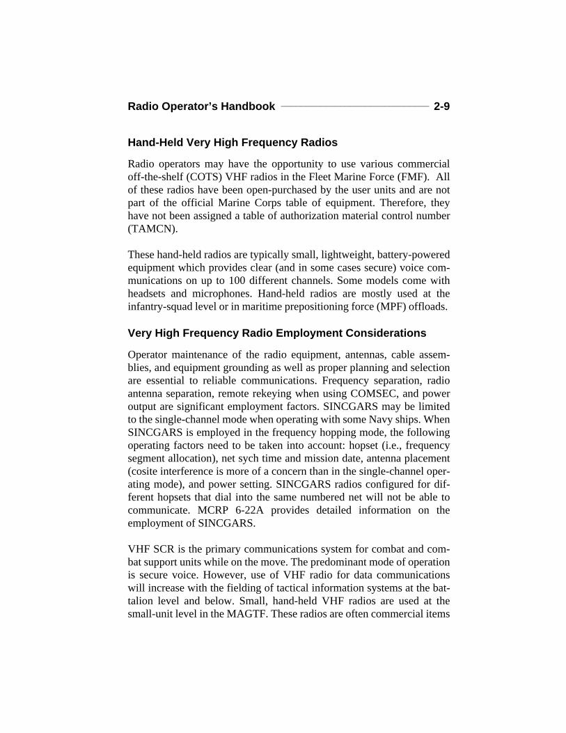
Radios in the SINCGARS family are the principal VHF transceiversused by the Marine Corps. The mode of communications used in thisrange is frequently referred to as frequency modulation. VHF willextend slightly beyond line of sight due to diffraction or bending of thesignal by the atmosphere (see fig. 2-5). At frequencies in the 30-MHzrange, VHF will often act like HF ground wave. The range of reliablecommunications is generally no more than 15 to 20 kilometers (9.3 to12.4 mi) under normal field conditions for manpack equipment. Vehicle-mounted equipment may communicate farther because of higher trans-mitter power and better antennas.
Figure 2-5. VHF Diffraction.
RECEIVING ANTENNA
DIFFRACTION
ANGLE
DIFFRACTED WAVEEARTH
TRANSMITTING ANTENNA
Radio Operator’s Handbook _____________________________ 2-11
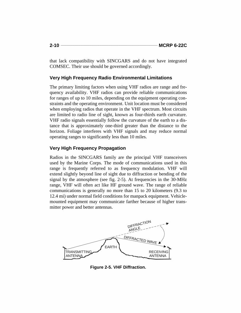
VHF LOS can also be plagued by multipath interference when the directray and a reflected ray traveling over a slightly longer path combine atthe receiver antenna so that they periodically cancel or reinforce eachother (see fig. 2-6). The signal fades in and out over a period of time as aresult. Fading is not as great a problem with immobile equipmentbecause corrective action can be taken, but fading can cause significantproblems when one or more of the units are mobile.
ULTRAHIGH FREQUENCY RADIO
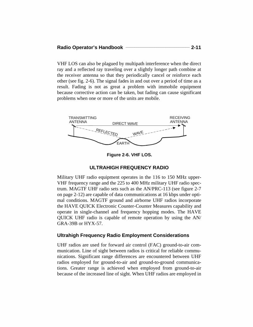
Military UHF radio equipment operates in the 116 to 150 MHz upper-VHF frequency range and the 225 to 400 MHz military UHF radio spec-trum. MAGTF UHF radio sets such as the AN/PRC-113 (see figure 2-7on page 2-12) are capable of data communications at 16 kbps under opti-mal conditions. MAGTF ground and airborne UHF radios incorporatethe HAVE QUICK Electronic Counter-Counter Measures capability andoperate in single-channel and frequency hopping modes. The HAVEQUICK UHF radio is capable of remote operation by using the AN/GRA-39B or HYX-57.
Ultrahigh Frequency Radio Employment Considerations
UHF radios are used for forward air control (FAC) ground-to-air com-munication. Line of sight between radios is critical for reliable commu-nications. Significant range differences are encountered between UHFradios employed for ground-to-air and ground-to-ground communica-tions. Greater range is achieved when employed from ground-to-airbecause of the increased line of sight. When UHF radios are employed in
RECEIVING ANTENNADIRECT WAVE
WAVEREFLECTED
EARTH
TRANSMITTING ANTENNA
Figure 2-6. VHF LOS.
2-12 ______________________________________________ MCRP 6-22C
the frequency hopping mode, the following operating factors must beunderstood for proper operation: hopset, time of day, antenna placement,and power setting.
Ultrahigh Frequency Radio Environmental Limitations
The primary limiting factor when using UHF radios is range (i.e., criticalline of sight). Critical line of sight can be described as “what you see iswhat you get.” As long as the radio’s antenna has optical line of sight toanother radio’s antenna, the two will be able to transmit and receive. Forthis reason, UHF radios are used primarily in air-to-ground communica-tions.
Figure 2-7. AN/PRC-113. UHF Radio.
Radio Operator’s Handbook _____________________________ 2-13
Ultrahigh Frequency-Tactical Satellite
The AN/PSC-5 is a portable, battery-operated, half-duplex UHF trans-ceiver. It is employed for long-range communications. It weighs approx-imately 14 pounds including antenna and batteries. The AN/PSC-5provides two-way voice and data communications by satellite. It oper-ates on the UHF frequency band of 225- to 400-MHz range. It provides2,400 to 16,000-bits per second (bps) data rate, depending on mode set-ting. Only one operator is required to operate it. The United StatesMarine Corps UHF tactical SATCOM system supports and augmentsthe high precedence command and control and common-user, single-channel requirements of a Marine air-ground task force and its majorsubordinate headquarters.
The space segments used by the AN/PSC-5 are the Fleet Satellite Com-munications, leased satellite communications, and UHF follow-on satel-lites. All the satellites are located in geosynchronous orbits and permitinterconnections among mobile, ground terminals. The one-way distanceto servicing satellites is approximately 25,000 miles, resulting in around-trip propagation delay of approximately one-quarter of a second.The shape of the satellite footprints is roughly circular but elongatedfrom north to south. This is caused by the angle at which the signal hitsthe Earth’s surface and by the curvature of the Earth’s surface.
Multiple-access schemes can operate either with fixed-channel assign-ments to the various users or with channels being assigned in varyingfashion according to demand. The latter is called demand assigned mul-tiple access (DAMA). With demand assignment, the user makes a chan-nel request, and a channel is allocated after a brief time lag. The DAMAscheme of operation is employed on UHF-tactical satellite (TACSAT) toshare available channels more efficiently. The radio systems are compat-ible with the KY-57 (wideband mode only), the KY-99 and ANDVT(narrowband mode only), and the KG-84C (wideband or narrowband)COMSEC equipment. This radio equipment is also capable of remoteoperations by using the AN/GRA-39B (narrowband mode) or HYX-57(wide-band mode).

2-14 ______________________________________________ MCRP 6-22C
TACSAT Radio Employment Considerations. Because of TACSAT’s lim-ited availability, the MAGTF employs TACSAT primarily to supportcritical, long-range communications requirements (e.g., communicationssupport for deep reconnaissance operations or connectivity to the tacticalechelon of a MEU[SOC] when deployed ashore). The AN/PSC-5 is theprimary DAMA-capable, TACSAT radio available to the MAGTF (seefig. 2-8). TACSAT limitations include the competition for available fre-quency resources and channel time on the satellite. If only narrow bandchannels are available, channel-data rates are limited to 2,400 bps. Chan-nel congestion, noise, and network saturation will affect the informationflow on satellite channels and will require a significant reduction in thedata transmission rates to sustain data communications. Transmit powerselection can be critical. Increasing the transmit power can decrease neteffectiveness. Larger directional antennas provide increased signal gain,which increases the transmitted signal power. Antennas for these sys-tems are lightweight and fragile and, therefore, require constant mainte-nance and inspection for proper operation. Satellites are sharedresources. Exact frequency, bandwidth, and power of every carrier trans-mitted through the satellite is strictly controlled by a higher authority.
TACSAT Radio Environmental Limitations. The primary environmentallimitations on TACSAT radios are signal propagation delay, location onthe Earth, terrain masking, and weather effects. Timing between DTEcan be a critical factor in SATCOM because the satellite, actingas a relay between radios, is about 25,000 miles away. There is
Figure 2-8. AN/PSC-5 UHF TACSAT Radio.
Radio Operator’s Handbook _____________________________ 2-15
approximately a one-fourth second propagation delay between sendingand receiving stations. This delay can interfere with systems that auto-matically retransmit if an acknowledgment is not received after a veryshort time-out period. As unit location changes, the “look angle” (i.e.,angle above the horizon) to the satellite can affect net reliability. Theorbit of a satellite allows it to cover a certain footprint on the earth. Sat-ellites in equatorial orbit can cover large portions of the Earth, both northand south of the equator, but as the user moves closer to the Earth’spoles, the TACSAT terminal may exceed the satellite footprint. This willcause intermittent or lost communications. Terrain can also have thiseffect by interfering with the satellite and TACSAT terminal line ofsight. Thunderstorms, heavy snowstorms, and hail also affect satellitetransmissions by damaging antennas and changing the electromagneticenvironment.
Ultrahigh Frequency Propagation
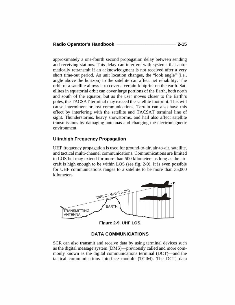
UHF frequency propagation is used for ground-to-air, air-to-air, satellite,and tactical multi-channel communications. Communications are limitedto LOS but may extend for more than 500 kilometers as long as the air-craft is high enough to be within LOS (see fig. 2-9). It is even possiblefor UHF communications ranges to a satellite to be more than 35,000kilometers.
DATA COMMUNICATIONS
SCR can also transmit and receive data by using terminal devices suchas the digital message system (DMS)—previously called and more com-monly known as the digital communications terminal (DCT)—and thetactical communications interface module (TCIM). The DCT, data
Figure 2-9. UHF LOS.
DIRECT WAVE (LOS)
EARTHTRANSMITTING ANTENNA
2-16 ______________________________________________ MCRP 6-22C
automated communications terminal (DACT), and the TCIM are criticalin enabling data communications at the tactical level over SCRs.
Digital Message System-AN/PSC-2
The DMS-AN/PSC-2 is a hand-held communications device that can beoperated with either a standard military radio or telephone field wireequipment. The DMS is used to compose, edit, display, transmit, andreceive information. By menu selection, formatted text, free text, anddigitized map messages are transmitted over tactical communicationsequipment. DMS is being used directly for air support, fire supportcoordination, reconnaissance, medical evacuation, and other functions.DMS uses a burst transmission capability which reduces the vulnerabil-ity to enemy radio direction finding and jamming.
Data Automated Communications Terminal
The DACT is a small, tactical computer and communications terminalwhich gives users the capability to receive, process, and transmit variousmessages, to include text and symbology, used by tactical data systems.The DACT will effectively replace the DCT when it achieves full opera-tional capability in FY 03, and it will provide much greater functionalitybelow battalion levels. This will include an embedded global positioningsystem (GPS) receiver, the ability to share a common picture of the bat-tlespace, automated data exchange, and MAGTF command, control,communications, computers, and intelligence (C4I) network connectiv-ity. The DACT will be transportable by foot-mobile Marines andmounted in tactical or armored vehicles.
Tactical Communications Interface Module
The TCIM provides the communications link between the tactical com-puters of the communications and information systems within theMAGTF and the local and wide area networks, switched backbone(SBB), and radio nets. There are two versions of the TCIM card: aninternal personal computer asynchronous transfer card to mount directlyin the computer, and an external version with the card mounted in a por-table chassis. TCIM software was developed for open-systems architec-tures. Small computer systems interfaces (SCSI) provide interoperabilitybetween the TCIM and other Marine Corps computers.
Chapter 3
Equipment Siting and Grounding Techniques
Two factors play an important role in equipment siting: optimum com-munications and camouflage. It is often difficult to find communicationssites which are hidden from enemy view, fire, and direction finding andafford good communications connectivity. The ideal location for a radioantenna is as far away from cover as possible, such as a bare mountaintop or in the middle of a large field. However, this goes against the com-mander’s tactical requirement for troops and equipment to be camou-flaged and concealed as much as possible. Therefore, planning thelocation of equipment must be detailed to achieve the best results. SeeAppendix A for a review on topographical maps and grid coordinates.
HIGH FREQUENCY
In the presence of hills (without large trees), the following guidelines forground wave links should be used:
l Locate HF antennas just below the top of the hill in the direction ofdesired communications. Often the signal will be greater below thanon the top. This will also minimize interference and/or jamming fromthe opposite direction.
l Move the antenna back from the hill if a hill is between the operatorand the distant station with which the operator wishes to communi-cate. The signal strength can vary widely in the region immediatelybehind a hill. If it is necessary to set up behind a hill, then it may alsobe necessary to set up a variety of antennas located at different dis-tances from the hilltop to see which one offers the best performance.
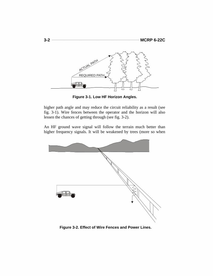
Long-distance, HF sky wave signals of more than several hundred kilo-meters are often best transmitted and received at angles just above thehorizon level. Obstacles on the horizon will cause the signal to travel a
3-2 _______________________________________________ MCRP 6-22C
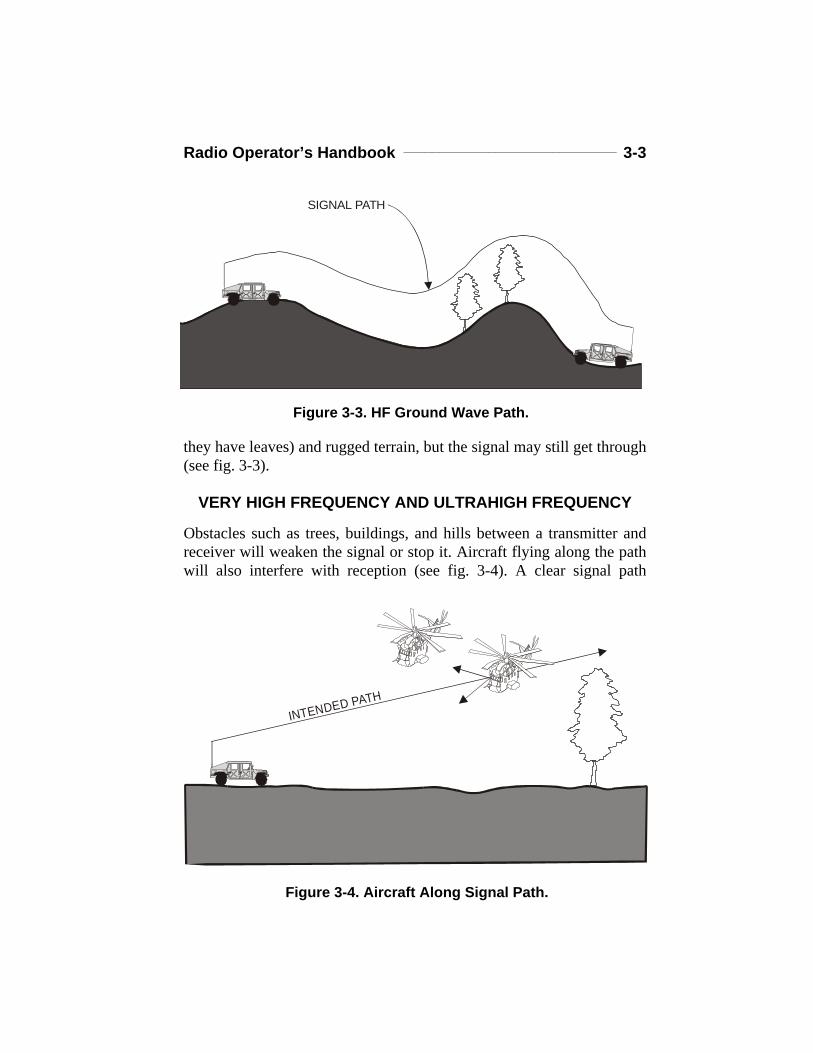
higher path angle and may reduce the circuit reliability as a result (seefig. 3-1). Wire fences between the operator and the horizon will alsolessen the chances of getting through (see fig. 3-2).
An HF ground wave signal will follow the terrain much better thanhigher frequency signals. It will be weakened by trees (more so when
ACTUAL PATH
REQUIRED PATH
Figure 3-1. Low HF Horizon Angles.
Figure 3-2. Effect of Wire Fences and Power Lines.
Radio Operator’s Handbook ______________________________ 3-3
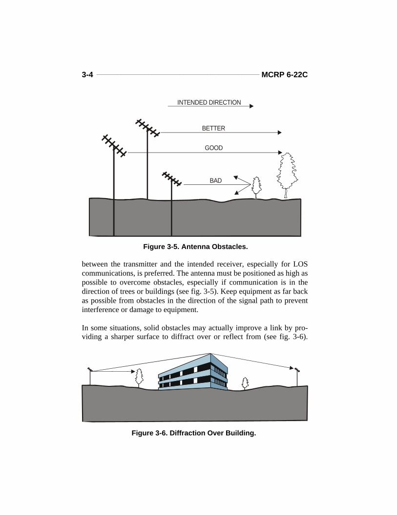
they have leaves) and rugged terrain, but the signal may still get through(see fig. 3-3).
VERY HIGH FREQUENCY AND ULTRAHIGH FREQUENCY
Obstacles such as trees, buildings, and hills between a transmitter andreceiver will weaken the signal or stop it. Aircraft flying along the pathwill also interfere with reception (see fig. 3-4). A clear signal path
INTENDED PATH
SIGNAL PATH
Figure 3-3. HF Ground Wave Path.
Figure 3-4. Aircraft Along Signal Path.
3-4 _______________________________________________ MCRP 6-22C
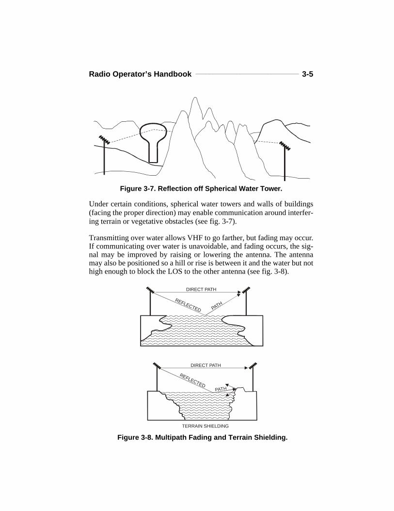
between the transmitter and the intended receiver, especially for LOScommunications, is preferred. The antenna must be positioned as high aspossible to overcome obstacles, especially if communication is in thedirection of trees or buildings (see fig. 3-5). Keep equipment as far backas possible from obstacles in the direction of the signal path to preventinterference or damage to equipment.
In some situations, solid obstacles may actually improve a link by pro-viding a sharper surface to diffract over or reflect from (see fig. 3-6).
INTENDED DIRECTION
BETTER
GOOD
BAD
Figure 3-5. Antenna Obstacles.
Figure 3-6. Diffraction Over Building.
Radio Operator’s Handbook ______________________________ 3-5
Under certain conditions, spherical water towers and walls of buildings(facing the proper direction) may enable communication around interfer-ing terrain or vegetative obstacles (see fig. 3-7).
Transmitting over water allows VHF to go farther, but fading may occur.If communicating over water is unavoidable, and fading occurs, the sig-nal may be improved by raising or lowering the antenna. The antennamay also be positioned so a hill or rise is between it and the water but nothigh enough to block the LOS to the other antenna (see fig. 3-8).
Figure 3-7. Reflection off Spherical Water Tower.
Figure 3-8. Multipath Fading and Terrain Shielding.TERRAIN SHIELDING
DIRECT PATH
REFLECTED PATH
DIRECT PATH
REFLECTED PATH

3-6 _______________________________________________ MCRP 6-22C
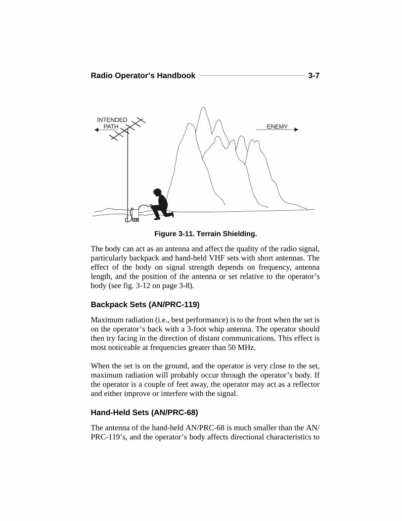
Nothing is more compromising to a unit’s location than an antenna farmstretched along a ridge line (see fig. 3-9). The enemy will realize that amajor command post is nearby. The advantage of placing an antenna ona ridge line is the ability to talk in many directions without land being inthe way. If communication is needed in only one direction—away fromthe enemy—put some terrain shielding between the antenna farm andthe enemy (see figures 3-10 and 3-11). This way, the enemy won’t beable to intercept communications or jam circuits as easily. However, it’snot always necessary to talk from hilltop to hilltop. Talking from hillsideto hillside or along the valley floor may be a better option in someinstances. The enemy will certainly have a harder time locating a unitthis way.
Figure 3-9. Ridge Line Antenna Farm.
Figure 3-10. Low Antenna Profile.
Radio Operator’s Handbook ______________________________ 3-7
The body can act as an antenna and affect the quality of the radio signal,particularly backpack and hand-held VHF sets with short antennas. Theeffect of the body on signal strength depends on frequency, antennalength, and the position of the antenna or set relative to the operator’sbody (see fig. 3-12 on page 3-8).
Backpack Sets (AN/PRC-119)
Maximum radiation (i.e., best performance) is to the front when the set ison the operator’s back with a 3-foot whip antenna. The operator shouldthen try facing in the direction of distant communications. This effect ismost noticeable at frequencies greater than 50 MHz.
When the set is on the ground, and the operator is very close to the set,maximum radiation will probably occur through the operator’s body. Ifthe operator is a couple of feet away, the operator may act as a reflectorand either improve or interfere with the signal.
Hand-Held Sets (AN/PRC-68)
The antenna of the hand-held AN/PRC-68 is much smaller than the AN/PRC-119’s, and the operator’s body affects directional characteristics to
INTENDED PATH
ENEMY
Figure 3-11. Terrain Shielding.
3-8 _______________________________________________ MCRP 6-22C
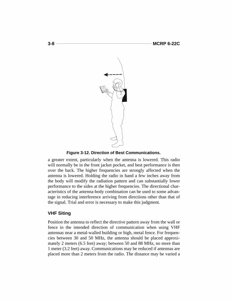
a greater extent, particularly when the antenna is lowered. This radiowill normally be in the front jacket pocket, and best performance is thenover the back. The higher frequencies are strongly affected when theantenna is lowered. Holding the radio in hand a few inches away fromthe body will modify the radiation pattern and can substantially lowerperformance to the sides at the higher frequencies. The directional char-acteristics of the antenna-body combination can be used to some advan-tage in reducing interference arriving from directions other than that ofthe signal. Trial and error is necessary to make this judgment.
VHF Siting
Position the antenna to reflect the directive pattern away from the wall orfence in the intended direction of communication when using VHFantennas near a metal-walled building or high, metal fence. For frequen-cies between 30 and 50 MHz, the antenna should be placed approxi-mately 2 meters (6.5 feet) away; between 50 and 88 MHz, no more than1 meter (3.2 feet) away. Communications may be reduced if antennas areplaced more than 2 meters from the radio. The distance may be varied a
Figure 3-12. Direction of Best Communications.
Radio Operator’s Handbook ______________________________ 3-9
foot or so in each direction, while receiving, to find the position wherethe signal is the strongest when setting up the equipment. If frequenciesare changed later, the optimum position will have to be redetermined atthat time by the same method.
UHF Siting
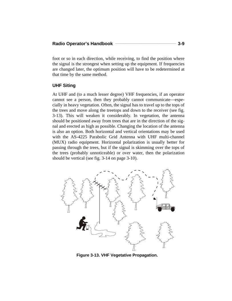
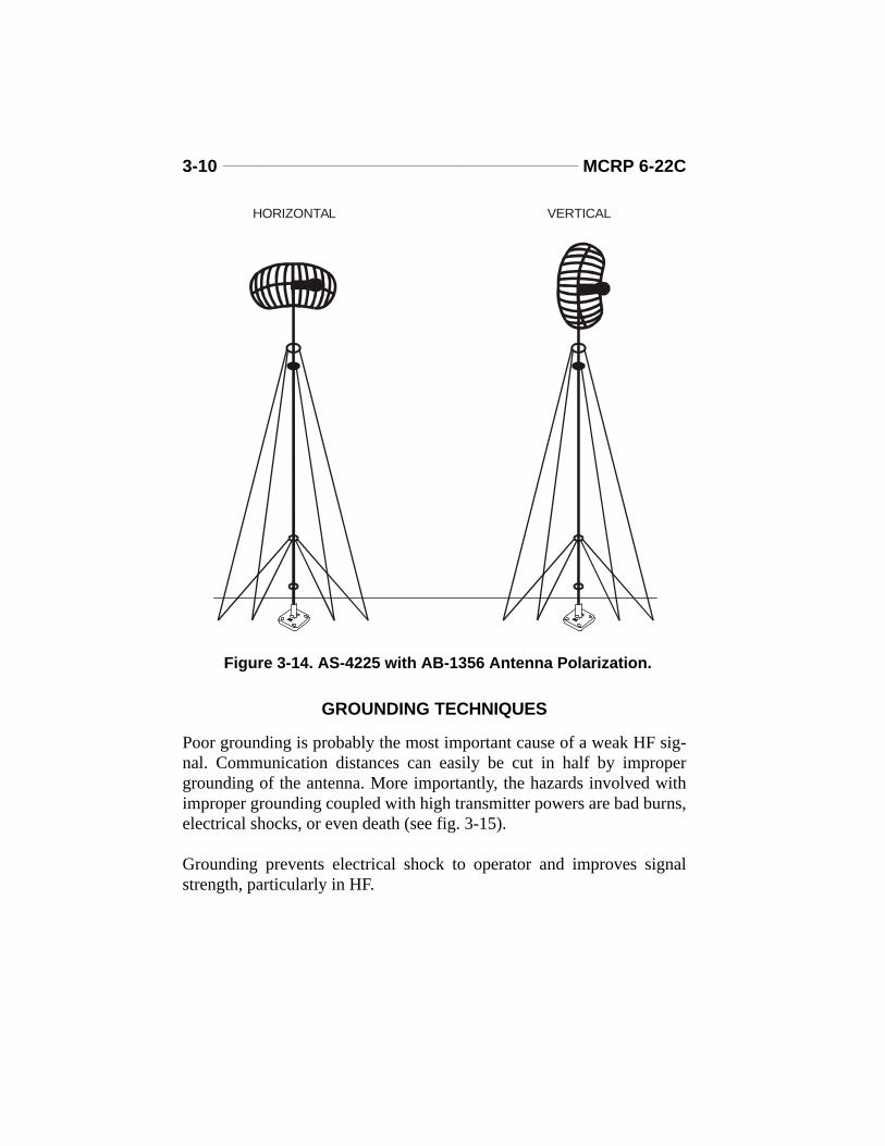
At UHF and (to a much lesser degree) VHF frequencies, if an operatorcannot see a person, then they probably cannot communicate—espe-cially in heavy vegetation. Often, the signal has to travel up to the tops ofthe trees and move along the treetops and down to the receiver (see fig.3-13). This will weaken it considerably. In vegetation, the antennashould be positioned away from trees that are in the direction of the sig-nal and erected as high as possible. Changing the location of the antennais also an option. Both horizontal and vertical orientations may be usedwith the AS-4225 Parabolic Grid Antenna with UHF multi-channel(MUX) radio equipment. Horizontal polarization is usually better forpassing through the trees, but if the signal is skimming over the tops ofthe trees (probably unnoticeable) or over water, then the polarizationshould be vertical (see fig. 3-14 on page 3-10).
Figure 3-13. VHF Vegetative Propagation.
3-10 ______________________________________________ MCRP 6-22C
GROUNDING TECHNIQUES
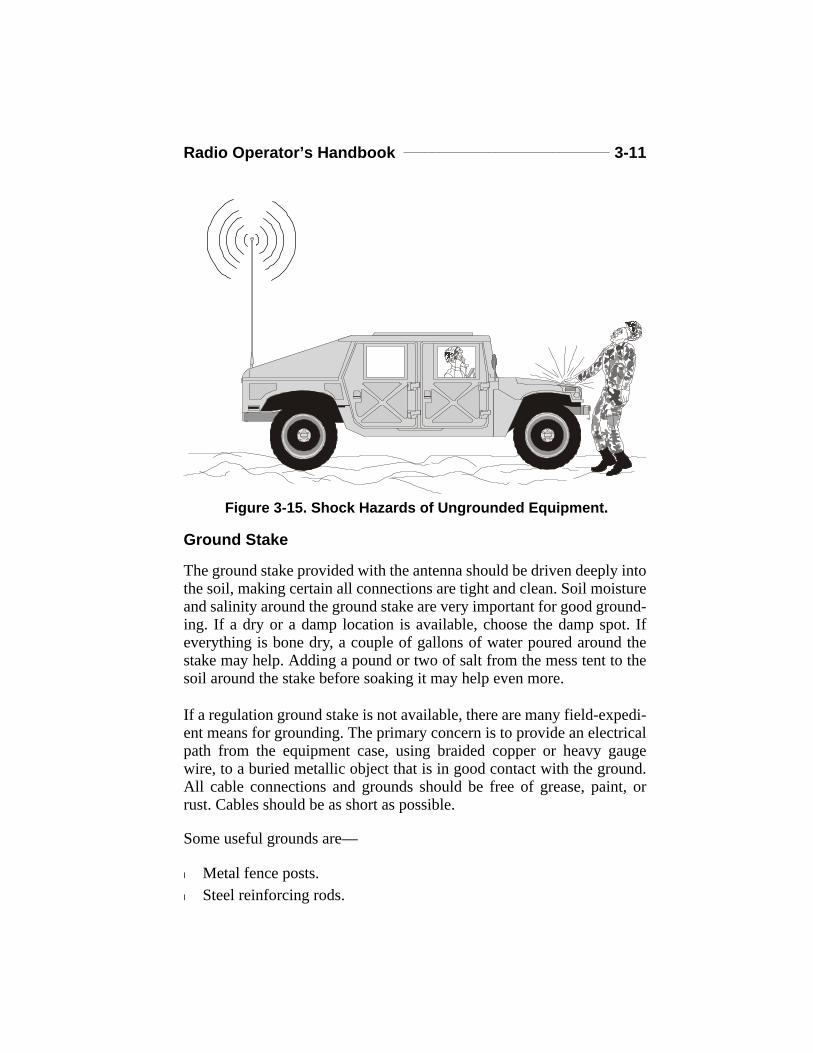
Poor grounding is probably the most important cause of a weak HF sig-nal. Communication distances can easily be cut in half by impropergrounding of the antenna. More importantly, the hazards involved withimproper grounding coupled with high transmitter powers are bad burns,electrical shocks, or even death (see fig. 3-15).
Grounding prevents electrical shock to operator and improves signalstrength, particularly in HF.
HORIZONTAL VERTICAL
Figure 3-14. AS-4225 with AB-1356 Antenna Polarization.
Radio Operator’s Handbook _____________________________ 3-11
Ground Stake
The ground stake provided with the antenna should be driven deeply intothe soil, making certain all connections are tight and clean. Soil moistureand salinity around the ground stake are very important for good ground-ing. If a dry or a damp location is available, choose the damp spot. Ifeverything is bone dry, a couple of gallons of water poured around thestake may help. Adding a pound or two of salt from the mess tent to thesoil around the stake before soaking it may help even more.
If a regulation ground stake is not available, there are many field-expedi-ent means for grounding. The primary concern is to provide an electricalpath from the equipment case, using braided copper or heavy gaugewire, to a buried metallic object that is in good contact with the ground.All cable connections and grounds should be free of grease, paint, orrust. Cables should be as short as possible.
Some useful grounds are—
l Metal fence posts.l Steel reinforcing rods.
Figure 3-15. Shock Hazards of Ungrounded Equipment.
3-12 ______________________________________________ MCRP 6-22C
l Metal pipes.l Metal plumbing (must not be connected to flammable liquid or gas).l Metal building frames.
Ground Radials
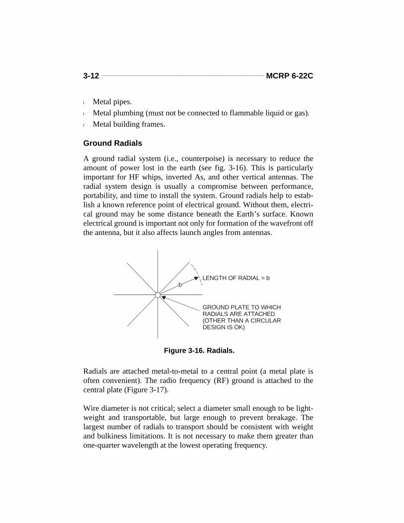
A ground radial system (i.e., counterpoise) is necessary to reduce theamount of power lost in the earth (see fig. 3-16). This is particularlyimportant for HF whips, inverted As, and other vertical antennas. Theradial system design is usually a compromise between performance,portability, and time to install the system. Ground radials help to estab-lish a known reference point of electrical ground. Without them, electri-cal ground may be some distance beneath the Earth’s surface. Knownelectrical ground is important not only for formation of the wavefront offthe antenna, but it also affects launch angles from antennas.
Radials are attached metal-to-metal to a central point (a metal plate isoften convenient). The radio frequency (RF) ground is attached to thecentral plate (Figure 3-17).
Wire diameter is not critical; select a diameter small enough to be light-weight and transportable, but large enough to prevent breakage. Thelargest number of radials to transport should be consistent with weightand bulkiness limitations. It is not necessary to make them greater thanone-quarter wavelength at the lowest operating frequency.
LENGTH OF RADIAL = b
GROUND PLATE TO WHICH RADIALS ARE ATTACHED(OTHER THAN A CIRCULARDESIGN IS OK)
b
Figure 3-16. Radials.

Radio Operator’s Handbook _____________________________ 3-13
One-quarter wavelength = 74.9 meters frequency (MHz)
Suggested dimensions:
If the site is semipermanent (i.e., several days or more), the number ofradials should be increased to 100, and their length doubled.
Make radial systems for each antenna prior to an operation. Short stakesat the ends may be used to hold them in position when deploying.Ground all radios, where possible.
5 meters (15-foot whip): N (number of radials) = at least 30(one every 12°)
b (length of radial) = 7 meters(23 feet)
10 meters (32-foot whip): N = at least 30b = 14 meters (46 feet)
WHIP ANTENNA
GROUND RADIALS
RF GROUND
STAKE (METAL OR WOOD)
Figure 3-17. Equipment Configuration.
(reverse blank)
Chapter 4
Antennas
This chapter will discuss high frequency and very high frequency anten-nas. Antenna designs that work for HF sometimes work for VHF andvice versa. The main difference is size; HF antennas are considerablylarger than VHF antennas. Ultrahigh frequency antennas are generallylimited to whips. When determining the best antenna to employ with acircuit, consult MCRP 6-22D for more detailed information on antennapropagation characteristics, as well as construction considerations andprocedures.
HIGH FREQUENCY ANTENNAS
Vertical Whip
A vertical whip antenna (i.e., whip) will most likely be used with an HFradio. The whip is particularly good for ground wave communications inmany directions at one time, at distances of 20 to 30 kilometers. Unfor-tunately, while it is radiating in all directions at the same time, it is alsopicking up interference from all directions. It is useless if using sky waveover a distance of 100 kilometers, because of the high radiation anglesrequired. (NOTE: Launch angles off vertically polarized whip antennasare maximum below 45°.) A vertical whip’s performance by sky wave,however, improves with increased path distances.
A vehicle-mounted whip, tied down fairly close to the vehicle, may beefficiently employed in short- and intermediate-distance HF sky wavecommunications. A whip, tied back only a little, may be useful in long-distance HF sky wave applications.
Sloping Wire
If an HF circuit is only a single point-to-point ground link or a groundwave net with all other terminals being located in the same direction, a
4-2 _______________________________________________ MCRP 6-22C
sloping wire may be used, if available. The radiating length of the AT-984 “Fishreel” antenna (a 45-foot long, wire antenna which can be usedwith the AN/PRC-104) can be varied by either connecting or disconnect-ing the alligator clips. (Antenna length is measured from the radio equip-ment.) See Table 4-1 to determine how long an antenna should be cut toform an assigned frequency.
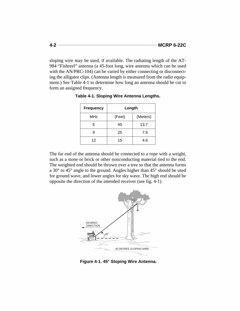
The far end of the antenna should be connected to a rope with a weight,such as a stone or brick or other nonconducting material tied to the end.The weighted end should be thrown over a tree so that the antenna formsa 30° to 45° angle to the ground. Angles higher than 45° should be usedfor ground wave, and lower angles for sky wave. The high end should beopposite the direction of the intended receiver (see fig. 4-1).
Table 4-1. Sloping Wire Antenna Lengths.
Frequency Length
MHz (Feet) (Meters)
5 45 13.7
9 25 7.6
12 15 4.6
DESIREDDIRECTION
45
45 DEGREE SLOPING WIRE
Figure 4-1. 45° Sloping Wire Antenna.

Radio Operator’s Handbook ______________________________ 4-3
AS-2259 Near-Vertical Incidence
Another HF antenna is the AS-2259 (see fig. 4-2). Although not suitablefor frequencies under 3.5 MHz, this antenna can be used for both groundwave and sky wave. The AS-2259 will often enable an operator to com-municate in a skip zone when a whip antenna will not. In addition, it cansometimes be used effectively to communicate by sky wave over a hillor mountain obstacle that would otherwise block a ground wave signal.More detailed information regarding HF NVIS antennas can be found inMCRP 6-22D.
Horizontal Half -Wave Dipole (Doublet)
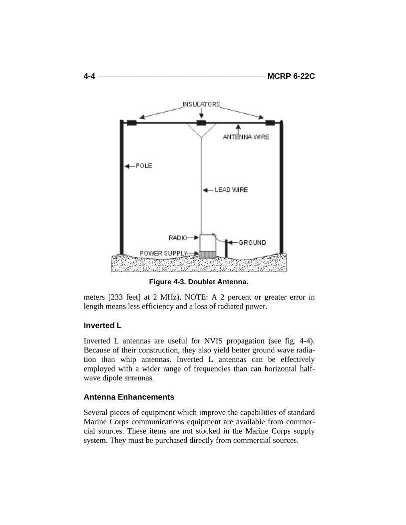
The horizontal half-wave dipole (also known as the doublet) is fre-quently used for short to medium HF sky wave paths (up to about 1,500kilometers). It is usually installed at one-quarter wavelength of the oper-ating frequency above ground (see fig. 4-3 on page 4-4). The majordrawback of this antenna is the unusually long length required (up to 71
Figure 4-2. AS-2259.
4-4 _______________________________________________ MCRP 6-22C
meters [233 feet] at 2 MHz). NOTE: A 2 percent or greater error inlength means less efficiency and a loss of radiated power.
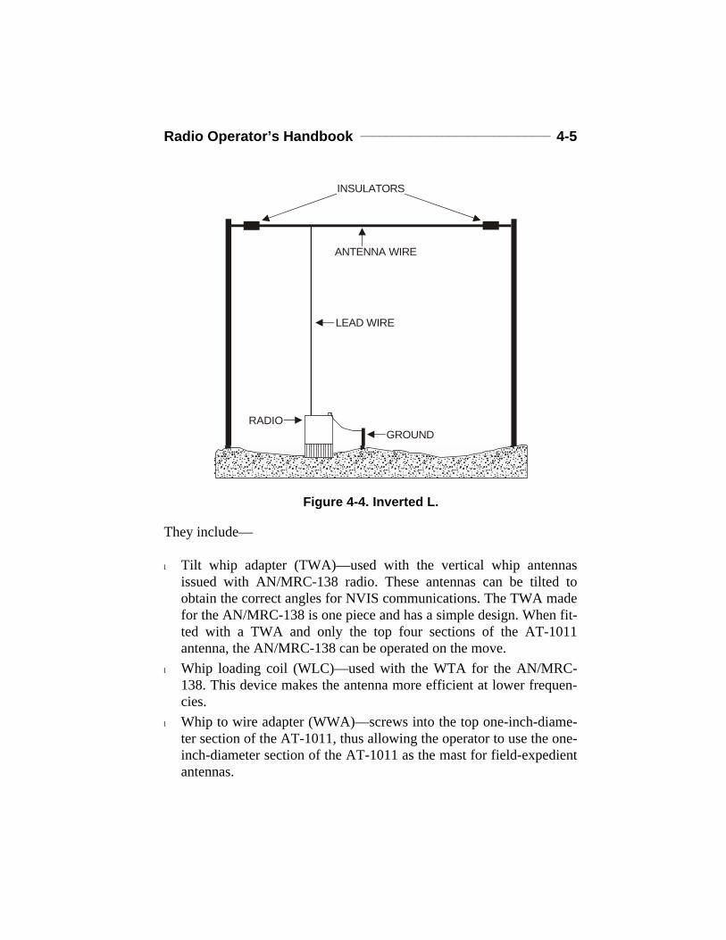
Inverted L
Inverted L antennas are useful for NVIS propagation (see fig. 4-4).Because of their construction, they also yield better ground wave radia-tion than whip antennas. Inverted L antennas can be effectivelyemployed with a wider range of frequencies than can horizontal half-wave dipole antennas.
Antenna Enhancements
Several pieces of equipment which improve the capabilities of standardMarine Corps communications equipment are available from commer-cial sources. These items are not stocked in the Marine Corps supplysystem. They must be purchased directly from commercial sources.
Figure 4-3. Doublet Antenna.
Radio Operator’s Handbook ______________________________ 4-5
They include—
l Tilt whip adapter (TWA)—used with the vertical whip antennasissued with AN/MRC-138 radio. These antennas can be tilted toobtain the correct angles for NVIS communications. The TWA madefor the AN/MRC-138 is one piece and has a simple design. When fit-ted with a TWA and only the top four sections of the AT-1011antenna, the AN/MRC-138 can be operated on the move.
l Whip loading coil (WLC)—used with the WTA for the AN/MRC-138. This device makes the antenna more efficient at lower frequen-cies.
l Whip to wire adapter (WWA)—screws into the top one-inch-diame-ter section of the AT-1011, thus allowing the operator to use the one-inch-diameter section of the AT-1011 as the mast for field-expedientantennas.
INSULATORS
ANTENNA WIRE
RADIOGROUND
LEAD WIRE
Figure 4-4. Inverted L.

4-6 _______________________________________________ MCRP 6-22C
l Whip-base adapter (WBA)—allows the whip antennas for Army HFradios to be used with Marine Corps HF radios. The whip antennasfor Army HF radios are of a different size than the whip antennas forMarine Corps HF radios.
For further information about commercial equipment which can improvethe capabilities of Marine Corps radios, contact the G-6/S-6 sections ofhigher headquarters.
VERY HIGH FREQUENCY ANTENNAS
OE-254
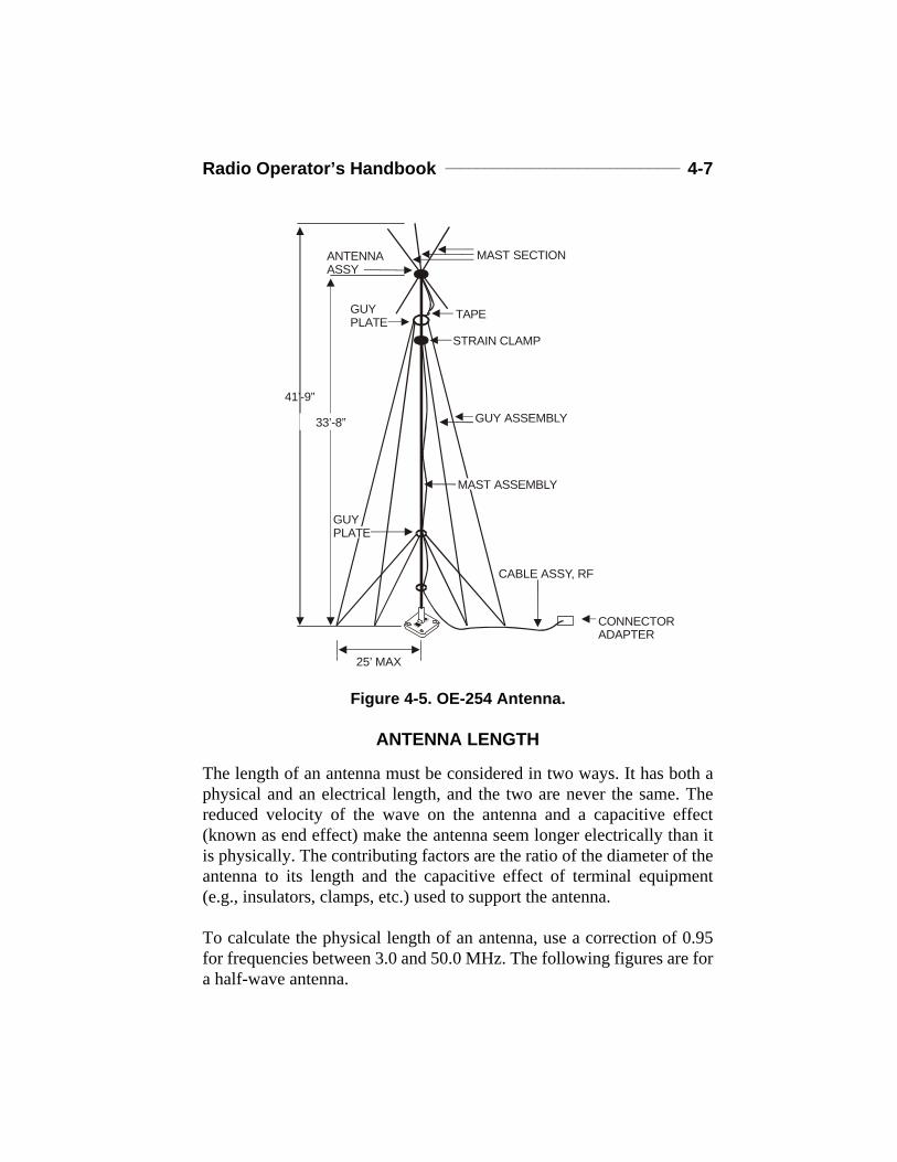
This antenna is used with VHF-FM radios to increase the operatingrange beyond that of a normal whip. The two elements hanging downfrom the antenna form a ground-plane similar to the ground radials dis-cussed in chapter 3. The effect is to act as an artificial ground and greatlyincrease the signal range. The antenna radiates in all directions at thesame time. The OE-254’s elements allow it to tune to frequenciesbetween 30 and 88 MHz without manually adjusting either the ground-plane or radiating elements’ length. Figure 4-5 illustrates the OE-254antenna.
Vertical Whip
VHF whip antennas are usually limited in range from 15 to 20 miles. Awhip antenna is omnidirectional; therefore, it has the potential to pro-duce a great deal of radio-wave interference with the radios in the area. Itis important when using a whip antenna or any antenna to keep maxi-mum distance between antennas. Use of hills and other terrain featuresto block off unwanted signals will improve desired signal strength.When using whip antennas with backpack or hand-held equipment, bodyposition may increase the transmitted and received signal. This isbecause the human body acts as an antenna. If experiencing communica-tion problems, the operator should try facing in different directions toimprove the reception of the signal.
Radio Operator’s Handbook ______________________________ 4-7
ANTENNA LENGTH
The length of an antenna must be considered in two ways. It has both aphysical and an electrical length, and the two are never the same. Thereduced velocity of the wave on the antenna and a capacitive effect(known as end effect) make the antenna seem longer electrically than itis physically. The contributing factors are the ratio of the diameter of theantenna to its length and the capacitive effect of terminal equipment(e.g., insulators, clamps, etc.) used to support the antenna.
To calculate the physical length of an antenna, use a correction of 0.95for frequencies between 3.0 and 50.0 MHz. The following figures are fora half-wave antenna.
Figure 4-5. OE-254 Antenna.
MAST SECTION
TAPE
STRAIN CLAMP
GUY ASSEMBLY
CABLE ASSY, RF
CONNECTORADAPTER
ANTENNA ASSY
GUY PLATE
41’-9”
33’-8”
25’ MAX
MAST ASSEMBLY
GUY PLATE
4-8 _______________________________________________ MCRP 6-22C
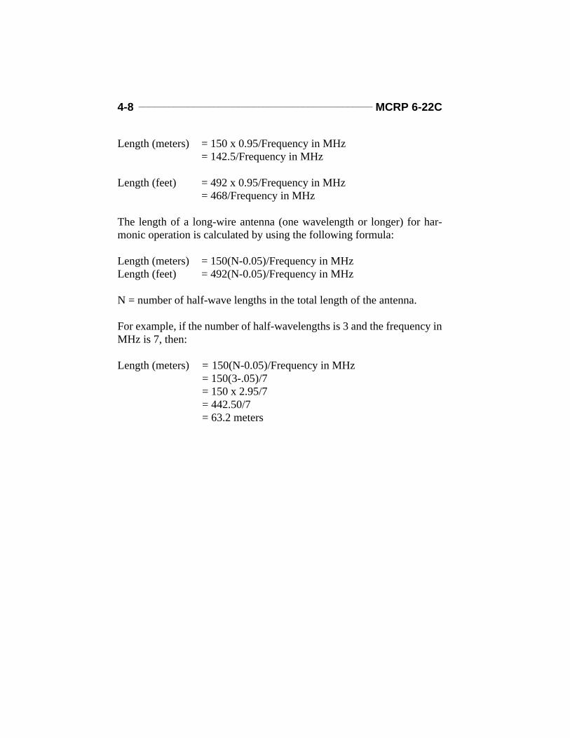
Length (meters) = 150 x 0.95/Frequency in MHz = 142.5/Frequency in MHz
Length (feet) = 492 x 0.95/Frequency in MHz= 468/Frequency in MHz
The length of a long-wire antenna (one wavelength or longer) for har-monic operation is calculated by using the following formula:
Length (meters) = 150(N-0.05)/Frequency in MHzLength (feet) = 492(N-0.05)/Frequency in MHz
N = number of half-wave lengths in the total length of the antenna.
For example, if the number of half-wavelengths is 3 and the frequency inMHz is 7, then:
Length (meters) = 150(N-0.05)/Frequency in MHz = 150(3-.05)/7= 150 x 2.95/7= 442.50/7= 63.2 meters
Chapter 5
Interference
Radio frequency interference is always present in a military environ-ment. It may come from a single source or a combination of manysources including natural or manmade frequency interference, poorequipment condition, improper equipment usage, frequency interfer-ence, use of unauthorized frequencies, and frequency reuse.
NATURAL INTERFERENCE
Natural radio noise has two principal sources: thunderstorms (atmo-spheric noise) and stars (galactic noise). It is especially noticeable atnight when the lower frequencies propagate farther than in the daytime.The only way to reduce this type of interference is to use a directionalantenna to prevent receiving the interference from all directions. How-ever, this will not eliminate the noise coming from the direction of thereceived signal. Use of a higher frequency will also help, although if asky wave circuit is used, care must be exercised not to pick the highestfrequency at which the signal will be refracted to Earth by the iono-sphere (i.e., the critical frequency).
MANMADE INTERFERENCE
Most manmade interference comes from electrical sources such aspower generators, alarm systems, power lines, auto ignition, fluorescentlighting, faulty electrical relay contacts, and electrified railroads. Man-made interference also includes enemy jammers (see chapter 7). The keyto combating this form of interference is to isolate communicationsequipment from manmade interference. The interference from knownsources such as generators can be greatly reduced if an antenna is posi-tioned so that an obstacle (e.g., a hill) is between it and the source. Thismust be done so that the same obstacle will not block the intended radiopath. If the interference is not coming from the same direction as theintended signal, then a directional antenna should be used.
5-2 _______________________________________________ MCRP 6-22C
POOR EQUIPMENT CONDITION AND IMPROPER USAGE
The condition of radio equipment and how it is being used may result ininterference. There are several steps that should be taken to lessen thispossibility. These include making certain that shielded cables are usedwhere required, ensuring connectors are properly connected to cables,and making sure that antennas within a group are as far apart as possible.All antenna leads (transmission lines), power lines, and telephone linesshould be as short as possible when they are on the ground and shouldnot cross. If lines do cross, they must cross at 90° angles to each other,and they must be separated from each other by standoffs. Lines threadedthrough the trees near an antenna serve as pipelines for interference toand from antennas. Finally, ensure that all radio equipment is grounded.
FREQUENCY INTERFERENCE AND INTERMODULATION
Frequency interference is one of the easiest communications problems toprevent, but it must be done by the CIS officer, CIS chief, and frequencymanager during the development of the CIS plan. This type of interfer-ence is caused primarily by two radio transmitters using the same fre-quency, but it can also happen when different frequencies are used. Mostof these problems can be eliminated by good frequency planning. How-ever, if frequency interference does occur the following steps can betaken to improve communications:
l Identify the source of the interference. If it is a VHF or HF groundwave transmission, it will probably be within the immediate area andwill only occur when the offending transmitter is keyed. The otheroperator is probably transmitting on a different frequency and has noway of knowing that he is interfering with anyone else’s ability totransmit.
l Get the interfering operator to lower their transmitter power as longas it does not degrade their circuit.
l Put as much distance as possible between the affected unit’s equip-ment. This may involve using a hill or other object to block the signal.
l Change to a directional antenna.
Radio Operator’s Handbook ______________________________ 5-3
l Remember that the receiver of interference may also cause someoneelse interference and, whenever possible, should lower his power anduse a directional antenna.
l Report interference to the CIS officer or CIS chief.
USE OF UNAUTHORIZED FREQUENCIES
There is one final source of frequency interference: the use of unautho-rized frequencies. This practice is illegal and has the potential to disrupta carefully engineered frequency plan, introduce interference to otherfrequencies and circuits, and prevent other units from fulfilling theirmission. Radio operators should never use unauthorized frequencies.
FREQUENCY REUSE
There are not enough radio frequencies available for all radio operatorsto have their own channel. When HF propagation conditions are favor-able, Marines may discover that their radio frequency is being used byforeign or United States military personnel in other countries. VHF FMfrequencies often have to be reused within the same operation by morethan one unit. The exercise frequency manager will try to make certainthat users of the same frequency are as far away as possible from eachother, but some units (United States Marine Corps and Army, in particu-lar) will join at some stage in the operation. When this occurs, the firstcommon, higher headquarters should be informed to settle the problem.
(reverse blank)
Chapter 6
Radio Operations UnderUnusual Conditions
OPERATIONS IN DESERT AREAS
Capabilities and Limitations
SCR is usually the primary means of communications in the desert. Itcan be employed effectively in desert climate and terrain to provide thehighly mobile means of communications demanded by widely dispersedforces. However, desert terrain provides poor electrical ground, andcounterpoises are needed to improve operation.
Techniques for Operations
For the best operation in the desert, radio antennas should be located onthe highest terrain available. Transmitters using whip antennas in thedesert will lose one-fifth to one-third of their normal range because ofthe poor electrical grounding characteristics of desert terrain. For thisreason, it is important to use complete antenna systems such as horizon-tal dipoles and vertical antennas with adequate counterpoises.
Equipment Considerations
Some SCRs automatically switch on their second blower fan if theirinternal temperature rises too high. Normally, this happens only in tem-perate climates when the radios are transmitting. This may disturbMarines unaccustomed to radio operation in the desert environment.Operation of the second fan, however, is quite normal. RF power ampli-fiers used in AM and SSB sets are liable to overheat severely and burnout. They should be turned on only when necessary (signal reception isnot affected). Since the RF power amplifiers take approximately 90 sec-onds to reach the operating mode, the standing operating procedure(SOP) of units using the equipment should allow for delays in replying.

6-2 _______________________________________________ MCRP 6-22C
Dust affects communications equipment such as SSB/AM RF poweramplifiers. Dust covers should be used whenever possible. Somereceiver-transmitter units have ventilating ports and channels that canget clogged with dust. These must be checked regularly and kept clean toprevent overheating.
Batteries. Wet cell batteries do not hold their charge efficiently in intenseheat. Electrolyte evaporates rapidly and should be checked weekly(more often, if warranted). Add distilled water as needed. Extra contain-ers of distilled water should be carried in the vehicle. Maintenance ofvehicle batteries, beyond adding water, must be done only by authorizedmotor-transport personnel according to applicable Marine Corps Ordersand SOPs. Dry battery supplies must be increased, since hot weathercauses batteries to fail more rapidly.
Electrical Insulation. Wind-blown sand and grit will damage electricalwire insulation over a period of time. All cables that are likely to bedamaged should be protected with tape before insulation becomes worn.Sand will also find its way into parts of items such as “spaghetti cord”plugs, either preventing electrical contact or making it impossible to jointhe plugs. Carry a brush, such as an old toothbrush, and use it to cleansuch items before they are joined.
Condensation. In deserts with relatively high dew levels and highhumidity, overnight condensation can occur wherever surfaces (such asmetals exposed to air) are cooler than the air temperature. This conden-sation can affect electrical plugs, jacks, and connectors. All connectorslikely to be affected by condensation should be taped to prevent moisturefrom contaminating the contacts. Plugs should be dried before insertingthem into equipment jacks. Excessive moisture or dew should be driedfrom antenna connectors to prevent arcing.
Static Electricity. Static electricity is prevalent in the desert. It is causedby many factors, e.g., wind-blown dust particles. Extremely low humid-ity contributes to static discharges between charged particles. Poorgrounding conditions exacerbate the problem. Be sure to tape all sharpedges (tips) of antennas to cut down on wind-caused static dischargesand the accompanying noise. If you are operating from a fixed position,

Radio Operator’s Handbook ______________________________ 6-3
ensure that equipment is properly grounded. Since static-caused noisediminishes with an increase in frequency, use the highest frequenciesthat are available and authorized.
Maintenance Improvement
In desert areas, the maintenance of SCRs becomes more difficultbecause of the large amounts of sand, dust, or dirt that enter the equip-ment. Radios equipped with servomechanisms are particularly affected.To reduce maintenance downtime, keep the radios in dustproof contain-ers as much as possible. It is also important to keep air vent filters cleanto allow cool air to circulate to prevent overheating. Preventive mainte-nance checks should be made frequently. Also, keep a close check onlubricated parts of the equipment. If dust and dirt mix with the lubri-cants, moving parts may be damaged.
OPERATIONS IN JUNGLE AREAS
Capabilities and Limitations
SCR communications in jungle areas must be carefully planned becausethe dense jungle growth significantly reduces the range of radio trans-mission. However, since SCR can be deployed in many configurations,especially manpacked, it is a valuable communications asset. Mobility isalso an advantage of SCR. The capabilities and limitations of SCR mustbe carefully considered when used by forces in a jungle environment.
Climate and density of jungle growth limits SCR communications injungle areas. The hot and humid climate increases the maintenance prob-lems of keeping equipment operable. Thick jungle growth acts as a verti-cally polarized absorbing screen for RF energy that reduces transmissionrange. Therefore, increased emphasis on maintenance and antenna sitingis necessary when operating in jungle areas.
Techniques for Operations
The main problem in establishing SCR communications in jungle areasis the siting of the antenna.
6-4 _______________________________________________ MCRP 6-22C
Apply the following techniques to improve communications in thejungle:
l Antennas should be located in clearings on the edge farthest from thedistant station and as high as possible.
l Antenna cables and connectors should be kept off the ground tolessen the effects of moisture, fungus, and insects. This also applies toall power and telephone cables.
l Complete antenna systems, such as ground planes and dipoles, aremore effective than fractional wavelength whip antennas.
l Vegetation must be cleared from antenna sites. If an antenna touchesany foliage, especially wet foliage, the signal will be grounded.
l Vegetation, particularly when wet, acts like a vertically polarizedscreen and absorbs much of a vertically polarized signal. Horizontallypolarized antennas are preferred to vertically polarized antennas.
Maintenance Improvement
Because of moisture and fungus, the maintenance of SCR in tropical cli-mates is more difficult than in temperate climates. The high relativehumidity causes condensation to form on the equipment and encouragesthe growth of fungus. Operators and maintenance personnel shouldcheck the appropriate TMs for any special maintenance requirements.Some techniques for improving maintenance in jungle areas are—
l Keep the equipment as dry as possible and in lighted areas to retardfungus growth.
l Keep all air vents clear of obstructions so air can circulate to cool anddry the equipment.
l Keep connectors, cables, and bare metal parts as free of fungusgrowth as possible. Use moisture fungusproofing paint (MFP) to pro-tect equipment after repairs are made or when equipment is damagedor scratched.
Radio Operator’s Handbook ______________________________ 6-5
High Frequency Expedient Antennas
Dismounted patrols and units of company size and below can greatlyimprove their ability to communicate in the jungle by using expedientantennas. While moving, they are generally restricted to using the shortand long antennas which come with the radios. However, when they arenot moving, these expedient antennas will allow them to broadcast far-ther and receive more clearly.
Note: An antenna that is not “tuned” or “cut” to the operating fre-quency is not as effective as the whips that are supplied with the radio.
Circuits inside the radio “load” the whips properly so that they are“tuned” to give maximum output. Whips are not as effective as a tuneddoublet or tuned ground-plane, but the doublet or ground-plane must betuned to the operating frequency.
OPERATIONS IN A COLD WEATHER ENVIRONMENT
Capabilities and Limitations
SCR equipment has certain capabilities and limitations that must becarefully considered when operating in extremely cold areas. However,in spite of significant limitations, SCR is the normal means of communi-cations in such areas.
One of the most important capabilities of SCR in cold weather areas isits versatility. Vehicular-mounted radios can be moved relatively easilyto almost any point where it is possible to install a command headquar-ters. Smaller, manpacked radios can be carried to any point accessible byfoot or aircraft.
A limitation on radio communications that radio operators must expectin extremely cold areas is interference by ionospheric disturbances.These disturbances, known as ionospheric storms, have a definitedegrading effect on sky wave propagation. Moreover, either the stormsor the auroral (e.g., Northern Lights) activity can cause complete failureof radio communications. Some frequencies may be blocked out com-pletely by static for extended periods of time during storm activity.
6-6 _______________________________________________ MCRP 6-22C
Fading, caused by changes in the density and height of the ionosphere,can also occur and may last from minutes to weeks. The occurrence ofthese disturbances is difficult to predict. When they occur, the use ofalternate frequencies and a greater reliance on FM or other means ofcommunications are required.
Techniques for Operations
Whenever possible, SCR for tactical operations in cold weather areasshould be installed in vehicles to reduce the problem of transportationand shelter for operators. This will also help solve some of the groundingand antenna installation problems caused by the climate.
Because of permafrost and deep snow, it is difficult to establish goodelectrical grounding in extremely cold areas. The conductivity of frozenground is often too low to provide good ground wave propagation. Toimprove ground wave operation, use a counterpoise to offset the degrad-ing effects of poor electrical ground conductivity. Remember to install acounterpoise high enough above the ground so that it will not be coveredby snow.
In general, antenna installation in arcticlike areas presents no serious dif-ficulties. However, installing some antennas may take longer because ofadverse working conditions. A few tips for installing antennas inextremely cold areas are—
l Mast sections and antenna cables must be handled carefully sincethey become brittle in very low temperatures.
l Antenna cables should be constructed overhead to prevent damagefrom heavy snow and frost, whenever possible. Nylon rope guys, ifavailable, should be used in preference to cotton or hemp becausenylon ropes do not readily absorb moisture and are less likely tofreeze and break.
l Antennas should have extra guy wires, supports, and anchor stakes towithstand heavy ice and wind loading.
Some Marine Corps radios that are adjusted to a particular frequency ina relatively warm place may drift off frequency when exposed to
Radio Operator’s Handbook ______________________________ 6-7
extreme cold. Low battery voltage can also cause frequency drift. Whenpossible, allow a radio to warm up several minutes before placing it intooperation. Since extreme cold tends to lower output voltage of a dry bat-tery, try warming the battery with body heat before operating the radioset. This minimizes frequency drift. Flakes or pellets of highly electri-cally charged snow are sometimes experienced in northern regions.When these particles strike the antenna, the resulting electrical dischargecauses a high-pitched static roar that can blanket all frequencies. Toovercome this static, antenna elements can be covered with polystyrenetape and shellac.
Maintenance Improvement
The maintenance of SCR equipment in extreme cold presents many dif-ficulties. Radios must be protected from blowing snow, since snow willfreeze to dials and knobs and blow into the wiring to cause shorts andgrounds. Cords and cables must be handled carefully since they may losetheir flexibility in extreme cold. All radio equipment and power unitsmust be properly winterized. Check the appropriate technical manual(TM) for winterization procedures. A few tips for maintenance in arcticareas are discussed in the following paragraphs.
Power Units. As the temperature goes down, it becomes increasingly dif-ficult to operate and maintain generators. They should be protected asmuch as possible from the weather.
Batteries. The effect of cold weather on wet and dry cell batteriesdepends upon the type and kind of battery, the load on the battery, theparticular use of the battery, and the degree of exposure to cold tempera-tures.
Shock Damage. Damage may occur to vehicular SCR by the jolting ofthe vehicle. Most synthetic rubber shock mounts become stiff and brittlein extreme cold and fail to cushion equipment. Check the shock mountsfrequently and change them, as required.
Winterization. Check the TMs for the SCR and power source to see ifthere are special precautions for operation in extremely cold climates.
6-8 _______________________________________________ MCRP 6-22C
For example, normal lubricants may solidify and permit damage or mal-functions. They must be replaced with the recommended arctic lubri-cants.
Microphones. Moisture from your breath may freeze on the perforatedcover plate of your microphone. Use standard microphone covers to pre-vent this. If standard covers are not available, improvise a suitable coverfrom rubber or cellophane membranes or from rayon or nylon cloth.
Breathing and Sweating. A SCR generates heat when it is operated.When it is turned off, the air inside cools and contracts and draws coldair into the set from the outside. This is called breathing. When a radiobreathes, and the still-hot parts come in contact with subzero air, theglass, plastic, and ceramic parts of the set may cool too rapidly andbreak.
When cold equipment is brought suddenly into contact with warm air,moisture will condense on the equipment parts. This is called sweating.Before cold equipment is brought into a heated area, it should bewrapped in a blanket or parka to ensure that it will warm gradually toreduce sweating. Equipment must be thoroughly dry before it is takenback out into the cold air or the moisture will freeze.
Vehicular-Mounted Radios. These radios present special problems duringwinter operations because of their continuous exposure to the elements.Proper starting procedures must be observed. The radio’s power switchmust be off prior to starting the vehicle; this is a particularly criticalrequirement when vehicles are slave started. If the radio is cold soakedfrom prolonged shutdown, frost may have collected inside the radio andcould cause circuit arcing. Hence, time should be allowed for the vehicleheater to warm the radio sufficiently that any frost collected within theradio has a chance to thaw. This may take up to an hour. Once the radiohas been turned on, it should warm up for approximately 15 minutesbefore transmitting or changing frequencies. This allows components tostabilize. If a vehicle is operated at a low idle with radios, heater, andlights on, the batteries may run down. Before increasing engine revolu-tions per minute to charge the batteries, radios should be turned off toavoid an excessive power surge. A light coat of silicon compound on
Radio Operator’s Handbook ______________________________ 6-9
antenna mast connections helps to keep them from freezing together andbecoming hard to dismantle.
OPERATIONS IN MOUNTAINOUS AREAS
Capabilities and Limitations
Operation of SCRs in mountainous areas has many of the same problemsas in northern or cold weather areas. Also, the mountainous terrainmakes the selection of transmission sites a critical task. In addition, theterrain restrictions encountered frequently make radio relay stations nec-essary for good communications.
Maintenance Improvement
Because of terrain obstacles, SCR transmissions will frequently have tobe by line of sight. Also, the ground in mountainous areas is often a poorelectrical conductor. Thus, a complete antenna system, such as a dipoleor ground-plane antenna with a counterpoise, should be used. The main-tenance procedures required in mountainous areas are very often thesame as maintenance in northern or cold weather areas. The varied orseasonal temperature and climatic conditions in mountainous areas makeflexible maintenance planning a necessity.
OPERATIONS IN SPECIAL ENVIRONMENTS
Urbanized Terrain
SCR communications in urbanized terrain poses special problems. Someproblems are similar to those encountered in mountainous areas. Thereare problems of obstacles blocking transmission paths. There is the prob-lem of poor electrical conductivity because of pavement surfaces. Thereis also the problem of commercial power-line interference. VHF radiosare not as effective in urbanized terrain as they are in some other areas.The power output and operating frequencies of these VHF radios requirea line of sight between antennas. Line of sight at street level is notalways possible in built-up areas.
6-10 ______________________________________________ MCRP 6-22C
HF radios do not require or rely on line of sight as much as VHF radiosbecause operating frequencies are lower, and power output is greater.The problem is that HF radios are not organic to small units. To over-come this, the VHF signals must be retransmitted.
Retransmission stations in aerial platforms can provide the most effec-tive means if they are available. Organic retransmission is more likely tobe used. The antenna should be hidden or blended in with surroundings.This will help prevent the enemy from using it as a landmark to “homein” his artillery bombardment. Antennas can be concealed by water tow-ers, existing civilian antennas, or steeples.
The following steps should also be taken within urbanized terrain:
l Park radio-equipped vehicles inside buildings for cover and conceal-ment.
l Dismount radio equipment and install it inside buildings (in base-ment, if available).
l Place generators against buildings or under sheds to decrease noiseand provide concealment (adequate ventilation must be provided toprevent heat buildup and subsequent failure of generator).
Nuclear, Biological, and Chemical Environment
One of the realities of fighting on the modern battlefield is the presenceof nuclear weapons. The explosion of a nuclear weapon causes a tremen-dous blast, followed by intense heat and strong radiation. The ionizationof the atmosphere by a nuclear explosion will have degrading effects oncommunications because of static and the disruption of the ionosphere.
Another effect of a nuclear explosion that is an even greater danger toradio communications is the electromagnetic pulse (EMP). EMP is astrong pulse of electromagnetic radiation, many times stronger than thestatic pulse generated by lightning. This pulse can enter the radiothrough the antenna system, power connections, and signal input con-nections. In the equipment, the pulse can break down circuit componentssuch as transistors, diodes, and integrated circuits. It can melt capacitors,inductors, and transformers. EMP can destroy a radio.
Radio Operator’s Handbook _____________________________ 6-11
Defensive measures against EMP call for proper maintenance, particu-larly the shielding of equipment. When the equipment is not in use, allantennas and cables should be removed to decrease the effect of EMP onthe equipment. Effective grounding is necessary to reduce effect of EMP.EMP is a danger to SCR equipment, but contamination is a danger toMarines. Contamination from any portion of the nuclear, biological, andchemical (NBC) environment has adverse effects on both equipment andpersonnel.
(reverse blank)
Chapter 7
Electronic Warfare
Electronic warfare (EW) is the military action involving the use of elec-tromagnetic energy (i.e., radio frequency waves) to attack personnel,facilities, or equipment with the intent of degrading, neutralizing, ordestroying enemy combat capability. EW includes electronic attack(EA), electronic protection (EP), and electronic warfare support (ES).
EA includes actions taken to prevent or reduce the enemy’s effective useof the electromagnetic spectrum and employment of weapons that useelectromagnetic or directed energy. EP represents actions taken to pro-tect personnel, facilities, and equipment from any effects of friendly orenemy employment of electronic warfare that degrade, neutralize, ordestroy friendly combat capability. ES involves actions taken by, orunder direct control of, an operational commander to search for, inter-cept, identify, and locate sources of intentional or unintentional radiatedelectromagnetic energy for the purpose of immediate threat recognition.Each radio operator must be aware of what the enemy will try to do. Theenemy is well equipped to conduct EW, and the different techniques theenemy uses have specific purposes in the enemy’s EW effort.
ELECTRONIC ATTACK TECHNIQUES
Enemy forces employ a large number of radio direction finder (RDF)sets and communications intelligence (COMINT) analysts to exploitfriendly use of the electromagnetic spectrum. The enemy’s goal is tolocate and destroy as many command and control, fire support, and intel-ligence sites as possible during the first critical phase of the battle. Whenthe enemy locates sites that the enemy cannot or does not want todestroy, these sites become prime targets for imitative electronic decep-tion (IED) or jamming. Imitative electronic deception is the enemy’s useof a compatible radio and a language expert to enter a friendly radio net.The enemy IED experts are very good at their jobs. If they are permittedto enter into a net, they will create much confusion for friendly forces.
7-2 _______________________________________________ MCRP 6-22C
Jamming is an effective way to disrupt control of the battle. All it takesis a transmitter, tuned to your frequency, with the same type of modula-tion and with enough power output to override the signal at yourreceiver.
There are many types of jamming signals that may be used against aradio operator. Some are very difficult to detect and some are impossibleto detect. For this reason, an operator must always be alert to the proba-bility of jamming and react accordingly when the radio has been silentfor an inordinate amount of time. The radio operator should also be ableto quickly identify the various types of jamming signals. Theseinclude—
l Random noise.l Random pulse.l Stepped tones.l Wobbler.l Random keyed modulated continuous wave.l Tone.l Rotary.l Pulse.l Spark.l Recorded Sounds.l Gulls.l Sweep-through.
Capture Effect and Jamming Techniques
An inherent characteristic in FM communications is that a given stationtransmitting a signal will capture those receivers on the same frequencyand in range for the receiver to detect the signal. This is the basis for net-ted communications for VHF FM radios. This FM capture effect is unde-sirable when receivers in a net are “captured” by a transmitter not in thatnet. This could be friendly interference or enemy interference. Friendlyinterference is usually unintentional whereas enemy interference is usu-ally intentional.
Radio Operator’s Handbook ______________________________ 7-3
Obvious Jamming
Radio operators are mostly aware of obvious interference (e.g., jam-ming) by an enemy, such as stepped tones (e.g., bagpipes), random-keyed Morse Code, pulses, and recorded sounds. The purpose of thistype of jamming is to block out reception of friendly transmitted signalsand to cause a nuisance to the receiving operator. An operator can usu-ally detect when the enemy is using this type of jamming.
Subtle Jamming
This type of jamming is not obvious at all. With subtle jamming, nosound is heard from the receiver. The radio does not receive incomingfriendly signals, yet everything seems normal to the operator.
Operator Actions
Radio operators must be able to determine whether or not their radios arebeing jammed. This is not always easy. Threat jammers may employobvious or subtle jamming techniques. These techniques may consist ofpowerful unmodulated or noise-modulated carrier signals transmitted tothe operator’s receiver. Unmodulated jamming signals are characterizedby a lack of noise. Noise-modulated jamming signals are characterizedby obvious interference noises. If radio operators suspect that theirradios are the targets of threat jamming, the following procedures willhelp them to make this determination.
Meaconing, Intrusion, Jamming, and Interference Report
If the radio operator suspects jamming or enemy intrusion on the net,then the radio operator should report it immediately to higher headquar-ters. Such information is vital for the protection and defense of radiocommunications.
Field meaconing, intrusion, jamming, and interference (MIJI) reportsserve two purposes. First, initial MIJI reports facilitate battlefield evalu-ations of the enemy’s actions or intentions and provide data for tacticalcountermeasures, as appropriate. Second, complete and accurate follow-up reports ensure MIJI incidents are documented and evaluated on a
7-4 _______________________________________________ MCRP 6-22C
national level, thus providing data for a continuing study of foreign elec-tronic warfare capabilities and activities.
MIJI reports may be transmitted over nonsecure electronic means whensecure communications are not available; however, the textual content ofthe MIJI report will be secured by an off-line (i.e., manual) system.Reports will be prepared in the format outlined in the following para-graphs. Brevity numbers pertinent to specific line item information areprovided for some items. These brevity numbers must be encoded in thenumeral cipher or authentication system prior to transmission. The twotypes of field MIJI reports are—
l MIJI 1—an abbreviated initial report containing only those items ofinformation necessary to inform headquarters of the incident andenable them to initiate evaluatory or retaliatory actions as appropri-ate.
l MIJI 2—consists of 40 lines and is completed by higher headquarters.
The MIJI 1 Report. This report is forwarded through the chain of com-mand to the combat operations center by the operator who is experienc-ing the MIJI incident. A separate report is submitted for each MIJIincident. The MIJI report includes—
l Item 1—type report. When being transmitted over nonsecure commu-nications means, the numerals 022 are encrypted as Item 1 of theMIJI 1 report. When being transmitted over secure communicationsmeans, the term MIJI 1 is used as Item 1 of the MIJI 1 report.
l Item 2—type MIJI incident. When being transmitted over nonsecurecommunications means, the appropriate numeral preceding one of theitems below is encrypted as Item 2 of the MIJI 1 report. When beingtransmitted over secure communications means, the appropriate termbelow is used as Item 2 of the MIJI 1 report.
1 Meaconing 2 Intrusion 3 Jamming 4 Interference
Radio Operator’s Handbook ______________________________ 7-5
l Item 3—type of equipment affected. When being transmitted overnonsecure communications means, the appropriate numeral preced-ing one of the terms below is encrypted as Item 3 of the MIJI 1 report.When being transmitted over secure communications means, theappropriate term below is used as Item 3 of the MIJI 1 report.
1 Radio 2 Radar 3 Navigational aid 4 Satellite 5 Electro-optics
l Item 4—Frequency or channel affected. When being transmitted overnonsecure communications means, the frequency or channel affectedby the MIJI incident is encrypted as Item 4 of the MIJI 1 report.When being transmitted over secure communications means, the fre-quency or channel affected by the MIJI incident is Item 4 of the MIJI1 report.
l Item 5—victim designation and call sign of affected station operator.The complete call sign of the affected station operator is Item 5 of theMIJI 1 report over both secure and nonsecure communicationsmeans.
l Item 6—coordinates of the affected station. When being transmittedover nonsecure communications means, the complete grid coordi-nates of the affected station are encrypted as Item 6 of the MIJI 1report. When being transmitted over secure communications means,the complete grid coordinates of the affected station are Item 6 of theMIJI 1 report.
The MIJI 2 Report. This is a complete report containing all details of theMIJI incident. Due to the number of items which require encryptionwhen the report is transmitted over a nonsecure circuit, it is recom-mended that the report be delivered by messenger whenever possible.The higher headquarters’ operations officer, intelligence officer, or theelectronic warfare officer is responsible for ensuring that a completemessage report of the incident is submitted to the Joint Command andControl Warfare Center (JC2WC) within 24 hours of the incident.

7-6 _______________________________________________ MCRP 6-22C
ELECTRONIC PROTECTION TECHNIQUES
Communications security (COMSEC) is an integral part of electronicprotection. COMSEC is the protection resulting from all measuresdesigned to deny unauthorized persons information of value that mightbe derived from the possession and study of telecommunications or tomislead unauthorized persons in their interpretation of the results of suchpossession and study. COMSEC includes transmission, cryptographic,emission, and physical security.
The goal of COMSEC is to protect friendly communications fromenemy exploitation while ensuring unimpeded use of the electromag-netic spectrum. The organization must be able to employ communica-tions equipment effectively in the face of enemy efforts.
COMSEC requirements must be integrated into communications sys-tems planning and must focus on providing secure communicationswithout impairing reliability or responsiveness. Modern communica-tions equipment includes features such as an integrated encryption capa-bility and frequency hopping capability, which contribute tocommunications protection. However, the security of our communica-tions depends on the proper operation of communications equipment andadherence to proper procedures.
Transmission security
Transmission security (TRANSEC) is that component of COMSEC thatresults from all measures designed to protect transmissions from inter-ception and exploitation by means other than cryptoanalysis. A messagetransmitted in the clear is the enemy’s greatest source of information.After the enemy has intercepted your radio transmission, the enemy’slanguage specialists will extract all possible intelligence from it. Theenemy hopes to learn essential elements of friendly information (EEFI).Critical information that must be protected can be remembered by thekey words SELDOM UP.
Radio Operator’s Handbook ______________________________ 7-7
Each letter indicates a class of information as follows:
l Strength—number of personnel, size of unit.l Equipment—type, quantity, condition. l Logistics—procedure for resupply, depots.l Disposition—were, what positions, map coordinates.l Organization—how, what, chain of command, forces structure.l Movement and morale—where, how, when and good or bad. l Units—type, designation.l Personalities—who, where.
Using TRANSEC is absolutely essential for the radio operator. When theradio must be used, keep transmission time to an absolute minimum (20seconds absolute maximum: 15 seconds maximum preferred); preplanyour messages to avoid compromising any essential element of informa-tion. If you must send EEFI items, use brevity lists, if possible, and alsoencrypt the message. These measures decrease your transmission, helpprevent RDF, and deny the enemy valuable information. Included undertransmission security are the authentication procedures that must be fol-lowed to protect against the enemy’s IED. Every radio operator must beaware of the dangers of and guard against IED.
Strict radio discipline and adherence to authorized procedures are key toensuring TRANSEC over SCR networks. SINCGARS radios should beoperated in a frequency hopping mode to provide maximum protectionagainst enemy EW capabilities. Other TRANSEC measures include—
l Well-trained operators thoroughly familiar with proper communica-tions procedures and equipment operation. (This includes all Marineswho may operate SCR, not just CIS personnel.)
l Avoidance of unauthorized transmission and testing and maximumuse of data networks to minimize transmission time and opportunityfor enemy direction finding.
l Use of transmitter, antenna, and power combinations that produceminimum wave propagation and emission intensity consistent withreliable communications.
7-8 _______________________________________________ MCRP 6-22C
l Strict adherence to authorized frequencies.l Use of authentication systems to protect against imitative deception
on nonsecure nets.l Use of changing call signs and frequencies on nonsecure nets.l Prompt response to and reporting of enemy jamming. (Operators
should continue to operate on assigned frequencies in a secure mode,unless otherwise directed by a competent authority, and shouldattempt to work through the interference.)
l Strict adherence to all emission control (EMCON) restrictions andobservance of radio silence.
l Use of communications means that do not radiate in the electromag-netic spectrum such as messengers, visual and sound signaling, andlocal wire loops.
l Use of terrain masking to shield transmission systems from enemyEW systems.
l Remoting of transmitters and avoiding the clustering of antennas.
Cryptosecurity
Cryptosecurity deals with codes, key lists, and communications securitydevices. This is the third line of defense for the radio operator. If theradio operator uses a security device on the radio, the enemy will not getanything for the language specialists to work on. However, do not get afalse sense of security. The need for emission control and transmissionsecurity still exists—probably more so—because, if the enemy can’t getinformation, the enemy might attempt to destroy or jam your station.Also, it is very important for all radio operators to use only authorizedcodes and to realize that using homemade codes is dangerous. Home-made codes offer no protection at all. Their use is not authorized and is aserious violation of security.
This also includes trying to “talk around” a classified or sensitive pieceof information. The enemy intelligence personnel are not fools, and try-ing something like “talking around” critical information does more harmthan good. If critical information must be transmitted, it should beencrypted or sent by secure means. In a situation when it is not possibleto send by a secure means or to encrypt a message that must be sent, the
Radio Operator’s Handbook ______________________________ 7-9
possibility of what friendly forces will lose against what the enemycould gain must be weighed. Other factors, such as how fast the enemycould react to the information and what delaying the message forencryption could mean, must also be considered.
Emission Security
Emission security (TEMPEST) is the component of COMSECthat results from all measures taken to deny unauthorized personsinformation of value that might be derived from interception and analy-sis of compromising emanations from cryptosecurity equipment andtelecommunications systems. The operation of communications andinformation systems may result in unintentional electromagnetic emis-sions. Although tactical equipment is designed to reduce the possibilityof such emissions, COTS equipment is not. Unintentional emissions areextremely susceptible to interception and analysis and may disclose clas-sified information. Commanders must follow applicable regulations pro-viding guidance on control and suppression of such emissions.
Physical Security
Physical security is the COMSEC component that results from all physi-cal measures necessary to safeguard classified equipment, material, anddocuments from access or observation by unauthorized persons. Theaccess to classified cryptographic information must be tightly controlled.When a commander or designated representative has determined that anindividual has a need to know and is eligible for access, then access toclassified cryptographic information will be formally authorized. Theauthorization process must include an introduction to the unique natureof cryptographic information, its unusual sensitivity, the special securityregulations governing its handling and protection, and the penalties pre-scribed for its disclosure. Reportable violations include—
l Loss of material.l Unauthorized viewing.l Capture of individuals having access to COMSEC information.
7-10 ______________________________________________ MCRP 6-22C
Currently fielded COMSEC equipment is unclassified for external view-ing when appropriate covers are in place and no keying material is visi-ble. Consequently, the exposure of such equipment to casual viewing byuncleared personnel, whether by accident or as the result of operationalnecessity, does not constitute a reportable violation.
EP techniques are divided into two categories: preventive and remedial.Preventive EP are those procedures that can be used to avoid enemy EAattempts. Remedial EP apply to jamming only; there are no remedialmeasures once a unit has been intercepted, detected, or deceived.
ELECTRONIC WARFARE SUPPORT TECHNIQUES
Interception
The enemy is focused on intercepting your radio signal. To do this, allthe enemy needs is a radio receiver that operates in the same mode andon the same frequency you are using to transmit. The mere fact that youare operating gives the enemy valuable information. It tells the enemythat you are in the area. By the number of stations operating on the samefrequency, the enemy can estimate the size of the unit. If your net isoperating in the clear, the enemy’s language specialists can understandexactly what is said for even more information. When analyzing the traf-fic pattern, the enemy can figure out which station is the net control sta-tion (NCS) and identify the headquarters. Usually, in U.S. forces, theNCS is the radio used by the operations officer or section of the highestheadquarters operating in the net. By further traffic analysis, the enemycan determine changes in the level of activity that could mean a move-ment or upcoming operation.
Radio Direction Finding
Interception is only one of the many dangers that the radio operator willface. After knowing friendly forces are in the area, the enemy will try tolocate their position by using radio direction finding (RDF). A radiodirection finder consists of a radio receiver, a directional antenna, andother specialized equipment. With RDF equipment, the approximate azi-muth (i.e., bearing) to a transmitting radio can be determined. One
Radio Operator’s Handbook _____________________________ 7-11
azimuth gives a general indication of direction. The intersection of twoazimuths by different RDF stations is called a cut and gives a generalindication of distance. The intersection of three or more azimuths iscalled a fix and gives a general location. The ideal fix is the exact inter-section of three or more bearings. However, exact intersection is seldomachieved.
Terrain, weather, variations in radio wave propagation characteristics,the inherent RDF equipment, and operator inaccuracies, prevent an idealfix. The fix that is obtained is called an actual fix. Although the actualfix may not be usable for immediate targeting purposes, it is more thanenough for intelligence analysts to develop targeting data. Airbornedirection finding is more accurate than ground-based direction findingbut normally requires further analysis for targeting.
RDF ability to intercept electronics equipment emissions and determinea bearing depends on the power output of the targeting transmitter and itsantenna radiation patterns. Experience indicates RDF accuracy of 500-meter (547-yard [yd]) circular error of probability (CEP) is considered avery good RDF fix. Normally, 50 percent of the CEPs are approximately1,500 meters (1,640 yds) when the direction finder is located within 20to 25 kilometers (12.4 to 15.5 mi) of the forward line of own troops(FLOT). Many threat forces will fire on a 1,500-meter (1,640-yd) CEP ifthey have sufficient massed artillery, and further analysis of terrain andradio intercept can reduce the target area or identify an important target.
(reverse blank)
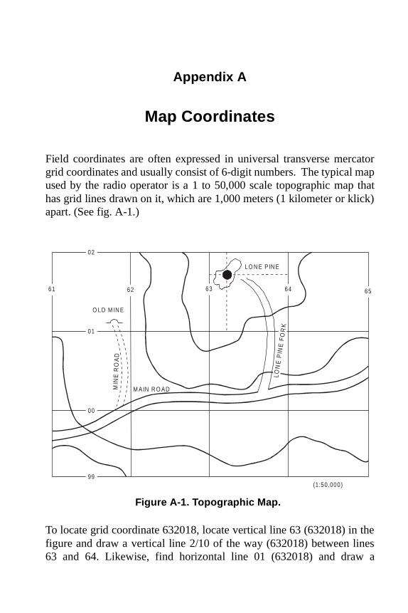
catormap that
ick)
thenes a
Appa.fm Page 1 Friday, June 25, 1999 10:59 AM
Appendix A
Map Coordinates
Field coordinates are often expressed in universal transverse mergrid coordinates and usually consist of 6-digit numbers. The typical used by the radio operator is a 1 to 50,000 scale topographic maphas grid lines drawn on it, which are 1,000 meters (1 kilometer or klapart. (See fig. A-1.)
To locate grid coordinate 632018, locate vertical line 63 (632018) infigure and draw a vertical line 2/10 of the way (632018) between li63 and 64. Likewise, find horizontal line 01 (632018) and draw
LO N E PIN E
O LD M IN E
MIN
E R
OA
D
M A IN R O AD
LON
E P
INE
FO
RK
61
02
01
00
99
62 63 64 65
(1:50,000)
Figure A-1. Topographic Map.

A-2 _______________________________________________ MCRP 6-22C
two
inld be
ld andreas
und The the
Appa.fm Page 2 Friday, June 25, 1999 10:59 AM
horizontal line 8/10 of the way (632018) between it and line 02. Thedrawn lines intersect at Lone Pine.
Similarly, the intersection of the Lone Pine Fork with the Main Roadthe figure would be represented as 638004, and the Old Mine wou618012.
Although the use of the 6-digit number is generally sufficient for fieuse, a more exact coordinate will identify the 100,000 meter squarethe grid zone designation to avoid confusion between different awith identical grid line numbers.
A more detailed explanation of the complete coordinate may be focentered at the bottom of a 1 to 50,000 scale topographic map. order in which the grids are read can be remembered by usingexpression read-right-up.
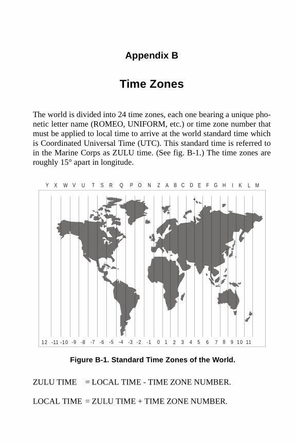
pho-hathichd to are
Appb.fm Page 1 Friday, June 25, 1999 10:58 AM
Appendix B
Time Zones
The world is divided into 24 time zones, each one bearing a unique netic letter name (ROMEO, UNIFORM, etc.) or time zone number tmust be applied to local time to arrive at the world standard time wis Coordinated Universal Time (UTC). This standard time is referrein the Marine Corps as ZULU time. (See fig. B-1.) The time zonesroughly 15° apart in longitude.
ZULU TIME = LOCAL TIME - TIME ZONE NUMBER.
LOCAL TIME = ZULU TIME + TIME ZONE NUMBER.
Z A N BO CP DQ ER FS GT HU IV KW LX MY
0 1 2 3 4 5 6 7 8 9 10 11-11 -10 -9 -8 -7 -6 -5 -4 -3 -2 -112
Figure B-1. Standard Time Zones of the World.
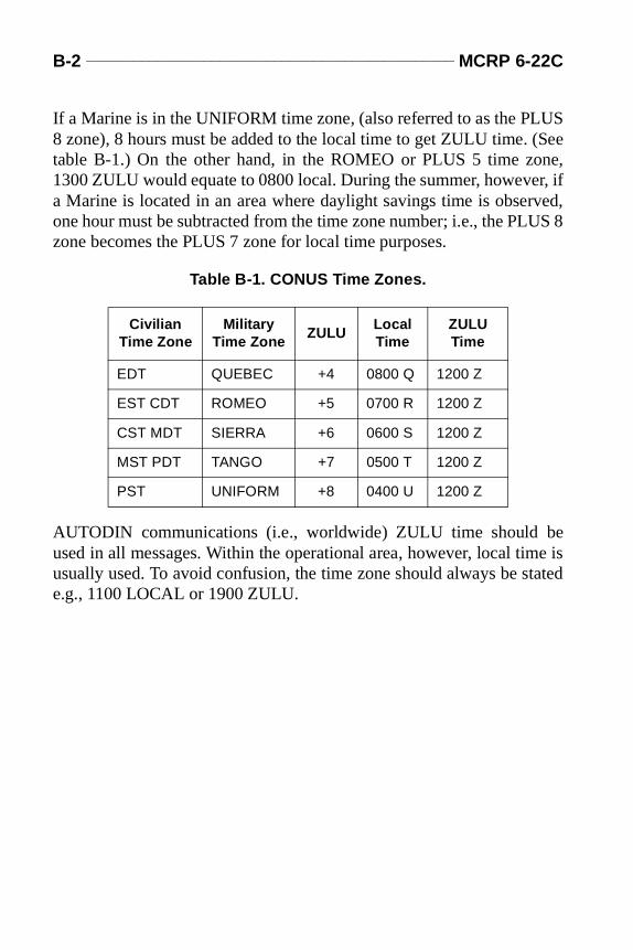
B-2 _______________________________________________ MCRP 6-22C
US(Seene,r, if
rved,US 8
ee is
tated
Appb.fm Page 2 Friday, June 25, 1999 10:58 AM
If a Marine is in the UNIFORM time zone, (also referred to as the PL8 zone), 8 hours must be added to the local time to get ZULU time. table B-1.) On the other hand, in the ROMEO or PLUS 5 time zo1300 ZULU would equate to 0800 local. During the summer, howevea Marine is located in an area where daylight savings time is obseone hour must be subtracted from the time zone number; i.e., the PLzone becomes the PLUS 7 zone for local time purposes.
AUTODIN communications (i.e., worldwide) ZULU time should bused in all messages. Within the operational area, however, local timusually used. To avoid confusion, the time zone should always be se.g., 1100 LOCAL or 1900 ZULU.
Table B-1. CONUS Time Zones.
CivilianTime Zone
Militar yTime Zone
ZULULocalTime
ZULUTime
EDT QUEBEC +4 0800 Q 1200 Z
EST CDT ROMEO +5 0700 R 1200 Z
CST MDT SIERRA +6 0600 S 1200 Z
MST PDT TANGO +7 0500 T 1200 Z
PST UNIFORM +8 0400 U 1200 Z
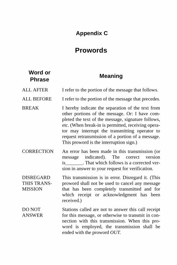
es
-s,-
e.
orn-
ger
n
pt-
-e
Appendix C
Prowords
Word orPhrase
Meaning
ALL AFTER I refer to the portion of the message that follows.
ALL BEFORE I refer to the portion of the message that preced.
BREAK I hereby indicate the separation of the text fromother portions of the message. Or: I have completed the text of the message, signature followetc. (When break-in is permitted, receiving operator may interrupt the transmitting operator torequest retransmission of a portion of a messagThis proword is the interruption sign.)
CORRECTION An error has been made in this transmission (message indicated). The correct versiois_______. That which follows is a corrected version in answer to your request for verification.
DISREGARD THIS TRANS-MISSION
This transmission is in error. Disregard it. (Thisproword shall not be used to cancel any messathat has been completely transmitted and fowhich receipt or acknowledgment has beereceived.)
DO NOT ANSWER
Stations called are not to answer this call receifor this message, or otherwise to transmit in connection with this transmission. When this proword is employed, the transmission shall bended with the proword OUT.
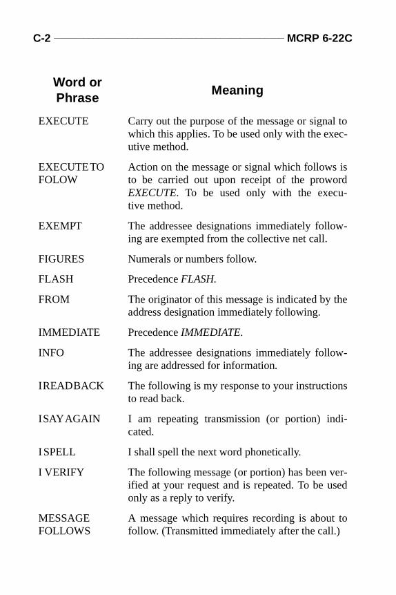
C-2 _______________________________________________ MCRP 6-22C
to-
s
-
e
-
s
i-
r-ed
to
EXECUTE Carry out the purpose of the message or signalwhich this applies. To be used only with the executive method.
EXECUTE TO FOLOW
Action on the message or signal which follows ito be carried out upon receipt of the prowordEXECUTE. To be used only with the execu-tive method.
EXEMPT The addressee designations immediately following are exempted from the collective net call.
FIGURES Numerals or numbers follow.
FLASH Precedence FLASH.
FROM The originator of this message is indicated by thaddress designation immediately following.
IMMEDIATE Precedence IMMEDIATE.
INFO The addressee designations immediately following are addressed for information.
I READ BACK The following is my response to your instructionto read back.
I SAY AGAIN I am repeating transmission (or portion) indcated.
I SPELL I shall spell the next word phonetically.
I VERIFY The following message (or portion) has been veified at your request and is repeated. To be usonly as a reply to verify.
MESSAGE FOLLOWS
A message which requires recording is about follow. (Transmitted immediately after the call.)
Word orPhrase
Meaning

Radio Operator’s Handbook ______________________________ C-3
a
tly
he
o-
y
e
lri-
ed
ens
NUMBER Station serial number.
OUT This is the end of my transmission to you. Noresponse is necessary.
OVER This is the end of my transmission to you and response is necessary. Go ahead and transmit.
PRIORITY Precedence PRIORITY.
READ BACK Repeat this entire transmission back to me exacas received.
RELAY TO Transmit this message to all addressees or to taddress designations immediately following.
ROGER I have received your last transmission satisfactrily.
ROUTINE Precedence ROUTINE.
SAY AGAIN Repeat all of your last transmission. Followed bidentification data means: “Say again (portionindicated).” (“Repeat” is not used because it is thsignal for naval gunfire and artillery to fire.)
SIGNALS FOLLOW
The groups which follow are taken from signabook. (This proword need not be used on nets pmarily employed for conveying signals. It isintended for use when tactical signals are passon nontactical nets.)
SILENCE, SILENCE, SILENCE
Cease transmission immediately. (Silence will bmaintained until instructed to resume. When aauthentication system is in force, transmissionimposing silence are to be authenticated.)
Word orPhrase
Meaning
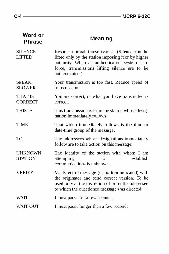
C-4 _______________________________________________ MCRP 6-22C
e
n
of
is
g-
ely
ee
SILENCE LIFTED
Resume normal transmissions. (Silence can blifted only by the station imposing it or by higherauthority. When an authentication system is iforce, transmissions lifting silence are to beauthenticated.)
SPEAK SLOWER
Your transmission is too fast. Reduce speed transmission.
THAT IS CORRECT
You are correct, or what you have transmitted correct.
THIS IS This transmission is from the station whose desination immediately follows.
TIME That which immediately follows is the time ordate-time group of the message.
TO The addressees whose designations immediatfollow are to take action on this message.
UNKNOWN STATION
The identity of the station with whom I amattempting to establishcommunications is unknown.
VERIFY Verify entire message (or portion indicated) withthe originator and send correct version. To bused only at the discretion of or by the addresseto which the questioned message was directed.
WAIT I must pause for a few seconds.
WAIT OUT I must pause longer than a few seconds.
Word orPhrase
Meaning
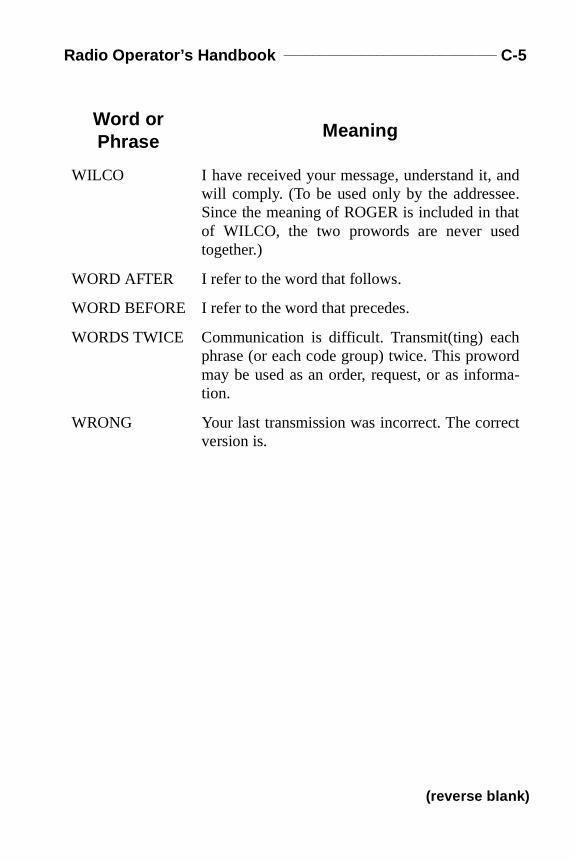
Radio Operator’s Handbook ______________________________ C-5
nd.t
da-
ct
WILCO I have received your message, understand it, awill comply. (To be used only by the addresseeSince the meaning of ROGER is included in thaof WILCO, the two prowords are never usedtogether.)
WORD AFTER I refer to the word that follows.
WORD BEFORE I refer to the word that precedes.
WORDS TWICE Communication is difficult. Transmit(ting) eachphrase (or each code group) twice. This prowormay be used as an order, request, or as informtion.
WRONG Your last transmission was incorrect. The correversion is.
Word orPhrase
Meaning
(reverse blank)

APPD.FM Page 1 Friday, June 25, 1999 10:46 AM
Appendix D
Phonetic Alphabet
Letter Word Pronunciation
A ALFA AL FAH
B BRAVO BRAH VOH
C CHARLIE CHAR LEE
D DELTA DELL TAH
E ECHO ECK OH
F FOXTROT FOKS TROT
G GOLF GOLF
H HOTEL HOH TELL
I INDIA IN DEE AH
J JULIETT JEW LEE ETT
K KILO KEY LOH
L LIMA LEE MAH
M MIKE MIKE
N NOVEMBER NOVEMBER
O OSCAR OSS CAH
P PAPA PAH PAH
Q QUEBEC KEH BECK
R ROMEO ROW ME OH
S SIERRA SEE AIR RAH
T TANGO TANG GO
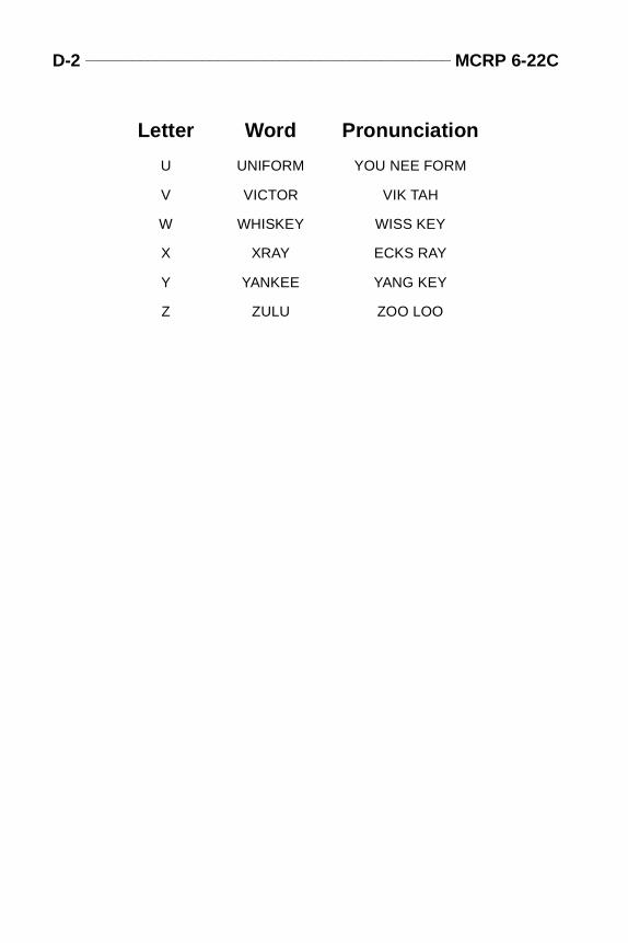
D-2 _______________________________________________ MCRP 6-22C
APPD.FM Page 2 Friday, June 25, 1999 10:46 AM
U UNIFORM YOU NEE FORM
V VICTOR VIK TAH
W WHISKEY WISS KEY
X XRAY ECKS RAY
Y YANKEE YANG KEY
Z ZULU ZOO LOO
Letter Word Pronunciation
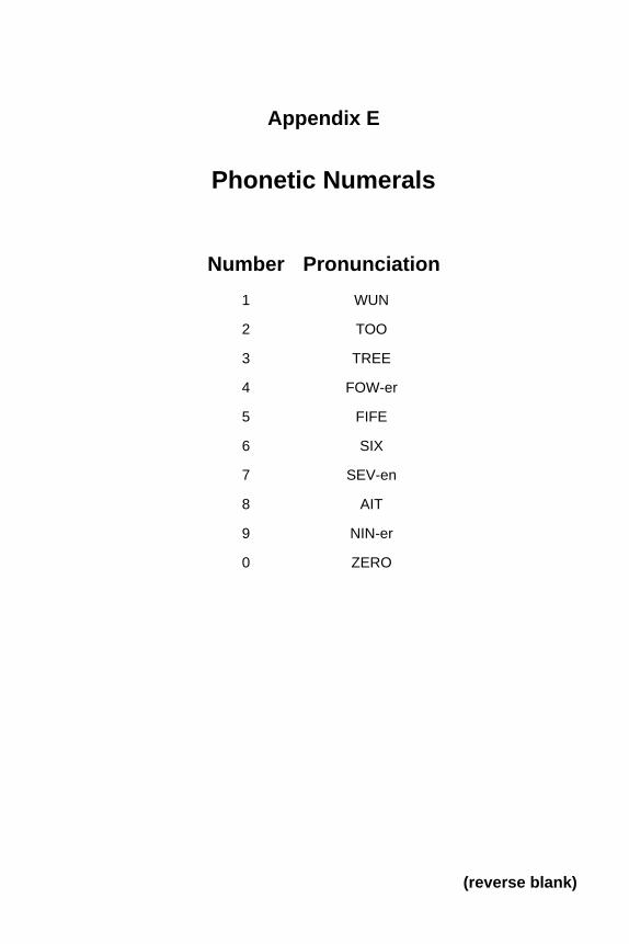
Appendix E
Phonetic Numerals
Number Pronunciation
1 WUN
2 TOO
3 TREE
4 FOW-er
5 FIFE
6 SIX
7 SEV-en
8 AIT
9 NIN-er
0 ZERO
(reverse blank)
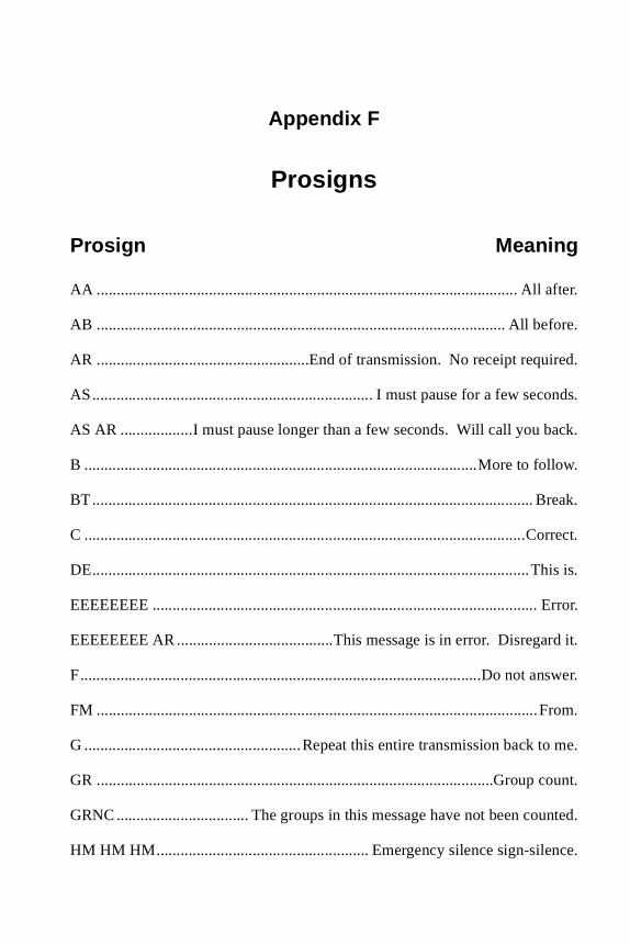
fter.
fore.
ired.
onds.
ack.
llow.
reak.
rrect.
is is.
rror.
rd it.
swer.
rom.
o me.
ount.
unted.
nce.
Appf.fm Page 1 Friday, June 25, 1999 10:47 AM
Appendix F
Prosigns
Prosign Meaning
AA ......................................................................................................... All a
AB ...................................................................................................... All be
AR .....................................................End of transmission. No receipt requ
AS...................................................................... I must pause for a few sec
AS AR ..................I must pause longer than a few seconds. Will call you b
B ..................................................................................................More to fo
BT.............................................................................................................. B
C ..............................................................................................................Co
DE.............................................................................................................Th
EEEEEEEE ................................................................................................ E
EEEEEEEE AR.......................................This message is in error. Disrega
F....................................................................................................Do not an
FM ..............................................................................................................F
G ......................................................Repeat this entire transmission back t
GR ...................................................................................................Group c
GRNC................................. The groups in this message have not been co
HM HM HM..................................................... Emergency silence sign-sile
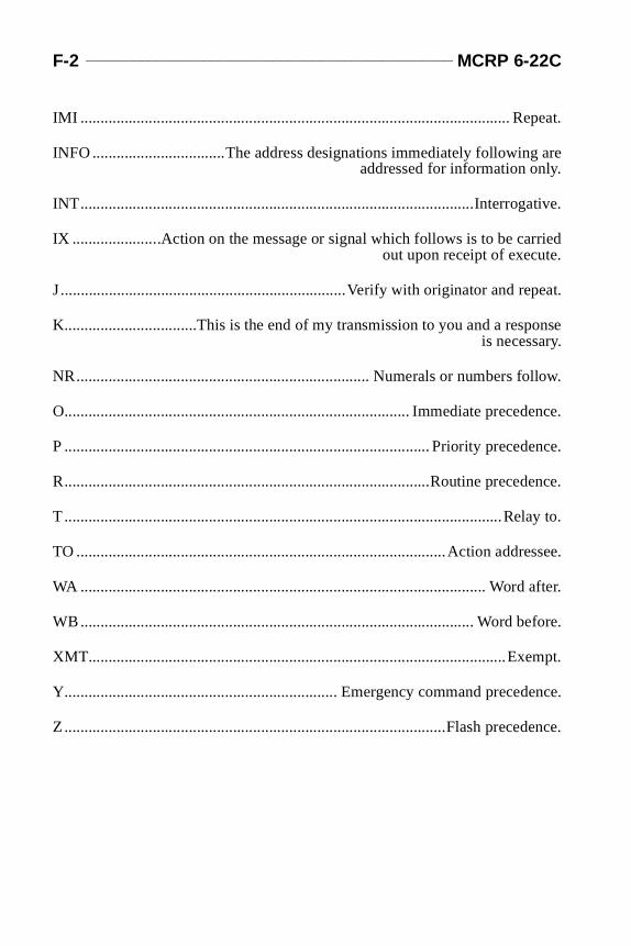
F-2 _______________________________________________ MCRP 6-22C
peat.
are
tive.
ried.
eat.
onse
llow.
ence.
ence.
ence.
ay to.
ssee.
fter.
fore.
mpt.
ence.
ence.
Appf.fm Page 2 Friday, June 25, 1999 10:47 AM
IMI ........................................................................................................... Re
INFO .................................The address designations immediately followingaddressed for information only.
INT..................................................................................................Interroga
IX ......................Action on the message or signal which follows is to be carout upon receipt of execute
J.......................................................................Verify with originator and rep
K.................................This is the end of my transmission to you and a respis necessary.
NR......................................................................... Numerals or numbers fo
O...................................................................................... Immediate preced
P ........................................................................................... Priority preced
R...........................................................................................Routine preced
T.............................................................................................................Rel
TO ............................................................................................Action addre
WA ..................................................................................................... Word a
WB.................................................................................................. Word be
XMT........................................................................................................Exe
Y.................................................................... Emergency command preced
Z...............................................................................................Flash preced
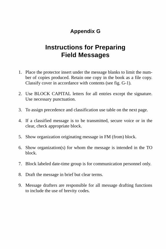
num-opy.
re.
ge.
the
TO
nly.
tions
Appg.fm Page 1 Friday, June 25, 1999 10:58 AM
Appendix G
Instructions for PreparingField Messages
1. Place the protector insert under the message blanks to limit the ber of copies produced. Retain one copy in the book as a file cClassify cover in accordance with contents (see fig. G-1).
2. Use BLOCK CAPITAL letters for all entries except the signatuUse necessary punctuation.
3. To assign precedence and classification use table on the next pa
4. If a classified message is to be transmitted, secure voice or inclear, check appropriate block.
5. Show organization originating message in FM (from) block.
6. Show organization(s) for whom the message is intended in theblock.
7. Block labeled date-time group is for communication personnel o
8. Draft the message in brief but clear terms.
9. Message drafters are responsible for all message drafting functo include the use of brevity codes.
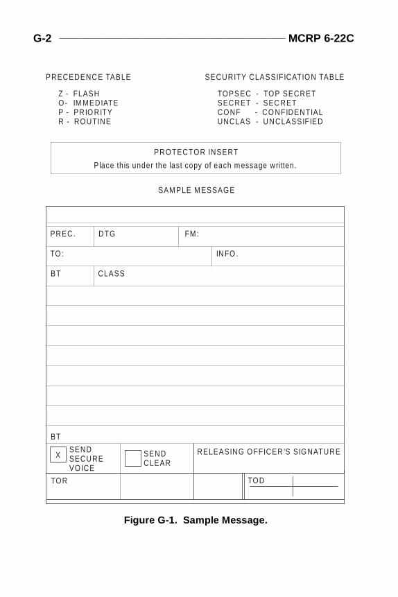
G-2 ______________________________________________ MCRP 6-22C
Appg.fm Page 2 Friday, June 25, 1999 10:58 AM
PRECEDENC E TABLE SECURITY CLASSIFICATION TABLE
Z - FLASH TOPS EC - TOP SECRETO- SECRET - SEC RET IM MEDIATEP - PRIO RITY CONF - CO NFIDENTIALR - ROUTINE UNCLAS - U NCLASSIFIED
PROTECTOR INSERT
Place this under the last copy of each message written.
SAMPLE MESSAGE
PREC.
TO:
BT
BT
TODTOR
SENDSECUREVOICE
SENDCLEAR
RELEASING OFFICER’S SIGNATURE
CLASS
IN FO .
DTG FM:
X
Figure G-1. Sample Message.
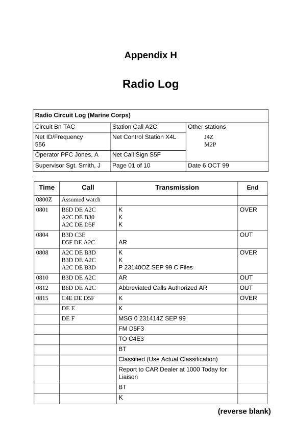
Appendix H
Radio Lo g
(
Radio Circuit Log (Marine Corps)
Circuit Bn TAC Station Call A2C Other stations
Net ID/Frequency556
Net Control Station X4L J4ZM2P
Operator PFC Jones, A Net Call Sign S5F
Supervisor Sgt. Smith, J Page 01 of 10 Date 6 OCT 99
Time Call Transmission End
0800Z Assumed watch
0801 B6D DE A2CA2C DE B30A2C DE D5F
KKK
OVER
0804 B3D C3ED5F DE A2C AR
OUT
0808 A2C DE B3DB3D DE A2CA2C DE B3D
KKP 23140OZ SEP 99 C Files
OVER
0810 B3D DE A2C AR OUT
0812 B6D DE A2C Abbreviated Calls Authorized AR OUT
0815 C4E DE D5F K OVER
DE E K
DE F MSG 0 231414Z SEP 99
FM D5F3
TO C4E3
BT
Classified (Use Actual Classification)
Report to CAR Dealer at 1000 Today for Liaison
BT
K
(reverse blank)
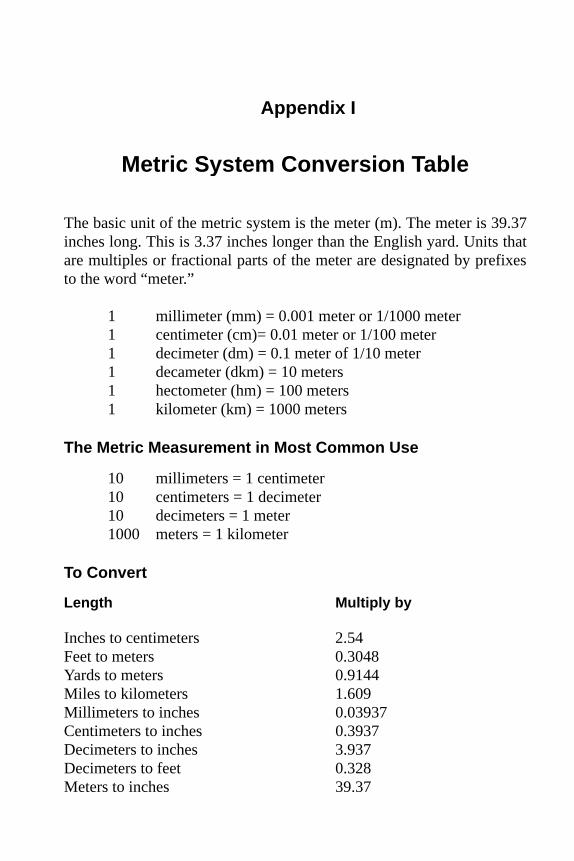
Appendix I
Metric S ystem Conversion Table
The basic unit of the metric system is the meter (m). The meter is 39.37inches long. This is 3.37 inches longer than the English yard. Units thatare multiples or fractional parts of the meter are designated by prefixesto the word “meter.”
1 millimeter (mm) = 0.001 meter or 1/1000 meter1 centimeter (cm)= 0.01 meter or 1/100 meter 1 decimeter (dm) = 0.1 meter of 1/10 meter1 decameter (dkm) = 10 meters1 hectometer (hm) = 100 meters1 kilometer (km) = 1000 meters
The Metric Measurement in Most Common Use
10 millimeters = 1 centimeter10 centimeters = 1 decimeter10 decimeters = 1 meter1000 meters = 1 kilometer
To Convert
Length Multiply by
Inches to centimeters 2.54Feet to meters 0.3048Yards to meters 0.9144Miles to kilometers 1.609Millimeters to inches 0.03937Centimeters to inches 0.3937Decimeters to inches 3.937Decimeters to feet 0.328Meters to inches 39.37

I-2 ________________________________________________ MCRP 6-22C
Meters to feet 3.28Meters to yards 1.0936Decameters to feet 32.8Hectometers to feet 328.1Kilometers to feet 3281Kilometers to yards 1093.6Kilometers to miles 0.62
Examples:
To change 90 kilometers to miles: 90 x .62 = 55.8 milesTo change 90 kilometers to feet: 90 x 3281 = 295,290 feetTo change 50 yards to meters: 50 x 0.9144 = 45.72 meters
Appendix J
Authentication
Authentication systems are provided to prevent unauthorized enemy sta-tions from entering friendly radio nets to disrupt or confuse operations.The only authentication systems authorized are those approved for useby the National Security Agency. If a special or emergency requirementarises, notify the CIS officer (G-6/S-6).
INSTRUCTIONS
There are two methods of authentication that are authorized for use:challenge and reply authentication and transmission authentication. Theoperational distinction is that challenge and reply requires two-waycommunications, whereas transmission authentication does not.
Challenge and Reply Authentication
Challenge and reply authentication will be used whenever possible. Thecalled party will always make the first challenge. Besides validating theauthenticity of the calling station, this practice prevents an enemy opera-tor from entering a net to obtain correct authentication responses for usein another net. The party making the call may counterchallenge thecalled party using a different challenge.
Note: In challenge and reply authentication, only the station respond-ing is verified. Do not accept a challenge as an authentication.
When a caller desires authentication, he must invite a challenge by stat-ing that he is prepared to authenticate.
Another challenge should be made if an incorrect reply is received, if astandby is requested, or if an unusual delay occurs between challengeand reply.
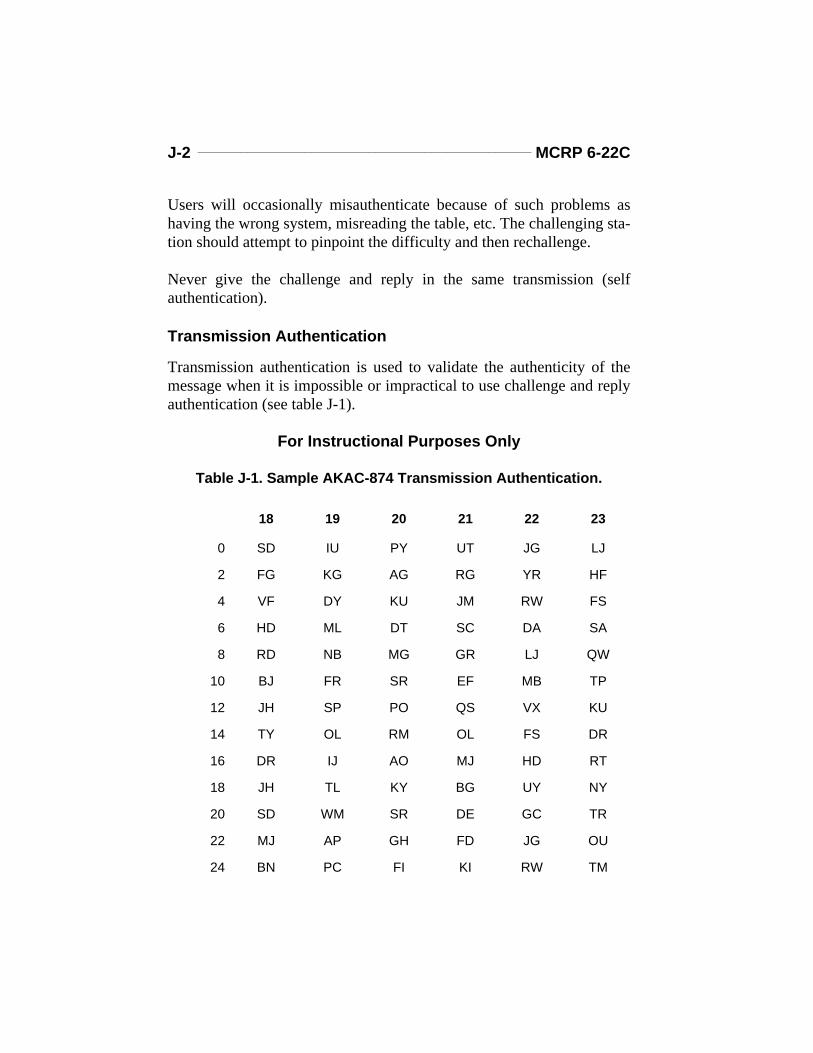
J-2 _______________________________________________ MCRP 6-22C
Users will occasionally misauthenticate because of such problems ashaving the wrong system, misreading the table, etc. The challenging sta-tion should attempt to pinpoint the difficulty and then rechallenge.
Never give the challenge and reply in the same transmission (selfauthentication).
Transmission Authentication
Transmission authentication is used to validate the authenticity of themessage when it is impossible or impractical to use challenge and replyauthentication (see table J-1).
For Instructional Purposes Only
Table J-1. Sample AKAC-874 Transmission Authentication.
18 19 20 21 22 23
0 SD IU PY UT JG LJ
2 FG KG AG RG YR HF
4 VF DY KU JM RW FS
6 HD ML DT SC DA SA
8 RD NB MG GR LJ QW
10 BJ FR SR EF MB TP
12 JH SP PO QS VX KU
14 TY OL RM OL FS DR
16 DR IJ AO MJ HD RT
18 JH TL KY BG UY NY
20 SD WM SR DE GC TR
22 MJ AP GH FD JG OU
24 BN PC FI KI RW TM
Radio Operator’s Handbook ______________________________ J-3
WHEN TO AUTHENTICATE
Transmission should be authenticated—
l When any station suspects imitative deception on any circuit; e.g.,when contacting a station following one or more unsuccessfulattempts to contact that station.
l When any station is challenged or requested to authenticate. This isnot to be interpreted as requiring stations to break an imposed silencefor the sole purpose of authenticating.
l When directing radio silence, listening silence, or requiring a stationto break an imposed silence.
l When transmitting contact and amplifying reports in plain language.l When transmitting operating instructions that affect the military situ-
ation; e.g., closing down a station or watch, changing frequency otherthan normal scheduled changes, directing establishment of a specialcommunication guard, requesting artillery fire support, directing relo-cation of units, etc.
l When transmitting a plain language cancellation.l When making initial radio contact or resuming contact after pro-
longed interruptions.l When transmitting to a station that is under radio listening silence. l When authorized to transmit a classified message in the clear.l When forced, because of no response by the called station to send a
message in the blind (transmission authentication).
Note: Authentication is not required when making initial contact aftera scheduled call sign and frequency change since only bona fide sta-tions will know their assigned call sign and frequency for the timeperiod in use.
For detailed authentication instructions refer to the automated communi-cations-electronics operations instructions.
(reverse blank)
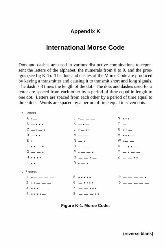
Appendix K
International Morse Code
Dots and dashes are used in various distinctive combinations to repre-sent the letters of the alphabet, the numerals from 0 to 9, and the pros-igns (see fig K-1). The dots and dashes of the Morse Code are producedby keying a transmitter and causing it to transmit short and long signals.The dash is 3 times the length of the dot. The dots and dashes used for aletter are spaced from each other by a period of time equal in length toone dot. Letters are spaced from each other by a period of time equal tothree dots. Words are spaced by a period of time equal to seven dots.
a. Letters
b. F igures
A J S
E N W
F O X
G P Y
H Q Z
I R
B K T
C L U
D M V
1 5 9
2 6 0
3 7
4 8
Figure K-1. Morse Code.
(reverse blank)
Appk.fm Page 1 Friday, June 25, 1999 10:58 AM
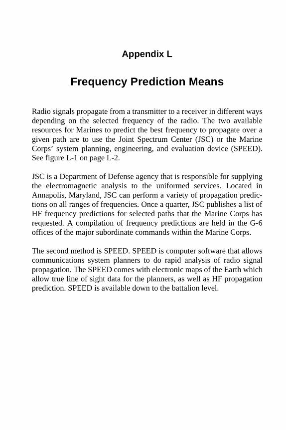
ayslablever aarineED).
lyingd indic-list of hasG-6.
llowsgnalhichtion
Appl.fm Page 1 Friday, June 25, 1999 10:57 AM
Appendix L
Frequency Prediction Means
Radio signals propagate from a transmitter to a receiver in different wdepending on the selected frequency of the radio. The two avairesources for Marines to predict the best frequency to propagate ogiven path are to use the Joint Spectrum Center (JSC) or the MCorps’ system planning, engineering, and evaluation device (SPESee figure L-1 on page L-2.
JSC is a Department of Defense agency that is responsible for suppthe electromagnetic analysis to the uniformed services. LocateAnnapolis, Maryland, JSC can perform a variety of propagation pretions on all ranges of frequencies. Once a quarter, JSC publishes a HF frequency predictions for selected paths that the Marine Corpsrequested. A compilation of frequency predictions are held in the offices of the major subordinate commands within the Marine Corps
The second method is SPEED. SPEED is computer software that acommunications system planners to do rapid analysis of radio sipropagation. The SPEED comes with electronic maps of the Earth wallow true line of sight data for the planners, as well as HF propagaprediction. SPEED is available down to the battalion level.
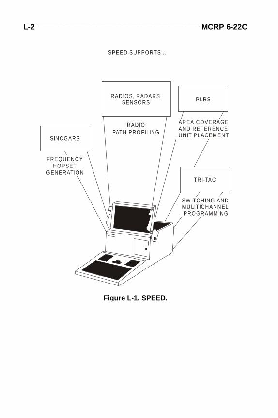
L-2 _______________________________________________ MCRP 6-22C
Appl.fm Page 2 Friday, June 25, 1999 10:57 AM
RADIOS, RADARS, SENSORS PLRS
SIN CGARS
RADIOPATH PROFILING
SPE ED SUPPORTS...
AREA COVERAGE AND REFERENCE UNIT PLACEMEN T
FREQUENC Y HOPSETGENERATION
TRI-TAC
SW ITCHING AND MU LITICHANN EL PROGRAMM ING
Figure L-1. SPEED.
temerate.
ignedion,ellite),(GPSls on
trans-eing
ighlytionPS
n as
, andbasicfor-id- the usern be
thenatic47- 300- by
Appm.fm Page 1 Friday, June 25, 1999 10:57 AM
Appendix M
Position and Navigation Systems
Global positioning system (GPS) and position location reporting sys(PLRS) are new systems that radio operators may be required to op
GLOBAL POSITIONING SYSTEM
Global positioning system is a space-based navigation system desto provide 24-hour continuous worldwide, all-weather precise positand time measurement. The GPS consists of a space segment (satcontrol segment (monitors stations on Earth), and user segment receivers). The system operates by satellites sending out two signanonchanging frequencies. The GPS receiver receives the signals mitted by the satellites and computes the users position. GPS (by ban all-weather, jam-resistant, continuous system) gives users haccurate navigation; worldwide, three-dimensional position or locavelocity; and time information. As a passive, receive-only system, Gcan be employed at the individual level in such nondescript terraijungles, mountain ranges, or deserts. (See fig. M-1 on page M-2.)
POSITION LOCATION REPORTING SYSTEM
PLRS is a system of UHF radios, signal and message processorsuser input and output devices configured as master stations and units that provide the user of the system with position navigation inmation and limited digital communications. PLRS works by the indivual units in the network time sharing a single frequency band. Asmaster station records the arrival time of the signal bursts from eachunit at given locations, the range between sender and receiver cacomputed. If units are beyond line of sight for the master station, PLRS will automatically enable any user unit to serve as an automrelay. The full PLRS performance can be provided over a 47- by kilometer operating area. This operating area can be extended to aby 300-kilometer area through the use of airborne relays providedPLRS-equipped aircraft.
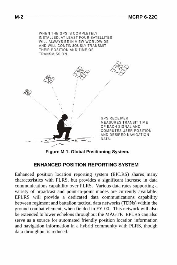
M-2 ______________________________________________ MCRP 6-22C
anydatang able.ility thelso alsotiongh
Appm.fm Page 2 Friday, June 25, 1999 10:57 AM
ENHANCED POSITION REPORTING SYSTEM
Enhanced position location reporting system (EPLRS) shares mcharacteristics with PLRS, but provides a significant increase in communications capability over PLRS. Various data rates supportivariety of broadcast and point-to-point modes are currently availaEPLRS will provide a dedicated data communications capabbetween regiment and battalion tactical data networks (TDNs) withinground combat element, when fielded in FY-00. This network will abe extended to lower echelons throughout the MAGTF. EPLRS canserve as a source for automated friendly position location informaand navigation information in a hybrid community with PLRS, thoudata throughput is reduced.
W H EN THE GPS IS COM PLETELYIN STALLE D, AT LEAST FO UR SATELLITE SW ILL ALWAYS BE IN VIEW W ORLDW IDEAND W ILL CONTIN UOUSLY TR ANSMITTHEIR POSITION AND TIME OFTRANSMISSIO N.
GPS RECEIVERMEASUR ES TRANSIT TIM EOF EACH SIGNAL ANDCOM PUTES USER POSITIONAND DESIRED NAVIGATIONDATA .
Figure M-1. Global Positioning System.
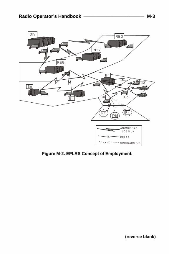
Radio Operator’s Handbook _____________________________ M-3
Appm.fm Page 3 Friday, June 25, 1999 10:57 AM
REG
REG
REG
Bn
Bn Co Co
Co
A N /M R C -1 4 2 L O S M U X
E P L R S
S IN C G A R S S IP
PltP lt
P lt
D IV
Bn
Figure M-2. EPLRS Concept of Employment.
(reverse blank)
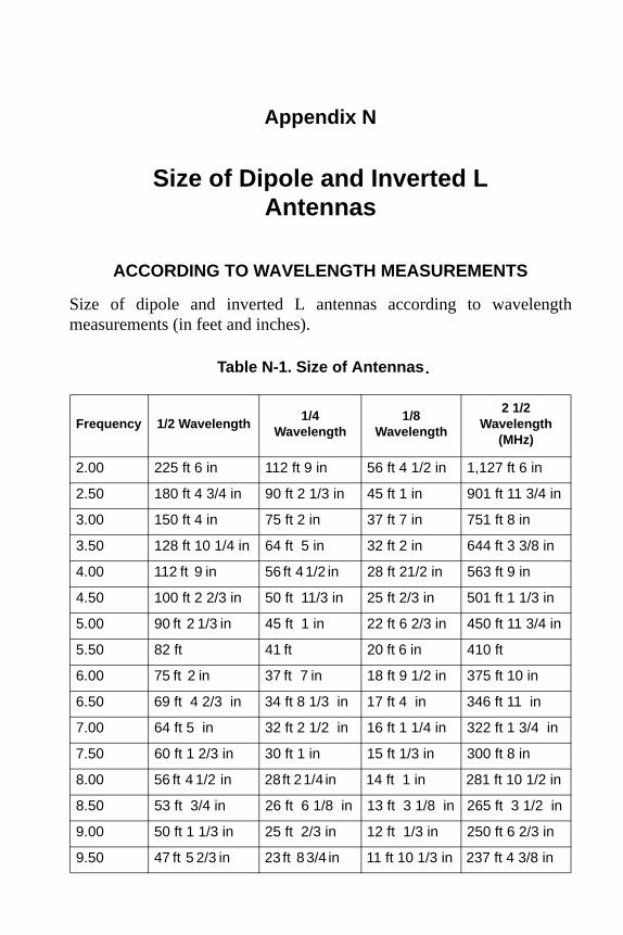
Appendix N
Size of Di pole and Inverted LAntennas
ACCORDING TO WAVELENGTH MEASUREMENTS
Size of dipole and inverted L antennas according to wavelengthmeasurements (in feet and inches).
Table N-1. Size of Antennas
Frequency 1/2 Wavelength1/4
Wavelength1/8
Wavelength
2 1/2 Wavelength
(MHz)
2.00 225 ft 6 in 112 ft 9 in 56 ft 4 1/2 in 1,127 ft 6 in
2.50 180 ft 4 3/4 in 90 ft 2 1/3 in 45 ft 1 in 901 ft 11 3/4 in
3.00 150 ft 4 in 75 ft 2 in 37 ft 7 in 751 ft 8 in
3.50 128 ft 10 1/4 in 64 ft 5 in 32 ft 2 in 644 ft 3 3/8 in
4.00 112 ft 9 in 56 ft 4 1/2 in 28 ft 21/2 in 563 ft 9 in
4.50 100 ft 2 2/3 in 50 ft 11/3 in 25 ft 2/3 in 501 ft 1 1/3 in
5.00 90 ft 2 1/3 in 45 ft 1 in 22 ft 6 2/3 in 450 ft 11 3/4 in
5.50 82 ft 41 ft 20 ft 6 in 410 ft
6.00 75 ft 2 in 37 ft 7 in 18 ft 9 1/2 in 375 ft 10 in
6.50 69 ft 4 2/3 in 34 ft 8 1/3 in 17 ft 4 in 346 ft 11 in
7.00 64 ft 5 in 32 ft 2 1/2 in 16 ft 1 1/4 in 322 ft 1 3/4 in
7.50 60 ft 1 2/3 in 30 ft 1 in 15 ft 1/3 in 300 ft 8 in
8.00 56 ft 4 1/2 in 28 ft 2 1/4 in 14 ft 1 in 281 ft 10 1/2 in
8.50 53 ft 3/4 in 26 ft 6 1/8 in 13 ft 3 1/8 in 265 ft 3 1/2 in
9.00 50 ft 1 1/3 in 25 ft 2/3 in 12 ft 1/3 in 250 ft 6 2/3 in
9.50 47 ft 5 2/3 in 23 ft 8 3/4 in 11 ft 10 1/3 in 237 ft 4 3/8 in
.
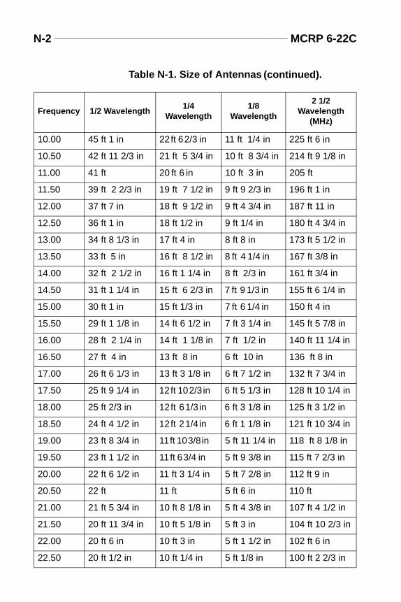
N-2 _______________________________________________ MCRP 6-22C
10.00 45 ft 1 in 22 ft 6 2/3 in 11 ft 1/4 in 225 ft 6 in
10.50 42 ft 11 2/3 in 21 ft 5 3/4 in 10 ft 8 3/4 in 214 ft 9 1/8 in
11.00 41 ft 20 ft 6 in 10 ft 3 in 205 ft
11.50 39 ft 2 2/3 in 19 ft 7 1/2 in 9 ft 9 2/3 in 196 ft 1 in
12.00 37 ft 7 in 18 ft 9 1/2 in 9 ft 4 3/4 in 187 ft 11 in
12.50 36 ft 1 in 18 ft 1/2 in 9 ft 1/4 in 180 ft 4 3/4 in
13.00 34 ft 8 1/3 in 17 ft 4 in 8 ft 8 in 173 ft 5 1/2 in
13.50 33 ft 5 in 16 ft 8 1/2 in 8 ft 4 1/4 in 167 ft 3/8 in
14.00 32 ft 2 1/2 in 16 ft 1 1/4 in 8 ft 2/3 in 161 ft 3/4 in
14.50 31 ft 1 1/4 in 15 ft 6 2/3 in 7 ft 9 1/3 in 155 ft 6 1/4 in
15.00 30 ft 1 in 15 ft 1/3 in 7 ft 6 1/4 in 150 ft 4 in
15.50 29 ft 1 1/8 in 14 ft 6 1/2 in 7 ft 3 1/4 in 145 ft 5 7/8 in
16.00 28 ft 2 1/4 in 14 ft 1 1/8 in 7 ft 1/2 in 140 ft 11 1/4 in
16.50 27 ft 4 in 13 ft 8 in 6 ft 10 in 136 ft 8 in
17.00 26 ft 6 1/3 in 13 ft 3 1/8 in 6 ft 7 1/2 in 132 ft 7 3/4 in
17.50 25 ft 9 1/4 in 12 ft 10 2/3 in 6 ft 5 1/3 in 128 ft 10 1/4 in
18.00 25 ft 2/3 in 12 ft 6 1/3 in 6 ft 3 1/8 in 125 ft 3 1/2 in
18.50 24 ft 4 1/2 in 12 ft 2 1/4 in 6 ft 1 1/8 in 121 ft 10 3/4 in
19.00 23 ft 8 3/4 in 11 ft 10 3/8 in 5 ft 11 1/4 in 118 ft 8 1/8 in
19.50 23 ft 1 1/2 in 11 ft 6 3/4 in 5 ft 9 3/8 in 115 ft 7 2/3 in
20.00 22 ft 6 1/2 in 11 ft 3 1/4 in 5 ft 7 2/8 in 112 ft 9 in
20.50 22 ft 11 ft 5 ft 6 in 110 ft
21.00 21 ft 5 3/4 in 10 ft 8 1/8 in 5 ft 4 3/8 in 107 ft 4 1/2 in
21.50 20 ft 11 3/4 in 10 ft 5 1/8 in 5 ft 3 in 104 ft 10 2/3 in
22.00 20 ft 6 in 10 ft 3 in 5 ft 1 1/2 in 102 ft 6 in
22.50 20 ft 1/2 in 10 ft 1/4 in 5 ft 1/8 in 100 ft 2 2/3 in
Table N-1. Size of Antennas
Frequency 1/2 Wavelength1/4
Wavelength1/8
Wavelength
2 1/2 Wavelength
(MHz)
(continued).
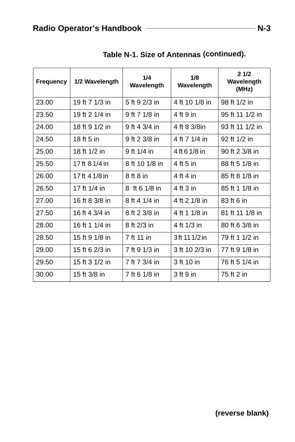
Radio Operator’s Handbook ______________________________ N-3
23.00 19 ft 7 1/3 in 5 ft 9 2/3 in 4 ft 10 1/8 in 98 ft 1/2 in
23.50 19 ft 2 1/4 in 9 ft 7 1/8 in 4 ft 9 in 95 ft 11 1/2 in
24.00 18 ft 9 1/2 in 9 ft 4 3/4 in 4 ft 8 3/8in 93 ft 11 1/2 in
24.50 18 ft 5 in 9 ft 2 3/8 in 4 ft 7 1/4 in 92 ft 1/2 in
25.00 18 ft 1/2 in 9 ft 1/4 in 4 ft 6 1/8 in 90 ft 2 3/8 in
25.50 17 ft 8 1/4 in 8 ft 10 1/8 in 4 ft 5 in 88 ft 5 1/8 in
26.00 17 ft 4 1/8 in 8 ft 8 in 4 ft 4 in 85 ft 8 1/8 in
26.50 17 ft 1/4 in 8 ft 6 1/8 in 4 ft 3 in 85 ft 1 1/8 in
27.00 16 ft 8 3/8 in 8 ft 4 1/4 in 4 ft 2 1/8 in 83 ft 6 in
27.50 16 ft 4 3/4 in 8 ft 2 3/8 in 4 ft 1 1/8 in 81 ft 11 1/8 in
28.00 16 ft 1 1/4 in 8 ft 2/3 in 4 ft 1/3 in 80 ft 6 3/8 in
28.50 15 ft 9 1/8 in 7 ft 11 in 3 ft 11 1/2 in 79 ft 1 1/2 in
29.00 15 ft 6 2/3 in 7 ft 9 1/3 in 3 ft 10 2/3 in 77 ft 9 1/8 in
29.50 15 ft 3 1/2 in 7 ft 7 3/4 in 3 ft 10 in 76 ft 5 1/4 in
30.00 15 ft 3/8 in 7 ft 6 1/8 in 3 ft 9 in 75 ft 2 in
Table N-1. Size of Antennas
Frequency 1/2 Wavelength1/4
Wavelength1/8
Wavelength
2 1/2 Wavelength
(MHz)
(continued).
(reverse blank)
muni-lacestructs ondjust-
theto thee thehipn thedly
ce ofhen,n thenect-
ace-epair
Appo.fm Page 1 Friday, June 25, 1999 11:17 AM
Appendix O
Field Repair and Expedients
Section I. Antenna Repair
Antennas are sometimes broken or damaged, causing either a comcations failure or poor communications. If a spare is available, repthe damaged antenna. When there is no spare, you may have to conan emergency antenna. The following paragraphs are suggestionrepairing antennas and antenna supports and on constructing and aing emergency antennas.
REPAIR TECHNIQUES
Whip Antennas
When a whip antenna is broken into two sections, the portion ofantenna that is broken off can be connected to the portion attached base by joining the sections as shown in figure O-1 on page O-2. Usmethod illustrated in figure O-1A, when both parts of the broken ware available and usable. Use the method shown in figure O-1B wheportion of the whip that was broken off is lost, or when the whip is badamaged. To restore the antenna to its original length, add a piewire that is nearly the same length as the missing part of the whip. Tlash the pole support securely to both sections of the antenna. Cleatwo antenna sections thoroughly to ensure good contact before coning them to the pole support. If possible, solder the connections.
Wire Antennas
Emergency repair of a wire antenna may involve the repair or replment of the wire used as the antenna or transmission line; or, the ror replacement of the assembly used to support the antenna.
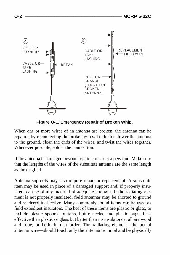
O-2 ______________________________________________ MCRP 6-22C
an beennather.
surelength
tituteinsu- ele-oundd asss, toLessood
tualcally
Appo.fm Page 2 Friday, June 25, 1999 11:17 AM
When one or more wires of an antenna are broken, the antenna crepaired by reconnecting the broken wires. To do this, lower the antto the ground, clean the ends of the wires, and twist the wires togeWhenever possible, solder the connection.
If the antenna is damaged beyond repair, construct a new one. Makethat the lengths of the wires of the substitute antenna are the same as the original.
Antenna supports may also require repair or replacement. A subsitem may be used in place of a damaged support and, if properly lated, can be of any material of adequate strength. If the radiatingment is not properly insulated, field antennas may be shorted to grand rendered ineffective. Many commonly found items can be usefield expedient insulators. The best of these items are plastic or glainclude plastic spoons, buttons, bottle necks, and plastic bags. effective than plastic or glass but better than no insulators at all are wand rope, or both, in that order. The radiating element—the acantenna wire—should touch only the antenna terminal and be physi
POLE O R BRANCH
CABLE O R TAPE LASHING
CABLE O R TAPE LASHING
BREAK
A B
REPLACEMENTFIELD W IRE
POLE O R BRANCH(LENG TH OFBROKENANTENNA)
Figure O-1. Emergency Repair of Broken Whip.
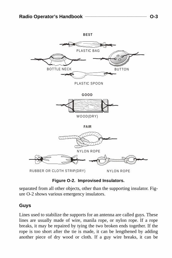
Radio Operator’s Handbook _____________________________ O-3
Fig-
Theseopef theding
be
Appo.fm Page 3 Friday, June 25, 1999 11:17 AM
separated from all other objects, other than the supporting insulator.ure O-2 shows various emergency insulators.
Guys
Lines used to stabilize the supports for an antenna are called guys. lines are usually made of wire, manila rope, or nylon rope. If a rbreaks, it may be repaired by tying the two broken ends together. Irope is too short after the tie is made, it can be lengthened by adanother piece of dry wood or cloth. If a guy wire breaks, it can
PLASTIC SPOON
NYLON ROPE
BUTTON
PLASTIC BAG
BOTTLE NECK
W O OD(DRY)
RUBBER OR CLOTH STRIP(DRY)
NYLON ROPE
BEST
GOO D
FAIR
Figure O-2. Improvised Insulators.
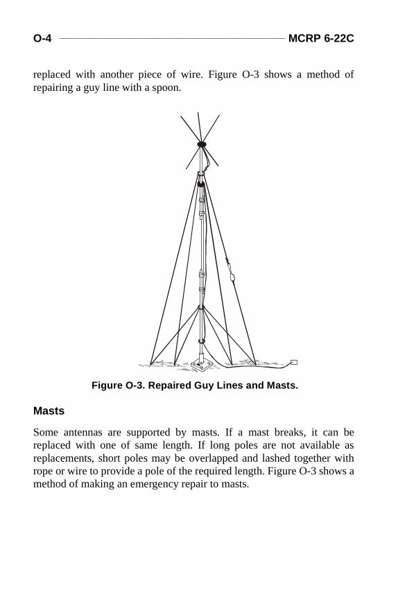
O-4 ______________________________________________ MCRP 6-22C
d of
an be as
r withws a
Appo.fm Page 4 Friday, June 25, 1999 11:17 AM
replaced with another piece of wire. Figure O-3 shows a methorepairing a guy line with a spoon.
Masts
Some antennas are supported by masts. If a mast breaks, it creplaced with one of same length. If long poles are not availablereplacements, short poles may be overlapped and lashed togetherope or wire to provide a pole of the required length. Figure O-3 shomethod of making an emergency repair to masts.
Figure O-3. Repaired Guy Lines and Masts.
Radio Operator’s Handbook _____________________________ O-5
n an
ould
s ifp thetreesother rope keep
nsurena,
sula-
. Userly.
eived thetrans- vol-enna
st, setera-tenna
Appo.fm Page 5 Friday, June 25, 1999 11:17 AM
TIPS FOR CONSTRUCTION AND ADJUSTMENT
Constructing the Antenna
The best kinds of wire for antennas are copper and aluminum. Iemergency, however, use any type that is available.
The length of most antennas is critical. The emergency antenna shbe the same length as the antenna it replaces.
Antennas supported by trees can usually survive heavy wind stormthe trunk of a tree or a strong branch is used as a support. To keeantenna taut and to prevent it from breaking or stretching as the sway, attach a spring or old inner tube to one end of the antenna. Antechnique is to pass a rope through a pulley or eyehook, attach theto the end of the antenna, and load the rope with a heavy weight tothe antenna tightly drawn.
Guys used to hold antenna supports are made of rope or wire. To ethat the guys made of wire will not affect the operation of the antencut the wire into several short lengths and connect the pieces with intors.
Adjusting the Antenna
An improvised antenna may change the performance of a radio setthe following methods to determine if the antenna is operating prope
A distant station may be used to test the antenna. If the signal recfrom this station is strong, the antenna is operating satisfactorily. Ifsignal is weak, adjust the height and length of the antenna and the mission line to receive the strongest signal at a given setting on theume control of the receiver. This is the best method of tuning an antwhen transmission is dangerous or forbidden.
In some radio sets, the transmitter is used to adjust the antenna. Firthe controls of the transmitter in the proper position for normal option; then, tune the system by adjusting the antenna height, the an
O-6 ______________________________________________ MCRP 6-22C
sion
on inart of the buteters,
for-existctlyding- and
Appo.fm Page 6 Friday, June 25, 1999 11:17 AM
length, and the transmission line length to obtain the best transmisoutput.
Impedance-matching a load to its source is an important consideratitransmissions’ systems. If the load and source are mismatched, pthe power is reflected back along the transmission line towardssource. This reflection not only prevents maximum power transfer,can also be responsible for erroneous measurements of other paramor even cause circuit damage in high-power applications.
The power reflected from the load interferes with the incident (i.e., ward) power, causing standing waves of voltages and current to along the line. The ratio of standing-wave maxima to minima is direrelated to the impedance mismatch of the load; therefore the stanwave ratio (SWR) provides the means of determining impedancemismatch.
WARNINGSERIOUS INJURY OR DEATH CAN RESULT FROM CONTACTWITH THE RADIATING ANTENNA OF A MEDIUM- OR HIGH-POW-ER TRANSMITTER. TURN THE TRANSMITTER OFF WHILE MAK-
ING ADJUSTMENTS TO THE ANTENNA.
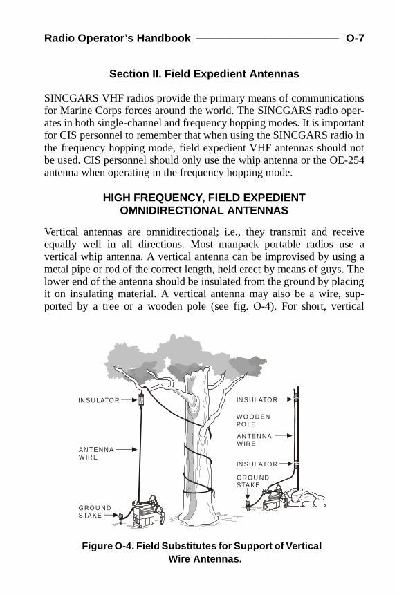
Radio Operator’s Handbook _____________________________ O-7
onser-rtantio in not-254
eivee ang a Thecingup-tical
Appo.fm Page 7 Friday, June 25, 1999 11:17 AM
Section II. Field Expedient Antennas
SINCGARS VHF radios provide the primary means of communicatifor Marine Corps forces around the world. The SINCGARS radio opates in both single-channel and frequency hopping modes. It is impofor CIS personnel to remember that when using the SINCGARS radthe frequency hopping mode, field expedient VHF antennas shouldbe used. CIS personnel should only use the whip antenna or the OEantenna when operating in the frequency hopping mode.
HIGH FREQUENCY, FIELD EXPEDIENT OMNIDIRECTIONAL ANTENNAS
Vertical antennas are omnidirectional; i.e., they transmit and recequally well in all directions. Most manpack portable radios usvertical whip antenna. A vertical antenna can be improvised by usimetal pipe or rod of the correct length, held erect by means of guys.lower end of the antenna should be insulated from the ground by plait on insulating material. A vertical antenna may also be a wire, sported by a tree or a wooden pole (see fig. O-4). For short, ver
IN S ULATO R
G RO U ND STA KE
G RO U NDSTA KE
AN TE NNA W IR E
AN TE NNA W IR E
W O O D EN PO LE
IN S ULATO R
IN S ULATO R
Figure O-4. Field Substitutes for Support of Vertical Wire Antennas.
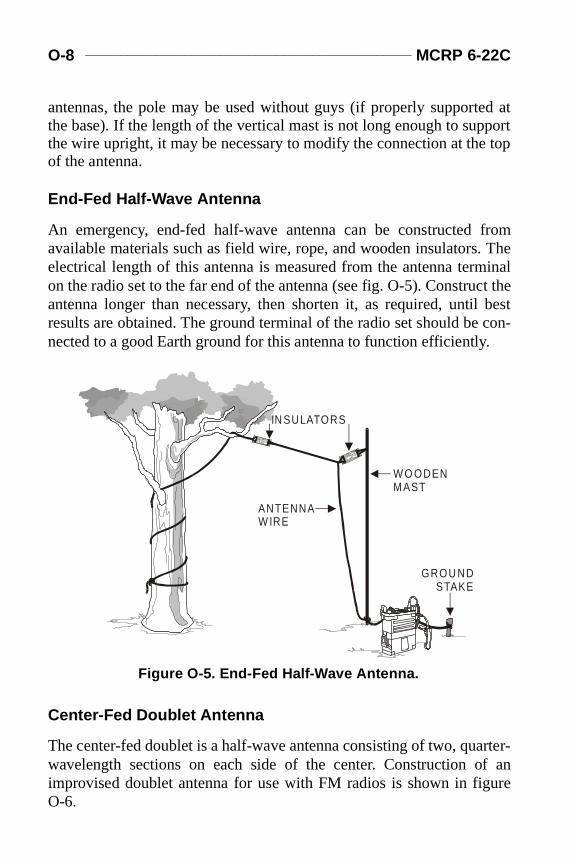
O-8 ______________________________________________ MCRP 6-22C
d atport top
from Theinal
ct thel best con-.
rter-f anure
Appo.fm Page 8 Friday, June 25, 1999 11:17 AM
antennas, the pole may be used without guys (if properly supportethe base). If the length of the vertical mast is not long enough to supthe wire upright, it may be necessary to modify the connection at theof the antenna.
End-Fed Half-Wave Antenna
An emergency, end-fed half-wave antenna can be constructed available materials such as field wire, rope, and wooden insulators.electrical length of this antenna is measured from the antenna termon the radio set to the far end of the antenna (see fig. O-5). Construantenna longer than necessary, then shorten it, as required, untiresults are obtained. The ground terminal of the radio set should benected to a good Earth ground for this antenna to function efficiently
Center-Fed Doublet Antenna
The center-fed doublet is a half-wave antenna consisting of two, quawavelength sections on each side of the center. Construction oimprovised doublet antenna for use with FM radios is shown in figO-6.
IN SULATORS
GROU ND STAKE
ANTENNA W IRE
W O ODEN MAST
Figure O-5. End-Fed Half-Wave Antenna.
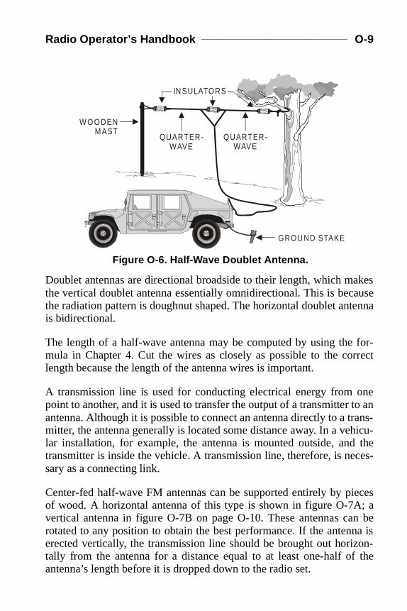
Radio Operator’s Handbook _____________________________ O-9
akesausetenna
for-rrect
oneto anrans-hicu- theces-
ieces; an be
na ison- the
Appo.fm Page 9 Friday, June 25, 1999 11:17 AM
Doublet antennas are directional broadside to their length, which mthe vertical doublet antenna essentially omnidirectional. This is becthe radiation pattern is doughnut shaped. The horizontal doublet anis bidirectional.
The length of a half-wave antenna may be computed by using themula in Chapter 4. Cut the wires as closely as possible to the colength because the length of the antenna wires is important.
A transmission line is used for conducting electrical energy from point to another, and it is used to transfer the output of a transmitter antenna. Although it is possible to connect an antenna directly to a tmitter, the antenna generally is located some distance away. In a velar installation, for example, the antenna is mounted outside, andtransmitter is inside the vehicle. A transmission line, therefore, is nesary as a connecting link.
Center-fed half-wave FM antennas can be supported entirely by pof wood. A horizontal antenna of this type is shown in figure O-7Avertical antenna in figure O-7B on page O-10. These antennas carotated to any position to obtain the best performance. If the antenerected vertically, the transmission line should be brought out horiztally from the antenna for a distance equal to at least one-half ofantenna’s length before it is dropped down to the radio set.
W O ODEN MAST
QUARTER- WAVE
QUARTER- WAVE
GROU ND STAKE
IN SULATORS
Figure O-6. Half-Wave Doublet Antenna.
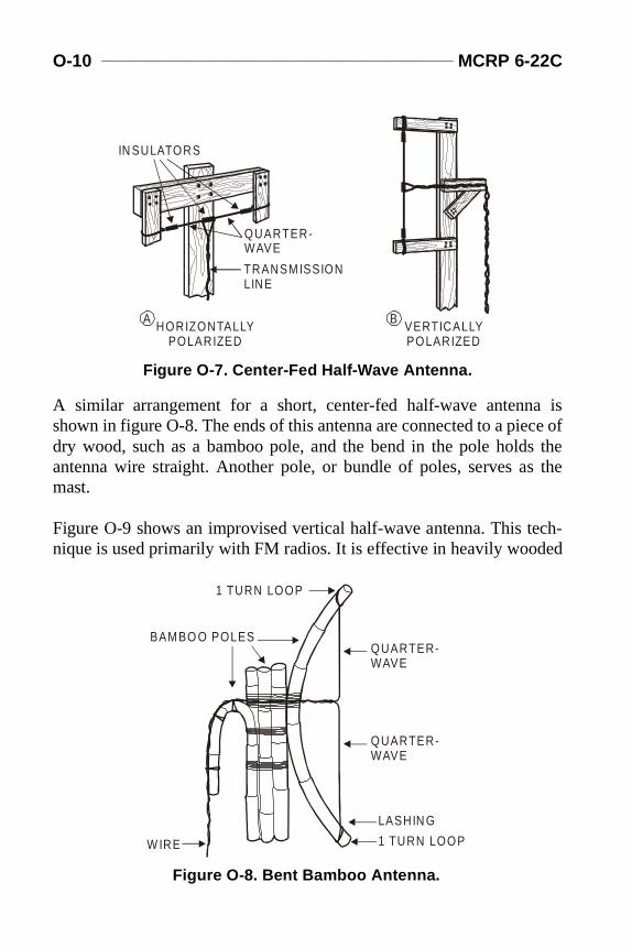
O-10 _____________________________________________ MCRP 6-22C
a isce ofs thes the
ech-ed
Appo.fm Page 10 Friday, June 25, 1999 11:17 AM
A similar arrangement for a short, center-fed half-wave antennshown in figure O-8. The ends of this antenna are connected to a piedry wood, such as a bamboo pole, and the bend in the pole holdantenna wire straight. Another pole, or bundle of poles, serves amast.
Figure O-9 shows an improvised vertical half-wave antenna. This tnique is used primarily with FM radios. It is effective in heavily wood
VERTICALLYPOLARIZED
HORIZONTALLYPOLARIZED
IN SULATORS
QUARTER-WAVE
TRANSMISSIONLINE
A B
Figure O-7. Center-Fed Half-Wave Antenna.
BAMBO O POLES
LASHIN G
W IRE
1 TURN LOOP
1 TURN LOOP
QUARTER-WAVE
QUARTER-WAVE
Figure O-8. Bent Bamboo Antenna.
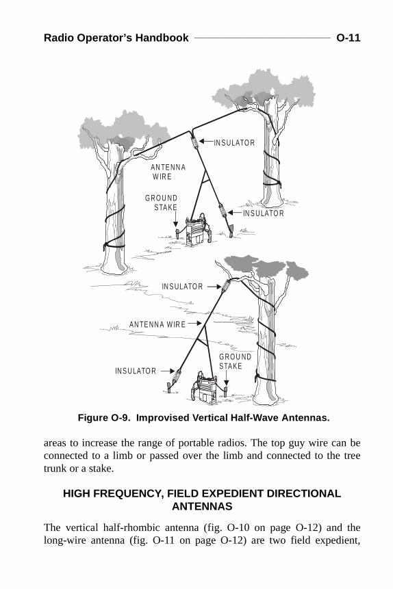
Radio Operator’s Handbook ____________________________ O-11
an be tree
theent,
Appo.fm Page 11 Friday, June 25, 1999 11:17 AM
areas to increase the range of portable radios. The top guy wire cconnected to a limb or passed over the limb and connected to thetrunk or a stake.
HIGH FREQUENCY, FIELD EXPEDIENT DIRECTIONAL ANTENNAS
The vertical half-rhombic antenna (fig. O-10 on page O-12) and long-wire antenna (fig. O-11 on page O-12) are two field expedi
G RO U ND STA KE
G RO U ND STA KE
IN S ULATO R
IN S ULATO R
IN S ULATO R
IN S ULATO R
AN TE NN A W IR E
AN TE NN A W IR E
Figure O-9. Improvised Vertical Half-Wave Antennas.
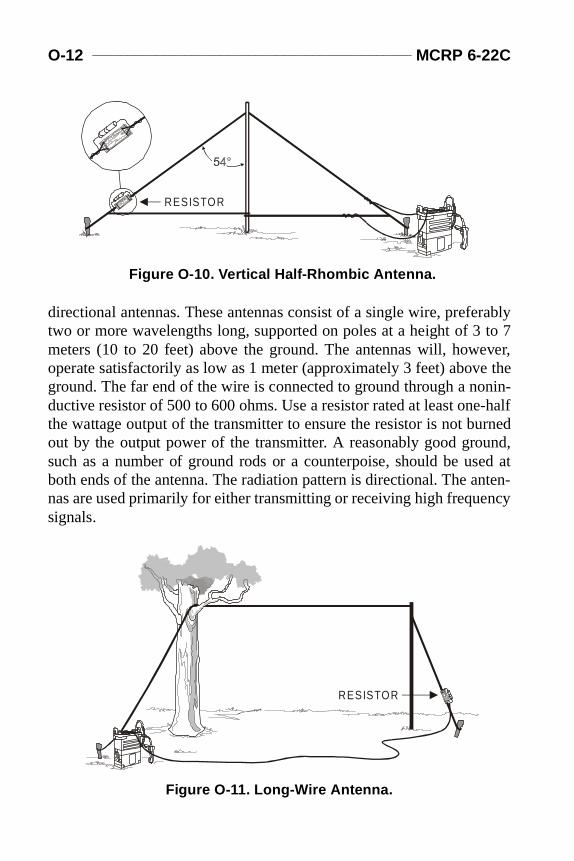
O-12 _____________________________________________ MCRP 6-22C
rably to 7ever,e thenin--halfrned
und,ed at
nten-ncy
Appo.fm Page 12 Friday, June 25, 1999 11:17 AM
directional antennas. These antennas consist of a single wire, prefetwo or more wavelengths long, supported on poles at a height of 3meters (10 to 20 feet) above the ground. The antennas will, howoperate satisfactorily as low as 1 meter (approximately 3 feet) abovground. The far end of the wire is connected to ground through a noductive resistor of 500 to 600 ohms. Use a resistor rated at least onethe wattage output of the transmitter to ensure the resistor is not buout by the output power of the transmitter. A reasonably good grosuch as a number of ground rods or a counterpoise, should be usboth ends of the antenna. The radiation pattern is directional. The anas are used primarily for either transmitting or receiving high frequesignals.
Figure O-10. Vertical Half-Rhombic Antenna.
RESISTOR
RESISTOR
Figure O-11. Long-Wire Antenna.
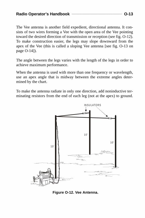
Radio Operator’s Handbook ____________________________ O-13
con-ting-12). the3 on
er to
ngth,deter-
ter-und.
Appo.fm Page 13 Friday, June 25, 1999 11:17 AM
The Vee antenna is another field expedient, directional antenna. It sists of two wires forming a Vee with the open area of the Vee pointoward the desired direction of transmission or reception (see fig. OTo make construction easier, the legs may slope downward fromapex of the Vee (this is called a sloping Vee antenna [see fig. O-1page O-14]).
The angle between the legs varies with the length of the legs in ordachieve maximum performance.
When the antenna is used with more than one frequency or waveleuse an apex angle that is midway between the extreme angles mined by the chart.
To make the antenna radiate in only one direction, add noninductiveminating resistors from the end of each leg (not at the apex) to gro
Figure O-12. Vee Antenna.
IN SU LATO RS
10 ’
10 ’10 ’

O-14 _____________________________________________ MCRP 6-22C
r rat-eingboth
Appo.fm Page 14 Friday, June 25, 1999 11:17 AM
The resistors should be approximately 500 ohms and have a poweing at least one-half that of the output power of the transmitter bused. Without the resistors, the antenna radiates bidirectionally, front and back.
The antenna must be fed by a balanced transmission line.
Figure O-13. Sloping Vee Antennas.
IN SULATORS
IN SULATOR
RESISTORS
RESISTOR
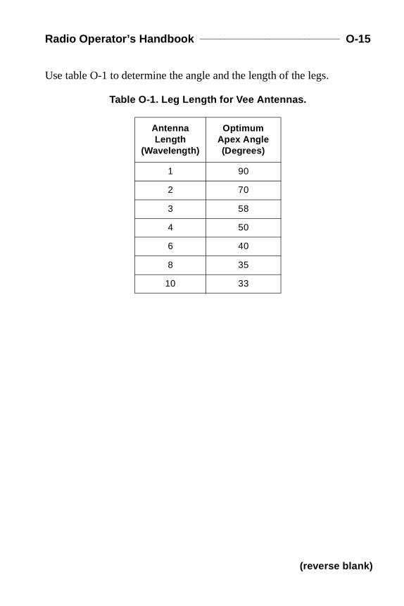
Radio Operator’s Handbook ____________________________ O-15
Appo.fm Page 15 Friday, June 25, 1999 11:17 AM
Use table O-1 to determine the angle and the length of the legs.
Table O-1. Leg Length for Vee Antennas.
Antenna Length
(Wavelen gth)
Optimum Apex An gle (Degrees)
1 90
2 70
3 58
4 50
6 40
8 35
10 33
(reverse blank)

Appendix P
Radio Operator’s Checklist
Before you operate any radio set, get the appropriate equipment techni-cal manual (TM) and carefully study the operating instructions. Refer tothe panel diagrams, connections diagrams, and the paragraphs coveringthe description of components during the preliminary starting procedure.Make sure that the proper cables are connected to the proper panel con-nectors, and that the controls are correctly set. Even the most experi-enced operators should check their preliminary procedures against theTM references from time to time to insure accuracy and avoid damagingthe equipment. Use the operational checklist and the equipment perfor-mance checklist to determine what to do to remedy any problemsencountered during starting procedures and operation.
STEPS IN OPERATING RADIO SETS
Radio sets issued to a unit vary in type according to the communicationsrequirements of the unit. For example, some sets may be completelycontained in one assembly, while others may consist of separate compo-nents that must be properly connected to assemble a complete radio set.The following steps are generally required in operating a radio set.
Check the Set for Completeness
Make sure that all the necessary components and accessories are on handand ready for use. Refer to the equipment basic issue items list in theTM. Never operate the transmitter without the antenna attached.
Inspect the Condition of the Knobs, Dials, Switches, and Controls
Look for knobs, dials, switches, and controls that are loose on theirshafts, bind when being operated, won’t operate, or are damaged in anyother way. Make corrections where possible or report the faulty

P-2 _______________________________________________ MCRP 6-22C
condition to the CIS officer or CIS chief. Make sure that all knobs andexterior parts are on the set. Immediately report any that are missing.
Check the Condition of Plugs, Receptacles, and Connectors
Do not attempt to connect the set for operation until you are sure that theplugs and connectors are clean and in good condition, and the recepta-cles to which they must be connected are also clean and in good condi-tion.
Check the Connections Diagrams
The connections diagrams in the equipment TM show the type and num-ber of cables required to interconnect the components of the radio set foreach type of operation. The radio set may be damaged if cables are con-nected to the wrong receptacles.
If the connectors don’t match, it is possible to physically damage thepins or sleeves of the connector.
If a cable is connected to a receptacle into which it fits but does notbelong, it may cause serious electrical damage to the equipment and, insome cases, injury to the operator.
Make Sure of Dial, Switch, and Control Settings
Some radio sets can be seriously damaged if the switches, dials, and con-trols are not set to the required initial settings before applying power ormaking the initial timing adjustments. Before applying power, check theequipment TM to be sure you performed all preliminary starting proce-dures. Be sure radios installed in vehicles are turned off before startingthe vehicle’s engine to avoid damage to radio equipment.
Follow the Starting Procedure
The equipment TM covers, in detail, the proper procedure for startingthe radio set. If there is a specific sequence for starting the set, it isdescribed in the manual. Perform the operations in the proper sequence.
Radio Operator’s Handbook ______________________________ P-3
Apply Power
After the proper connections are made, and all switches are properly set,power may be applied to the set.
Allow the Set to Warm Up
Radio sets usually require a warm-up period when first applying powerin order to stabilize the equipment. In some cases, it is possible to dam-age a set by attempting to operate a set without allowing a warm-upperiod. Most sets are protected against such damage, but it is foolish torisk damage to a radio set by trying to put it on the air before it is ready.
Tune to the Desired Frequency (Channel)
Tune the transmitter to the frequency of the desired channel according tothe procedures in the equipment TM. Use the methods that are given inthe TM to check for correct tuning.
Check the Set for Normal Operation
While the set is in operation, check the indicators frequently to be surethat the set is operating correctly. If anything unusual occurs duringoperation, investigate it immediately. When necessary, turn off thepower to the set and refer to the operational checklist and the equipmentperformance checklist in the equipment manual. If the corrections givenin the operational checklist and the equipment performance checklistwill not correct the trouble, report the condition to the unit electronicsmaintenance shop. Make sure that the condition of the set and the actiontaken are properly recorded on the maintenance records.
Use the Proper Procedure to Turn Off the Set
After operation (or if the set is being turned off because of improperoperation) make sure that the controls, switches, and dials are properlyset (this may not be required on some radios). Proceed to shut down thecomponents of the set in the sequence specified in the equipment man-ual. Simple radios may require nothing more than turning the power
P-4 _______________________________________________ MCRP 6-22C
switch to its OFF position, but more complex sets may require elaborateshutdown procedures.
Operating Hints
Use a handset or headset, rather than a loudspeaker, if the incoming sig-nal is weak. Make sure that the microphone or handset is in good condi-tion. Speak directly into the microphone; speak slowly and distinctly.
Make sure that the vehicle’s battery voltage (if radio set is vehicular-mounted) is within the correct range. Keep the engine running to chargethe battery. Move the set or the vehicle, if necessary, to improve recep-tion.
Lack of communications or poor communications may be caused by—
l Too great a distance between radio sets. l Poor choice of location (siting) at one or both ends of the circuit. l Terrain—hills or mountains. l Noise and interference. l Not enough transmitter power. l Defective equipment. l Improper adjustment of equipment. l Ineffective antenna. l Improper frequency assignment.
Poorly maintained equipment and improper operation can be just aseffective in preventing communications as excessive distance or moun-tainous terrain. To avoid problems, observe the following precautions atall times:
l Study the TMs for the equipment you are using. They provide com-plete operating instructions and maintenance procedures.
l Keep your radio set clean and dry. l Handle your radio set carefully.

rrentencytionssiblegram
cond
ters,
imetionilityemseter
nceuritytatesent
Time
inalcesscibelrrentinaletereter
stem
Appq.fm Page 1 Friday, June 25, 1999 10:53 AM
Appendix Q
Glossary
Section I. Acronyms
AC................................................................................ alternating cuAF ....................................................................................audio frequAM......................................................................... amplitude modulaASAP .......................................................................... as soon as poASIP.........................................advanced systems improvement pro
bps......................................................................................bits per se
C4I ............................... command, control, communications, compuand intelligence
CDT ...................................................................... Central Daylight TCEOI. ......................... communications-electronics operating instrucCEP ................................................................circular error of probabCIS ..........................................communications and information systcm..............................................................................................centimCOMINT..................................................... communications intelligeCOMSEC.......................................................... communications secCONUS............................................................. continental United SCOTS ...............................................commercial off-the-shelf equipmCST ....................................................................... Central Standard
DACT...................................... data automated communications termDAMA ..................................................demand assigned multiple acdb ................................................................................................... deDC........................................................................................ direct cuDCT .......................................................digital communications termdm ..............................................................................................decimdkm ...........................................................................................dekamDMS......................................................................digital message sy

Q-2 ______________________________________________ MCRP 6-22C
mentroup
ttackimetionntrolulse
ctionstempport Timerfare
lleropstionorcenual
hertzstem
encyhertz
eter
tiontionared
nterenter
ertzetercondwatt
Appq.fm Page 2 Friday, June 25, 1999 10:53 AM
DTE.....................................................................data terminal equipDTG ................................................................................. date-time g
EA ................................................................................... electronic aEDT....................................................................... Eastern Daylight TEEFI ........................................essential elements of friendly informaEMCON.......................................................................... emission coEMP ........................................................................electromagnetic pEP..............................................................................electronic proteEPLRS ................................enhanced position location reporting syES.....................................................................electronic warfare suEST ....................................................................... Eastern StandardEW ................................................................................electronic wa
FAC......................................................................... forward air controFLOT ..............................................................forward line of own troFM.......................................................................... frequency modulaFMF ............................................................................Fleet Marine FFMFM............................................................ Fleet Marine Force ma
GHz.............................................................................................gigaGPS .................................................................. global positioning sy
HF ..................................................................................... high frequHz.......................................................................................................hm ............................................................................................hectom
ID ......................................................................................... identificaIED................................................... imitative electromagnetic decepIR .................................................................................................. infr
JC2WC................................Joint Command and Control Warfare CeJSC.........................................................................Joint Spectrum C
KHz............................................................................................. kilohkm .............................................................................................. kilomkbps...........................................................................kilobytes per sekW................................................................................................ kilo
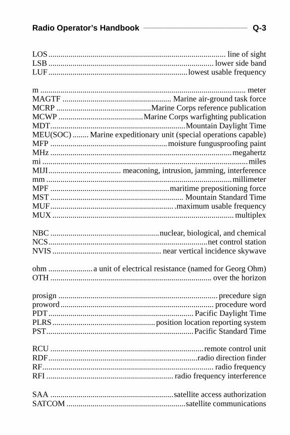
Radio Operator’s Handbook _____________________________ Q-3
ightbandency
eterrcetionionmeble)ainthertz
ilesnceeterrceimencylex
icalationave
hm)izon
signwordimetemTime
unitder
encyence
ationions
Appq.fm Page 3 Friday, June 25, 1999 10:53 AM
LOS........................................................................................ line of sLSB .................................................................................. lower side LUF..................................................................... lowest usable frequ
m ...................................................................................................... mMAGTF ...................................................... Marine air-ground task foMCRP ...............................................Marine Corps reference publicaMCWP ..........................................Marine Corps warfighting publicatMDT...................................................................Mountain Daylight TiMEU(SOC) ........ Marine expeditionary unit (special operations capaMFP ..........................................................moisture fungusproofing pMHz ..........................................................................................megami ......................................................................................................mMIJI.................................... meaconing, intrusion, jamming, interferemm ............................................................................................millimMPF ...........................................................maritime prepositioning foMST .................................................................. Mountain Standard TMUF............................................................. .maximum usable frequeMUX .......................................................................................... multip
NBC ......................................................nuclear, biological, and chemNCS...............................................................................net control stNVIS ...................................................... near vertical incidence skyw
ohm ......................a unit of electrical resistance (named for Georg OOTH ................................................................................ over the hor
prosign ............................................................................... precedureproword ............................................................................ procedure PDT........................................................................ Pacific Daylight TPLRS................................................... position location reporting sysPST.........................................................................Pacific Standard
RCU ............................................................................ remote controlRDF..........................................................................radio direction finRF..................................................................................... radio frequRFI ............................................................... radio frequency interfer
SAA .............................................................satellite access authorizSATCOM ...........................................................satellite communicat
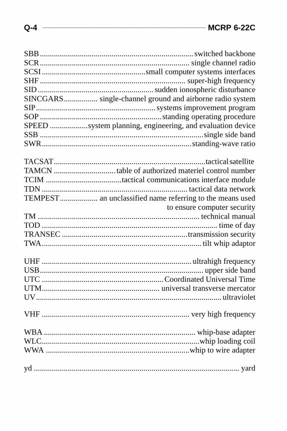
Q-4 ______________________________________________ MCRP 6-22C
boneradiofacesencyancetem
gramedureevice band ratio
llite beruleork
usedynual dayurityptor
ncybandime
catoriolet
ncy
pter coilpter
yard
Appq.fm Page 4 Friday, June 25, 1999 10:53 AM
SBB............................................................................. switched backSCR........................................................................... single channel SCSI ....................................................small computer systems interSHF ......................................................................... super-high frequSID .......................................................... sudden ionospheric disturbSINCGARS................. single-channel ground and airborne radio sysSIP............................................................ systems improvement proSOP .............................................................standing operating procSPEED ...................system planning, engineering, and evaluation dSSB ..................................................................................single sideSWR...........................................................................standing-wave
TACSAT............................................................................tactical sateTAMCN ............................... table of authorized materiel control numTCIM ......................................tactical communications interface modTDN ......................................................................... tactical data netwTEMPEST................... an unclassified name referring to the means
to ensure computer securitTM ................................................................................. technical maTOD ........................................................................................ time ofTRANSEC ...............................................................transmission secTWA................................................................................ tilt whip ada
UHF ........................................................................... ultrahigh frequeUSB.................................................................................. upper side UTC .............................................................Coordinated Universal TUTM........................................................... universal transverse merUV............................................................................................. ultrav
VHF .......................................................................... very high freque
WBA ............................................................................ whip-base adaWLC...............................................................................whip loadingWWA ........................................................................whip to wire ada
yd .......................................................................................................
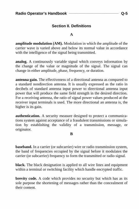
Radio Operator’s Handbook _____________________________ Q-5
ance
by can
d totio ininputtion.t the, the
ica-mula- or
m,s theal.
ent
itsent of
Appq.fm Page 5 Friday, June 25, 1999 10:53 AM
Section II. Definitions
A
amplitude modulation (AM). Modulation in which the amplitude of thecarrier wave is varied above and below its normal value in accordwith the intelligence of the signal being transmitted.
analog. A continuously variable signal which conveys information the change of the value or magnitude of the signal. The signalchange in either amplitude, phase, frequency, or duration.
antenna gain. The effectiveness of a directional antenna as comparea standard nondirection antenna. It is usually expressed as the radecibels of standard antenna input power to directional antenna power that will produce the same field strength in the desired direcFor a receiving antenna, the ratio of signal power values produced areceiver input terminals is used. The more directional an antenna ishigher is its gain.
authentication. A security measure designed to protect a communtions system against acceptance of a fraudulent transmissions or sition by establishing the validity of a transmission, message,originator.
B
baseband. In a carrier (or subcarrier) wire or radio transmission systethe band of frequencies occupied by the signal before it modulatecarrier (or subcarrier) frequency to form the transmitted or radio sign
black. The black designation is applied to all wire lines and equipmwithin a terminal or switching facility which handle encrypted traffic.
brevity code. A code which provides no security but which has assole purpose the shortening of messages rather than the concealmtheir content.
Q-6 ______________________________________________ MCRP 6-22C
snatedut-ptod inypto
ichity,
ica-
noirect) Aside-r, pro-
n ofom-n ofurityandion.
nyy a
anstingce
Appq.fm Page 6 Friday, June 25, 1999 10:53 AM
bulk encryption. An application of on-line cryptographic operationwhere the encryption and decryption process is performed at desigpoints of technical interface within a communications system; input-oput signals from various subscriber terminals thereby being crygraphically processed at these points. The operation is performebulk; i.e., two or more channels processed simultaneously by one crsecurity device.
C
call sign. Any combination of characters or pronounceable words whidentifies a communication facility, a command, an authority, an activor a unit; used primarily for establishing and maintaining communtions.
carrier. (1) The radio wave produced by a transmitter when there ismodulating signal, or any other wave, recurring series of pulses, or dcurrent capable of being modulated. Also called carrier wave. (2wave generated locally at a receiver that, when combined with the bands of a suppressed carrier transmission and a suitable detectoduces the modulating wave.
communications security (COMSEC). The protection resulting fromall measures designed to deny unauthorized persons informatiovalue which might be derived from the possession and study of telecmunications, or to mislead unauthorized persons in their interpretatiothe results of such possession and study. Communications secincludes cryptosecurity, transmission security, emission security, physical security of communications security materials and informat
critical frequency. The highest frequency at which a given wave at agiven time will, if transmitted vertically, be refracted back to earth blayer of the ionosphere.
cryptography. The art or science which pertains to the various meand methods for rendering plain text unintelligible, and reconverunintelligible texts into intelligible language; application of that scienby means other than cryptanalysis.
Radio Operator’s Handbook _____________________________ Q-7
ized byacters
nded aste,
nalel ofe dif-loga-eir
enceningina-
ionn ofntrol
c
-trum
onic
Appq.fm Page 7 Friday, June 25, 1999 10:53 AM
D
data. Representation of facts, concepts, or instructions in a formalmanner suitable for communication, interpretation, or processinghumans or by automatic means. Any representations such as charor analog quantities to which meaning is or might be assigned.
date-time group (DTG). The date and time, expressed in digits azone suffix, the message was prepared for transmission. (Expresssix digits followed by the zone suffix; first pair of digits denotes the dasecond pair the hours, third pair the minutes.)
decibel (dB). A unit used to express the magnitude of a change in sigor sound level. A change of three decibels is the change in power leva pure sine wave that is just barely detectable by the human ear. Thference in decibels between two signals is 10 times the common rithm of their ratio of powers or 20 times the common logarithm of thratio of voltages or currents. One decibel is one-tenth of a bel.
digital. A signal having discrete states, usually two, such as the presor absence of a voltage. The signal is given meaning by assignumerical values or other information to the various possible combtions of the discrete states of the signal.
directed net. A net in which no station other than the net control statcan communicate with any other station, except for the transmissiourgent messages, without first obtaining the permission of the net costation.
E
electromagnetic radiation. Radiation made up of oscillating electriand magnetic fields and propagated with the speed of light.
electronic warfare (EW). Any military action involving the use of electromagnetic and directed energy to control the electromagnetic specor to attack the enemy. The three major subdivisions within electr
Q-8 ______________________________________________ MCRP 6-22C
sup-
er net
ri-tinggiga-
en
yp tod of
ofal intudere-and
Fy):h000
Appq.fm Page 8 Friday, June 25, 1999 10:53 AM
warfare are: electronic attack, electronic protection, and electronic port measures.
F
free net. A net in which any station may communicate with any othstation in the same net without first obtaining permission from thecontrol station to do so.
frequency. The number of complete cycles per unit of time for a peodic quantity such as alternating current, sound waves, or vibraobjects. Frequency is expressed in hertz, kilohertz, megahertz, and hertz.
frequency band. A continuous range of frequencies extending betwetwo limiting frequencies.
Frequency hopping. A method of jumping from frequency to frequencin synchronization with one another in a random order at a rate of u100 times per second. Frequency hopping is the preferred methocommunication with SINCGARS radios.
frequency modulation (FM). Frequency modulation is the process varying the frequency (rather than the amplitude) of the carrier signaccordance with the variations of the modulating signals. The amplior power of the FM carrier does not vary during modulation. A fquency modulation system is practically immune to atmospheric man-made interference.
frequency spectrum designation. VLF (very low frequency): below 30kHz (0.03 MHz). LF (low frequency): 30-300 kHz (0.03-0.3 MHz). M(medium frequency): 300-3000 kHz (0.3-3 MHz). HF (high frequenc3-30 MHz. VHF (very high frequency): 30-300 MHz. UHF (ultra higfrequency): 300-3000 MHz. SHF (super high frequency): 3000-30,MHz (3-30 GHz). EHF (extremely high frequency): 30-300 GHz.
Radio Operator’s Handbook _____________________________ Q-9
rdi-. The theve isopo-
ady
a-onesin-
to
andn of
tendsd theate
Appq.fm Page 9 Friday, June 25, 1999 10:53 AM
G
ground wave. A radio wave that is propagated over the earth and is onarily affected by the presence of the ground and the troposphereground wave includes all of the components of a radio wave overearth except ionospheric and tropospheric waves. The ground warefracted because of variations in the dielectric constant of the trsphere, including the condition known as a surface duct.
guard. To maintain a continuous receiver watch with transmitter refor immediate use. A complete log is to be kept.
H
half-duplex—Refers to a mode of transmission in which communiction between two terminals occurs in either direction, but in only direction at a time. This is the typical mode of operation for tactical gle-channel radios.
hertz (Hz). A unit of frequency equal to one cycle per second.
I
imitative communication deception (ICD). The introduction of radia-tion into enemy systems which imitate the enemy’s emissions.
in the clear. In plain text. When cryptographic devices are not usedprotect a transmitted signal.
ionosphere. A region in the earth’s outer atmosphere where ions electrons are present in quantities sufficient to affect the propagatioHF radio waves. It begins about 30 miles above the earth and exabove 250 miles, with the height depending on the season of year antime of day. The chief layers of the ionosphere and their approximheights are: D layer—30 to 60 milesE layer—60 to 90 milesF layer—90 to 250 miles
Q-10 _____________________________________________ MCRP 6-22C
r or
, andbil-
ts.
ce of
nits
ct
olS.
diols is This
Appq.fm Page 10 Friday, June 25, 1999 10:53 AM
J
jamming (electromagnetic). The deliberate radiation, reradiation, oreflection of electromagnetic energy for the purpose of preventingreducing an enemy’s effective use of the electromagnetic spectrumwith the intent of degrading or neutralizing the enemy’s combat capaity.
L
line of sight (LOS). The straight unobstructed path between two poin
link. In communications, a general term used to indicate the existencommunications facilities between two points.
log. A chronological record of station events.
N
needline. A requirement to establish communications between two uor agencies.
net (communications). An organization of stations capable of direcommunications on a common channel or frequency.
net call sign. A call sign which represents all stations within a net.
net control station. A communications station designated to contrtraffic and enforce circuit discipline within a given net. Also called NC
O
obstacle gain. The increase in signal strength obtained over a long racommunications path where a mountain obstacle or range of hillocated about halfway between transmitting and receiving antennas.obstacle gain offsets some of the path losses normally expected.
Radio Operator’s Handbook ____________________________ Q-11
ionsns,
e byrder to be
bi-on-
ions,
-for-
int
ed soum-
ichce.
c-ur-
Appq.fm Page 11 Friday, June 25, 1999 10:53 AM
operating signals. Three letter groups used as necessary in connectwith operations or communications to convey orders, instructiorequests, reports, and information to facilitate communications.
P
precedence. In communications, a designation assigned to a messagthe originator to indicate to communications personnel the relative oof handling and to the addressee the order in which the message isnoted.
procedure sign (prosign). One or more letters or characters, or comnation thereof, used to facilitate communications by conveying in a cdensed standard form certain frequently used orders, instructrequests, and information related to communications.
procedure word (proword). A word or phrase limited to radio telephone procedure used to facilitate communication by conveying inmation in a condensed standard form.
Propagation. A phenomenon by which any wave moves from one poto another.
pulse code modulation (PCM). The form of modulation in which themodulating signal is sampled, and the sample quantitized and codthat each element or information consists of different kinds and/or nbers of pulses and spaces.
pulse position modulation (PPM). A form of pulse modulation inwhich intelligence is conveyed by varying the time interval by whsuccessive pulses are displayed from their normal times of occurren
push to talk operation. Voice communications on a circuit in one diretion at a time in which operation of a switch is required prior to and ding transmission.
Q-12 _____________________________________________ MCRP 6-22C
iceful
a-trament
and/
e toarth
on
r a two the
alted
ac-
Appq.fm Page 12 Friday, June 25, 1999 10:53 AM
R
radio frequency (RF). A frequency in which coherent electromagnetradiation of energy is useful for communications purposes. The usrange is from approximately 10 kilohertz to 100,000 megahertz.
radio silence. A condition in which all or certain radio equipment capble of radiation is kept inoperative. (In combined or U.S. joint or inService communications the frequency bands and/or types of equipaffected will be specified.)
red. Designation applied to transmission lines, equipment, systems,or areas passing unencrypted signals.
S
satellite communications. Use of communication satellites, passivreflecting belts of dipoles or needles, or reflecting orbiting balloonsextend the range of radio communications by returning signals to efrom the orbiting objective, with or without amplification.
simplex. Refers to a mode of operation in which communicatibetween two terminals can take place in only one direction.
skip distance. The minimum separation at which radio waves ovespecified frequency can be transmitted at a specific time betweenpoints on the earth by reflection from the regular ionized layers ofionosphere.
skip zone. A region, in relation to a given transmitter, in which no signwould be predicted, either due to direct repetition or due to reflecwaves.
sky wave. A radio wave that reaches the receiving location after refrtion from the ionosphere.
Radio Operator’s Handbook ____________________________ Q-13
ort of
nde cir-
intotrical
Appq.fm Page 13 Friday, June 25, 1999 10:53 AM
T
tactical radio net. A functional radio net used by a commander fimmediate and direct control of the fire and maneuver or movemenhis subordinate units.
traffic. All transmitted and received messages.
transceiver. A radio transmitter and receiver combined in one unit ahaving switching arrangements such as to permit use of one or morcuit components for both transmitting and receiving.
transducer. A device that transfers or changes one type of energy another form. An example is a loudspeaker, which changes elecenergy into acoustic (mechanical) energy.
(reverse blank)
Appendix R
References and Related Publications
Joint Publication (Joint Pub)
1-02 Department of Defense Dictionary of Military andAssociated Terms
Marine Corps Doctrinal Publication (MCDP)
6 Command and Control
Marine Corps Warfighting Publications (MCWPs)
6-2 MAGTF Command and Control Operations (under development)6-22 Communications and Information Systems
Marine Corps Reference Publications (MCRPs)
6-22A TALK II-SINCGARS Multiservice Communications Procedures for the Single-Channel Ground and Airborne Radio System
6-22B Multiservice Procedures for Spectrum Managementin a Joint Environment
6-22D Antenna Handbook (under development)
Army Field Manuals (FMs)
11-32 Combat Net Radio Operations24-11 Tactical Satellite Communications24-18 Tactical Single-Channel Radio Communications
Techniques24-19 Radio Operator’s Handbook
(reverse blank)
Appr.fm Page 1 Friday, June 25, 1999 10:52 AM