radio resource allocation for ofdma systems in high speed environments
TRANSCRIPT
748 IEEE JOURNAL ON SELECTED AREAS IN COMMUNICATIONS, VOL. 30, NO. 4, MAY 2012
Radio Resource Allocation for OFDMA Systems inHigh Speed Environments
Huiling Zhu, Member, IEEE,
Abstract—In high speed train (HST) system, real-time multi-media entertainments are very important applications in whicha data stream often contains packets with different quality ofservice requirements. For example, video stream encoded withscalability contains the base layer packets with high quality (HQ)bit error rate (BER) requirement and enhancement layers’ pack-ets with low quality (LQ) BER requirement. When a conventionalallocation approach, which only considers one BER constraintfor one data stream, is applied to orthogonal frequency divisionmultiple access (OFDMA) systems, the BER constraint will bethe strictest one among multiple requirements from differenttypes of packets, which leads to inefficient allocation when eachdata stream has multiple BER requirements. This paper aimsto develop novel resource allocation approach by consideringmultiple BER requirements for different types of packets inone data stream. In order to not only simplify the resourceallocation, but also to compensate for the channel estimationerror caused by Doppler shift in the HST environment, a propernumber of contiguous subcarriers are grouped into chunks andspectrum is allocated chunk by chunk. Simulation results showthat the developed resource allocation scheme outperforms theconventional scheme, particularly when the BER ratio of HQpackets to LQ packets is larger than one. Furthermore, inorder to reduce the complexity of resource allocation further,an empirical allocation scheme is proposed to allocate betterchunks to HQ packets. It is shown that the performance of theempirical allocation scheme is quite close to that of the optimalscheme.
Index Terms—Resource allocation; OFDMA systems; chunk-based allocation; minimization of transmit power; data packetswith multiple BER requirements; high speed trains.
I. INTRODUCTION
REAL-TIME multimedia entertainments are very impor-tant applications in the high speed train (HST) system
[1]. A data stream of this kind of applications can includepackets having different degrees of importance [2][3] in orderto suit to the variable wireless channel. For example, a real-time video stream encoded with scalability consists of thebase layer of packets and enhancement layers of packetswith different degrees of importance [2]. The base layer canbe independently decoded to provide coarse visual quality,whereas enhancement layers can be decoded to enhance visualquality only when the base layer is available. Since thebase layer is the basis in the video decoding, the reliabletransmission of the base layer is extremely important. Thus,the base layer should have a smaller bit error rate (BER) orhigh quality (HQ) requirement than the enhancement layers
Manuscript received 1 May 2011; revised 1 August 2011.The author is with the Broadband and Wireless Communications Re-
search Group, University of Kent, Canterbury, Kent, CT2 7NT, UK (e-mail:[email protected]).Digital Object Identifier 10.1109/JSAC.2012.120509.
with relative low quality (LQ) requirements. In conventionalresource allocation, only one BER constraint is considered[4][5]. If applying the conventional approach to the datastreams with multiple BER requirements, the strictest oneout of multiple BER requirements has to be chosen as theBER constraint for all types of packets, which leads toan inefficient allocation algorithm. Since allocating resourceefficiently is very important in the wireless system, in thispaper, resource allocation with the consideration of multipleBER requirements in one data stream is considered in the HSTsystem.
Orthogonal frequency division multiplexing (OFDM) hasbeen proposed for wireless transmission, since it can con-vert the frequency selective channel to multiple flat fadingchannels and eliminate inter-symbol interference in broadbandchannels. In a downlink OFDM-based orthogonal frequencydivision multiple access (OFDMA) system, a proper resourceallocation scheme can efficiently allocate subcarriers to users,adapt data rate in each subcarrier and control transmit powerto achieve high system performance. Therefore, OFDMAtechnique is adopted in the HST system. The main aim ofresource allocation can be either to maximize the systemthroughput or minimize the transmit power, while satisfyingsome constraints, such as BER, transmit power, data rates andfairness [6]-[9]. In [10], combined with admission control, thesystem capacity was effectively improved in LTE networks.Considering that energy efficiency is one of focuses in fu-ture wireless systems, a novel resource allocation scheme isproposed in this paper to minimize the total transmit powerby using multiple BER constraints in resource allocationformulation. In this scheme, HQ packets and LQ packetsare queued into individual buffers. The resource allocationis carried out on the HQ and LQ packets separately throughtheir separate buffers with the objective of minimizing the totaltransmit power.
In the HST environment [11], because of the effect ofDoppler shift, it is difficult to have perfect channel estimation.Imperfect channel estimation will impair system performance[12][13]. It is shown in this paper that compared with allo-cating resource subcarrier by subcarrier, chunk-based resourceallocation, which groups multiple adjacent subcarriers into achunk and allocates spectrum chunk by chunk, can achievebetter throughput when a proper number of subcarriers aregrouped into chunks. Furthermore, chunk-based resource allo-cation can greatly reduce the complexity of resource allocation[14][15]. Therefore, the chunk-based resource allocation isalso adopted for the resource allocation in the HST system.
This paper is organized as follows. In Section II, the system
0733-8716/12/$25.00 c© 2012 IEEE
ZHU: RADIO RESOURCE ALLOCATION FOR OFDMA SYSTEMS IN HIGH SPEED ENVIRONMENTS 749
One data stream
Allocation period
HQ packet with BER constraint of
LQ packet with BER constraint of
)(H
)(L
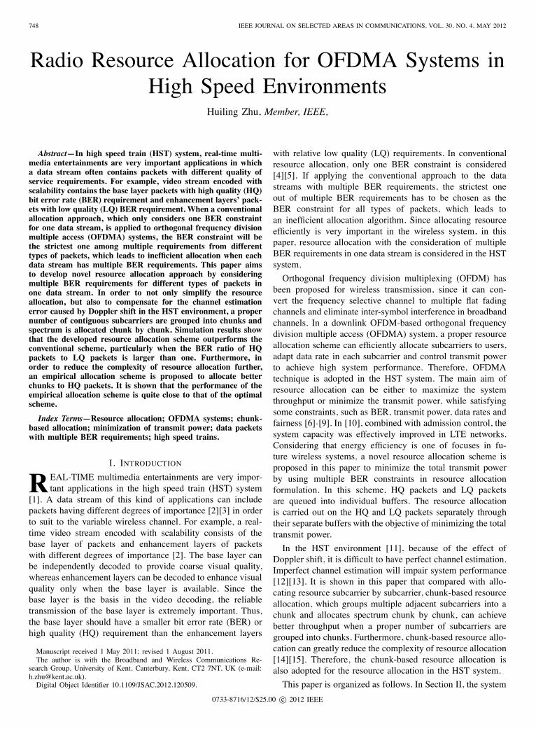
Fig. 1. Data stream with HQ and LQ packets
model is given and the chunk-based resource allocation iscompared with subcarrier-based resource allocation when theeffect of Doppler shift is considered. Then, the optimizationof chunk-based resource allocation by considering multipleBER constraints is presented in Section III, with descriptionsof optimal and empirical double-queue resource allocationapproaches. Representative simulation results are shown inSection IV. Finally, conclusions are drawn in Section V.
II. SYSTEM MODEL
Resource allocation in OFDMA systems has three basictasks: subcarrier allocation, rate adaptation, and power control.Subcarrier allocation allocates subcarriers among active usersto enable efficient usage of subchannels according to channelconditions and other factors. Rate adaptation, i.e. adaptivemodulation, provides potential to vary the number of trans-mitted bits per OFDM symbol for each subchannel accordingto the instantaneous channel quality, while maintaining anacceptable BER. Power control effectively distributes thetransmit power over subchannels so as to maintain the linkquality. Thus, effective resource allocation approach is crucialfor providing energy efficiency wireless transmissions.For simple analysis, each data stream is assumed to have
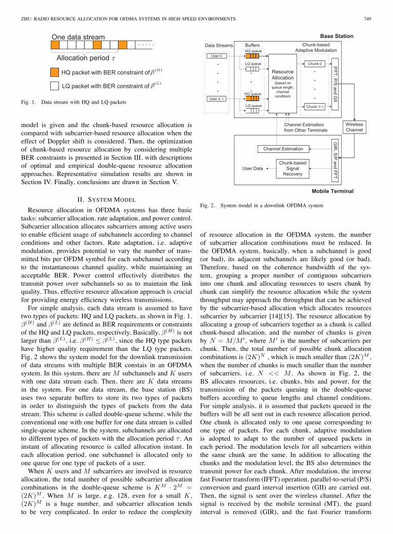
two types of packets: HQ and LQ packets, as shown in Fig. 1.β(H) and β(L) are defined as BER requirements or constraintsof the HQ and LQ packets, respectively. Basically, β(H) is notlarger than β(L), i.e. β(H) ≤ β(L), since the HQ type packetshave higher quality requirement than the LQ type packets.Fig. 2 shows the system model for the downlink transmissionof data streams with multiple BER constais in an OFDMAsystem. In this system, there are M subchannels and K userswith one data stream each. Then, there are K data streamsin the system. For one data stream, the base station (BS)uses two separate buffers to store its two types of packetsin order to distinguish the types of packets from the datastream. This scheme is called double-queue scheme, while theconventional one with one buffer for one data stream is calledsingle-queue scheme. In the system, subchannels are allocatedto different types of packets with the allocation period τ . Aninstant of allocating resource is called allocation instant. Ineach allocation period, one subchannel is allocated only toone queue for one type of packets of a user.When K users and M subcarriers are involved in resource
allocation, the total number of possible subcarrier allocationcombinations in the double-queue scheme is KM · 2M =(2K)M . When M is large, e.g. 128, even for a small K ,(2K)M is a huge number, and subcarrier allocation tendsto be very complicated. In order to reduce the complexity
User 0
User K-1
Data Streams Buffers
ResourceAllocation(based on
queue length,channelcondition)
Chunk 0
Chunk N-1
IFFT,P/Sand
GII
WirelessChannel
GIR,S/Pand
FFT
Chunk-basedSignalRecovery
User Data
Mobile Terminal
Base StationChunk-based
Adaptive ModulationHQ queue
LQ queue
HQ queue
LQ queue
Channel Estimation
Channel Estimationfrom Other Terminals
Fig. 2. System model in a downlink OFDMA system
of resource allocation in the OFDMA system, the numberof subcarrier allocation combinations must be reduced. Inthe OFDMA system, basically, when a subchannel is good(or bad), its adjacent subchannels are likely good (or bad).Therefore, based on the coherence bandwidth of the sys-tem, grouping a proper number of contiguous subcarriersinto one chunk and allocating resources to users chunk bychunk can simplify the resource allocation while the systemthroughput may approach the throughput that can be achievedby the subcarrier-based allocation which allocates resourcessubcarrier by subcarrier [14][15]. The resource allocation byallocating a group of subcarriers together as a chunk is calledchunk-based allocation, and the number of chunks is givenby N = M/M ′, where M ′ is the number of subcarriers perchunk. Then, the total number of possible chunk allocationcombinations is (2K)N , which is much smaller than (2K)M ,when the number of chunks is much smaller than the numberof subcarriers, i.e. N << M . As shown in Fig. 2, theBS allocates resources, i.e. chunks, bits and power, for thetransmission of the packets queuing in the double-queuebuffers according to queue lengths and channel conditions.For simple analysis, it is assumed that packets queued in thebuffers will be all sent out in each resource allocation period.One chunk is allocated only to one queue corresponding toone type of packets. For each chunk, adaptive modulationis adopted to adapt to the number of queued packets ineach period. The modulation levels for all subcarriers withinthe same chunk are the same. In addition to allocating thechunks and the modulation level, the BS also determines thetransmit power for each chunk. After modulation, the inversefast Fourier transform (IFFT) operation, parallel-to-serial (P/S)conversion and guard interval insertion (GII) are carried out.Then, the signal is sent over the wireless channel. After thesignal is received by the mobile terminal (MT), the guardinterval is removed (GIR), and the fast Fourier transform
750 IEEE JOURNAL ON SELECTED AREAS IN COMMUNICATIONS, VOL. 30, NO. 4, MAY 2012
(FFT) operation is performed after serial-to-parallel (S/P)conversion. Afterwards, the channel conditions of subchannelsare estimated. The average of the estimated fading factors ofsubchannels within a chunk is used as the estimated channelcondition of the chunk and is fed back by the MT to the BSto carry out the resource allocation. On the other hand, thereceived signal is demodulated by the MT from the allocatedchunks. Finally, the user data are obtained.In the wireless channel, each subchannel is assumed to be
a Rayleigh fading channel [16] which introduces an additivewhite Gaussian noise (AWGN) with a double-sided powerspectral density of N0/2. hk,m is defined as the frequencyresponse of the kth user on the mth subchannel with unitaryvariance i.e. E{h∗
k,mhk,m} = 1, where (•)∗ stands forcomplex conjugate. hk,m is complex Gaussian distributed andits magnitude (or fading factor), αk,m, is Rayleigh distributedwith E{α2
k,m} = 1, for all k and m. It is assumed hk,m
remains unchanged in each allocation period. Furthermore,hk,m and hk′,m are assumed to be independent for k �= k′.The wireless channel is assumed to be frequency selective
and the correlation coefficient between any two subchannels,e.g. the m1th and m2th subchannels, of one user is the samefor all users, given by [17]
ρm1,m2 = E{h∗
k,m1hk,m2
}=
1√1 +(
(m1−m2)·Δffc
)2, (1)
where fc is the channel coherence bandwidth, and Δf is thefrequency separation between two adjacent subcarriers.Depending on the channel conditions, adaptive modulation
is adopted in order to achieve high performance. AssumingL to be the modulation level, L-ary quadrature amplitudemodulation (QAM) is employed as the modulation scheme,and L takes values from the following set,
Lb = {0, · · · , 2b, · · · , 2bm} = {0, · · · , Lb, · · · , Lbm}, (2)
where b is an even number and represents the number of totalbits in one OFDM symbol in a subcarrier and
Lb ={
0, b = 02b, b is even and 0 < b ≤ bm
. (3)
When b = 0, the modulation level is zero and no transmis-sion is made. That is, the power allocated to this subcarrier iszero. When b > 0, the number of bits per OFDM symbol isb = log2 Lb. When b = bm, the subcarrier achieves the highestbits, bm, and the highest modulation level, Lbm = 2bm . Thus,the set of bits corresponding to the set L is given by
B = {0, · · · , b, · · · , bm}. (4)
If the mth subcarrier is allocated to the kth user with themodulation level lk,m and the assigned power εk,m per OFDMsymbol, the instantaneous BER, β(k, m), of the kth user onthemth subcarrier can be approximated by a closed form [18]:
β(k, m) ≈ 0.2exp
(c · εk,m · Ts · α2
k,m
lk,m − 1
), (5)
where Ts is the OFDM symbol duration, and c = −1.6/N0.
From (5), the modulation level and transmit power perOFDM symbol can be determined as
lk,m =c · εk,m · Ts · α2
k,m
ln[5β(k, m)]+ 1, (6)
where ln[·] stands for the nature logarithm function, and
εk,m = ln[5β(k, m)] · lk,m − 1c · Ts · α2
k,m
, (7)
respectively. It can be seen from (6) that the modulationlevel, lk,m, is proportional to the channel quality (or fadingfactor), α2
k,m, and from (7) that the transmit power is inverselyproportional to the channel quality.In the chunk-based resource allocation, the modulation level
(or transmit power per subcarrier) is the same for subcarrierswithin one chunk. Defining lk,n and εk,n as the modulationlevel and the assigned power per subcarrier in the nth chunkfor the kth user, it obtains lk,m = lk,n and ε = εk,n, wherem = nM ′, · · · , (n + 1)M ′ − 1. Therefore, the average BER,βchunk(k, n), of the kth user in the nth chunk is given by
βchunk(k, n) =1
M ′∑(n+1)M ′−1
m=nM ′ β(k, m). (8)
Substituting β(k, m) in (8) by (5), one obtains
βchunk(k, n) =1
M ′
(n+1)M′−1Xm=nM′
0.2exp
c · Ts · εk,n · α2
k,m
lk,n − 1
!
= 0.2exp
„c · Ts · εk,n
lk,n − 1· α2
k,n
«, (9)
where αk,n is defined as chunk fading factor, given by
α2k,n =
lk,n − 1c · Ts · εk,n
·
ln
⎧⎨⎩ 1
M ′
(n+1)M ′−1∑m=nM ′
exp
(c · Ts · εk,n · α2
k,m
lk,n − 1
)⎫⎬⎭ . (10)
Given the BER constraint, βchunk(k, n), and transmit power,εk,n, the modulation level lk,n can be derived from (9) bytaking ln function on both sides of (9).In the HST system, the Doppler shift can cause the channel
estimation error, which will impair the system performance.According to [19][20], with the minimum mean square error(MMSE) associated optimal channel estimator, the channelestimation error on each subchannel can be assumed to beGaussian distributed and its variance is related to the Dopplershift, which is given by
σ2e =
11 + SNR · (Δf/Bd)
(11)
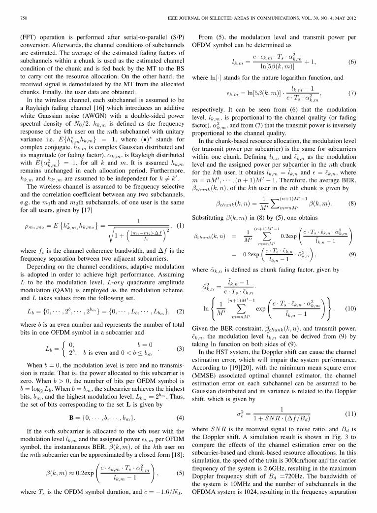
where SNR is the received signal to noise ratio, and Bd isthe Doppler shift. A simulation result is shown in Fig. 3 tocompare the effects of the channel estimation error on thesubcarrier-based and chunk-based resource allocations. In thissimulation, the speed of the train is 300km/hour and the carrierfrequency of the system is 2.6GHz, resulting in the maximumDoppler frequency shift of Bd =720Hz. The bandwidth ofthe system is 10MHz and the number of subchannels in theOFDMA system is 1024, resulting in the frequency separation
ZHU: RADIO RESOURCE ALLOCATION FOR OFDMA SYSTEMS IN HIGH SPEED ENVIRONMENTS 751
5 10 15 20 25 305.5
6
6.5
7
7.5
8
The Number of Subcarriers per Chunk
Ave
rage
Thr
ough
put (
bits
/sym
bol)
Number of Users = 3
fc =20Δf
Chunk−based result
Subcarrier−based result
Fig. 3. Performance comparisons between the subcarrier-based and chunk-based resource allocations
of Δf =9.7KHz between two adjacent subcarriers. AssumingSNR is 10dB, the channel estimation error from (11) is 1.3%.It can be seen that when the number of subcarriers per chunkis properly chosen, e.g. smaller than 20, the chunk-basedresource allocation outperforms the subcarrier-based resourceallocation in the average throughput. The main reason is that inthe subcarrier-based resource allocation, the estimation erroris accumulated over subcarriers in the system. However, forthe chunk-based resource allocation, the estimation error overa chunk is affected by the correlation between subchannels[21] and can be compensated by averaging the channel es-timation over the chunk. Therefore, selecting proper numberof subcarriers per chunk can not only simplify the resourceallocation, but also improve the system performance comparedwith the subcarrier-based resource allocation. αk,n in (10) isassumed to be independent on lk,n and εk,n. α2
k,n is difficultto evaluate because in (10), it is involved with the parameters:modulation level, lk,n, and transmit power, εk,n, which areunknown before chunk allocation. However, considering that{α2
k,m} are highly correlated to each other within a chunk, itis proved in Appendix A that α2
k,n can be approximated bythe average of the square of the channel fading factors withinthe chunk:
α2k,n ≈ 1
M ′∑(n+1)M ′−1
m=nM ′ α2k,m. (12)
Similar to (6) and (7), given the BER constraint β =βchunk(k, n) for all chunks, the modulation level, lk,n andthe transmit power per subcarrier, εk,n, are given by
lk,n =c · Ts · εk,n · α2
k,n
ln(5β)+ 1, (13)
and
εk,n = f(β, bk,n, αk,n) = ln(5β) · 2bk,n − 1c · Ts · α2
k,n
, (14)
where bk,n = log2 lk,n stands for the number of bits persubcarrier of the kth user in the nth chunk in an OFDM
symbol. And the transmit power for the kth user over thenth chunk is given by M ′ · εk,n. It can be seen from (13) and(14) that, given the BER constraint, β, within a chunk, themodulation level and the transmit power can be determinedaccording to the chunk fading factor, αk,n.
III. DOUBLE-QUEUE RESOURCE ALLOCATION
As described above, packets from a data stream are dividedinto the HQ and LQ packets and are queued in two differentbuffers. D
(H)k and D
(L)k are defined as queue lengths (back-
logged data in bits) of the kth user at an allocation instantin the two buffers, respectively. Assuming the sum of all thedata in the queues, i.e.
∑K−1k=0
(D
(H)k + D
(L)k
), is less than the
instantaneous channel capacity (i.e. N ·M ′ ·bm ·τ/Ts, where τis the allocation period), resource allocation mechanism willallocate chunks among all users to empty each user’s twobuffers at each allocation instant. That is, for each user, chunksmust be chosen along with appropriate modulation levels andtransmit power to transmit the user’s bits queued in the twobuffers in the allocation period. Since all the modulation levelswithin a chunk are unchanged in one allocation period, thedata per symbol for the kth user to transmit in an allocationperiod areQ
(H)k = D
(H)k ·Ts/τ andQ
(L)k = D
(L)k ·Ts/τ bits for
the two types, respectively. Regarding the resource allocationoptimization among all users, our aim is to minimize thetotal transmit power, while serving data streams in real timemanner. The minimization problem can be formulated asfollows
Ptotal = minbk,n∈B
{∑K−1
k=0
∑N−1
n=0
∑1
q=0ρk,n,q · M ′ · εk,n,q}
= minbk,n∈B
{K−1∑k=0
N−1∑n=0
1∑q=0
ρk,n,qf(βq, bk,n, αk,n)}, (15a)
subject to
ρk,n,q = {0, 1} and∑K−1
k=0
∑1
q=0ρk,n,q = 1 (15b)
∑N−1
n=0ρk,n,0 · M ′ · bk,n = Q
(H)k , (15c)
∑N−1
n=0ρk,n,1 · M ′ · bk,n = Q
(L)k , (15d)
where q is the buffer index with q = 0 and 1 correspondingto the HQ and LQ queues, respectively. bk,n is the allocatednumber of bits per subcarrier at the allocation instant for thekth user in the nth chunk. Set B is given by (4). εk,n,q =f(βq, bk,n, αk,n) is the transmit power per subcarrier assignedto the qth queue of the kth user in the nth chunk and is givenby (14) by substituting βq with β(H) for the HQ queue orβ(L) for the LQ queue, respectively. ρk,n,q shows whetherthe nth chunk is allocated to the qth buffer of the kth user.Constraint (15b) ensures that any chunk is allocated only toone buffer, associated with one user. For example, if the nthchunk is allocated to the HQ queue of the kth user, one obtainsρk,n,0 = 1, ρk,n,1 = 0 and ρk′,n,q = 0 for k′ �= k. (15c) and(15d) guarantee that all data in all buffers will be allocatedwith resources at the allocation instant.
752 IEEE JOURNAL ON SELECTED AREAS IN COMMUNICATIONS, VOL. 30, NO. 4, MAY 2012
A. One User
If there is only one user (e.g. the zeroth user) in the system,the transmit power minimization problem is given as follows
Ptotal = minb0,n∈B
{M ′N−1∑n=0
1∑q=0
ρ0,n,qf(βq, b0,n, α0,n)}, (16a)
subject to
ρ0,n,q = {0, 1} and∑1
q=0ρ0,n,1 = 1 (16b)
∑N−1
n=0ρ0,n,0 · M ′ · b0,n = Q
(H)0 , (16c)
∑N−1
n=0ρ0,n,1 · M ′ · b0,n = Q
(L)0 . (16d)
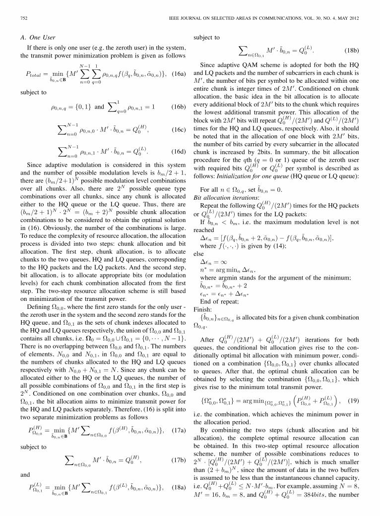
Since adaptive modulation is considered in this systemand the number of possible modulation levels is bm/2 + 1,there are (bm/2+1)N possible modulation level combinationsover all chunks. Also, there are 2N possible queue typecombinations over all chunks, since any chunk is allocatedeither to the HQ queue or the LQ queue. Thus, there are(bm/2 + 1)N · 2N = (bm + 2)N possible chunk allocationcombinations to be considered to obtain the optimal solutionin (16). Obviously, the number of the combinations is large.To reduce the complexity of resource allocation, the allocationprocess is divided into two steps: chunk allocation and bitallocation. The first step, chunk allocation, is to allocatechunks to the two queues, HQ and LQ queues, correspondingto the HQ packets and the LQ packets. And the second step,bit allocation, is to allocate appropriate bits (or modulationlevels) for each chunk combination allocated from the firststep. The two-step resource allocation scheme is still basedon minimization of the transmit power.Defining Ω0,0, where the first zero stands for the only user -
the zeroth user in the system and the second zero stands for theHQ queue, and Ω0,1 as the sets of chunk indexes allocated tothe HQ and LQ queues respectively, the union of Ω0,0 and Ω0,1
contains all chunks, i.e. Ω0 = Ω0,0 ∪Ω0,1 = {0, · · · , N − 1}.There is no overlapping between Ω0,0 and Ω0,1. The numbersof elements, N0,0 and N0,1, in Ω0,0 and Ω0,1 are equal tothe numbers of chunks allocated to the HQ and LQ queuesrespectively with N0,0 + N0,1 = N . Since any chunk can beallocated either to the HQ or the LQ queues, the number ofall possible combinations of Ω0,0 and Ω0,1 in the first step is2N . Conditioned on one combination over chunks, Ω0,0 andΩ0,1, the bit allocation aims to minimize transmit power forthe HQ and LQ packets separately. Therefore, (16) is split intotwo separate minimization problems as follows
P(H)Ω0,0
= minb0,n∈B
{M ′∑n∈Ω0,0
f(β(H), b0,n, α0,n)}, (17a)
subject to ∑n∈Ω0,0
M ′ · b0,n = Q(H)0 , (17b)
and
P(L)Ω0,1
= minb0,n∈B
{M ′∑n∈Ω0,1
f(β(L), b0,n, α0,n)}, (18a)
subject to ∑n∈Ω0,1
M ′ · b0,n = Q(L)0 . (18b)
Since adaptive QAM scheme is adopted for both the HQand LQ packets and the number of subcarriers in each chunk isM ′, the number of bits per symbol to be allocated within oneentire chunk is integer times of 2M ′. Conditioned on chunkallocation, the basic idea in the bit allocation is to allocateevery additional block of 2M ′ bits to the chunk which requiresthe lowest additional transmit power. This allocation of theblock with 2M ′ bits will repeatQ(H)
0 /(2M ′) andQ(L)/(2M ′)times for the HQ and LQ queues, respectively. Also, it shouldbe noted that in the allocation of one block with 2M ′ bits,the number of bits carried by every subcarrier in the allocatedchunk is increased by 2bits. In summary, the bit allocationprocedure for the qth (q = 0 or 1) queue of the zeroth userwith required bits Q
(H)0 or Q
(L)0 per symbol is described as
follows: Initialization for one queue (HQ queue or LQ queue):
For all n ∈ Ω0,q, set b0,n = 0.Bit allocation iterations:Repeat the followingQ
(H)0 /(2M ′) times for the HQ packets
or Q(L)0 /(2M ′) times for the LQ packets:
If b0,n < bm, i.e. the maximum modulation level is notreached
Δεn = [f(βq, b0,n + 2, α0,n) − f(βq, b0,n, α0,n)],where f(·, ·, ·) is given by (14);
elseΔεn = ∞n∗ = arg minn Δεn,where argmin stands for the argument of the minimum;b0,n∗ = b0,n∗ + 2εn∗ = εn∗ + Δεn∗
End of repeat;Finish:{b0,n}n∈Ω0,q is allocated bits for a given chunk combination
Ω0,q .
After Q(H)0 /(2M ′) + Q
(L)0 /(2M ′) iterations for both
queues, the conditional bit allocation gives rise to the con-ditionally optimal bit allocation with minimum power, condi-tioned on a combination {Ω0,0, Ω0,1} over chunks allocatedto queues. After that, the optimal chunk allocation can beobtained by selecting the combination {Ω0,0, Ω0,1}, whichgives rise to the minimum total transmit power.
{Ω∗0,0, Ω
∗0,1} = argmin{Ω∗
0,0,Ω∗0,1}(P
(H)Ω0,0
+ P(L)Ω0,1
), (19)
i.e. the combination, which achieves the minimum power inthe allocation period.By combining the two steps (chunk allocation and bit
allocation), the complete optimal resource allocation canbe obtained. In this two-step optimal resource allocationscheme, the number of possible combinations reduces to2N · [Q(H)
0 /(2M ′) + Q(L)0 /(2M ′)], which is much smaller
than (2 + bm)N , since the amount of data in the two buffersis assumed to be less than the instantaneous channel capacity,i.e. Q(H)
0 +Q(L)0 ≤ N ·M ′ ·bm. For example, assuming N = 8,
M ′ = 16, bm = 8, and Q(H)0 + Q
(L)0 = 384bits, the number
ZHU: RADIO RESOURCE ALLOCATION FOR OFDMA SYSTEMS IN HIGH SPEED ENVIRONMENTS 753
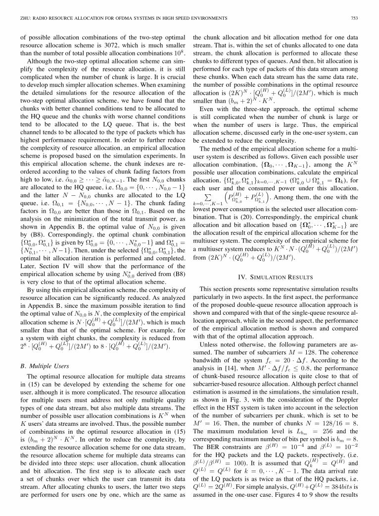
of possible allocation combinations of the two-step optimalresource allocation scheme is 3072, which is much smallerthan the number of total possible allocation combinations 108.Although the two-step optimal allocation scheme can sim-
plify the complexity of the resource allocation, it is stillcomplicated when the number of chunk is large. It is crucialto develop much simpler allocation schemes. When examiningthe detailed simulations for the resource allocation of thetwo-step optimal allocation scheme, we have found that thechunks with better channel conditions tend to be allocated tothe HQ queue and the chunks with worse channel conditionstend to be allocated to the LQ queue. That is, the bestchannel tends to be allocated to the type of packets which hashighest performance requirement. In order to further reducethe complexity of resource allocation, an empirical allocationscheme is proposed based on the simulation experiments. Inthis empirical allocation scheme, the chunk indexes are re-ordered according to the values of chunk fading factors fromhigh to low, i.e. α0,0 ≥ · · · ≥ α0,N−1. The first N0,0 chunksare allocated to the HQ queue, i.e. Ω0,0 = {0, · · · , N0,0 − 1}and the latter N − N0,0 chunks are allocated to the LQqueue, i.e. Ω0,1 = {N0,0, · · · , N − 1}. The chunk fadingfactors in Ω0,0 are better than those in Ω0,1. Based on theanalysis on the minimization of the total transmit power, asshown in Appendix B, the optimal value of N0,0 is givenby (B8). Correspondingly, the optimal chunk combination{Ω∗
0,0, Ω∗0,1} is given by Ω∗
0,0 = {0, · · · , N∗0,0−1} and Ω∗
0,1 ={N∗
0,1, · · · , N−1}. Then, under the selected {Ω∗0,0, Ω
∗0,1}, the
optimal bit allocation iteration is performed and completed.Later, Section IV will show that the performance of theempirical allocation scheme by using N∗
0,0 derived from (B8)is very close to that of the optimal allocation scheme.By using this empirical allocation scheme, the complexity of
resource allocation can be significantly reduced. As analyzedin Appendix B, since the maximum possible iteration to findthe optimal value ofN0,0 is N , the complexity of the empiricalallocation scheme is N · [Q(H)
0 +Q(L)0 ]/(2M ′), which is much
smaller than that of the optimal scheme. For example, fora system with eight chunks, the complexity is reduced from28 · [Q(H)
0 + Q(L)0 ]/(2M ′) to 8 · [Q(H)
0 + Q(L)0 ]/(2M ′).
B. Multiple Users
The optimal resource allocation for multiple data streamsin (15) can be developed by extending the scheme for oneuser, although it is more complicated. The resource allocationfor multiple users must address not only multiple qualitytypes of one data stream, but also multiple data streams. Thenumber of possible user allocation combinations is KN whenK users’ data streams are involved. Thus, the possible numberof combinations in the optimal resource allocation in (15)is (bm + 2)N · KN . In order to reduce the complexity, byextending the resource allocation scheme for one data stream,the resource allocation scheme for multiple data streams canbe divided into three steps: user allocation, chunk allocationand bit allocation. The first step is to allocate each usera set of chunks over which the user can transmit its datastream. After allocating chunks to users, the latter two stepsare performed for users one by one, which are the same as
the chunk allocation and bit allocation method for one datastream. That is, within the set of chunks allocated to one datastream, the chunk allocation is performed to allocate thesechunks to different types of queues. And then, bit allocation isperformed for each type of packets of this data stream amongthese chunks. When each data stream has the same data rate,the number of possible combinations in the optimal resourceallocation is (2K)N · [Q(H)
0 + Q(L)0 ]/(2M ′), which is much
smaller than (bm + 2)N · KN .Even with the three-step approach, the optimal scheme
is still complicated when the number of chunk is large orwhen the number of users is large. Thus, the empiricalallocation scheme, discussed early in the one-user system, canbe extended to reduce the complexity.The method of the empirical allocation scheme for a multi-
user system is described as follows. Given each possible userallocation combination, {Ω0, · · · ,ΩK−1}, among the KN
possible user allocation combinations, calculate the empiricalallocation, {Ω∗
k,0, Ω∗k,1}k=0,··· ,K−1 (Ω∗
k,0 ∪ Ω∗k,1 = Ωk), for
each user and the consumed power under this allocation,∑k=0,··· ,K−1
(P
(H)Ω∗
k,0+ P
(L)Ω∗
k,1
). Among them, the one with the
lowest power consumption is the selected user allocation com-bination. That is (20). Correspondingly, the empirical chunkallocation and bit allocation based on {Ω∗
0, · · · ,Ω∗K−1} are
the allocation result of the empirical allocation scheme for themultiuser system. The complexity of the empirical scheme fora multiuser system reduces to KN ·N · (Q(H)
0 +Q(L)0 )/(2M ′)
from (2K)N · (Q(H)0 + Q
(L)0 )/(2M ′).
IV. SIMULATION RESULTS
This section presents some representative simulation resultsparticularly in two aspects. In the first aspect, the performanceof the proposed double-queue resource allocation approach isshown and compared with that of the single-queue resource al-location approach, while in the second aspect, the performanceof the empirical allocation method is shown and comparedwith that of the optimal allocation approach.Unless noted otherwise, the following parameters are as-
sumed. The number of subcarriers M = 128. The coherencebandwidth of the system fc = 20 · Δf . According to theanalysis in [14], when M ′ · Δf/fc ≤ 0.8, the performanceof chunk-based resource allocation is quite close to that ofsubcarrier-based resource allocation. Although perfect channelestimation is assumed in the simulations, the simulation result,as shown in Fig. 3, with the consideration of the Dopplereffect in the HST system is taken into account in the selectionof the number of subcarriers per chunk, which is set to beM ′ = 16. Then, the number of chunks N = 128/16 = 8.The maximum modulation level is Lbm = 256 and thecorresponding maximum number of bits per symbol is bm = 8.The BER constraints are β(H) = 10−4 and β(L) = 10−2
for the HQ packets and the LQ packets, respectively, (i.e.β(L)/β(H) = 100). It is assumed that Q
(H)k = Q(H) and
Q(L) = Q(L) for k = 0, · · · , K − 1. The data arrival rateof the LQ packets is as twice as that of the HQ packets, i.e.Q(L) = 2Q(H). For simple analysis, Q(H)+Q(L) = 384bits isassumed in the one-user case. Figures 4 to 9 show the results
754 IEEE JOURNAL ON SELECTED AREAS IN COMMUNICATIONS, VOL. 30, NO. 4, MAY 2012
{Ω∗0, · · · ,Ω∗
K−1} = arg min{Ω0,··· ,ΩK−1}
{K−1∑k=0
(P
(H)Ω∗
k,0+ P
(L)Ω∗
k,1
)}(20)
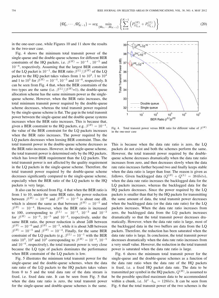
in the one-user case, while Figures 10 and 11 show the resultsin the two-user case.Fig. 4 shows the minimum total transmit power of the
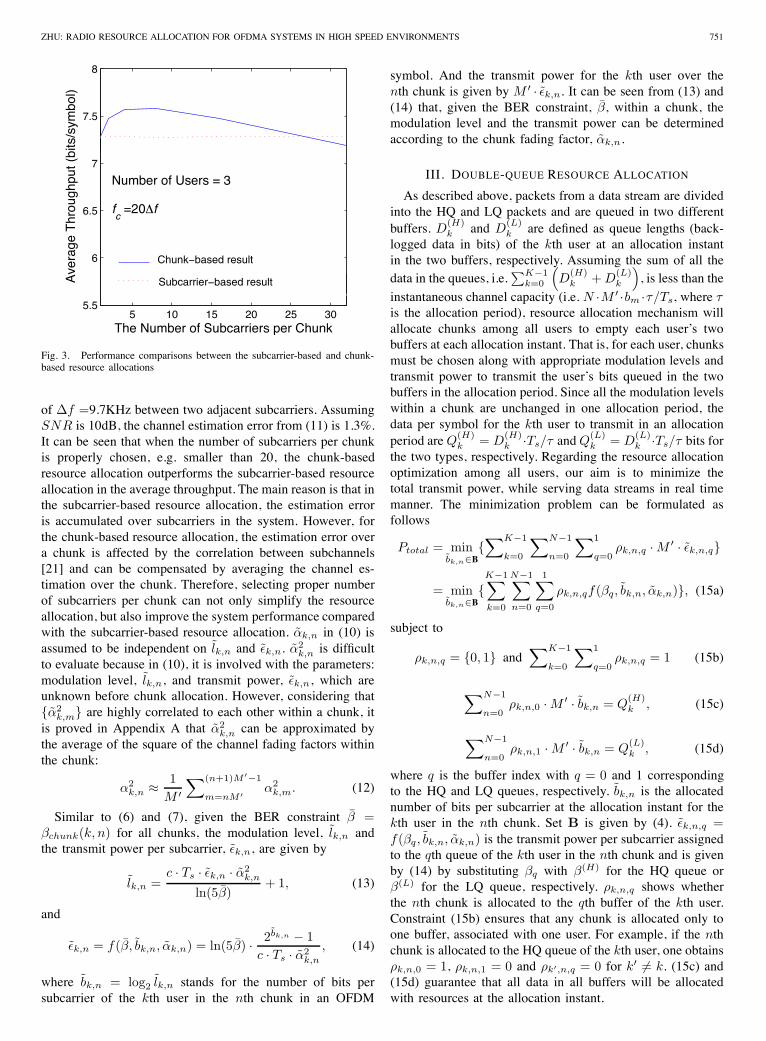
single-queue and the double-queue schemes for different BERconstraints of the HQ packets, i.e. β(H) = 10−4 , 10−5 and10−6, respectively. Assuming that the largest BER constraintof the LQ packet is 10−1, the BER ratio β(L)/β(H) of the LQpacket to the HQ packet takes values from 1 to 103, 1 to 104
and 1 to 105 for β(H) = 10−4, 10−5 and 10−6, respectively. Itcan be seen from Fig. 4 that, when the BER constraints of thetwo types are the same (i.e. β(L)/β(H)=1), the double-queueallocation scheme has the same minimum power as the single-queue scheme. However, when the BER ratio increases, thetotal minimum transmit power required by the double-queuescheme decreases, whereas the total transmit power requiredby the single-queue scheme is flat. The gap in the total transmitpower between the single-queue and the double queue systemsincreases when the BER ratio increases. This is because that,given a BER constraint to the HQ packets, e.g. β(H) = 10−4,the value of the BER constraint for the LQ packets increaseswhen the BER ratio increases. The power required by theLQ packets decreases when loosing BER constraint. Thus, thetotal transmit power in the double-queue scheme decreases asthe BER ratio increases. However, in the single-queue scheme,the total transmit power is determined only by the HQ packets,which has lower-BER requirement than the LQ packets. Thetotal transmit power is not affected by the quality requirementin the LQ packets in the single-queue scheme. Therefore, thetotal transmit power required by the double-queue schemedecreases significantly compared to the single-queue scheme,especially when the BER ratio of the LQ packets to the HQpackets is very large.It also can be noticed from Fig. 4 that when the BER ratio is
from 1 to 10, under the same BER ratio, the power reductionbetween β(H) = 10−6 and β(H) = 10−5 is about one dB,which is almost the same as that between β(H) = 10−5 andβ(H) = 10−4. However, when the BER ratio is increasedto 100, corresponding to β(L) = 10−4, 10−3 and 10−2
for β(H) = 10−6, 10−5 and 10−4, respectively, under thesame BER ratio, the power reduction is about 2dB betweenβ(H) = 10−6 and β(H) = 10−5, while it is about 3dB betweenβ(H) = 10−5 and β(H) = 10−4. Finally, for the same BERconstraint of the LQ packets (e.g. β(L) = 10−1 with the BERratio 103, 104 and 105 corresponding to β(H) = 10−4, 10−5
and 10−6, respectively), the total transmit power is very closebecause the LQ type of packets dominates the performancewhen BER constraint of the LQ packets is low.Fig. 5 illustrates the minimum total transmit power for the
single-queue and the double-queue schemes, when the datarate ratio of the LQ packets to the HQ packets takes valuesfrom 0 to 5 and the total data rate of the data stream isfixed, i.e. fixed data rate. It can be seen from Fig. 5 thatwhen the data rate ratio is zero, the total transmit powerfor the single-queue and double-queue schemes is the same.
100
101
102
103
104
105
32
33
34
35
36
37
38
39
BER Ratio β(L)/β(H)T
otal
Tra
nsm
it P
ower
(dB
)
Double queueSingle queue
β(H)=10−4
β(H)=10−6
β(H)=10−5
1
Fig. 4. Total transmit power versus BER ratio for different value of β(H)
in the one-user case
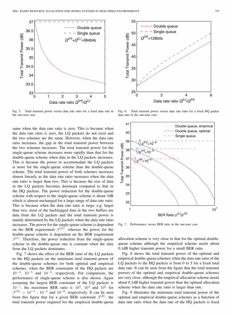
This is because when the data rate ratio is zero, the LQpackets do not exist and both the schemes perform the same.However, the total transmit power required by the double-queue scheme decreases dramatically when the data rate ratioincreases from zero, and then decreases slowly when the datarate ratio increases further beyond two and finally keeps stablewhen the data ratio is larger than four. The reason is given asfollows. Given backlogged data (Q(H) + Q(L) = 384bits),when the data rate ratio increases the backlogged data for theLQ packets increases, whereas the backlogged data for theHQ packets decreases. Since the power required by the LQpackets is smaller than that by the HQ packets for transmittingthe same amount of data, the total transmit power decreaseswhen the backlogged data (or the data rate ratio) for the LQpackets increases. When the data rate ratio increases fromzero, the backlogged data from the LQ packets increasesdramatically so that the total transmit power decreases dra-matically. However, when the data rate ratio is large, most ofthe backlogged data in the two buffers are data from the LQpackets. Therefore, the reduction has been saturated when thedata rate ratio is large. In conclusion, the total transmit powerdecreases dramatically when the data rate ratio increases froma very small value. However, the reduction in the total transmitpower is saturated when the data rate ratio is large.Fig. 6 shows the minimum total transmit power for the
single-queue and the double-queue schemes as a function ofthe data rate ratio when the data rate of the HQ packetsis fixed, i.e. a fixed HQ packet data rate. The data to betransmitted per symbol in the HQ packets,Q(H), is assumed tobe the possible specified maximum data to be accommodatedwithin a chunk, i.e. M ′ · bm = 128bits. It can be seen fromFig. 6 that the total transmit power of the two schemes is the
ZHU: RADIO RESOURCE ALLOCATION FOR OFDMA SYSTEMS IN HIGH SPEED ENVIRONMENTS 755
0 1 2 3 4 533
33.5
34
34.5
35
35.5
36
36.5
37
Data rate ratio Q(H)/Q(L)
Tot
al T
rans
mit
Pow
er (
dB)
Double queueSingle queue
Q(H)+Q(L)=384bits
Fig. 5. Total transmit power versus data rate ratio for a fixed data rate inthe one-user case
same when the data rate ratio is zero. This is because whenthe data rate ratio is zero, the LQ packets do not exist andthe two schemes are the same. However, when the data rateratio increases, the gap in the total transmit power betweenthe two schemes increases. The total transmit power for thesingle-queue scheme increases more rapidly than that for thedouble-queue scheme when data in the LQ packets increases.This is because the power to accommodate the LQ packetsis more for the single-queue scheme than the double-queuescheme. The total transmit power of both schemes increasesalmost linearly as the data rate ratio increases when the datarate ratio is larger than two. This is because the size of datain the LQ packets becomes dominant compared to that inthe HQ packets. The power reduction for the double-queuescheme with respect to the single-queue scheme is about 3dBwhich is almost unchanged for a large range of data rate ratio.This is because when the data rate ratio is large, e.g. largerthan two, most of the backlogged data in the two buffers aredata from the LQ packets and the total transmit power ismainly determined by the LQ packets when the data rate ratioincreases. The power for the single-queue scheme is dependenton the BER requirement β(H), whereas the power for thedouble-queue scheme is dependent on the BER requirementβ(L). Therefore, the power reduction from the single-queuescheme to the double-queue one is constant when the datafrom the LQ packets dominates.Fig. 7 shows the effect of the BER ratio of the LQ packets
to the HQ packets on the minimum total transmit power ofthe double-queue schemes for both optimal and empiricalschemes, when the BER constraints of the HQ packets are10−4, 10−5 and 10−6, respectively. For comparison, theperformance of single-queue scheme is also shown. Againassuming the largest BER constraint of the LQ packets is10−1, the maximum BER ratio is 103, 104 and 105 forβ(H) = 10−4 , 10−5 and 10−6, respectively. It can be seenfrom this figure that for a given BER constraint β(H), thetotal transmit power required for the empirical double-queue
0 2 4 625
30
35
40
45
50
55
Data rate ratio Q(L)/Q(H)
Tot
al T
rans
mit
Pow
er (
dB)
Double queueSingle queue
Q(H)=128bits
Fig. 6. Total transmit power versus data rate ratio for a fixed HQ packetdata rate in the one-user case
100
105
32
33
34
35
36
37
38
39
40
41
BER Ratio β(L)/β(H)
Tot
al T
rans
mit
Pow
er (
dB)
Double queue, empiricalDouble queue, optimalSingle queue
β(H)=10−4
β(H)=10−5
β(H)=10−6
1
Fig. 7. Performance versus BER ratio in the one-user case
allocation scheme is very close to that for the optimal double-queue scheme although the empirical scheme needs about0.1dB higher transmit power for a small BER ratio.Fig. 8 shows the total transmit power of the optimal and
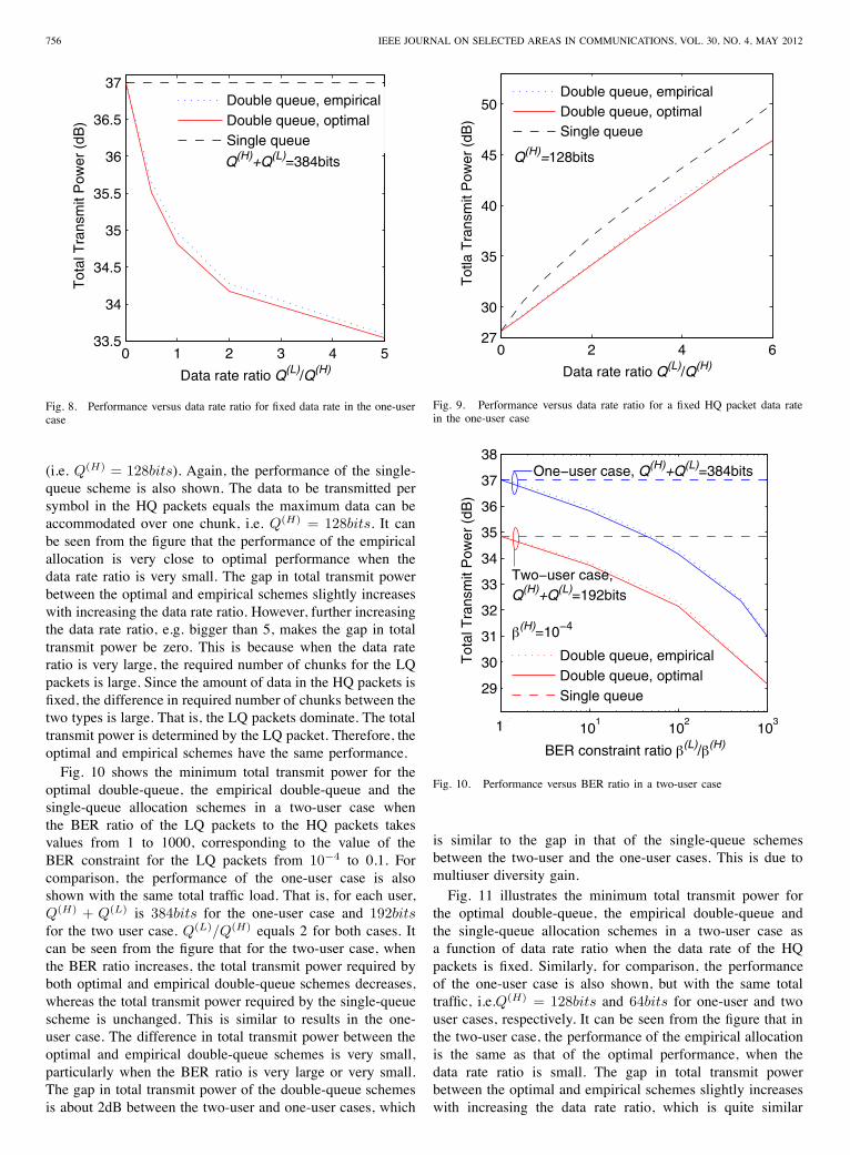
empirical double-queue schemes when the data rate ratio of theLQ packets to the HQ packets is from 0 to 5 for a fixed totaldata rate. It can be seen from the figure that the total transmitpowers of the optimal and empirical double-queue schemesare very close, although the empirical allocation scheme needsabout 0.1dB higher transmit power than the optimal allocationscheme when the data rate ratio is larger than one.Fig. 9 illustrates the minimum total transmit power of the
optimal and empirical double-queue schemes as a function ofdata rate ratio when the data rate of the HQ packets is fixed
756 IEEE JOURNAL ON SELECTED AREAS IN COMMUNICATIONS, VOL. 30, NO. 4, MAY 2012
0 1 2 3 4 533.5
34
34.5
35
35.5
36
36.5
37
Data rate ratio Q(L)/Q(H)
Tot
al T
rans
mit
Pow
er (
dB)
Double queue, empiricalDouble queue, optimalSingle queue
Q(H)+Q(L)=384bits
Fig. 8. Performance versus data rate ratio for fixed data rate in the one-usercase
(i.e. Q(H) = 128bits). Again, the performance of the single-queue scheme is also shown. The data to be transmitted persymbol in the HQ packets equals the maximum data can beaccommodated over one chunk, i.e. Q(H) = 128bits. It canbe seen from the figure that the performance of the empiricalallocation is very close to optimal performance when thedata rate ratio is very small. The gap in total transmit powerbetween the optimal and empirical schemes slightly increaseswith increasing the data rate ratio. However, further increasingthe data rate ratio, e.g. bigger than 5, makes the gap in totaltransmit power be zero. This is because when the data rateratio is very large, the required number of chunks for the LQpackets is large. Since the amount of data in the HQ packets isfixed, the difference in required number of chunks between thetwo types is large. That is, the LQ packets dominate. The totaltransmit power is determined by the LQ packet. Therefore, theoptimal and empirical schemes have the same performance.Fig. 10 shows the minimum total transmit power for the
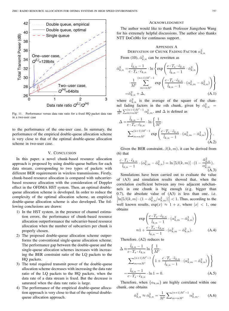
optimal double-queue, the empirical double-queue and thesingle-queue allocation schemes in a two-user case whenthe BER ratio of the LQ packets to the HQ packets takesvalues from 1 to 1000, corresponding to the value of theBER constraint for the LQ packets from 10−4 to 0.1. Forcomparison, the performance of the one-user case is alsoshown with the same total traffic load. That is, for each user,Q(H) + Q(L) is 384bits for the one-user case and 192bitsfor the two user case. Q(L)/Q(H) equals 2 for both cases. Itcan be seen from the figure that for the two-user case, whenthe BER ratio increases, the total transmit power required byboth optimal and empirical double-queue schemes decreases,whereas the total transmit power required by the single-queuescheme is unchanged. This is similar to results in the one-user case. The difference in total transmit power between theoptimal and empirical double-queue schemes is very small,particularly when the BER ratio is very large or very small.The gap in total transmit power of the double-queue schemesis about 2dB between the two-user and one-user cases, which
0 2 4 627
30
35
40
45
50
Data rate ratio Q(L)/Q(H)
Tot
la T
rans
mit
Pow
er (
dB)
Double queue, empiricalDouble queue, optimalSingle queue
Q(H)=128bits
Fig. 9. Performance versus data rate ratio for a fixed HQ packet data ratein the one-user case
100
101
102
103
29
30
31
32
33
34
35
36
37
38
BER constraint ratio β(L)/β(H)
Tot
al T
rans
mit
Pow
er (
dB)
Double queue, empiricalDouble queue, optimalSingle queue
Two−user case,Q(H)+Q(L)=192bits
One−user case, Q(H)+Q(L)=384bits
β(H)=10−4
1
Fig. 10. Performance versus BER ratio in a two-user case
is similar to the gap in that of the single-queue schemesbetween the two-user and the one-user cases. This is due tomultiuser diversity gain.Fig. 11 illustrates the minimum total transmit power for
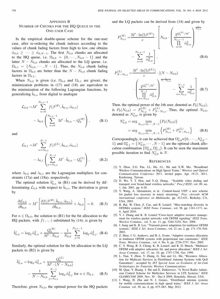
the optimal double-queue, the empirical double-queue andthe single-queue allocation schemes in a two-user case asa function of data rate ratio when the data rate of the HQpackets is fixed. Similarly, for comparison, the performanceof the one-user case is also shown, but with the same totaltraffic, i.e.Q(H) = 128bits and 64bits for one-user and twouser cases, respectively. It can be seen from the figure that inthe two-user case, the performance of the empirical allocationis the same as that of the optimal performance, when thedata rate ratio is small. The gap in total transmit powerbetween the optimal and empirical schemes slightly increaseswith increasing the data rate ratio, which is quite similar
ZHU: RADIO RESOURCE ALLOCATION FOR OFDMA SYSTEMS IN HIGH SPEED ENVIRONMENTS 757
0 1 2 326
28
30
32
34
36
38
40
42
Data rate ratio Q(L)/Q(H)
Tot
al T
rans
mit
Pow
er (
dB)
Double queue, empiricalDouble queue, optimalSingle queue
One−user case,Q(L)=128bits
Two−user case,Q(H)=64bits
Fig. 11. Performance versus data rate ratio for a fixed HQ packet data ratein a two-user case
to the performance of the one-user case. In summary, theperformance of the empirical double-queue allocation schemeis very close to that of the optimal double-queue allocationscheme in two-user case.
V. CONCLUSION
In this paper, a novel chunk-based resource allocationapproach is proposed by using double-queue buffers for eachdata stream, corresponding to two types of packets withdifferent BER requirements in wireless transmissions. Firstly,chunk-based resource allocation is compared with subcarrier-based resource allocation with the consideration of Dopplereffect in the OFDMA HST system. Then, an optimal double-queue allocation scheme is developed. In order to reduce thecomplexity of the optimal allocation scheme, an empiricaldouble-queue allocation scheme is also developed. The fol-lowing conclusions are drawn:1) In the HST system, in the presence of channel estima-tion errors, the performance of chunk-based resourceallocation outperformance the subcarrier-based resourceallocation when the number of subcarriers per chunk isproperly chosen.
2) The proposed double-queue allocation scheme outper-forms the conventional single-queue allocation scheme.The performance gap between the double-queue and thesingle-queue allocation schemes increases with increas-ing the BER constraint ratio of the LQ packets to theHQ packets.
3) The total required transmit power of the double-queueallocation scheme decreases with increasing the data rateratio of the LQ packets to the HQ packets, when thedata rate of a data stream is fixed. But the decrease issaturated when the data rate ratio is large.
4) The performance of the empirical double-queue alloca-tion approach is very close to that of the optimal double-queue allocation approach.
ACKNOWLEDGMENT
The author would like to thank Professor Jiangzhou Wangfor his extremely helpful discussions. The author also thanksNTT DoCoMo for continuous support.
APPENDIX ADERIVATION OF CHUNK FADING FACTOR α2
k,n
From (10), α2k,n can be rewritten as
α2k,n =
lk,n − 1c · Ts · εk,n
· ln{exp
(c · Ts · εk,n
lk,n − 1· α2
k,n
)
· 1M ′
(n+1)M ′−1∑m=nM ′
exp
(c · Ts · εk,n
lk,n − 1· (α2
k,m − α2k,n)
)⎫⎬⎭
=α2k,n + Δ, (A.1)
where α2k,n is the average of the square of the chan-
nel fading factors in the nth chunk, given by α2k,n =
1M ′∑(n+1)M ′−1
m=nM ′ α2k,m, and Δ is defined as
Δ =lk,n − 1
c · Ts · εk,n· ln{
1M ′ ·
∑(n+1)M ′−1
m=nM ′ exp
(c · Ts · εk,n
lk,n − 1· (α2
k,m − α2k,n)
)}.
(A.2)
Given the BER constraint, β(k, m), it can be derived from(6) that
c · Ts · εk,n
lk,n − 1· (α2
k,m − α2k,n) = ln [5β(k, m)] · (1 − α2
k,n
α2k,m
).
(A.3)Simulations have been carried out to evaluate the value
of (A3) and simulation results showed that, when thecorrelation coefficient between any two adjacent subchan-nels in one chunk is big enough (e.g. bigger than0.7), the absolute value of (A3) is less than one, i.e.∣∣∣ln[5β(k, m) · (1 − α2
k,n/α2k,m)]
∣∣∣ < 1. Thus, according to thewell known results, exp(x) ≈ 1 + x, where |x| < 1, oneobtains
exp
(c · Ts · εk,n
lk,n − 1· (α2
k,m − α2k,n)
)
≈1 +c · Ts · εk,n
lk,n − 1· (α2
k,m − α2k,n). (A.4)
Therefore, (A2) reduces to
Δ ≈ lk,n − 1c · Ts · εk,n
ln{
1M ′ ·
∑(n+1)M ′−1
m=nM ′
(1 +
c · Ts · εk,n
lk,n − 1· (α2
k,m − α2k,n)
)}
=lk,n − 1
c · Ts · εk,n· ln 1 = 0. (A.5)
Therefore, when {αk,m} are highly correlated within onechunk, one obtains
α2k,n ≈ α2
k,n =1
M ′∑(n+1)M ′−1
m=nM ′ α2k,m. (A.6)
758 IEEE JOURNAL ON SELECTED AREAS IN COMMUNICATIONS, VOL. 30, NO. 4, MAY 2012
APPENDIX BNUMBER OF CHUNKS FOR THE HQ QUEUE IN THE
ONE-USER CASE
In the empirical double-queue scheme for the one-usercase, after re-ordering the chunk indexes according to thevalues of chunk fading factors from high to low, one obtainsα0,0 ≥ · · · ≥ α0,N−1. The first N0,0 chunks are allocatedto the HQ queue, i.e. Ω0,0 = {0, · · · , N0,0 − 1} and thelatter N − N0,0 chunks are allocated to the LQ queue, i.e.Ω0,1 = {N0,0, · · · , N − 1}. Thus, the N0,0 chunk fadingfactors in Ω0,0 are better than the N − N0,0 chunk fadingfactors in Ω0,1.When N0,0 is given (i.e. Ω0,0 and Ω0,1 are given), the
minimization problems in (17) and (18) are equivalent tothe minimization of the following Lagrangian functions, bygeneralizing b0,n from digital to analogue
L0,0 =M ′N0,0−1∑
n=0
f(β(H), b0,n, α0,n)
− λ0,0
⎛⎝N0,0−1∑
n=0
M ′ · b0,n − Q(H)0
⎞⎠ , (B.1)
and
L0,1 =M ′N−1∑
n=N0,0
f(β(L), b0,n, α0,n)
− λ0,1
⎛⎝ N−1∑
n=N0,0
M ′ · b0,n − Q(L)0
⎞⎠ , (B.2)
where λ0,0 and λ0,1 are the Lagrangian multipliers for con-straints (17a) and (18a), respectively.The optimal solution b∗0,n in (B1) can be derived by dif-
ferentiating L0,0 with respect to b0,n. The derivation is givenby
∂L0,0
∂b0,0
= M ′[
∂f(β(H), b0,n, α0,n)∂b0,n
+ λ0,0
]= 0. (B.3)
For n ∈ Ω0,0, the solution to (B1) for the bit allocation to theHQ packets, with f(·, ·, ·) substituted by (14), is given by
b∗0,n = log2 α20,n +
Q(H)0
M ′ · N0,0− 1
N0,0
N0,0−1∑j=0
log2 α20,j . (B.4)
Similarly, the optimal solution for the bit allocation to the LQpackets to (B2) is given by
b∗0,n = log2 α20,n +
Q(L)0
M ′ · (N − N0,0)
− 1N − N0,0
N−1∑j=N0,0
log2 α20,j for n ∈ Ω0,1. (B.5)
Therefore, given N0,0, the optimal power for the HQ packets
and the LQ packets can be derived from (14) and given by
P(H)N0,0
=M ′ · ln(5β(H))
c·
⎡⎢⎢⎢⎢⎣N0,0 ·
⎛⎜⎜⎜⎝ 2Q
(H)0 /M ′
N0,0−1∏n=0
α20,n
⎞⎟⎟⎟⎠
1N0,0
−N0,0−1∑
n=0
1α2
0,n
⎤⎦ , (B.6)
P(L)N−N0,0
=M ′ · ln(5β(L))
c· [(N − N0,0)
·
⎛⎜⎜⎜⎝ 2Q
(L)0 /M ′
N−1∏n=N0,0
α20,n
⎞⎟⎟⎟⎠
1N−N0,0
−N−1∑
n=N0,0
1α2
0,n
⎤⎥⎥⎥⎥⎦ (B.7)
Then, the optimal power of the kth user, denoted as P0(N0,0),is P0(N0,0) = P
(H)N0,0
+ P(L)N−N0,0
. Thus, the optimal N0,0,denoted as N∗
0,0, is given by
N∗0,0 = arg min
N0,0=0,··· ,N−1{P0(N0,0)}
= arg minN0,0=0,··· ,N−1
{P
(H)N0,0
+ P(L)N−N0,0
}(B.8)
Correspondingly, it can be achieved that Ω∗0,0={0, · · · , N∗
0,0−1} and Ω∗
0,1 = {N∗0,0, · · · , N −1} are the optimal chunk allo-
cation combination {Ω∗0,0, Ω
∗0,1}. It can be seen the maximum
possible iteration to find N∗0,0 is N .
REFERENCES
[1] Y. Zhou, Z.G. Pan, J.L. Hu, J.L. Shi and X.W. Mo, “BroadbandWireless Communications on High Speed Trains,” Wireless and OpticalCommunication Conference 2011, invited paper, Apr. 19-21, 2011,Kaohsiung, Taiwan.
[2] D. Wu, Y. T. Hou, and Y.-Q. Zhang, “Scalable video doding andtransport over broad-band wireless networks,” Proc.f IEEE, vol. 89, no.1, Jan. 2001, pp. 6-20.
[3] Y. Wang, A. Ahmaniemi, et al, Content-based UEP: a new schemefor packet loss recovery in music streaming,” Proc. eleventh ACMinternational conference on Multimedia, pp. 412-421, Berkeley, CA,USA, 2003.
[4] B. Bai, W. Chen, Z. Cao, and B. Letaief, “Max-matching diversity inOFDMA systems,” IEEE Trans. Commun., vol. 58, pp. 1161-1171, no.4, April 2010.
[5] Y. J. Zhang and K. B. Letaief,“Cross-layer adaptive resource manage-ment for wireless packet networks with OFDM signaling” IEEE Trans.Wireless Commun., vol. 5, no. 11, pp. 3244-3254, Nov. 2006.
[6] J. Jiang and K. B. Lee, “Transmit power adaptation for multiuser OFDMsystems,” IEEE J. Sel. Areas Commun., vol. 21, no. 2, pp. 171-178, Feb.2003.
[7] Z. Shen, J. G. Andrews, and B. L. Evans, “Adaptive resource allocationin multiuser OFDM systems with proportional rate constraints,” IEEETrans. Wireless Commun., vol. 4, No. 6, pp. 2726-2737, Nov. 2005.
[8] C. Y. Wong, R. S. Cheng, K. B. Letaief, and R. D. Murch, “MultiuserOFDM with adaptive subcarrier, bit, and power allocation,” IEEE J. Sel.Areas Commun., vol. 17, no. 10, pp. 1747-1758, Oct. 1999.
[9] L. Tian, Y. Zhou, Y. Zhang, G. Sun and J.L. Shi, “Resource Alloca-tion for Multicast Services in Distributed Antenna Systems with QoSGuarantees”, accepted by IET Special Issue on Evolution of Air-LinkTechnologies for Futuristic Wireless Communications.
[10] M. Qian, Y. Huang, J. Shi and E. Dutkiewicz, “A Novel Radio Admis-sion Control Scheme for Multiclass Services in LTE Systems,” IEEEGLOBECOM 2009, Nov. 30 - Dec.4 2009, Honolulu, Hawaii, USA.
[11] J. Wang, H. Zhu and N. J. Gomes, “Distributed antenna systemsfor mobile communications in high speed trains,” IEEE J. Sel. AreasCommun. vol. 30, no. 4, pp. 675–683, May 2012.
ZHU: RADIO RESOURCE ALLOCATION FOR OFDMA SYSTEMS IN HIGH SPEED ENVIRONMENTS 759
[12] J. Wang and L. B. Milstein, “CDMA overlay situations for microcellularmobile communications,” IEEE Trans. Commun., vol. 43, no. 2/3/4, pp.603-614, Feb./Mar./April 1995.
[13] J. Wang and J. Chen, “Performance of wideband CDMA with com-plex spreading and imperfect channel estimation,” IEEE J. Sel. AreasCommun., vol. 19, no. 1, pp. 152-163, Jan. 2001.
[14] H. Zhu and J. Wang, “Chunk-based resource allocation in OFDMAsystems - Part I: chunk allocation,” IEEE Trans. Commun., vol. 57, no.9, pp. 2734-2744, Sept. 2009.
[15] H. Zhu and J. Wang, “Chunk-based resource allocation in OFDMAsystems - Part II: Joint power, chunk and bit allocation,” IEEE Trans.Commun., vol. 60, no. 2, pp. 499–509, Feb. 2012.
[16] H. Zhu, “Performance comparison between microcellular and distributedantenna systems,” IEEE J. Sel. Areas Commun., vol. 29, no. 6, pp. 1151-1163, June 2011.
[17] Y. Zhou and J. Wang, “Downlink transmission of broadband OFCDMsystems - part IV: soft decision,” IEEE J. Sel. Areas Commun., vol. 24,no. 6, pp.1208-1220, June 2006.
[18] S. T. Chung and A. J. Goldsmith, “Degrees of freedom in adaptivemodulation: a unified view”, IEEE Trans.Commun., vol.49, no. 9, pp.1561-1571, Sept. 2001.
[19] M. A. R. Baissas and A. M. Sayeed, “Pilot-based channel estimation fortime-varying multipath channels for coherent CDMA receivers,” IEEETrans. Signal Process., vol. 50, no. 8, pp. 2037-2049, Aug. 2002.
[20] D. Piazza and L. B. Milstein, “Analysis of multiuser diversity in time-
varying channels,” IEEE Trans. Wireless Commun., vol. 6, no. 12, pp.4412-4419, Dec. 2007.
[21] Y. Q. Zhou, J. Wang and M. Sawahashi, “Downlink transmission ofbroadband OFCDM systems – Part II: effect of Doppler shift,” IEEETrans. Commun., vol. 54, pp. 1097-1108, June 2006.
Huiling Zhu (M’04) received the B.S degree fromXidian Univeristy, Xi’an, China, in 1997, and thePh.D. degree from Tsinghua University, Beijing,China in 2003. She is currently a Research Associatewith the School of Engineering and Digital Arts,University of Kent, Canterbury, United Kingdom.Her research interests are in the area of broadbandwireless mobile communications, covering topicssuch as radio resource allocation and management,MIMO, OFDMA, cooperative communications, anddistributed antenna systems. She has received the
best paper award in IEEE Globecom 2011. She has participated in a number ofEuropean and industrial projects in these topics. She is the Publication Chairof IEEE WCNC2013 and the Local Arrangement Chair of IEEE ICC2015.