radiocommunication systems - isip40 · radiocommunication systems data transmission by ......
TRANSCRIPT
1
RADIOCOMMUNICATIONSYSTEMS
DATA TRANSMISSION BY ORTHOGONAL
FREQUENCY DIVIVSION MULTIPLEXING MODULATION
Prof. C. Regazzoni
2
References
[1] M.L. Doelz, E.T. Heald, D. Martin, “Binary Data Transmission Techniques forLinear Systems”, Proceedings of IRE, Maggio 1957, pp. 656-661.
[2] B. Hirosaki, “An Orthogonally Multiplexed QAM System Using the Discrete FourierTransform”, IEEE Trans on Comm, Vol. 29, No. 7, Luglio 1981, pp. 982-989.
[3] J.A.C. Bingham, “Multicarrier Modulation for Data Transmission: An Idea WhoseTime Has Come”, IEEE Comm. Magazine, Maggio 1990, pp. 5- 14.
[4] T. De Cousanon, R. Monnier, J.B. Rault, “OFDM for digital TV broadcasting”; SignalProcessing, Vol. 39 (1994), pp. 1-32.
[5] B. Le Floch, M. Alard, C. Berrou, “Coded Orthogonal Frequency Division Multiplex”,Proceedings of IEEE, Vol. 83, No.6, Giugno 1995, pp. 982-996.
[6] E. Ayanoglu, et al, “VOFDM Broadband Wireless Transmission and ItsAdvantages over Single Carrier Modulation”, Proc of ICC 2001 Conference, Helsinki(SF) 11-14 Giugno 2001, Vol. 6, pp. 1660- 1664.
3
Introduction
The OFDM modulation (Orthogonal Frequency Division Multiplexing) is thebasic technique among the multi-carrier modulations a clear example of multi-carrier modulation is the DMT that is employed in the ADSL standard fortransmissions on twisted pair with high bit-rate.
Another example is comprised by the MC-CDMA techniques (Multi-carrierCDMA) which are the spread-spectrum version of the OFDM modulation.
The basic concept of multi-carrier modulation is the transmission in diversity,i.e. the transmission of information on sub-channels with different bandwidth,where the distortion effects of the channel are different.
As contrary to the single-carrier techniques, transmitted message will suffer, ina different measure, of the frequency selective effects of the channel. But asubstantial improvement of performances in terms of BER is possible.
4
Historical Mentions
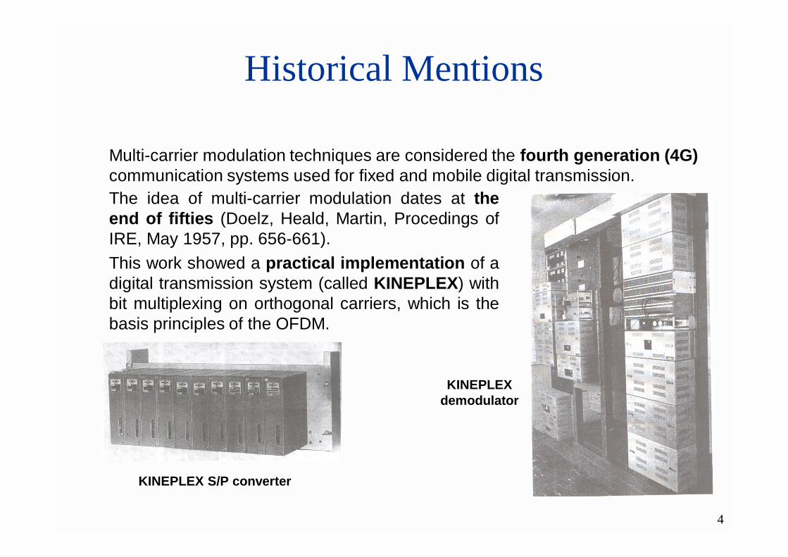
Multi-carrier modulation techniques are considered the fourth generation (4G)communication systems used for fixed and mobile digital transmission.The idea of multi-carrier modulation dates at theend of fifties (Doelz, Heald, Martin, Procedings ofIRE, May 1957, pp. 656-661).This work showed a practical implementation of adigital transmission system (called KINEPLEX) withbit multiplexing on orthogonal carriers, which is thebasis principles of the OFDM.
KINEPLEX S/P converter
KINEPLEX demodulator
5
Historical Mentions
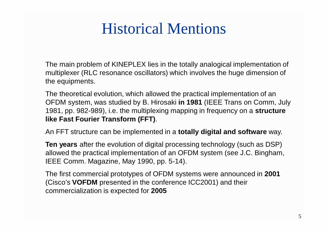
The main problem of KINEPLEX lies in the totally analogical implementation of multiplexer (RLC resonance oscillators) which involves the huge dimension of the equipments.
The theoretical evolution, which allowed the practical implementation of an OFDM system, was studied by B. Hirosaki in 1981 (IEEE Trans on Comm, July 1981, pp. 982-989), i.e. the multiplexing mapping in frequency on a structure like Fast Fourier Transform (FFT).
An FFT structure can be implemented in a totally digital and software way.
Ten years after the evolution of digital processing technology (such as DSP) allowed the practical implementation of an OFDM system (see J.C. Bingham, IEEE Comm. Magazine, May 1990, pp. 5-14).
The first commercial prototypes of OFDM systems were announced in 2001(Cisco’s VOFDM presented in the conference ICC2001) and their commercialization is expected for 2005
6
OFDM Modulation: Introduction
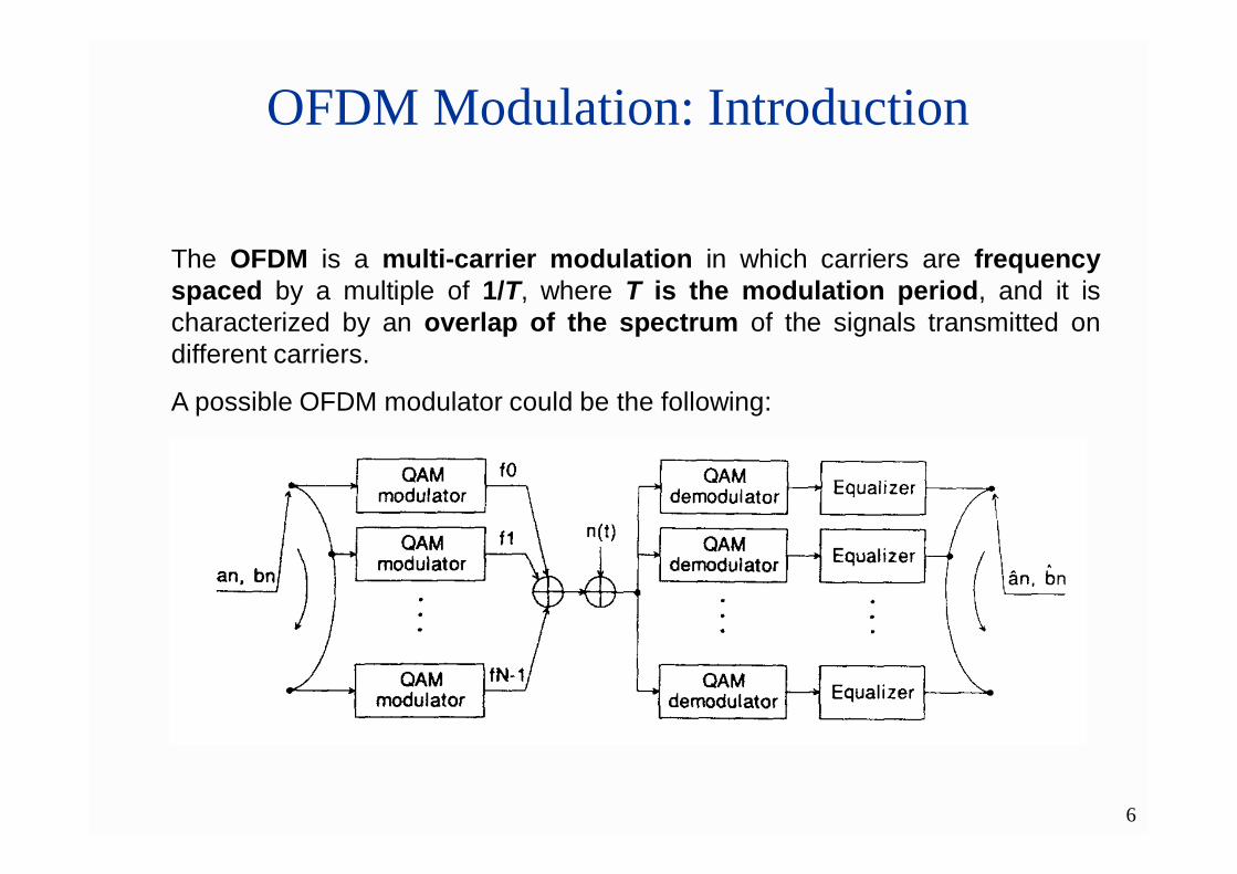
The OFDM is a multi-carrier modulation in which carriers are frequencyspaced by a multiple of 1/T, where T is the modulation period, and it ischaracterized by an overlap of the spectrum of the signals transmitted ondifferent carriers.
A possible OFDM modulator could be the following:
7
OFDM Modulation: Introduction
The previous figure shows a symbol stream, codified in-phase and in-
quadrature components (an , bn) is cyclically multiplexed on N branches
containing a QAM digital modulator.
The output of the k-th modulation branch is an M-QAM signal, modulated on
carrier frequency fk which is orthogonal to each other.
In this way it is possible, at the receiver, to recover the symbol streams
transmitted in every branch and to rebuild, after a de-multiplexing operation,
the original symbol stream.
8
OFDM Modulation: Transmitted Signal
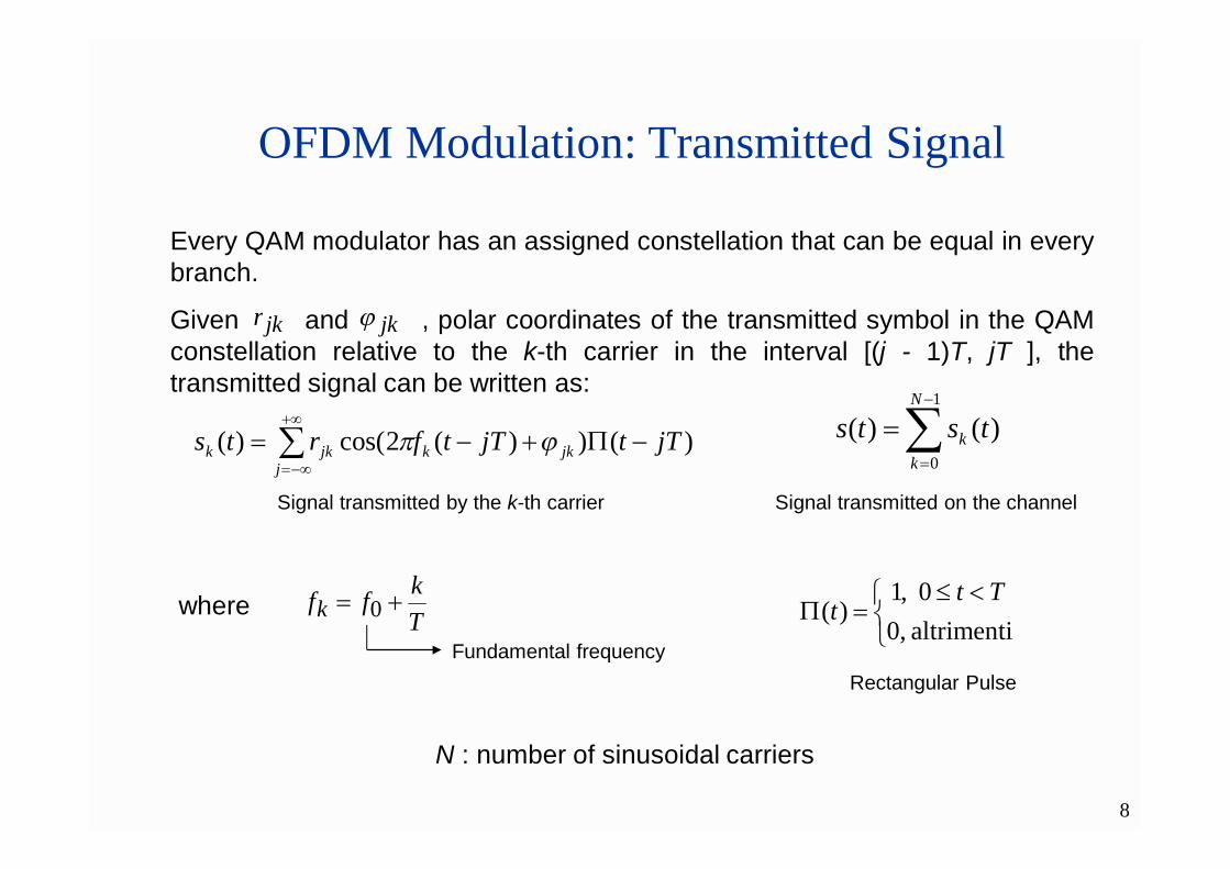
Every QAM modulator has an assigned constellation that can be equal in everybranch.
Given and , polar coordinates of the transmitted symbol in the QAMconstellation relative to the k-th carrier in the interval [(j - 1)T, jT ], thetransmitted signal can be written as:
jkr jk
jjkkjkk jTtjTtfrts )())(2cos()(
Tkffk 0
altrimenti ,00 ,1
)(Tt
t
1
0
)()(N
kk tsts
Signal transmitted by the k-th carrier Signal transmitted on the channel
where
Fundamental frequencyRectangular Pulse
N : number of sinusoidal carriers

9
OFDM Modulation: Transmitted Signal
The signal transmitted on the channel is a summation of a huge number of sinusoidal carriers, modulated with arbitrary phase and amplitude.
The result, in the time domain, is a noise-like signal:

10
OFDM Modulation: Transmitted Signal
The duration T of an OFDM modulation impulse is fixed and it’s equal to:
sNTDNaT
where
•D is the source bit-rate;
•a is the number of bit for each transmitted symbol;
•Ts is the duration time of a symbol ( N multiplexedsymbols are transmitted in the duration time of anOFDM modulation pulse);
11
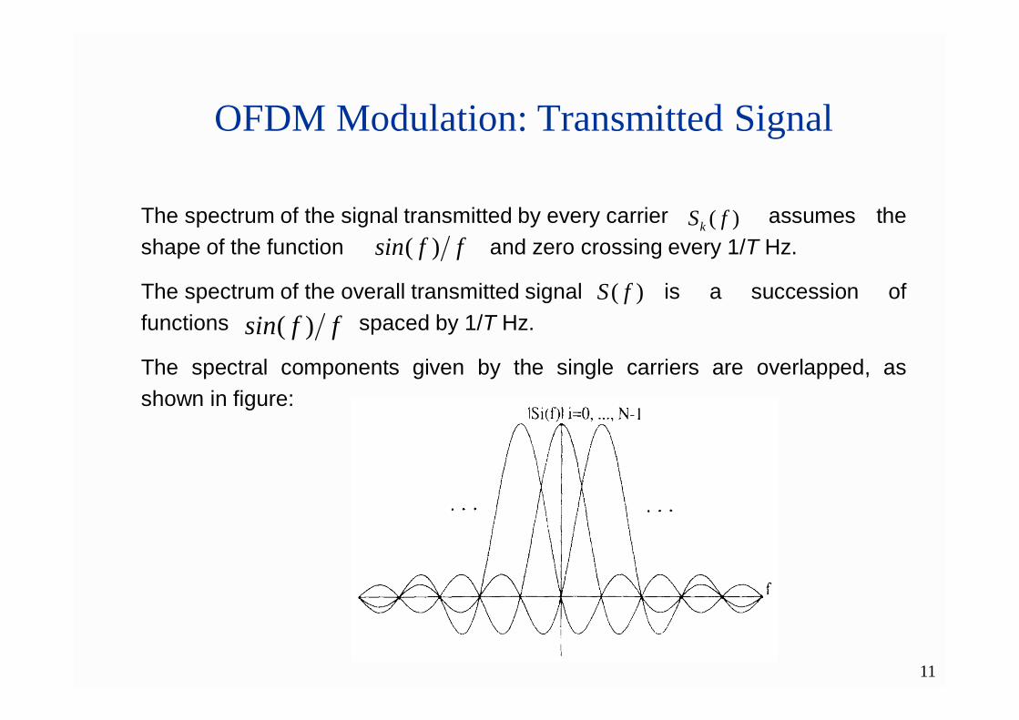
The spectrum of the signal transmitted by every carrier assumes theshape of the function and zero crossing every 1/T Hz.
The spectrum of the overall transmitted signal is a succession offunctions spaced by 1/T Hz.
The spectral components given by the single carriers are overlapped, asshown in figure:
OFDM Modulation: Transmitted Signal
)( fSffsin )(
)( fSk
ffsin )(

12
OFDM Modulation: Bandwidth Occupation
The spectrum of the OFDM signal has theoretically unlimited bandwidth.But it needs a truncation to compute the significant bandwidth occupied by thesignal.
The truncation is performed to remove all the components of the powerspectrum which are at least 20 dB under the amplitude of main lobe.
In this case only two side lobes are conserved, as shown in the followingfigure:
13
OFDM Modulation: Bandwidth Occupation
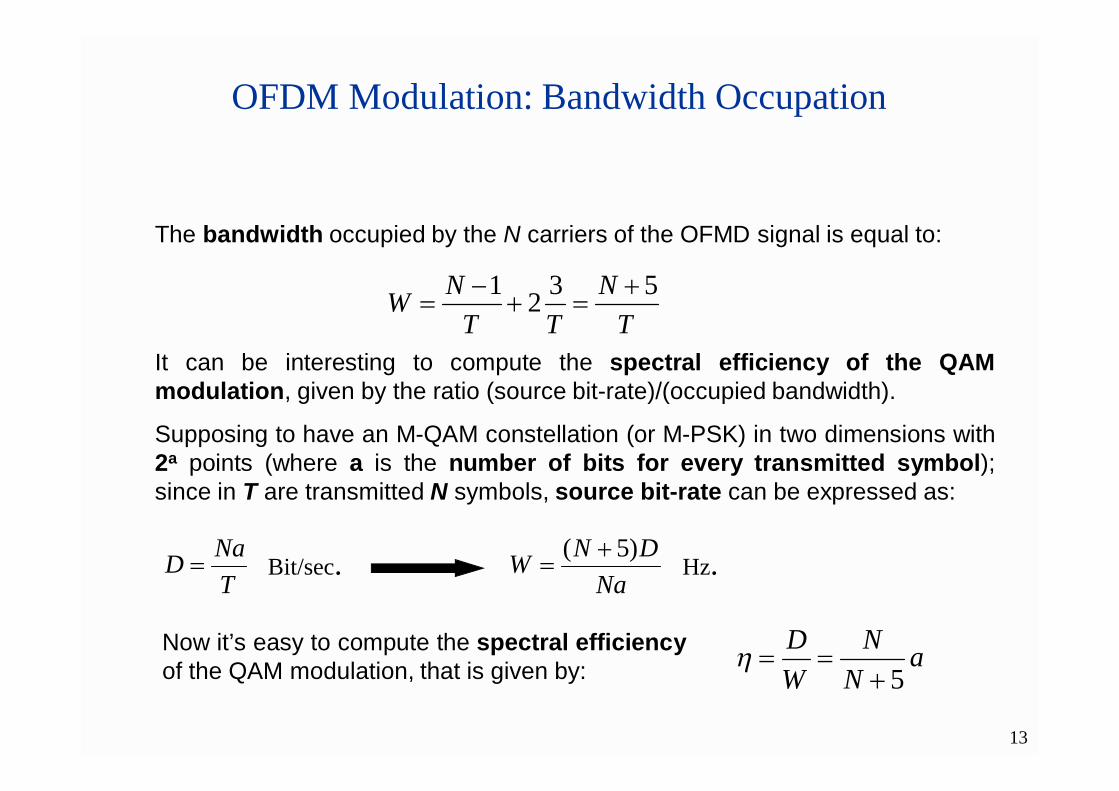
The bandwidth occupied by the N carriers of the OFMD signal is equal to:
TN
TTNW 5321
It can be interesting to compute the spectral efficiency of the QAMmodulation, given by the ratio (source bit-rate)/(occupied bandwidth).
Supposing to have an M-QAM constellation (or M-PSK) in two dimensions with2a points (where a is the number of bits for every transmitted symbol);since in T are transmitted N symbols, source bit-rate can be expressed as:
TNaD
NaDNW )5(
aN
NWD
5
Bit/sec. Hz.
Now it’s easy to compute the spectral efficiencyof the QAM modulation, that is given by:
14
OFDM Modulation: Bandwidth Occupation
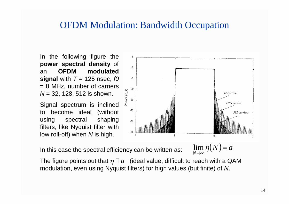
In the following figure thepower spectral density ofan OFDM modulatedsignal with T = 125 nsec, f0= 8 MHz, number of carriersN = 32, 128, 512 is shown.
Signal spectrum is inclinedto become ideal (withoutusing spectral shapingfilters, like Nyquist filter withlow roll-off) when N is high.
In this case the spectral efficiency can be written as:
The figure points out that (ideal value, difficult to reach with a QAM modulation, even using Nyquist filters) for high values (but finite) of N.
aNN
lim
a �
15
OFDM Demodulation
Modulator Demodulator
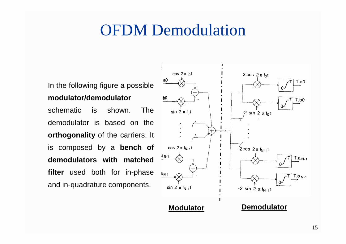
In the following figure a possible
modulator/demodulatorschematic is shown. The
demodulator is based on the
orthogonality of the carriers. It
is composed by a bench ofdemodulators with matchedfilter used both for in-phase
and in-quadrature components.

16
OFDM Demodulation
These orthogonality conditions on the carriers, both for in-phase and in-quadrature components, allow to demodulate the signal, as pointed out in the following formulas:
h k t)dtf()tf(rT
hkkk 02cos2cos0
h kaT) (rTkkk
2cos
2
h k t)dtf)sin(tf(rT
hkkk 022cos0
h kbT) sin(rTkkk
22
To have a correct demodulationprocess, other two conditions,which are considered guaranteedfor simplicity, are necessary:
• strict synchronization on thecarrier (coherentdemodulation);
• strict synchronization of theclock on the receiver side(clock recovery)
17
OFDM Modulation
A modulation/demodulation schematic, such as the previous one, cannot beimplemented via hardware with analog oscillators: it would be too muchexpensive and the imperfections of the oscillators (frequency drift, phase noise)would cause critical malfunctions.
But it can easily implemented via software, in a totally digital way, using theFFT (Fast Fourier Transform).
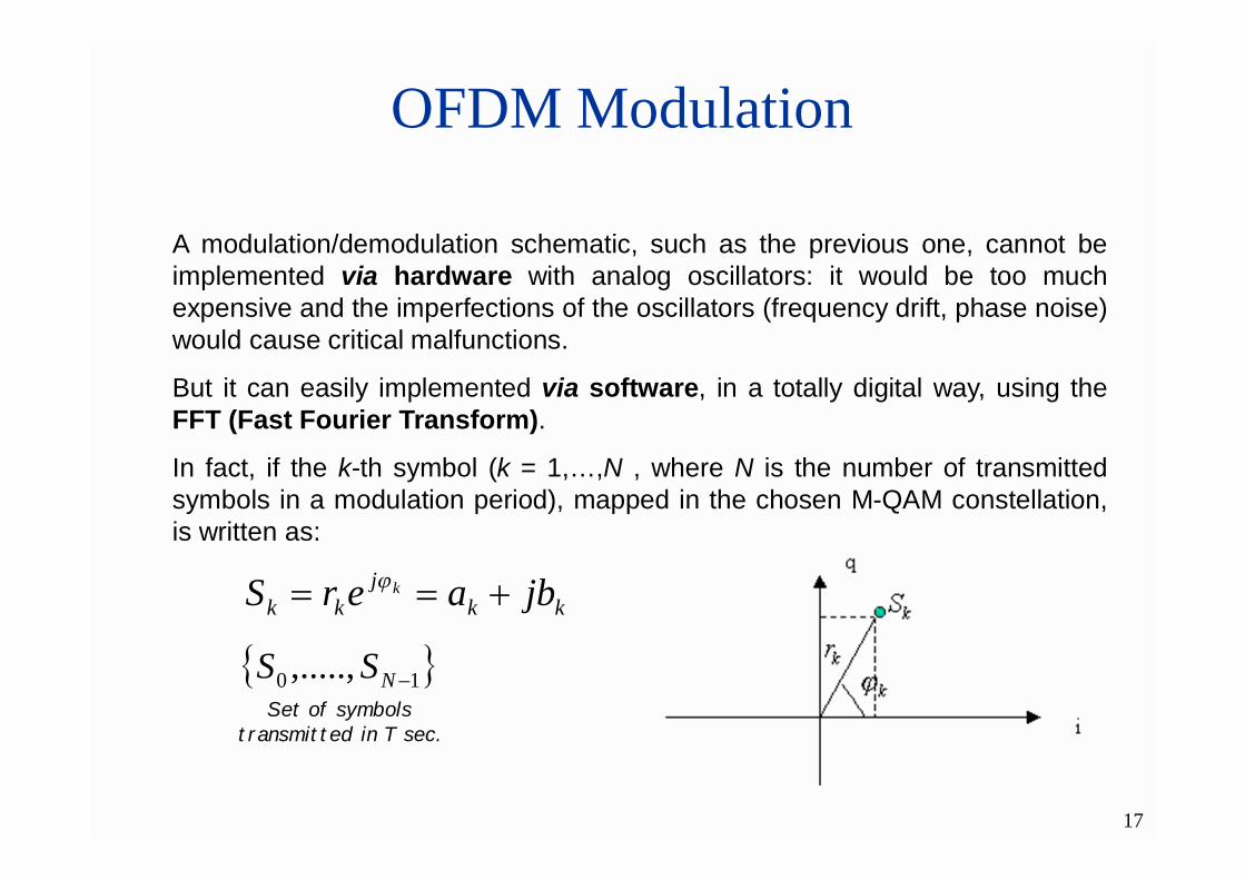
In fact, if the k-th symbol (k = 1,…,N , where N is the number of transmittedsymbols in a modulation period), mapped in the chosen M-QAM constellation,is written as:
kkj
kk jbaerS k
10 ,....., NSSSet of symbols
transmitted in T sec.
18
OFDM Modulation
The OFDM signal transmitted on the channel can be obtained by the following
steps:
1. computing the Inverse FFT (IFFT) on a set of symbols transmitted in a
modulation period T
2. performing the digital-to-analog conversion (D/A) of the signal
obtained in the previous step.
In fact a sequence s(n) is generated by using an IFFT operation performedon the set of symbols transmitted in the modulation period T, with a number ofsamples NFFT (generally it is a power of 2).

19
OFDM Modulation
knnNk WW )(
The operation, previous described, is the following:
1
0
1
0
1
0
)(2*
2
1
0
1
0
**
2cos1
11
11)(
N
kk
FFTk
FFT
N
k
N
k
nkNN
j
FFT
knN
j
FFT
N
k
N
k
knN
FFT
knN
FFT
knN
rN
ekSN
ekSN
WkSN
WkSN
ns
FFTFFTFFT
NFFTNFFT
1,..,0 FFTNn
This result is obtained remembering one of the fundamental properties of the W coefficients of the FFT, i.e. :
Since the set of N symbols has to be transmitted every T seconds, the sampling frequency has to be:
FFTs NT
f 11

20
Then, the s(n) sequence is sent to a D/A converter which works with a smapligfrequency equal to .
The s(t) signal, which is the output of the converter, can be written as:
OFDM Modulation
sf
1
0
2cos1)(N
kks
FFTk
FFT
tkfN
rN
ts
s
FFT
fNt ,....,0
1
0
2cos1)(N
kkkk
FFT
tfrN
ts Tt ,....,0 Tkfk
s
FFT
fNT
but it can also rewritten as:
This is the base band OFDM signal!

21
OFDM Modulation
The following figure shows the complete schematic of and OFDM modulator/demodulator system which uses the FFT
modulator
demodulator
k0=0 for simplicity
22
OFDM Modulation
This schematic can be implemented in a totally software way on a DSP
architecture because an FFT (or IFFT) structure can be mapped on this signal
processing architecture with well known algorithms.
With the actual technology a full-digital implementation is impossible; only the
base band stage and intermediate frequency stage are developed. The radio
frequency stage is still implemented with analogical components.
23
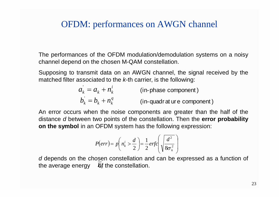
The performances of the OFDM modulation/demodulation systems on a noisychannel depend on the chosen M-QAM constellation.
Supposing to transmit data on an AWGN channel, the signal received by thematched filter associated to the k-th carrier, is the following:
An error occurs when the noise components are greater than the half of thedistance d between two points of the constellation. Then the error probabilityon the symbol in an OFDM system has the following expression:
d depends on the chosen constellation and can be expressed as a function ofthe average energy of the constellation.
OFDM: performances on AWGN channel
2
2
821
2 k
ik
derfcdnperrP
ikkk naa ' (in-phase component)qkkk nbb ' (in-quadrature component)
cE
24
OFDM: performances on AWGN channel
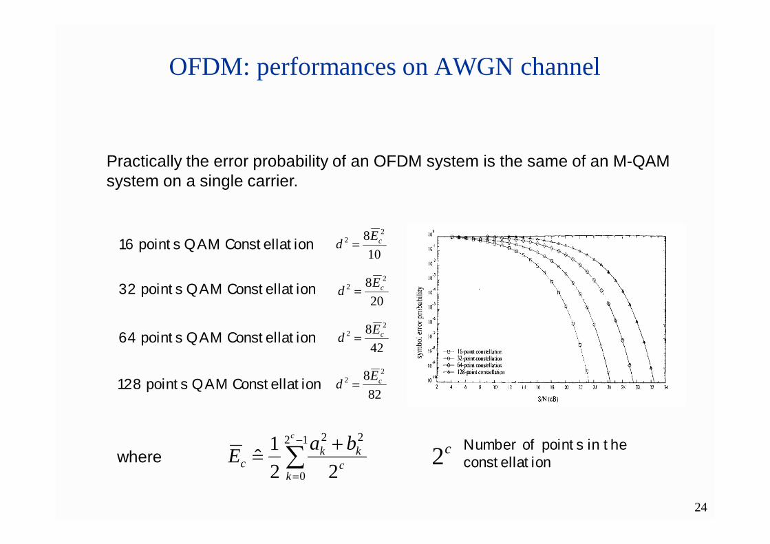
Practically the error probability of an OFDM system is the same of an M-QAM system on a single carrier.
16 points QAM Constellation10
8 22 cEd
208 2
2 cEd
428 2
2 cEd
828 2
2 cEd
12
0
22
221
ˆc
kc
kkc
baE Number of points in the constellation
32 points QAM Constellation
64 points QAM Constellation
128 points QAM Constellation
c2where

25
OFDM: performances with pulse noise
The OFDM modulation offers remarkable robustness properties againstimpulsive noises, where impulsive noise is defined as a rectangular pulsewith limited amplitude and duration (generally inferior than the symbol time).Hence it is a wide band disturb.
Since the information is coded in the frequency domain, the energy of the noisepulse is distributed on the entire bandwidth of the spectrum. This fact reduceits effect on the signal sub-carriers.
The following figure shows the errorprobability versus the impulsive signal-to-noise ratio.
26
OFDM: performances with jamming noise
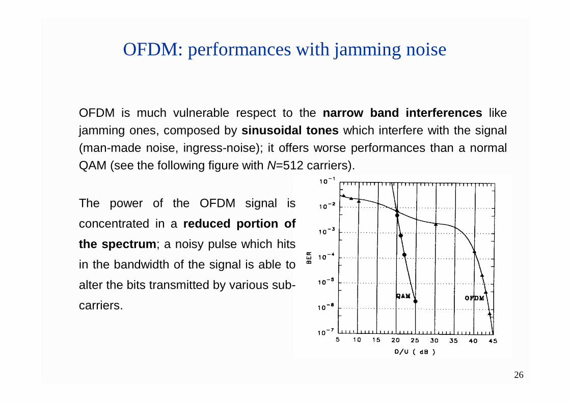
OFDM is much vulnerable respect to the narrow band interferences likejamming ones, composed by sinusoidal tones which interfere with the signal(man-made noise, ingress-noise); it offers worse performances than a normalQAM (see the following figure with N=512 carriers).
The power of the OFDM signal is
concentrated in a reduced portion ofthe spectrum; a noisy pulse which hits
in the bandwidth of the signal is able to
alter the bits transmitted by various sub-
carriers.

27
OFDM: performances with jamming noise
A possible solution consist in switching off the sub-carriers corrupted by the
jamming pulse. This solution succeed if the position of the interfering tone in
the frequency domain is fixed and known. It can be implemented without any
additional hardware, by using the IFFT properties.
If the position of the interfering tone is not fixed known, a FEC coding has to
be introduced before the modulator (called Coded-OFDM or COFDM)
28
OFDM: behave on multipath channel
After a multipath channel, a series of delayed and out of phase replica of thedesired signal are received.
Hence, sampling the signal on a certain instant, a linear combination of theprevious symbol of the current symbol, and of the following symbol isobtained (ISI); then the channel behaves like a linear filter.
Theoretically, it could be possible to use the inverse equalizers, which aredigital filters whose the coefficients are dynamically updated by properalgorithms.
The coefficients updating is a computationally heavy operation andsubstantially inefficient if the delay spread of the channel is greater than themodulation period (this condition is equivalent to the frequency selectivityfor the multipath fading)
The OFDM techniques allow to increase the modulation period and togenerate a modulated signal for which the channel is not frequency selective;but the bit-rate remain the same.

29
OFDM: behave on multipath channel
Supposing to introduce a multipath channel with discreet paths, it can berepresented by the following impulse response:
P
ppp tAth
0
)(
ttth )(
tststs )('
Without losing generality, an extremely simplified model of the multipathchannel can be assumed:
The signal received by every single carrier can be written as a summation of the LoS signal and its delayed echo.
It is impossible to insulate (seefigure) an interval of T secondswhich contains only one symbol:ISI appears.
30
OFDM: behave on multipath channel
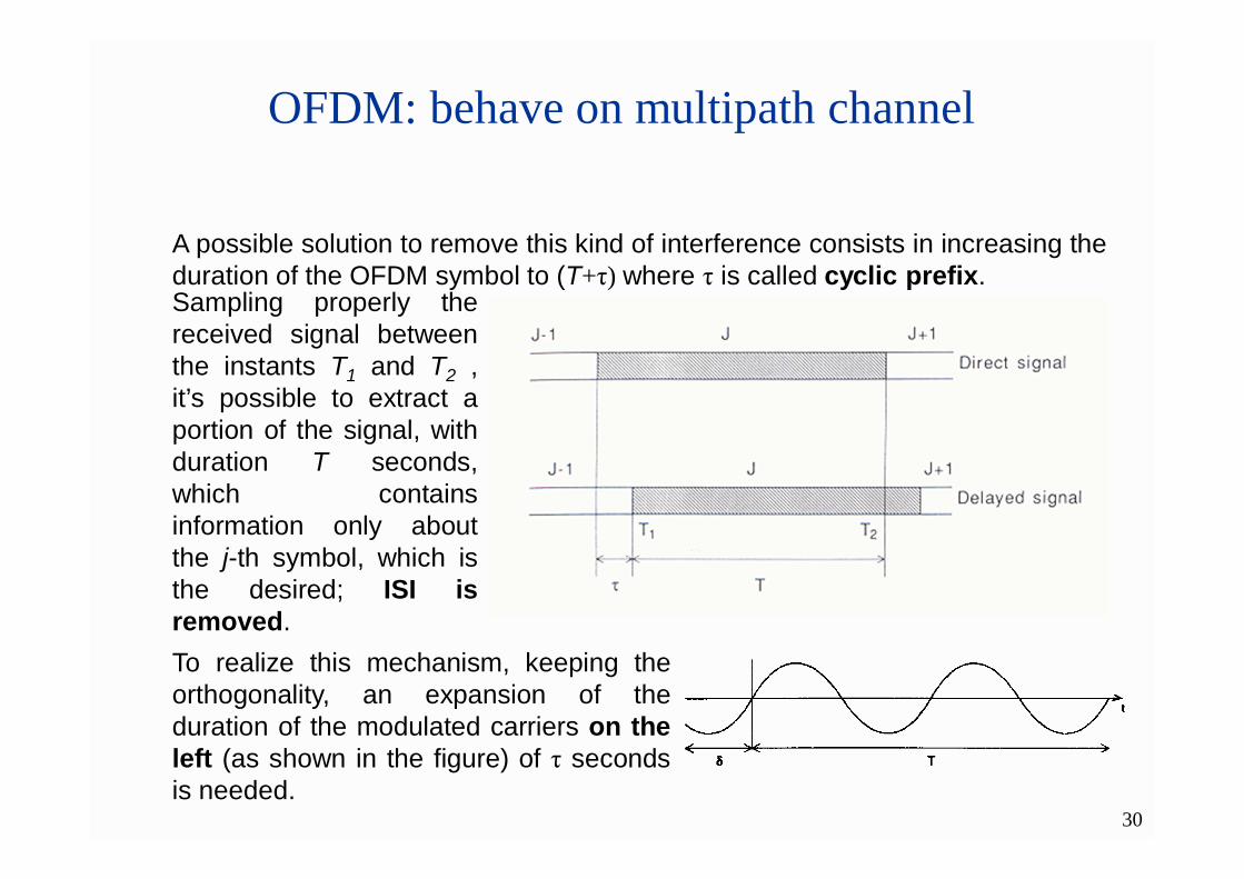
A possible solution to remove this kind of interference consists in increasing theduration of the OFDM symbol to (T+τ) where τ is called cyclic prefix.Sampling properly thereceived signal betweenthe instants T1 and T2 ,it’s possible to extract aportion of the signal, withduration T seconds,which containsinformation only aboutthe j-th symbol, which isthe desired; ISI isremoved.To realize this mechanism, keeping theorthogonality, an expansion of theduration of the modulated carriers on theleft (as shown in the figure) of τ secondsis needed.
31
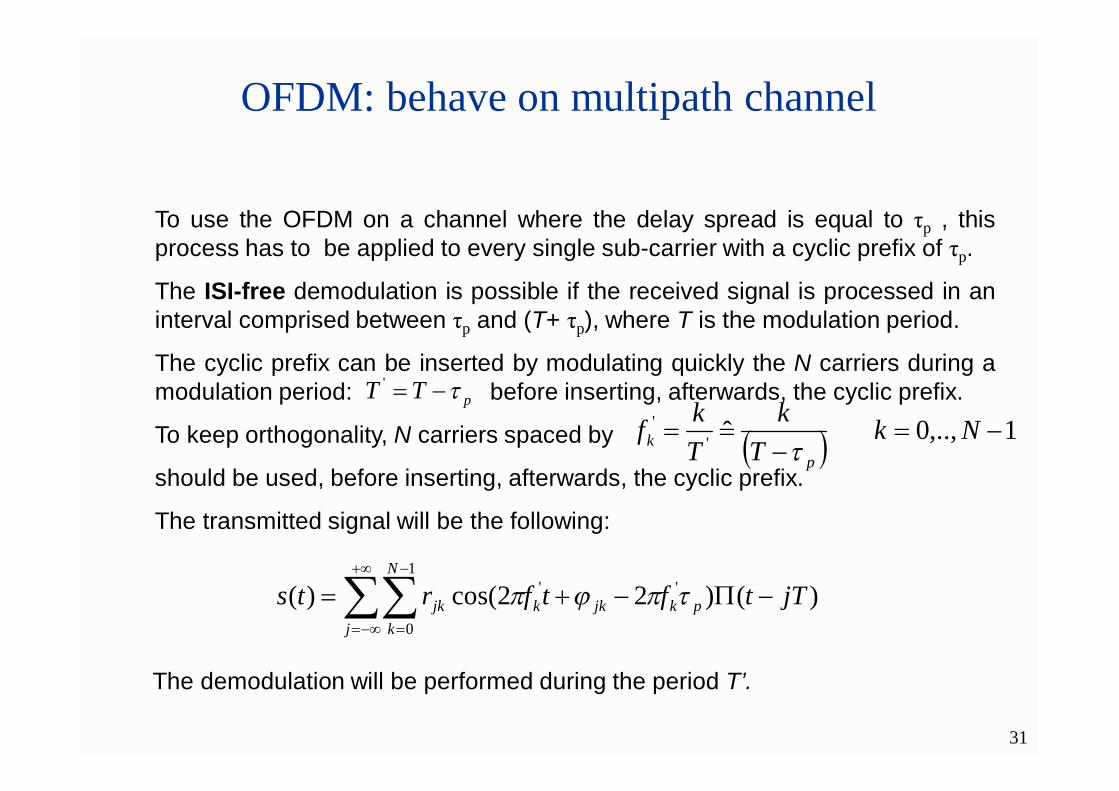
To use the OFDM on a channel where the delay spread is equal to τp , thisprocess has to be applied to every single sub-carrier with a cyclic prefix of τp.
The ISI-free demodulation is possible if the received signal is processed in aninterval comprised between τp and (T+ τp), where T is the modulation period.
The cyclic prefix can be inserted by modulating quickly the N carriers during amodulation period: before inserting, afterwards, the cyclic prefix.
To keep orthogonality, N carriers spaced by
should be used, before inserting, afterwards, the cyclic prefix.
The transmitted signal will be the following:
OFDM: behave on multipath channel
pTT '
1,..,0 ˆ''
Nk
Tk
Tkf
pk
j
N
kpkjkkjk jTtftfrts
1
0
'' )()22cos()(
The demodulation will be performed during the period T’.

32
OFDM: behave on multipath channel
a
TNTN
WD
p
p
65'
DNaT
The use of the cyclic prefix can limit the spectral efficiency of the modulation. It can be shown that the spectral efficiency of an OFDM system with cyclic prefix τp is equal to:
Where T is fixed and it’s equal to:
The following figure shows therequired bandwidth as a functionof the number of the orthogonalcarriers, with D=34Mb/s,a=3,4,5,6 e τp = 8msec.