radview -...
TRANSCRIPT
RADview Element Management System
Optimux-4E1, Optimux-4T1 Optimux-4E1L, Optimux-4T1L
© 1994–2005 RAD Data Communications Publication 07/05

RADview Optimux-4E1/Optimux-4T1 Network Management Software Guide i
Contents
Chapter 1. Introduction 1.1 Overview..................................................................................................................... 1-1
General ................................................................................................................................1-1 Features................................................................................................................................1-1 Application ...........................................................................................................................1-2
1.2 Functional Description................................................................................................. 1-2 Test and Diagnostic Capabilities ............................................................................................1-2 Fiber Optic Link....................................................................................................................1-2 Tributary Interface Characteristics .........................................................................................1-3 Alarms and Alarm Indications................................................................................................1-3
Chapter 2. Installation and Setup 2.1 Configuring for Management ....................................................................................... 2-1
Setting up the Manager List ...................................................................................................2-2 Setting the Management Access ............................................................................................2-2
2.2 Connecting Optimux-4E1/Optimux-4T1 for Management............................................ 2-3 2.3 Configuring Optimux-4E1L/Optimux-4T1L Control Port for Management .................... 2-4
Configuring the Control Port for PPP mode ...........................................................................2-4 Returning the Control Port to Terminal Mode........................................................................2-4
2.4 Using the Graphical User Interface .............................................................................. 2-5 Menu Bar .............................................................................................................................2-6 Status Bar .............................................................................................................................2-6 LEDs.....................................................................................................................................2-7
2.5 System Level Operations.............................................................................................. 2-7 2.6 Device Level Operations.............................................................................................. 2-8 2.7 Port Level Operations .................................................................................................. 2-9
Chapter 3. Configuration Management 3.1 System Level – Configuration Menu............................................................................. 3-1
Viewing and Setting System Information................................................................................3-1 Polling the Agents .................................................................................................................3-3
3.2 System Level – Options Menu ..................................................................................... 3-3 Configuring the Manager List.................................................................................................3-3 Configuring Access Restrictions .............................................................................................3-5 Configuring Automatic Polling...............................................................................................3-6
3.3 Device Level – Configuration Menu............................................................................. 3-6 Configuring Device Parameters .............................................................................................3-6 Viewing Interface Information ...............................................................................................3-8 Resetting the Hardware.........................................................................................................3-9 Resetting the Configuration ...................................................................................................3-9
3.4 Port Level – Configuration Menu ............................................................................... 3-10 Configuring Link Parameters ...............................................................................................3-10 Configuring Channel Parameters .........................................................................................3-12
Table of Contents
ii RADview Optimux-4E1/Optimux-4T1 Network Management Software Guide
Chapter 4. Fault Management 4.1 System Level Fault Management – Fault Menu............................................................. 4-1
Displaying the Alarm Buffer List.............................................................................................4-1 Clearing the Alarm Buffer......................................................................................................4-3
4.2 Device Level Fault Management – Fault Menu............................................................. 4-3 Displaying the Alarms ...........................................................................................................4-3 Configuring Channel Alarm Masks.........................................................................................4-5
4.3 Device Level Fault Management – Diagnostics Menu................................................... 4-6 Viewing the Lines Status........................................................................................................4-6 Running a Loopback Test on a Device...................................................................................4-7
4.4 Port Level Fault Management – Fault Menu ................................................................. 4-8 Displaying the Alarms for a Link ............................................................................................4-9 Displaying the Alarms for a Channel....................................................................................4-10
4.5 Port Level Fault Management – Diagnostics Menu ..................................................... 4-11 Running a Loopback Test on a Link.....................................................................................4-11 Running a Loopback Test on a Channel ..............................................................................4-13
List of Figures 1-1 Typical Application.................................................................................................................. 1-2 2-1. Host IP List Menu.................................................................................................................. 2-1 2-2. Manager List Screen .............................................................................................................. 2-2 2-3. Manager Access Menu........................................................................................................... 2-3 2-4. Telnet Menu.......................................................................................................................... 2-3 2-5. Management to Optimux-4E1 or Optimux-4T1 via Ethernet .................................................. 2-3 2-6. Management-to-MBE-to-Optimux-4E1L/4T1L Connection..................................................... 2-4 2-7. RADview Window................................................................................................................. 2-6 3-1. System Level Configuration Menu ......................................................................................... 3-1 3-2. System Information Dialog Box.............................................................................................. 3-2 3-3. System Level Options Menu .................................................................................................. 3-3 3-4. Manager List Dialog Box........................................................................................................ 3-4 3-5. Access Dialog Box ................................................................................................................. 3-5 3-6. Device Level Configuration Menu ......................................................................................... 3-6 3-7. Local Parameters Dialog Box ................................................................................................. 3-7 3-8. Remote Parameters Dialog Box ............................................................................................. 3-7 3-9. Local Interfaces Dialog Box ................................................................................................... 3-8 3-10. Remote Interfaces Dialog Box.............................................................................................. 3-8 3-11. Port Level Configuration Menu.......................................................................................... 3-10 3-12. Local Link Parameters Dialog Box...................................................................................... 3-10 3-13. Remote Link Parameters Dialog Box.................................................................................. 3-11 3-14. Local Channel Parameters Dialog Box ............................................................................... 3-12 3-15. Remote Channel Parameters Dialog Box ........................................................................... 3-12
Table of Contents
RADview Optimux-4E1/Optimux-4T1 Network Management Software Guide iii
4-1. System Level Fault Menu....................................................................................................... 4-1 4-2. Alarm Buffer List Dialog Box.................................................................................................. 4-2 4-3. Device Level Fault Menu....................................................................................................... 4-3 4-4. Device Alarms Dialog Box ..................................................................................................... 4-4 4-5. Mask Channel Alarm Dialog Box ........................................................................................... 4-5 4-6. Device Level Diagnostics Menu ............................................................................................. 4-6 4-7. Local Lines Status Dialog Box ................................................................................................ 4-6 4-8. Remote Lines Status Dialog Box............................................................................................. 4-7 4-9. Local Loopback Test Dialog Box............................................................................................ 4-8 4-10. Port Level Fault Menu ......................................................................................................... 4-8 4-11. Link Alarms Dialog Box ....................................................................................................... 4-9 4-12. Channel Alarms Dialog Box ............................................................................................... 4-10 4-13. Port Level Diagnostics Menu ............................................................................................. 4-11 4-14. Link Loopback Test Dialog Box.......................................................................................... 4-12 4-15. Local Channel Loopback Test Dialog Box .......................................................................... 4-13 4-16. Remote Channel Loopback Test Dialog Box ...................................................................... 4-14
Table of Contents
iv RADview Optimux-4E1/Optimux-4T1 Network Management Software Guide
List of Tables 2-1. Optimux-4E1/Optimux-4T1 LEDs.......................................................................................... 2-7 2-2. System Management Options ................................................................................................ 2-7 2-3. Device Management Options ................................................................................................ 2-8 2-4. Port Management Options .................................................................................................... 2-9 3-1. System Information Parameters ............................................................................................. 3-2 3-2. Manager List Parameters........................................................................................................ 3-4 3-3. Access Parameters ................................................................................................................. 3-5 3-4. Device Parameters ................................................................................................................ 3-7 3-5. Interface Parameters.............................................................................................................. 3-9 3-6. Link Parameters................................................................................................................... 3-11 3-7. Channel Parameters ............................................................................................................ 3-13 4-1. Alarm Buffer List Parameters.................................................................................................. 4-2 4-2. Device Alarms Parameters ..................................................................................................... 4-4 4-3. Mask Channel Alarm Parameters ........................................................................................... 4-5 4-4. Lines Status Parameters ......................................................................................................... 4-7 4-5. Local Loopback Test Parameters............................................................................................ 4-8 4-6. Link Alarms Parameters ......................................................................................................... 4-9 4-7. Channel Alarms Parameters................................................................................................. 4-10 4-8. Link Loopback Test Parameters ........................................................................................... 4-12 4-9. Channel Loopback Test Parameters ..................................................................................... 4-14
Overview 1-1
Chapter 1 Introduction
1.1 Overview
General Optimux-4E1 and Optimux-4T1 are second-order multiplexers that combine four E1/T1 tributary data streams into a single fiber optic link. Optimux-4E1L and Optimux-4T1L are low-cost versions of the standard standalone units.
The fiber optic interface provides a secure link in hazardous or hostile environments, increases the maximum connection range, and achieves immunity against electrical interference and protection against the harmful effects of ground loops.
Features The main features of the multiplexers are:
• Four E1/T1 multiplexed channels over a single fiber optic link
• A pair of Optimux-4E1/T1 units offers simple connectivity for four E1/T1 channels at distances of up to 120 km (74.5 miles)
• Operate with multimode or single mode fiber; and single mode over single fiber in the WDM module
• Transmit each of the E1/T1 channels independently, so that each E1/T1 channel can have its own clock source
• To facilitate system diagnostics, the units feature LED status indicators, AIS alarm generation, recognition, and dry contact closure upon link failure.
• Setup, control and diagnostics can be performed via a supervisory port using an ASCII terminal
• Conform to ITU G.703, G.823, G.824 and G.955
• Compact 1U high size.
Chapter 1 Introduction RADview Optimux-4E1/T1 User’s Manual
1-2 Functional Description
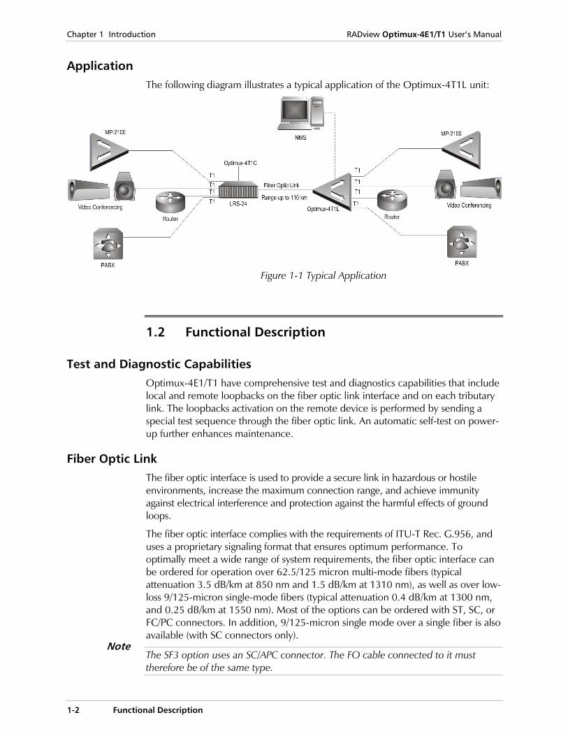
Application The following diagram illustrates a typical application of the Optimux-4T1L unit:
Figure 1-1 Typical Application
1.2 Functional Description
Test and Diagnostic Capabilities Optimux-4E1/T1 have comprehensive test and diagnostics capabilities that include local and remote loopbacks on the fiber optic link interface and on each tributary link. The loopbacks activation on the remote device is performed by sending a special test sequence through the fiber optic link. An automatic self-test on power-up further enhances maintenance.
Fiber Optic Link The fiber optic interface is used to provide a secure link in hazardous or hostile environments, increase the maximum connection range, and achieve immunity against electrical interference and protection against the harmful effects of ground loops.
The fiber optic interface complies with the requirements of ITU-T Rec. G.956, and uses a proprietary signaling format that ensures optimum performance. To optimally meet a wide range of system requirements, the fiber optic interface can be ordered for operation over 62.5/125 micron multi-mode fibers (typical attenuation 3.5 dB/km at 850 nm and 1.5 dB/km at 1310 nm), as well as over low-loss 9/125-micron single-mode fibers (typical attenuation 0.4 dB/km at 1300 nm, and 0.25 dB/km at 1550 nm). Most of the options can be ordered with ST, SC, or FC/PC connectors. In addition, 9/125-micron single mode over a single fiber is also available (with SC connectors only).
The SF3 option uses an SC/APC connector. The FO cable connected to it must therefore be of the same type.
Note
RADview Optimux-4E1/T1 User’s Manual Chapter 1 Introduction
Functional Description 1-3
Tributary Interface Characteristics The Optimux-4E1/T1 tributary interfaces meet the requirements of ITU-T Rec. G.703. Each tributary port has a 100Ω balanced line interface terminated in an RJ-45 eight-pin connector.
Line coding is B8ZS or AMI. The nominal balanced interface transmit level is ±3.0V. The line attenuation is up to 12 dB, and each E1/T1 signal is processed by an adaptive equalizer that compensates for various cable lengths to ensure optimal performance. Phase Locked Loops (PLL) are used to recover the clock signals, and the resulting jitter performance complies with the requirements of ITU-T Rec. G.824.
Each tributary interface has its own set of indicators that show the current state of the tributary link. The user can disable the alarm indications generated by unused interfaces (via internal switches, see section 2.5). AIS data streams are transmitted instead of failed or unconnected tributary data streams.
Alarms and Alarm Indications Optimux-4E1/T1 can detect the following alarm conditions on each E1/T1 and fiber optic interface:
• Loss of input signal
• Loss of frame synchronization
• Reception of alarm indication (AIS) signal, which consists of a continuous sequence of 1s.
When AIS is received, loss of frame synchronization occurs. However, in this case the alarm indicating loss of frame synchronization is suppressed.
When not all the tributaries are in use, the user can disable the alarm indications related to the unused tributaries.
The response to alarm conditions is as follows:
• AIS is transmitted on each tributary output in the following cases: Loss of fiber optic input signal is detected AIS is received on the fiber optic input Fiber optic frame synchronization is lost.
• An AIS signal is sent on a tributary instead of the tributary data stream through the fiber optic link in the following cases: Loss of tributary input signal is detected AIS is received on the tributary input Tributary frame synchronization is lost.
Front panel indicators display each alarm condition. In addition, a dedicated connector is used to provide major and minor alarm indications, by means of dry contacts.
Note
Chapter 1 Introduction RADview Optimux-4E1/T1 User’s Manual
1-4 Functional Description
The major alarm is activated in the following cases:
• Optimux-4E1/T1 is not powered, or power supply failure
• Loss of fiber optic input signal, or loss of fiber optic frame synchronization
• Loss of tributary input signals, or loss of frame synchronization.
The minor alarm is activated in the following cases:
• Reception of AIS signal on the fiber optic input
• Reception of AIS signal on tributary inputs.
An optional 5 VDC/100 mA pin is available for the user to be able to operate the external alarm system (small lamp, buzzer, etc.).
An additional (optional) input alarm signal (EXTERNAL ALARM) allows the user to inform Optimux-4E1/T1 that the user system is reporting alarm status. This input signal supports RS-232 levels.
Configuring for Management 2-1
Chapter 2 Installation and Setup This chapter provides instructions for configuring and connecting the Optimux-4E1/Optimux-4T1 or the Optimux-4E1L/Optimux-4T1L units for use with RADview.
2.1 Configuring for Management
All units Optimux-4E1/4T1 or Optimux-4E1L/4T1L must be configured via the terminal for management before connecting to the network.
To configure a unit for management:
1. Follow the path: Main Menu > Configuration > System Configuration > Management > Device Info.
2. Complete the details for the System Contact, System Name, and System Location. To define a system contact person, choose System Contact and then enter
the name, phone and/or other details you want to save in this field.
To specify a name to identify the device, choose System Name and then enter the name. It is easier to identify the device by a name than by its IP address.
To specify a system location, choose System Location and then enter the location of the unit.
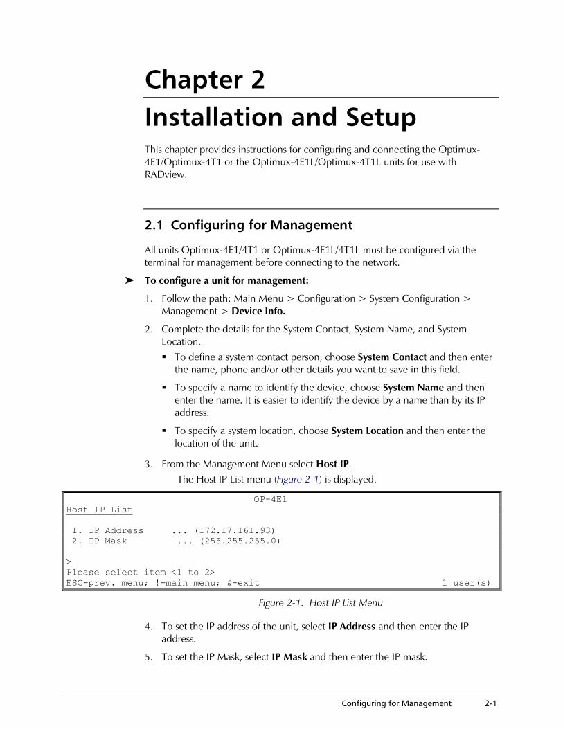
3. From the Management Menu select Host IP. The Host IP List menu (Figure 2-1) is displayed.
OP-4E1 Host IP List 1. IP Address ... (172.17.161.93) 2. IP Mask ... (255.255.255.0) > Please select item <1 to 2> ESC-prev. menu; !-main menu; &-exit 1 user(s)
Figure 2-1. Host IP List Menu
4. To set the IP address of the unit, select IP Address and then enter the IP address.
5. To set the IP Mask, select IP Mask and then enter the IP mask.
Chapter 2 Installation and Setup RADview Optimux-4E1/Optimux-4T1 User’s Manual
2-2 Configuring for Management
6. To set the default gateway, go back to the Host IP menu, select Default Gateway and then enter the IP address of the gateway.
7. From the Host IP menu, choose Read Community and then specify a string of eight characters. This field is used by SNMP.
8. From the Host IP menu, choose Write Community and then specify a string of eight characters. This field is used by SNMP.
9. From the Host IP menu, choose Trap Community and then specify a string of eight characters. This field is used by SNMP.
Setting up the Manager List By default, any remote management terminal is allowed to change the configuration of the Optimux device. You may enhance the security of the site by limiting remote management to specific management terminals or nodes. The Manager List lists the network nodes from which management may take place.
To define the manager list:
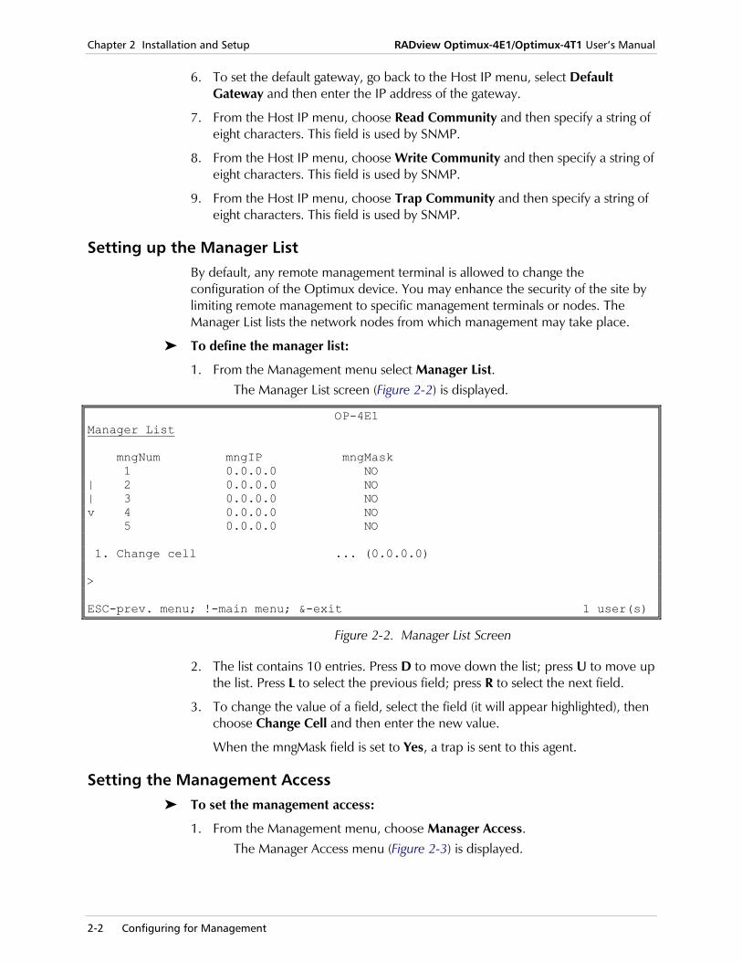
1. From the Management menu select Manager List. The Manager List screen (Figure 2-2) is displayed.
OP-4E1 Manager List mngNum mngIP mngMask 1 0.0.0.0 NO | 2 0.0.0.0 NO | 3 0.0.0.0 NO v 4 0.0.0.0 NO 5 0.0.0.0 NO 1. Change cell ... (0.0.0.0) > ESC-prev. menu; !-main menu; &-exit 1 user(s)
Figure 2-2. Manager List Screen
2. The list contains 10 entries. Press D to move down the list; press U to move up the list. Press L to select the previous field; press R to select the next field.
3. To change the value of a field, select the field (it will appear highlighted), then choose Change Cell and then enter the new value.
When the mngMask field is set to Yes, a trap is sent to this agent.
Setting the Management Access To set the management access:
1. From the Management menu, choose Manager Access. The Manager Access menu (Figure 2-3) is displayed.
RADview Optimux-4E1/Optimux-4T1 User’s Manual Chapter 2 Installation and Setup
Connecting Optimux-4E1/Optimux-4T1 for Management 2-3
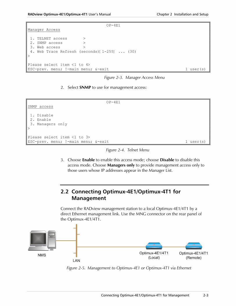
OP-4E1 Manager Access 1. TELNET access > 2. SNMP access > 3. Web access > 4. Web Trace Refresh (seconds)[1-255] ... (30) > Please select item <1 to 4> ESC-prev. menu; !-main menu; &-exit 1 user(s)
Figure 2-3. Manager Access Menu
2. Select SNMP to use for management access:
OP-4E1 SNMP access 1. Disable 2. Enable 3. Managers only > Please select item <1 to 3> ESC-prev. menu; !-main menu; &-exit 1 user(s)
Figure 2-4. Telnet Menu
3. Choose Enable to enable this access mode; choose Disable to disable this access mode. Choose Managers only to provide management access only to those users whose IP addresses appear in the Manager List.
2.2 Connecting Optimux-4E1/Optimux-4T1 for Management
Connect the RADview management station to a local Optimux-4E1/4T1 by a direct Ethernet management link. Use the MNG connector on the rear panel of the Optimux-4E1/4T1.
Figure 2-5. Management to Optimux-4E1 or Optimux-4T1 via Ethernet
Chapter 2 Installation and Setup RADview Optimux-4E1/Optimux-4T1 User’s Manual
2-4 Configuring Optimux-4E1L/Optimux-4T1L Control Port for Management
2.3 Configuring Optimux-4E1L/Optimux-4T1L Control Port for Management
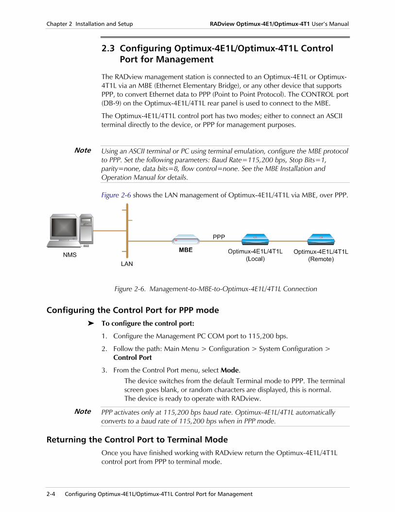
The RADview management station is connected to an Optimux-4E1L or Optimux-4T1L via an MBE (Ethernet Elementary Bridge), or any other device that supports PPP, to convert Ethernet data to PPP (Point to Point Protocol). The CONTROL port (DB-9) on the Optimux-4E1L/4T1L rear panel is used to connect to the MBE.
The Optimux-4E1L/4T1L control port has two modes; either to connect an ASCII terminal directly to the device, or PPP for management purposes.
Using an ASCII terminal or PC using terminal emulation, configure the MBE protocol to PPP. Set the following parameters: Baud Rate=115,200 bps, Stop Bits=1, parity=none, data bits=8, flow control=none. See the MBE Installation and Operation Manual for details.
Figure 2-6 shows the LAN management of Optimux-4E1L/4T1L via MBE, over PPP.
Figure 2-6. Management-to-MBE-to-Optimux-4E1L/4T1L Connection
Configuring the Control Port for PPP mode To configure the control port:
1. Configure the Management PC COM port to 115,200 bps.
2. Follow the path: Main Menu > Configuration > System Configuration > Control Port
3. From the Control Port menu, select Mode. The device switches from the default Terminal mode to PPP. The terminal screen goes blank, or random characters are displayed, this is normal. The device is ready to operate with RADview.
PPP activates only at 115,200 bps baud rate. Optimux-4E1L/4T1L automatically converts to a baud rate of 115,200 bps when in PPP mode. PPP
Returning the Control Port to Terminal Mode Once you have finished working with RADview return the Optimux-4E1L/4T1L control port from PPP to terminal mode.
Note
Note
RADview Optimux-4E1/Optimux-4T1 User’s Manual Chapter 2 Installation and Setup
Using the Graphical User Interface 2-5
When in PPP mode the control port is used as a management port. A terminal screen will be blank, or display random characters.
To return the control port to terminal mode:
1. Configure the PC COM port to 115,200 bps.
2. Press the <Enter> key on your keyboard.
3. Type monitor in the > prompt in the terminal.
4. Press the <Enter> key on your keyboard again. The device is now in terminal mode.
2.4 Using the Graphical User Interface
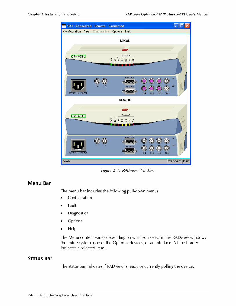
The RADview Optimux-4E1/Optimux-4T1 window provides a dynamically updated graphical representation of the Optimux-4E1/Optimux-4T1 devices at both ends of the link, allowing you to monitor and manage Optimux-4E1/Optimux-4T1 operations (see Figure 2-7).
The window includes:
• Link interfaces
• Channel interfaces
• LED operational and communication status indicators for each interface (LINK, CH1-CH4)
• LED status indicators for each device (PWR, TST)
When working with Optimux-4E1/4T1 new look vs. Optimux-4E1L/4T1L, the remote modem is displayed as old look. When the local modem is not new look, then the remote modem is displayed as the same as the local device.
Note
Note
Chapter 2 Installation and Setup RADview Optimux-4E1/Optimux-4T1 User’s Manual
2-6 Using the Graphical User Interface
Figure 2-7. RADview Window
Menu Bar The menu bar includes the following pull-down menus:
• Configuration
• Fault
• Diagnostics
• Options
• Help
The Menu content varies depending on what you select in the RADview window; the entire system, one of the Optimux devices, or an interface. A blue border indicates a selected item.
Status Bar The status bar indicates if RADview is ready or currently polling the device.
RADview Optimux-4E1/Optimux-4T1 User’s Manual Chapter 2 Installation and Setup
System Level Operations 2-7
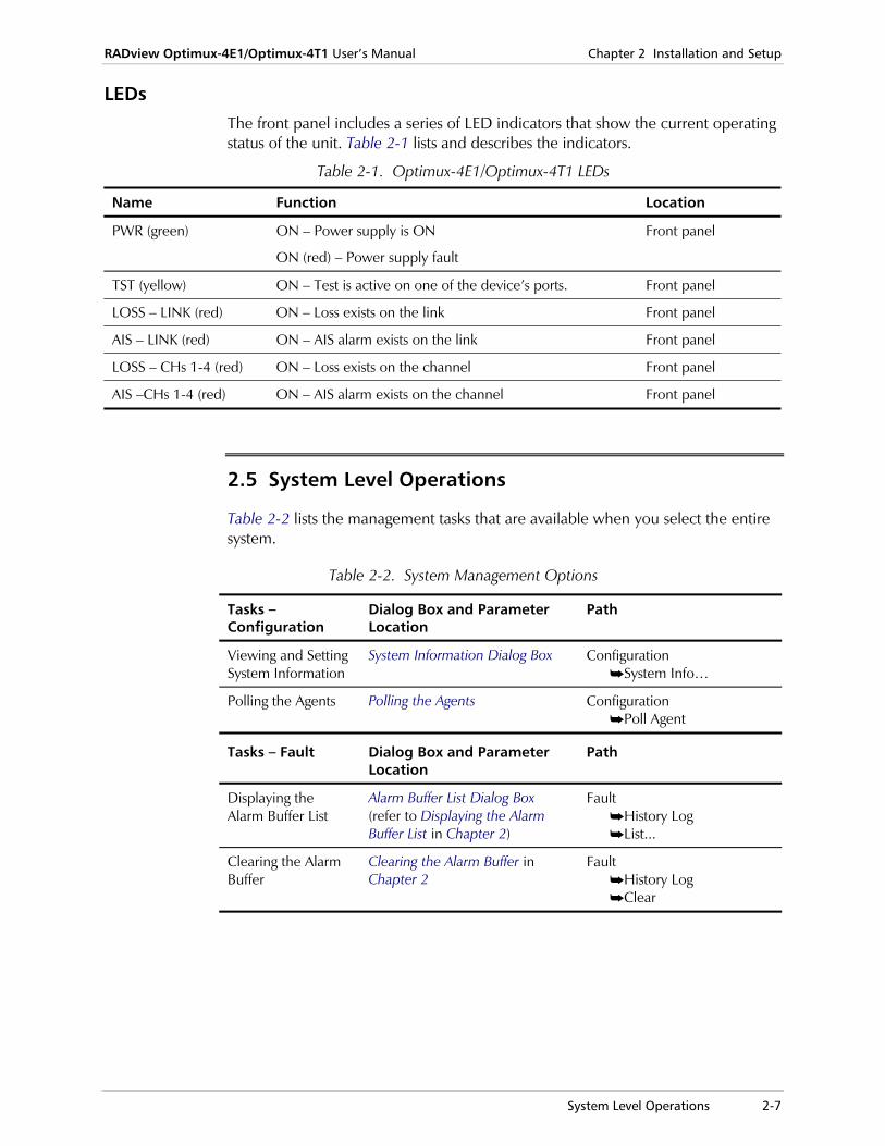
LEDs The front panel includes a series of LED indicators that show the current operating status of the unit. Table 2-1 lists and describes the indicators.
Table 2-1. Optimux-4E1/Optimux-4T1 LEDs
Name Function Location
PWR (green) ON – Power supply is ON
ON (red) – Power supply fault
Front panel
TST (yellow) ON – Test is active on one of the device’s ports. Front panel
LOSS – LINK (red) ON – Loss exists on the link Front panel
AIS – LINK (red) ON – AIS alarm exists on the link Front panel
LOSS – CHs 1-4 (red) ON – Loss exists on the channel Front panel
AIS –CHs 1-4 (red) ON – AIS alarm exists on the channel Front panel
2.5 System Level Operations
Table 2-2 lists the management tasks that are available when you select the entire system.
Table 2-2. System Management Options
Tasks – Configuration
Dialog Box and Parameter Location
Path
Viewing and Setting System Information
System Information Dialog Box Configuration System Info…
Polling the Agents Polling the Agents Configuration Poll Agent
Tasks – Fault Dialog Box and Parameter Location
Path
Displaying the Alarm Buffer List
Alarm Buffer List Dialog Box (refer to Displaying the Alarm Buffer List in Chapter 2)
Fault History Log List...
Clearing the Alarm Buffer
Clearing the Alarm Buffer in Chapter 2
Fault History Log Clear
Chapter 2 Installation and Setup RADview Optimux-4E1/Optimux-4T1 User’s Manual
2-8 Device Level Operations
Tasks – Options Dialog Box and Parameter Location
Path
Configuring the Manager List
Manager List Dialog Box (refer to Configuring the Manager List in Chapter 3)
Options Manager List...
Configuring Access Restrictions
Access Dialog Box (refer to Configuring Access Restrictions in Chapter 3)
Options Access...
Configuring Automatic Polling
Configuring Automatic Polling in Chapter 3)
Options Polling
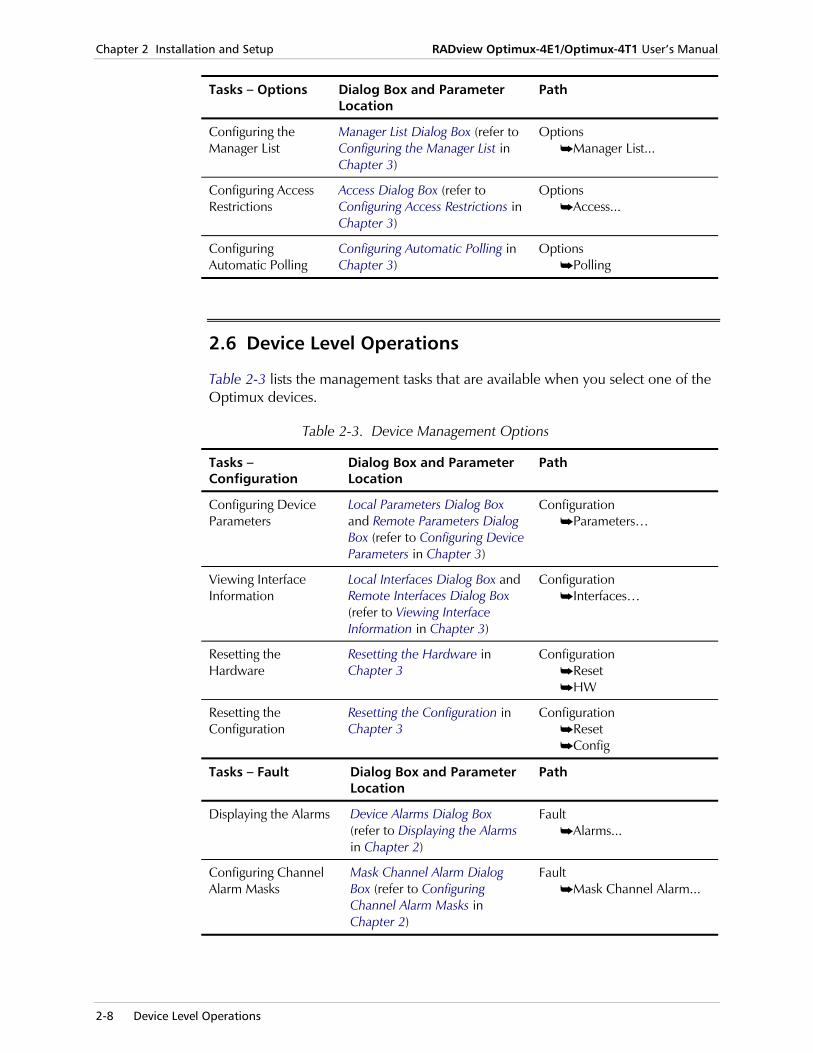
2.6 Device Level Operations
Table 2-3 lists the management tasks that are available when you select one of the Optimux devices.
Table 2-3. Device Management Options
Tasks – Configuration
Dialog Box and Parameter Location
Path
Configuring Device Parameters
Local Parameters Dialog Box and Remote Parameters Dialog Box (refer to Configuring Device Parameters in Chapter 3)
Configuration Parameters…
Viewing Interface Information
Local Interfaces Dialog Box and Remote Interfaces Dialog Box (refer to Viewing Interface Information in Chapter 3)
Configuration Interfaces…
Resetting the Hardware
Resetting the Hardware in Chapter 3
Configuration Reset HW
Resetting the Configuration
Resetting the Configuration in Chapter 3
Configuration Reset Config
Tasks – Fault Dialog Box and Parameter Location
Path
Displaying the Alarms Device Alarms Dialog Box (refer to Displaying the Alarms in Chapter 2)
Fault Alarms...
Configuring Channel Alarm Masks
Mask Channel Alarm Dialog Box (refer to Configuring Channel Alarm Masks in Chapter 2)
Fault Mask Channel Alarm...
RADview Optimux-4E1/Optimux-4T1 User’s Manual Chapter 2 Installation and Setup
Port Level Operations 2-9
Tasks – Diagnostics Dialog Box and Parameter Location
Path
Viewing the Lines Status
Local Lines Status Dialog Box and Remote Lines Status Dialog Box (refer to Viewing the Lines Status in Chapter 2)
Diagnostics Lines Status...
Running a Loopback Test
Local Loopback Test Dialog Box (refer to Running a Loopback Test on a Device in Chapter 2)
Diagnostics Loopback Test...
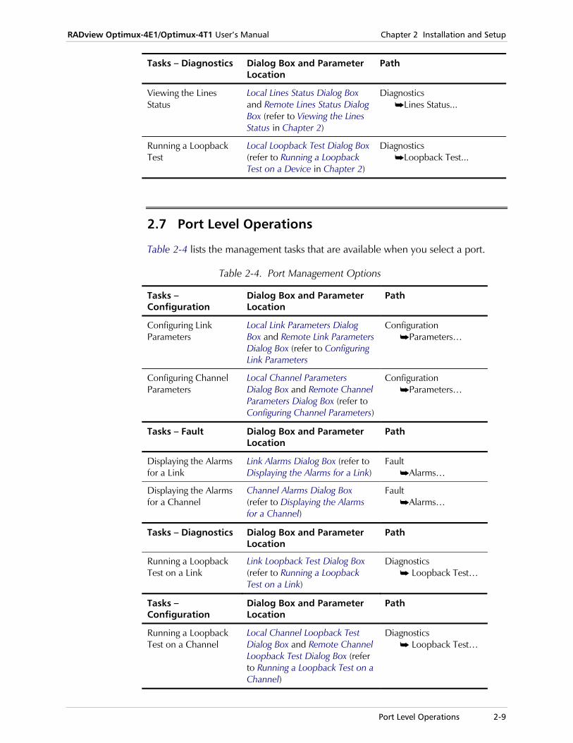
2.7 Port Level Operations
Table 2-4 lists the management tasks that are available when you select a port.
Table 2-4. Port Management Options
Tasks – Configuration
Dialog Box and Parameter Location
Path
Configuring Link Parameters
Local Link Parameters Dialog Box and Remote Link Parameters Dialog Box (refer to Configuring Link Parameters
Configuration Parameters…
Configuring Channel Parameters
Local Channel Parameters Dialog Box and Remote Channel Parameters Dialog Box (refer to Configuring Channel Parameters)
Configuration Parameters…
Tasks – Fault Dialog Box and Parameter Location
Path
Displaying the Alarms for a Link
Link Alarms Dialog Box (refer to Displaying the Alarms for a Link)
Fault Alarms…
Displaying the Alarms for a Channel
Channel Alarms Dialog Box (refer to Displaying the Alarms for a Channel)
Fault Alarms…
Tasks – Diagnostics Dialog Box and Parameter Location
Path
Running a Loopback Test on a Link
Link Loopback Test Dialog Box (refer to Running a Loopback Test on a Link)
Diagnostics Loopback Test…
Tasks – Configuration
Dialog Box and Parameter Location
Path
Running a Loopback Test on a Channel
Local Channel Loopback Test Dialog Box and Remote Channel Loopback Test Dialog Box (refer to Running a Loopback Test on a Channel)
Diagnostics Loopback Test…

Chapter 2 Installation and Setup RADview Optimux-4E1/Optimux-4T1 User’s Manual
2-10 Port Level Operations
System Level – Configuration Menu 3-1
Chapter 3 Configuration Management The chapter describes the Optimux-4E1/Optimux-4T1 configuration management at the system, device, and port levels.
3.1 System Level – Configuration Menu
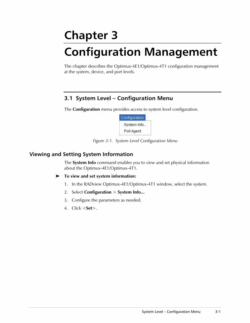
The Configuration menu provides access to system level configuration.
Figure 3-1. System Level Configuration Menu
Viewing and Setting System Information The System Info command enables you to view and set physical information about the Optimux-4E1/Optimux-4T1.
To view and set system information:
1. In the RADview Optimux-4E1/Optimux-4T1 window, select the system.
2. Select Configuration > System Info...
3. Configure the parameters as needed.
4. Click <Set>.
Chapter 3 Configuration Management RADview Optimux-4E1/Optimux-4T1 User’s Manual
3-2 System Level – Configuration Menu
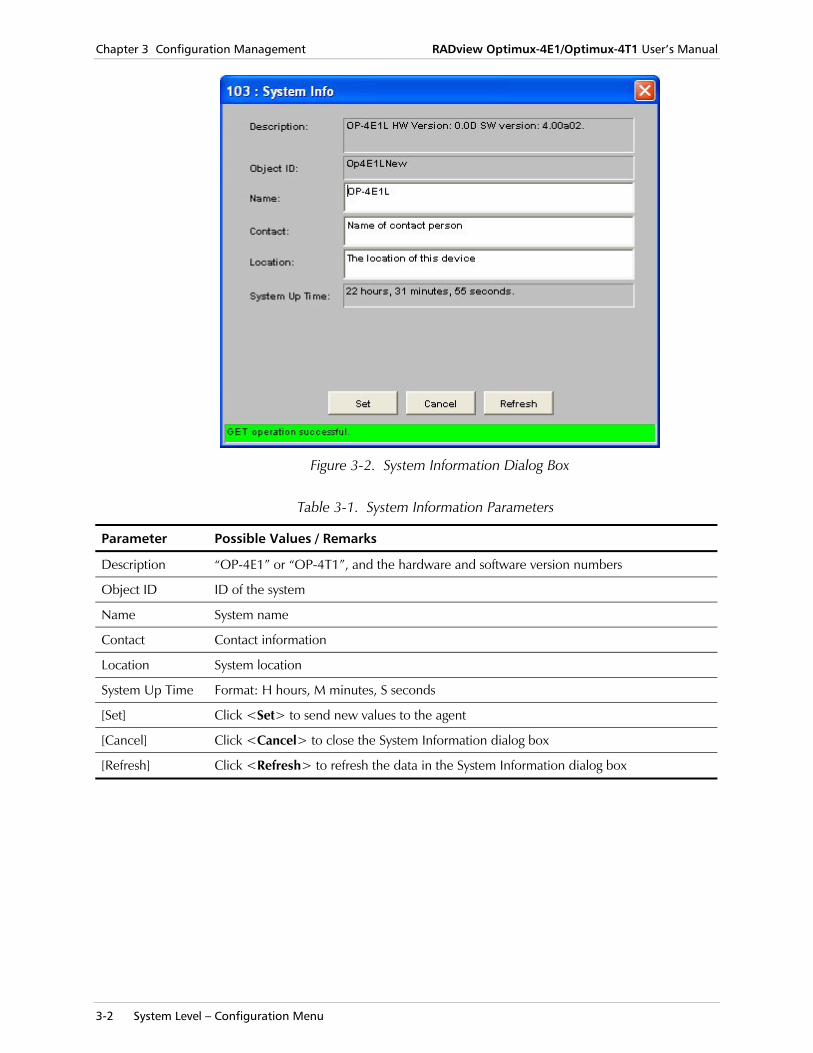
Figure 3-2. System Information Dialog Box
Table 3-1. System Information Parameters
Parameter Possible Values / Remarks
Description “OP-4E1” or “OP-4T1”, and the hardware and software version numbers
Object ID ID of the system
Name System name
Contact Contact information
Location System location
System Up Time Format: H hours, M minutes, S seconds
[Set] Click <Set> to send new values to the agent
[Cancel] Click <Cancel> to close the System Information dialog box
[Refresh] Click <Refresh> to refresh the data in the System Information dialog box
RADview Optimux-4E1/Optimux-4T1 User’s Manual Chapter 3 Configuration Management
System Level – Options Menu 3-3
Polling the Agents The Poll Agent command causes RADview-TDM to poll the agents on the local and remote devices. RADview-TDM polls the agents to get the current status of the Optimux devices.
If you enable automatic polling, RADview-TDM automatically polls the agents every sixty minutes. You can also poll the agents manually with the Poll Agent command. If you disable automatic polling, you must use the Poll Agent command to poll the agents. For more information about configuring automatic polling, see Configuring Automatic Polling on page 3-6.
To poll the agents:
1. In the RADview Optimux-4E1/Optimux-4T1 window, select the system.
2. Select Configuration > Poll Agent. The device immediately polls the agents.
3.2 System Level – Options Menu
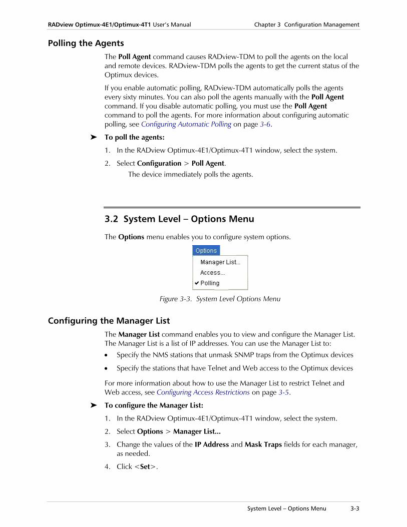
The Options menu enables you to configure system options.
Figure 3-3. System Level Options Menu
Configuring the Manager List The Manager List command enables you to view and configure the Manager List. The Manager List is a list of IP addresses. You can use the Manager List to:
• Specify the NMS stations that unmask SNMP traps from the Optimux devices
• Specify the stations that have Telnet and Web access to the Optimux devices
For more information about how to use the Manager List to restrict Telnet and Web access, see Configuring Access Restrictions on page 3-5.
To configure the Manager List:
1. In the RADview Optimux-4E1/Optimux-4T1 window, select the system.
2. Select Options > Manager List...
3. Change the values of the IP Address and Mask Traps fields for each manager, as needed.
4. Click <Set>.
Chapter 3 Configuration Management RADview Optimux-4E1/Optimux-4T1 User’s Manual
3-4 System Level – Options Menu
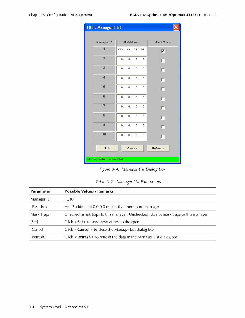
Figure 3-4. Manager List Dialog Box
Table 3-2. Manager List Parameters
Parameter Possible Values / Remarks
Manager ID 1..10
IP Address An IP address of 0.0.0.0 means that there is no manager
Mask Traps Checked: mask traps to this manager. Unchecked: do not mask traps to this manager
[Set] Click <Set> to send new values to the agent
[Cancel] Click <Cancel> to close the Manager List dialog box
[Refresh] Click <Refresh> to refresh the data in the Manager List dialog box
RADview Optimux-4E1/Optimux-4T1 User’s Manual Chapter 3 Configuration Management
System Level – Options Menu 3-5
Configuring Access Restrictions The Access command enables you to configure access restrictions for the local and remote devices. Access restrictions control whether a remote station can access the devices with Telnet and through the Web. You can configure the following access levels:
• Enable access to the device from all stations
• Disable access to the device from all stations
• Enable access to the device only from stations that are on the Manager List. For more information about the Manager List, see Configuring the Manager List on page 3-3.
To configure access restrictions:
1. In the RADview Optimux-4E1/Optimux-4T1 window, select the system.
2. Select Options > Access...
3. Change the values of the Telnet Access and Web Access fields, as needed.
4. Click <Set>.
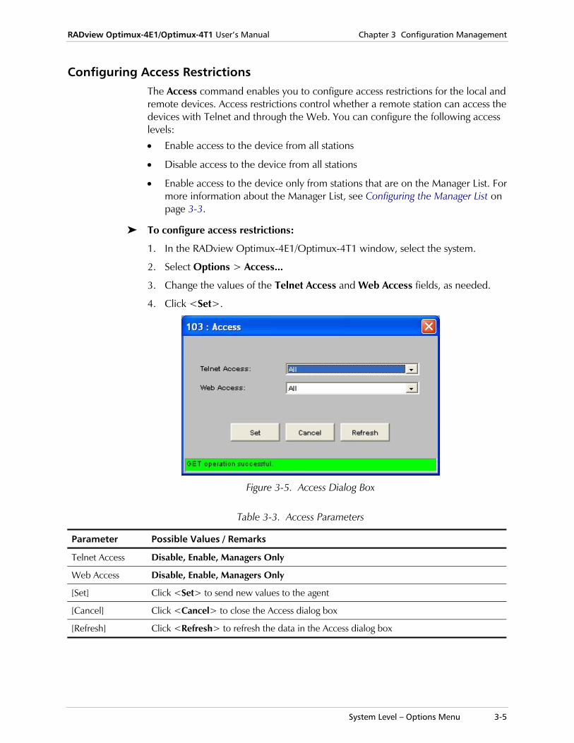
Figure 3-5. Access Dialog Box
Table 3-3. Access Parameters
Parameter Possible Values / Remarks
Telnet Access Disable, Enable, Managers Only
Web Access Disable, Enable, Managers Only
[Set] Click <Set> to send new values to the agent
[Cancel] Click <Cancel> to close the Access dialog box
[Refresh] Click <Refresh> to refresh the data in the Access dialog box
Chapter 3 Configuration Management RADview Optimux-4E1/Optimux-4T1 User’s Manual
3-6 Device Level – Configuration Menu
Configuring Automatic Polling The Polling command allows you to enable or disable automatic polling. RADview-TDM polls the agents on the local and remote devices to get the current status of the devices. If you enable automatic polling, RADview-TDM polls the agents every sixty minutes. If you disable automatic polling, you must use the Poll Agent command to poll the agents manually. For more information about the Poll Agent command, see Polling the Agents on page 3-3.
To configure automatic polling:
1. In the RADview Optimux-4E1/Optimux-4T1 window, select the system.
2. Open the Options menu.
3. Check or uncheck Polling, as needed.
3.3 Device Level – Configuration Menu
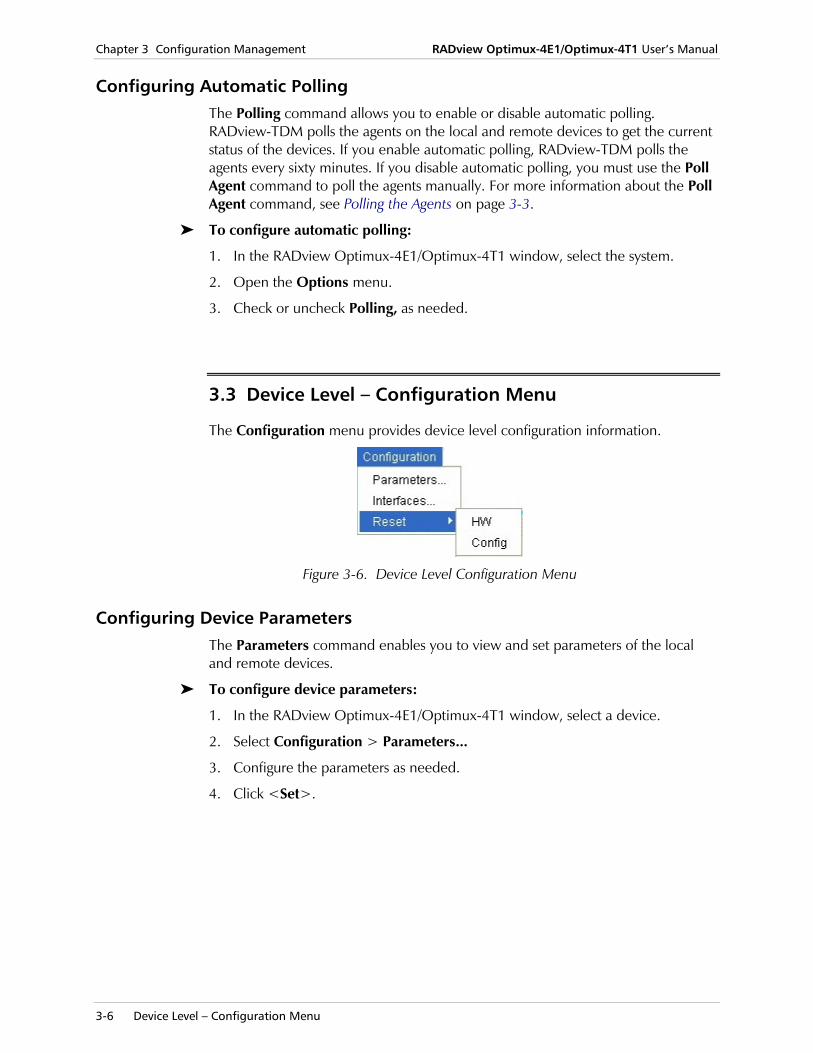
The Configuration menu provides device level configuration information.
Figure 3-6. Device Level Configuration Menu
Configuring Device Parameters The Parameters command enables you to view and set parameters of the local and remote devices.
To configure device parameters:
1. In the RADview Optimux-4E1/Optimux-4T1 window, select a device.
2. Select Configuration > Parameters...
3. Configure the parameters as needed.
4. Click <Set>.
RADview Optimux-4E1/Optimux-4T1 User’s Manual Chapter 3 Configuration Management
Device Level – Configuration Menu 3-7
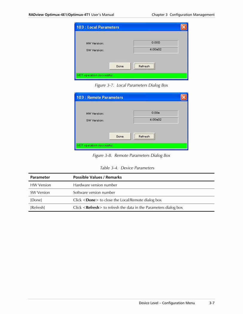
Figure 3-7. Local Parameters Dialog Box
Figure 3-8. Remote Parameters Dialog Box
Table 3-4. Device Parameters
Parameter Possible Values / Remarks
HW Version Hardware version number
SW Version Software version number
[Done] Click <Done> to close the Local/Remote dialog box
[Refresh] Click <Refresh> to refresh the data in the Parameters dialog box
Chapter 3 Configuration Management RADview Optimux-4E1/Optimux-4T1 User’s Manual
3-8 Device Level – Configuration Menu
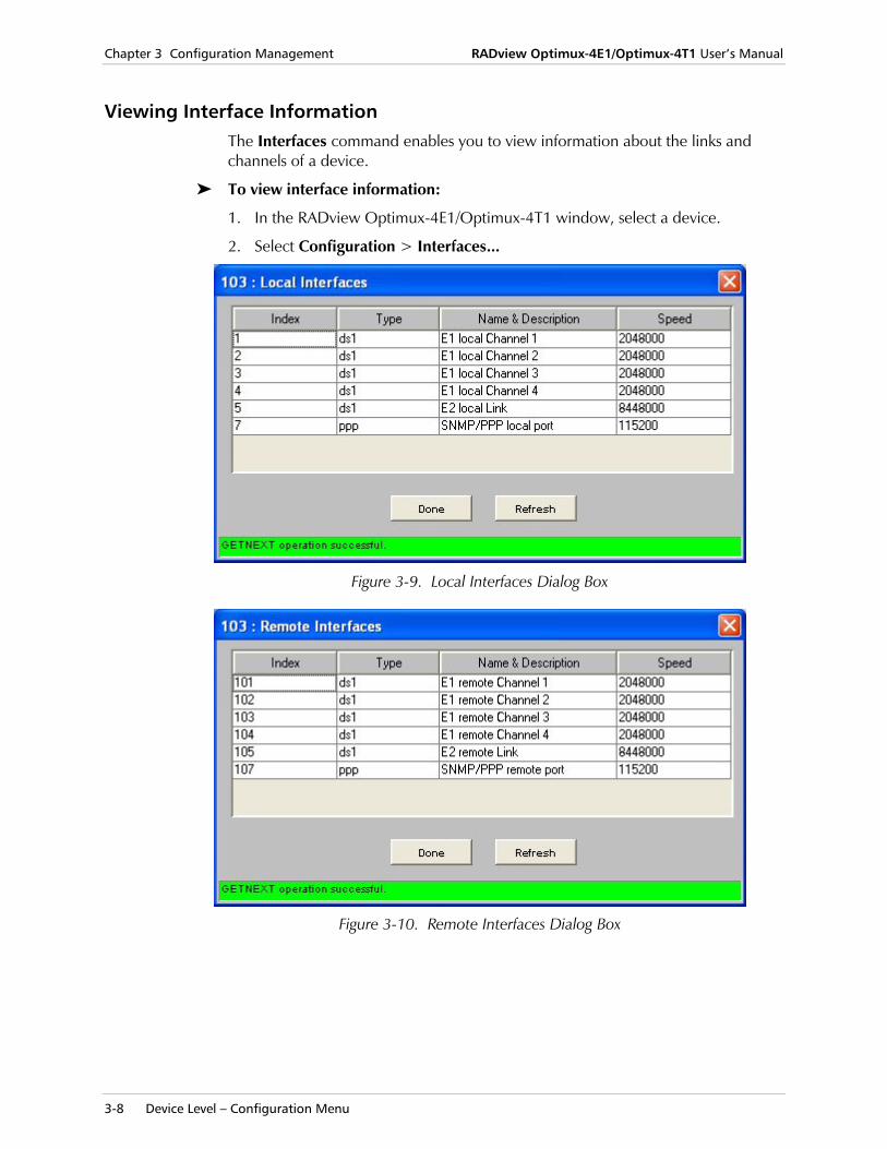
Viewing Interface Information The Interfaces command enables you to view information about the links and channels of a device.
To view interface information:
1. In the RADview Optimux-4E1/Optimux-4T1 window, select a device.
2. Select Configuration > Interfaces...
Figure 3-9. Local Interfaces Dialog Box
Figure 3-10. Remote Interfaces Dialog Box
RADview Optimux-4E1/Optimux-4T1 User’s Manual Chapter 3 Configuration Management
Device Level – Configuration Menu 3-9
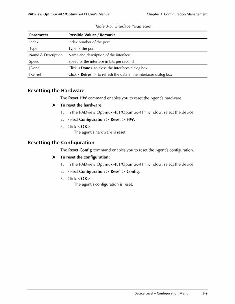
Table 3-5. Interface Parameters
Parameter Possible Values / Remarks
Index Index number of the port
Type Type of the port
Name & Description Name and description of the interface
Speed Speed of the interface in bits per second
[Done] Click <Done> to close the Interfaces dialog box
[Refresh] Click <Refresh> to refresh the data in the Interfaces dialog box
Resetting the Hardware The Reset HW command enables you to reset the Agent’s hardware.
To reset the hardware:
1. In the RADview Optimux-4E1/Optimux-4T1 window, select the device.
2. Select Configuration > Reset > HW.
3. Click <OK>. The agent’s hardware is reset.
Resetting the Configuration The Reset Config command enables you to reset the Agent’s configuration.
To reset the configuration:
1. In the RADview Optimux-4E1/Optimux-4T1 window, select the device.
2. Select Configuration > Reset > Config.
3. Click <OK>. The agent’s configuration is reset.
Chapter 3 Configuration Management RADview Optimux-4E1/Optimux-4T1 User’s Manual
3-10 Port Level – Configuration Menu
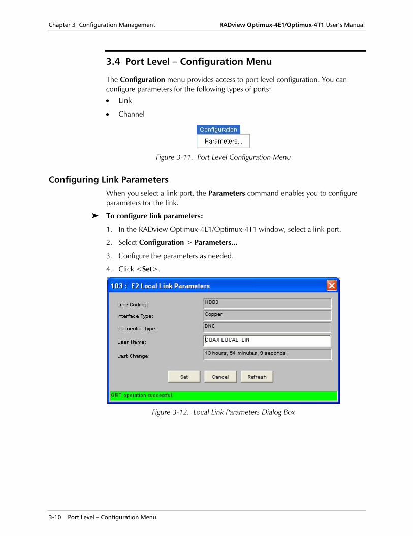
3.4 Port Level – Configuration Menu
The Configuration menu provides access to port level configuration. You can configure parameters for the following types of ports:
• Link
• Channel
Figure 3-11. Port Level Configuration Menu
Configuring Link Parameters When you select a link port, the Parameters command enables you to configure parameters for the link.
To configure link parameters:
1. In the RADview Optimux-4E1/Optimux-4T1 window, select a link port.
2. Select Configuration > Parameters...
3. Configure the parameters as needed.
4. Click <Set>.
Figure 3-12. Local Link Parameters Dialog Box
RADview Optimux-4E1/Optimux-4T1 User’s Manual Chapter 3 Configuration Management
Port Level – Configuration Menu 3-11
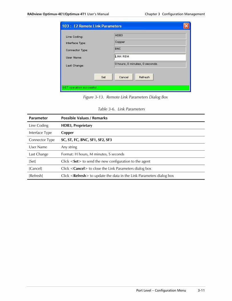
Figure 3-13. Remote Link Parameters Dialog Box
Table 3-6. Link Parameters
Parameter Possible Values / Remarks
Line Coding HDB3, Proprietary
Interface Type Copper
Connector Type SC, ST, FC, BNC, SF1, SF2, SF3
User Name Any string
Last Change Format: H hours, M minutes, S seconds
[Set] Click <Set> to send the new configuration to the agent
[Cancel] Click <Cancel> to close the Link Parameters dialog box
[Refresh] Click <Refresh> to update the data in the Link Parameters dialog box
Chapter 3 Configuration Management RADview Optimux-4E1/Optimux-4T1 User’s Manual
3-12 Port Level – Configuration Menu
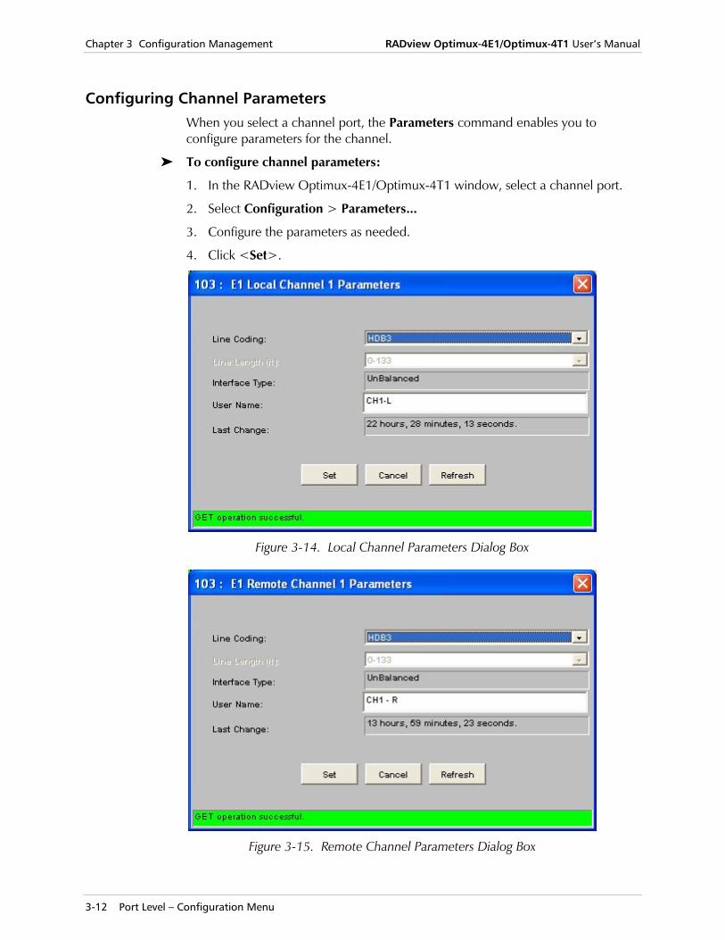
Configuring Channel Parameters When you select a channel port, the Parameters command enables you to configure parameters for the channel.
To configure channel parameters:
1. In the RADview Optimux-4E1/Optimux-4T1 window, select a channel port.
2. Select Configuration > Parameters...
3. Configure the parameters as needed.
4. Click <Set>.
Figure 3-14. Local Channel Parameters Dialog Box
Figure 3-15. Remote Channel Parameters Dialog Box
RADview Optimux-4E1/Optimux-4T1 User’s Manual Chapter 3 Configuration Management
Port Level – Configuration Menu 3-13
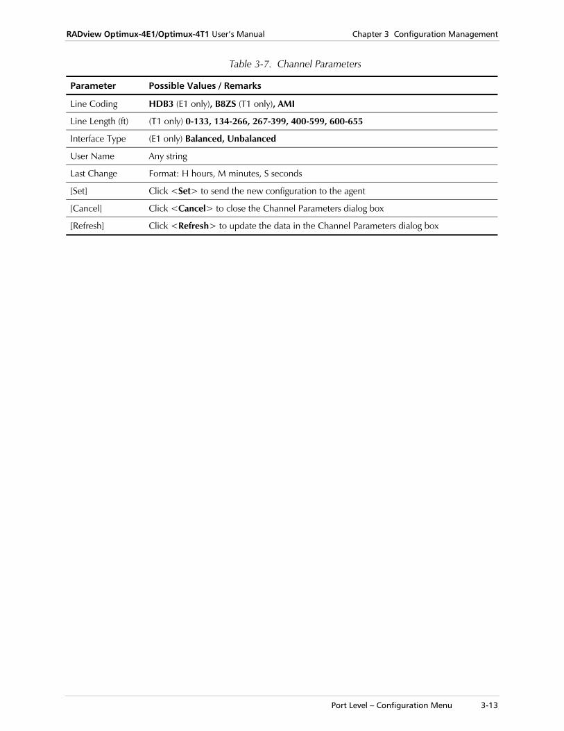
Table 3-7. Channel Parameters
Parameter Possible Values / Remarks
Line Coding HDB3 (E1 only), B8ZS (T1 only), AMI
Line Length (ft) (T1 only) 0-133, 134-266, 267-399, 400-599, 600-655
Interface Type (E1 only) Balanced, Unbalanced
User Name Any string
Last Change Format: H hours, M minutes, S seconds
[Set] Click <Set> to send the new configuration to the agent
[Cancel] Click <Cancel> to close the Channel Parameters dialog box
[Refresh] Click <Refresh> to update the data in the Channel Parameters dialog box

Chapter 3 Configuration Management RADview Optimux-4E1/Optimux-4T1 User’s Manual
3-14 Port Level – Configuration Menu
System Level Fault Management – Fault Menu 4-1
Chapter 4 Fault Management This chapter describes Optimux-4E1/Optimux-4T1 fault management at the system, device, and port levels.
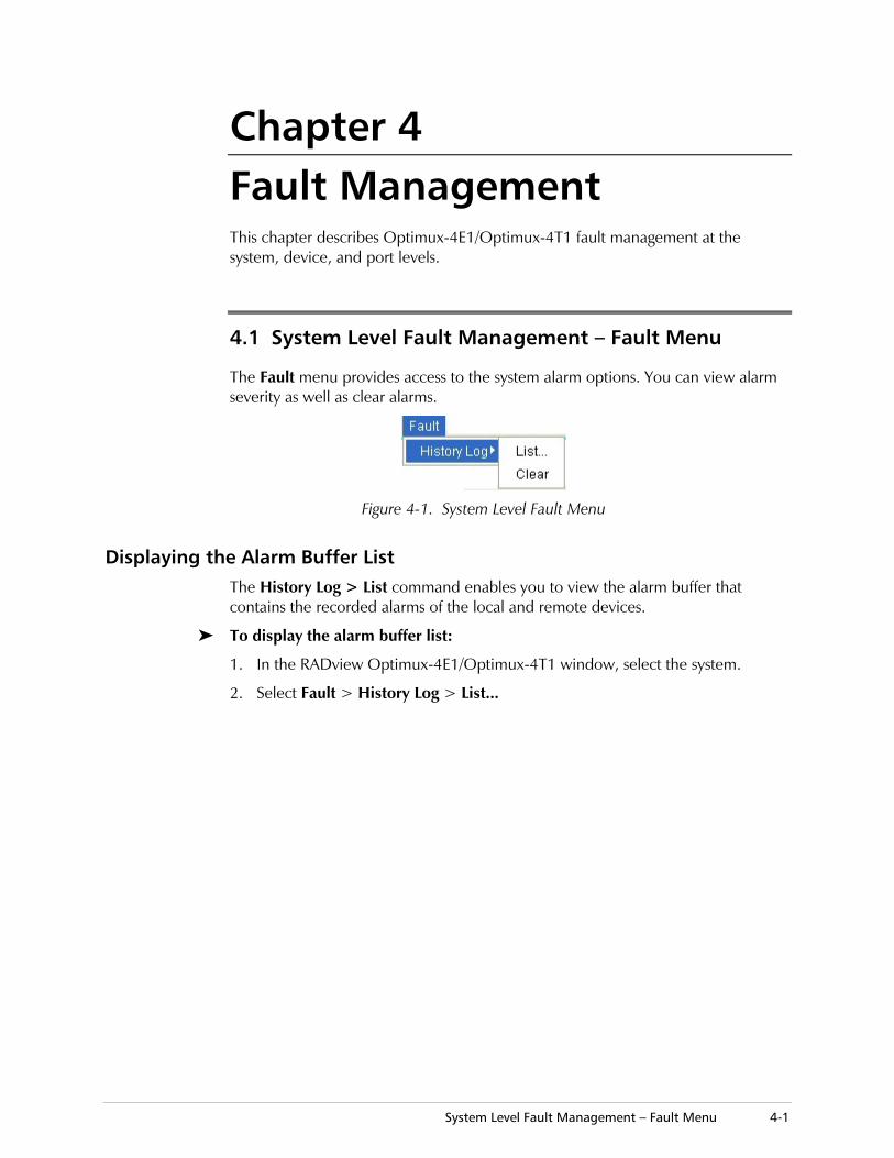
4.1 System Level Fault Management – Fault Menu
The Fault menu provides access to the system alarm options. You can view alarm severity as well as clear alarms.
Figure 4-1. System Level Fault Menu
Displaying the Alarm Buffer List The History Log > List command enables you to view the alarm buffer that contains the recorded alarms of the local and remote devices.
To display the alarm buffer list:
1. In the RADview Optimux-4E1/Optimux-4T1 window, select the system.
2. Select Fault > History Log > List...
Chapter 4 Fault Management RADview Optimux-4E1/Optimux-4T1 User’s Manual
4-2 System Level Fault Management – Fault Menu
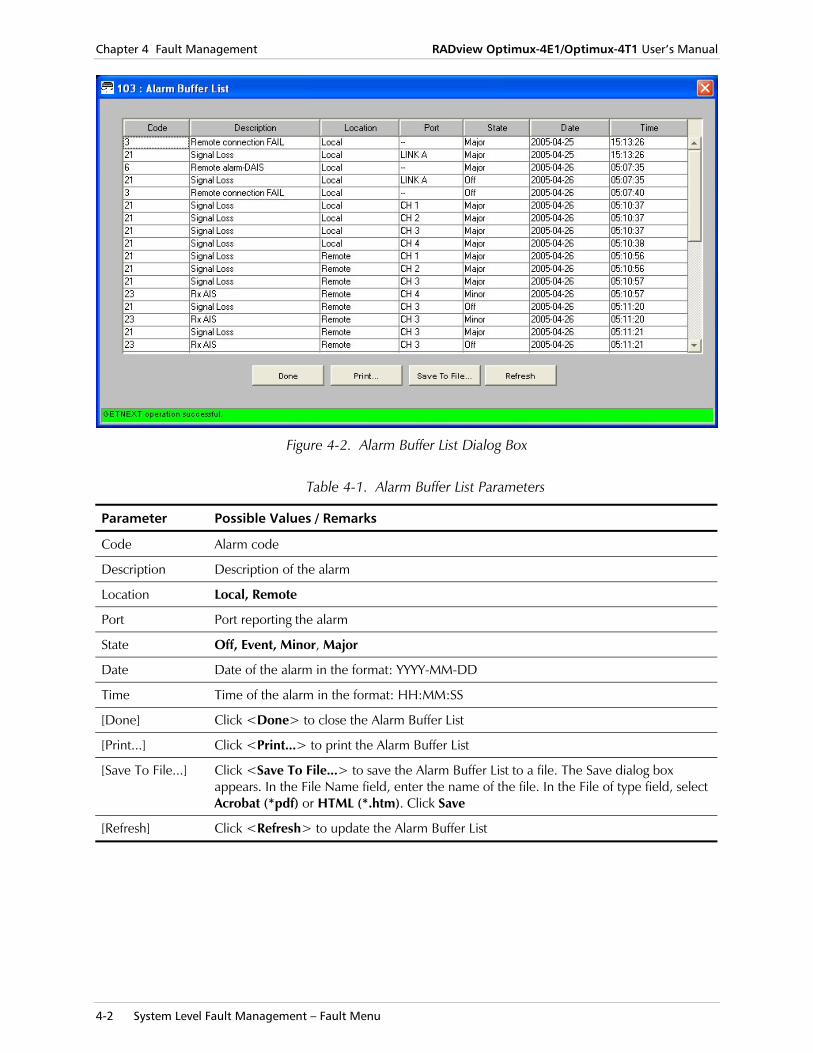
Figure 4-2. Alarm Buffer List Dialog Box
Table 4-1. Alarm Buffer List Parameters
Parameter Possible Values / Remarks
Code Alarm code
Description Description of the alarm
Location Local, Remote
Port Port reporting the alarm
State Off, Event, Minor, Major
Date Date of the alarm in the format: YYYY-MM-DD
Time Time of the alarm in the format: HH:MM:SS
[Done] Click <Done> to close the Alarm Buffer List
[Print...] Click <Print...> to print the Alarm Buffer List
[Save To File...] Click <Save To File...> to save the Alarm Buffer List to a file. The Save dialog box appears. In the File Name field, enter the name of the file. In the File of type field, select Acrobat (*pdf) or HTML (*.htm). Click Save
[Refresh] Click <Refresh> to update the Alarm Buffer List
RADview Optimux-4E1/Optimux-4T1 User’s Manual Chapter 4 Fault Management
Device Level Fault Management – Fault Menu 4-3
Clearing the Alarm Buffer The History Log > Clear command enables you to clear all entries in the alarm buffer.
To clear the alarm buffer:
1. In the RADview Optimux-4E1/Optimux-4T1 window, select the system.
2. Select Fault > History Log > Clear. The next time you view the Alarm Buffer List, only alarms that occur after the Clear operation appear in the list.
4.2 Device Level Fault Management – Fault Menu
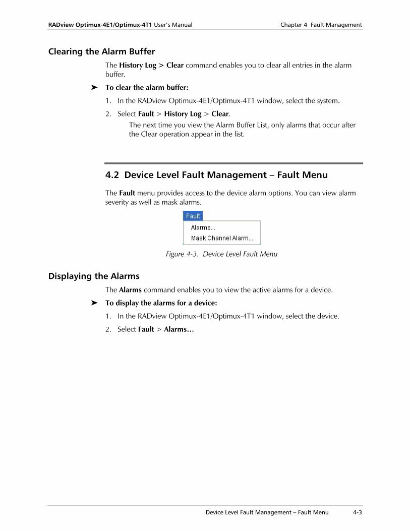
The Fault menu provides access to the device alarm options. You can view alarm severity as well as mask alarms.
Figure 4-3. Device Level Fault Menu
Displaying the Alarms The Alarms command enables you to view the active alarms for a device.
To display the alarms for a device:
1. In the RADview Optimux-4E1/Optimux-4T1 window, select the device.
2. Select Fault > Alarms…
Chapter 4 Fault Management RADview Optimux-4E1/Optimux-4T1 User’s Manual
4-4 Device Level Fault Management – Fault Menu
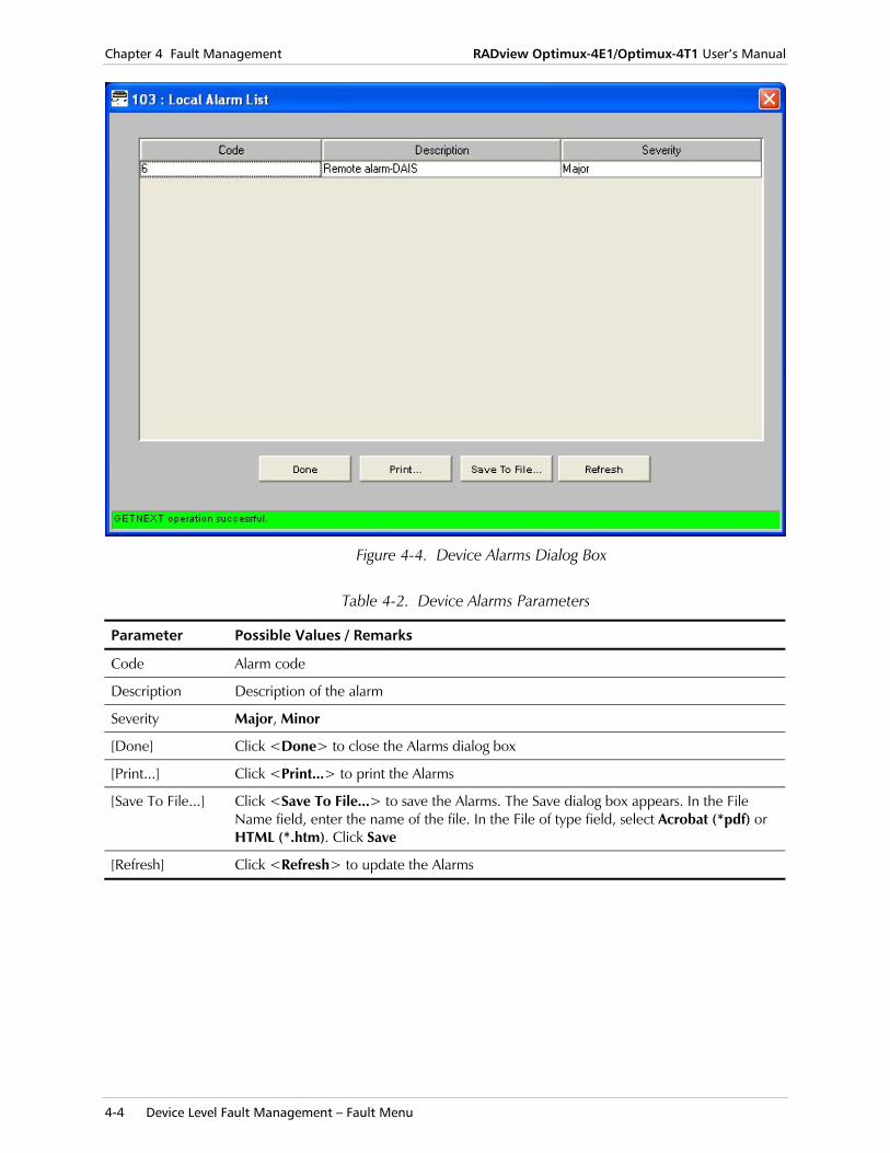
Figure 4-4. Device Alarms Dialog Box
Table 4-2. Device Alarms Parameters
Parameter Possible Values / Remarks
Code Alarm code
Description Description of the alarm
Severity Major, Minor
[Done] Click <Done> to close the Alarms dialog box
[Print...] Click <Print...> to print the Alarms
[Save To File...] Click <Save To File...> to save the Alarms. The Save dialog box appears. In the File Name field, enter the name of the file. In the File of type field, select Acrobat (*pdf) or HTML (*.htm). Click Save
[Refresh] Click <Refresh> to update the Alarms
RADview Optimux-4E1/Optimux-4T1 User’s Manual Chapter 4 Fault Management
Device Level Fault Management – Fault Menu 4-5
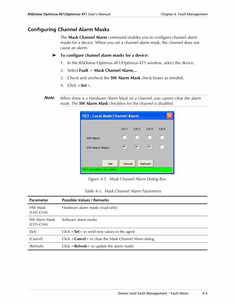
Configuring Channel Alarm Masks The Mask Channel Alarm command enables you to configure channel alarm masks for a device. When you set a channel alarm mask, the channel does not cause an alarm.
To configure channel alarm masks for a device:
1. In the RADview Optimux-4E1/Optimux-4T1 window, select the device.
2. Select Fault > Mask Channel Alarm…
3. Check and uncheck the SW Alarm Mask check boxes as needed.
4. Click <Set>.
When there is a Hardware Alarm Mask on a channel, you cannot clear the alarm mask. The SW Alarm Mask checkbox for the channel is disabled.
Figure 4-5. Mask Channel Alarm Dialog Box
Table 4-3. Mask Channel Alarm Parameters
Parameter Possible Values / Remarks
HW Mask (CH1-CH4)
Hardware alarm masks (read-only)
SW Alarm Mask (CH1-CH4)
Software alarm masks
[Set] Click <Set> to send new values to the agent
[Cancel] Click <Cancel> to close the Mask Channel Alarm dialog.
[Refresh] Click <Refresh> to update the alarm masks
Note
Chapter 4 Fault Management RADview Optimux-4E1/Optimux-4T1 User’s Manual
4-6 Device Level Fault Management – Diagnostics Menu
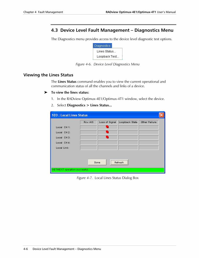
4.3 Device Level Fault Management – Diagnostics Menu
The Diagnostics menu provides access to the device level diagnostic test options.
Figure 4-6. Device Level Diagnostics Menu
Viewing the Lines Status The Lines Status command enables you to view the current operational and communication status of all the channels and links of a device.
To view the lines status:
1. In the RADview Optimux-4E1/Optimux-4T1 window, select the device.
2. Select Diagnostics > Lines Status...
Figure 4-7. Local Lines Status Dialog Box
RADview Optimux-4E1/Optimux-4T1 User’s Manual Chapter 4 Fault Management
Device Level Fault Management – Diagnostics Menu 4-7
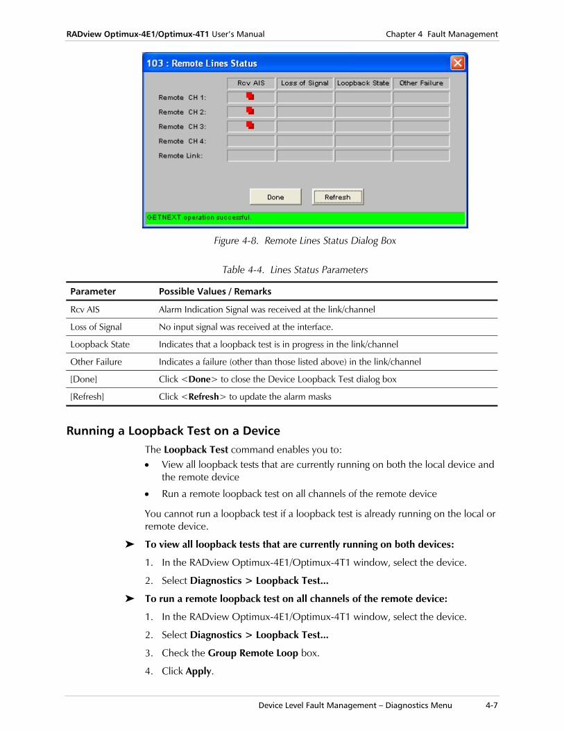
Figure 4-8. Remote Lines Status Dialog Box
Table 4-4. Lines Status Parameters
Parameter Possible Values / Remarks
Rcv AIS Alarm Indication Signal was received at the link/channel
Loss of Signal No input signal was received at the interface.
Loopback State Indicates that a loopback test is in progress in the link/channel
Other Failure Indicates a failure (other than those listed above) in the link/channel
[Done] Click <Done> to close the Device Loopback Test dialog box
[Refresh] Click <Refresh> to update the alarm masks
Running a Loopback Test on a Device The Loopback Test command enables you to: • View all loopback tests that are currently running on both the local device and
the remote device
• Run a remote loopback test on all channels of the remote device
You cannot run a loopback test if a loopback test is already running on the local or remote device.
To view all loopback tests that are currently running on both devices:
1. In the RADview Optimux-4E1/Optimux-4T1 window, select the device.
2. Select Diagnostics > Loopback Test...
To run a remote loopback test on all channels of the remote device:
1. In the RADview Optimux-4E1/Optimux-4T1 window, select the device.
2. Select Diagnostics > Loopback Test...
3. Check the Group Remote Loop box.
4. Click Apply.
Chapter 4 Fault Management RADview Optimux-4E1/Optimux-4T1 User’s Manual
4-8 Port Level Fault Management – Fault Menu
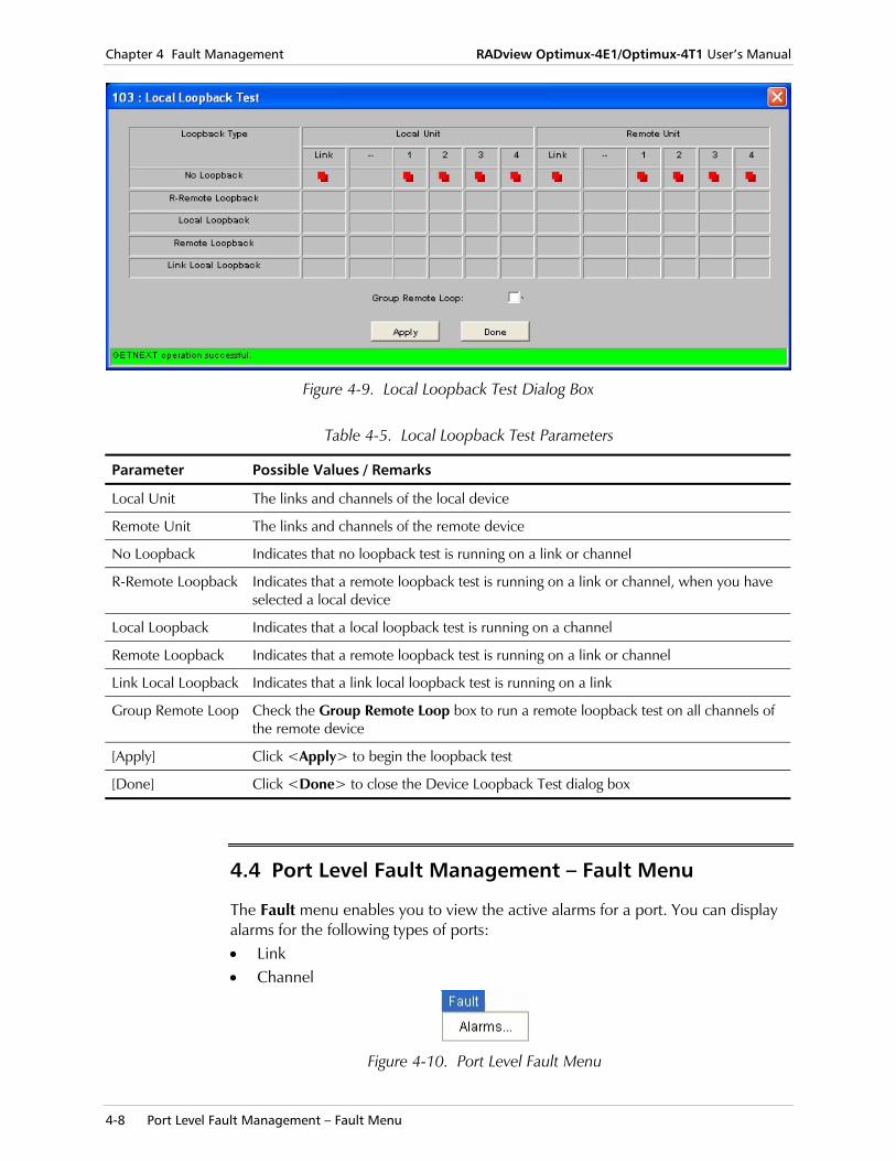
Figure 4-9. Local Loopback Test Dialog Box
Table 4-5. Local Loopback Test Parameters
Parameter Possible Values / Remarks
Local Unit The links and channels of the local device
Remote Unit The links and channels of the remote device
No Loopback Indicates that no loopback test is running on a link or channel
R-Remote Loopback Indicates that a remote loopback test is running on a link or channel, when you have selected a local device
Local Loopback Indicates that a local loopback test is running on a channel
Remote Loopback Indicates that a remote loopback test is running on a link or channel
Link Local Loopback Indicates that a link local loopback test is running on a link
Group Remote Loop Check the Group Remote Loop box to run a remote loopback test on all channels of the remote device
[Apply] Click <Apply> to begin the loopback test
[Done] Click <Done> to close the Device Loopback Test dialog box
4.4 Port Level Fault Management – Fault Menu
The Fault menu enables you to view the active alarms for a port. You can display alarms for the following types of ports: • Link • Channel
Figure 4-10. Port Level Fault Menu
RADview Optimux-4E1/Optimux-4T1 User’s Manual Chapter 4 Fault Management
Port Level Fault Management – Fault Menu 4-9
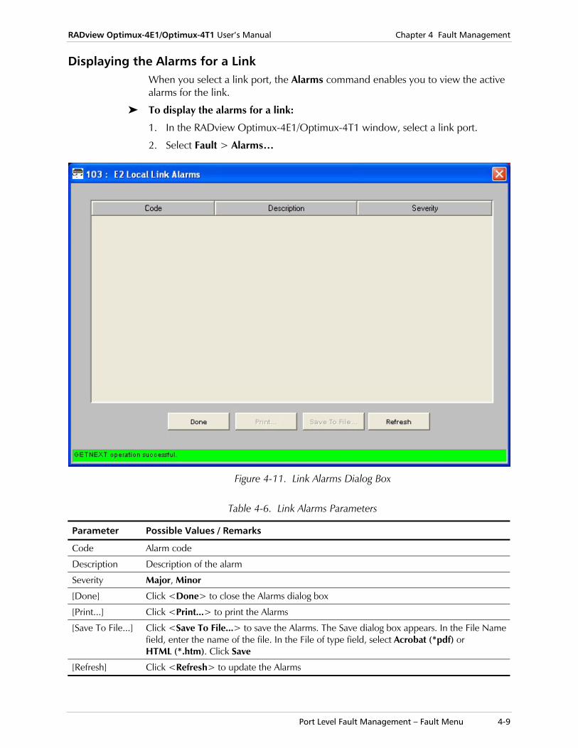
Displaying the Alarms for a Link When you select a link port, the Alarms command enables you to view the active alarms for the link.
To display the alarms for a link:
1. In the RADview Optimux-4E1/Optimux-4T1 window, select a link port.
2. Select Fault > Alarms…
Figure 4-11. Link Alarms Dialog Box
Table 4-6. Link Alarms Parameters
Parameter Possible Values / Remarks
Code Alarm code
Description Description of the alarm
Severity Major, Minor
[Done] Click <Done> to close the Alarms dialog box
[Print...] Click <Print...> to print the Alarms
[Save To File...] Click <Save To File...> to save the Alarms. The Save dialog box appears. In the File Name field, enter the name of the file. In the File of type field, select Acrobat (*pdf) or HTML (*.htm). Click Save
[Refresh] Click <Refresh> to update the Alarms
Chapter 4 Fault Management RADview Optimux-4E1/Optimux-4T1 User’s Manual
4-10 Port Level Fault Management – Fault Menu
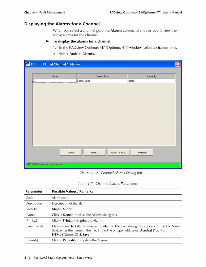
Displaying the Alarms for a Channel When you select a channel port, the Alarms command enables you to view the active alarms for the channel.
To display the alarms for a channel:
1. In the RADview Optimux-4E1/Optimux-4T1 window, select a channel port.
2. Select Fault > Alarms…
Figure 4-12. Channel Alarms Dialog Box
Table 4-7. Channel Alarms Parameters
Parameter Possible Values / Remarks
Code Alarm code
Description Description of the alarm
Severity Major, Minor
[Done] Click <Done> to close the Alarms dialog box
[Print...] Click <Print...> to print the Alarms
[Save To File...] Click <Save To File...> to save the Alarms. The Save dialog box appears. In the File Name field, enter the name of the file. In the File of type field, select Acrobat (*pdf) or HTML (*.htm). Click Save
[Refresh] Click <Refresh> to update the Alarms
RADview Optimux-4E1/Optimux-4T1 User’s Manual Chapter 4 Fault Management
Port Level Fault Management – Diagnostics Menu 4-11
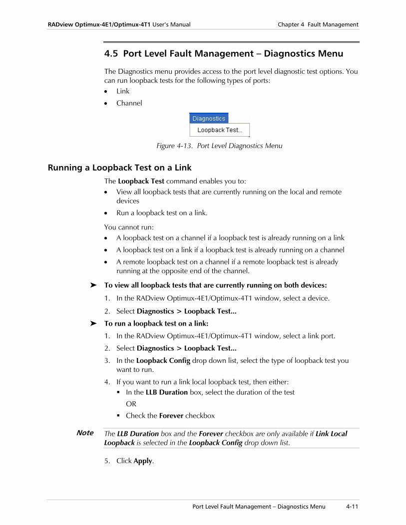
4.5 Port Level Fault Management – Diagnostics Menu
The Diagnostics menu provides access to the port level diagnostic test options. You can run loopback tests for the following types of ports: • Link
• Channel
Figure 4-13. Port Level Diagnostics Menu
Running a Loopback Test on a Link The Loopback Test command enables you to: • View all loopback tests that are currently running on the local and remote
devices
• Run a loopback test on a link.
You cannot run: • A loopback test on a channel if a loopback test is already running on a link
• A loopback test on a link if a loopback test is already running on a channel
• A remote loopback test on a channel if a remote loopback test is already running at the opposite end of the channel.
To view all loopback tests that are currently running on both devices:
1. In the RADview Optimux-4E1/Optimux-4T1 window, select a device.
2. Select Diagnostics > Loopback Test...
To run a loopback test on a link:
1. In the RADview Optimux-4E1/Optimux-4T1 window, select a link port.
2. Select Diagnostics > Loopback Test...
3. In the Loopback Config drop down list, select the type of loopback test you want to run.
4. If you want to run a link local loopback test, then either: In the LLB Duration box, select the duration of the test
OR
Check the Forever checkbox
The LLB Duration box and the Forever checkbox are only available if Link Local Loopback is selected in the Loopback Config drop down list.
5. Click Apply.
Note
Chapter 4 Fault Management RADview Optimux-4E1/Optimux-4T1 User’s Manual
4-12 Port Level Fault Management – Diagnostics Menu
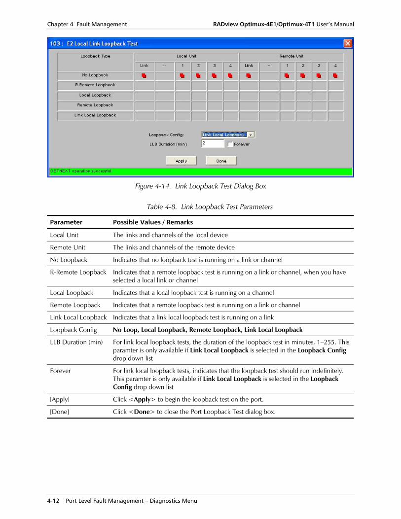
Figure 4-14. Link Loopback Test Dialog Box
Table 4-8. Link Loopback Test Parameters
Parameter Possible Values / Remarks
Local Unit The links and channels of the local device
Remote Unit The links and channels of the remote device
No Loopback Indicates that no loopback test is running on a link or channel
R-Remote Loopback Indicates that a remote loopback test is running on a link or channel, when you have selected a local link or channel
Local Loopback Indicates that a local loopback test is running on a channel
Remote Loopback Indicates that a remote loopback test is running on a link or channel
Link Local Loopback Indicates that a link local loopback test is running on a link
Loopback Config No Loop, Local Loopback, Remote Loopback, Link Local Loopback
LLB Duration (min) For link local loopback tests, the duration of the loopback test in minutes, 1–255. This paramter is only available if Link Local Loopback is selected in the Loopback Config drop down list
Forever For link local loopback tests, indicates that the loopback test should run indefinitely. This paramter is only available if Link Local Loopback is selected in the Loopback Config drop down list
[Apply] Click <Apply> to begin the loopback test on the port.
[Done] Click <Done> to close the Port Loopback Test dialog box.
RADview Optimux-4E1/Optimux-4T1 User’s Manual Chapter 4 Fault Management
Port Level Fault Management – Diagnostics Menu 4-13
Running a Loopback Test on a Channel The Loopback Test command enables you to:
• View all loopback tests that are currently running on the local and remote devices
• Run a loopback test on a channel.
You cannot run:
• A loopback test on a channel if a loopback test is already running on a link
• A loopback test on a link if a loopback test is already running on a channel
• A remote loopback test on a channel if a remote loopback test is already running at the opposite end of the channel.
To view all loopback tests that are currently running on both devices:
1. In the RADview Optimux-4E1/Optimux-4T1 window, select a device.
2. Select Diagnostics > Loopback Test...
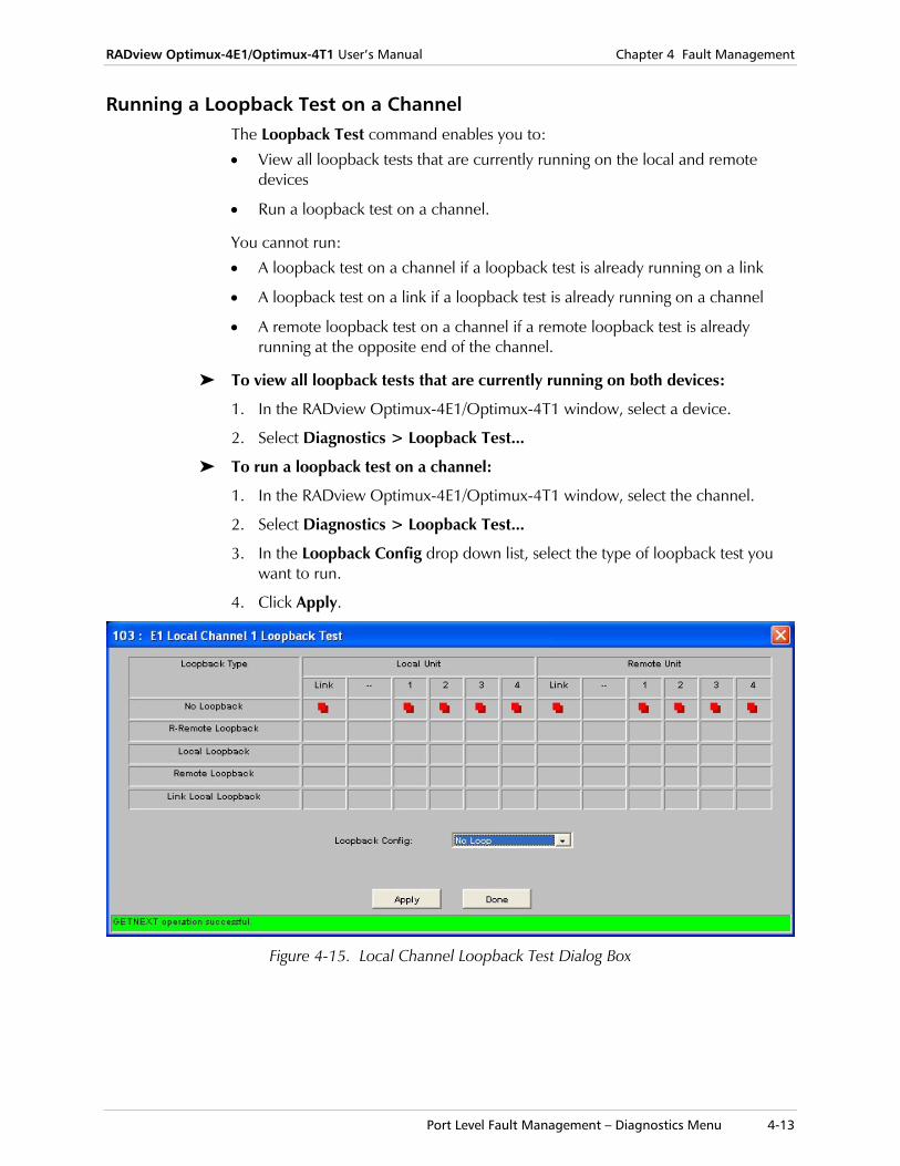
To run a loopback test on a channel:
1. In the RADview Optimux-4E1/Optimux-4T1 window, select the channel.
2. Select Diagnostics > Loopback Test...
3. In the Loopback Config drop down list, select the type of loopback test you want to run.
4. Click Apply.
Figure 4-15. Local Channel Loopback Test Dialog Box
Chapter 4 Fault Management RADview Optimux-4E1/Optimux-4T1 User’s Manual
4-14 Port Level Fault Management – Diagnostics Menu
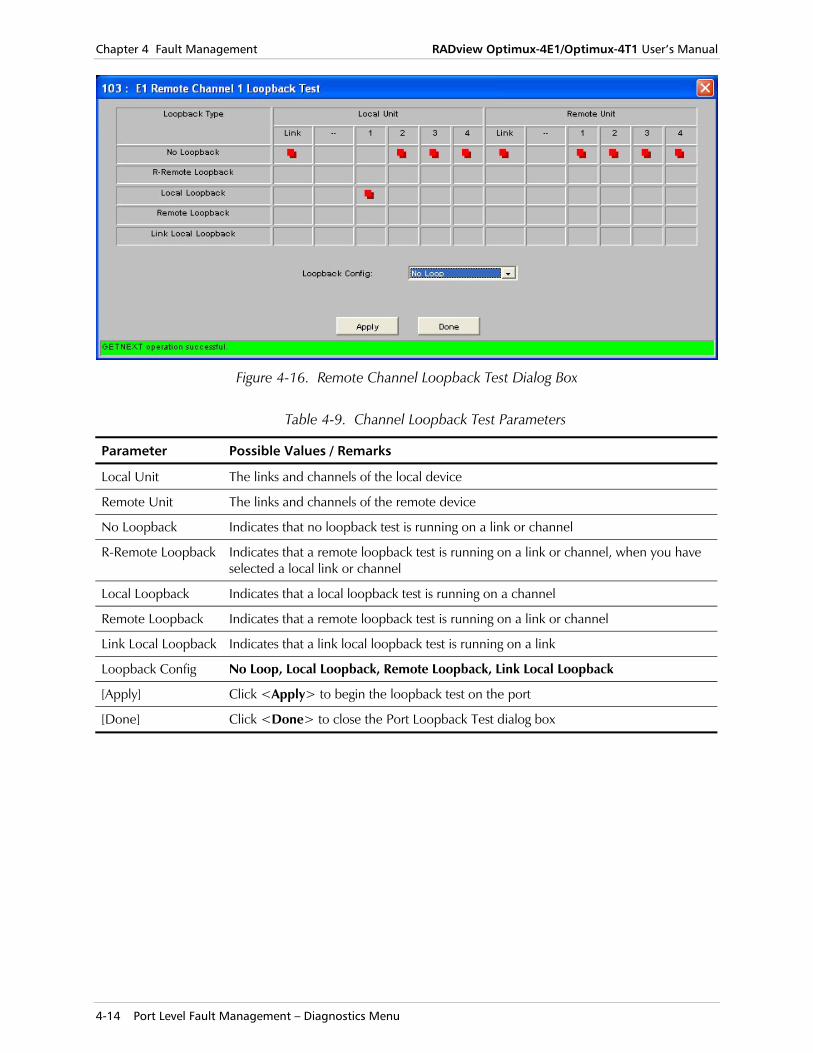
Figure 4-16. Remote Channel Loopback Test Dialog Box
Table 4-9. Channel Loopback Test Parameters
Parameter Possible Values / Remarks
Local Unit The links and channels of the local device
Remote Unit The links and channels of the remote device
No Loopback Indicates that no loopback test is running on a link or channel
R-Remote Loopback Indicates that a remote loopback test is running on a link or channel, when you have selected a local link or channel
Local Loopback Indicates that a local loopback test is running on a channel
Remote Loopback Indicates that a remote loopback test is running on a link or channel
Link Local Loopback Indicates that a link local loopback test is running on a link
Loopback Config No Loop, Local Loopback, Remote Loopback, Link Local Loopback
[Apply] Click <Apply> to begin the loopback test on the port
[Done] Click <Done> to close the Port Loopback Test dialog box

I-1
Index
—A— Access restrictions, 3-5 Agents, polling, 3-3
—C— Channel
parameters, 3-12 Communities
read community, 2-2 trap community, 2-2 write community, 2-2
Configuration device level, 3-6 overview, 3-1 port level, 3-10 resetting, 3-9 system level, 3-1
Configuring access, 3-5 channel parameters, 3-12 device parameters, 3-6 link parameters, 3-10 manager list, 3-3 polling, 3-6 system information, 3-1
Control Port configuring, 2-4, 2-5
—D— Device
configuring parameters, 3-6 interface information, 3-8 LEDs, 2-7 management, 2-8
Device level configuration, 3-6 operations, 2-8
Device mode management options, 2-8
—G— Graphical user interface, 2-5
—H— Hardware, resetting, 3-9
—I— Interface information, 3-8
—L— LEDs, 2-7 Link
parameters, 3-10
—M— Management Access
setting, 2-2 Management options
device mode, 2-8 port mode, 2-9 system mode, 2-7
Manager List, 3-3 setting, 2-2
Managing configuration, 3-1
Menu Host IP List, 2-1 Manager Access, 2-3 Telnet, 2-3
Menu bar, 2-6
—O— Operations
device level, 2-8 port level, 2-9 system level, 2-7
Options, system level, 3-3
—P— Parameters
channel, 3-12 device, 3-6 link, 3-10
Polling agents, 3-3 configuring, 3-6
Port management, 2-9
Port level configuration, 3-10 operations, 2-9
Port mode management options, 2-9
—R— Resetting
configuration, 3-9
Index RADview Optimux-4E1/Optimux-4T1 Network Management Software Guide
I-2
hardware, 3-9
—S— Screen
Manager List, 2-2 Setting
channel parameters, 3-12 device parameters, 3-6 link parameters, 3-10 system information, 3-1
Status bar, 2-6 System
management, 2-7 setting system information, 3-1 viewing system information, 3-1
System level configuration, 3-1 operations, 2-7 options, 3-3
System mode management options, 2-7
—U— Using
graphical user interface, 2-5 menu bar, 2-6
—V— Viewing
access, 3-5 channel parameters, 3-12 device parameters, 3-6 interface information, 3-8 LEDs, 2-7 link parameters, 3-10 manager list, 3-3 status bar, 2-6 system information, 3-1