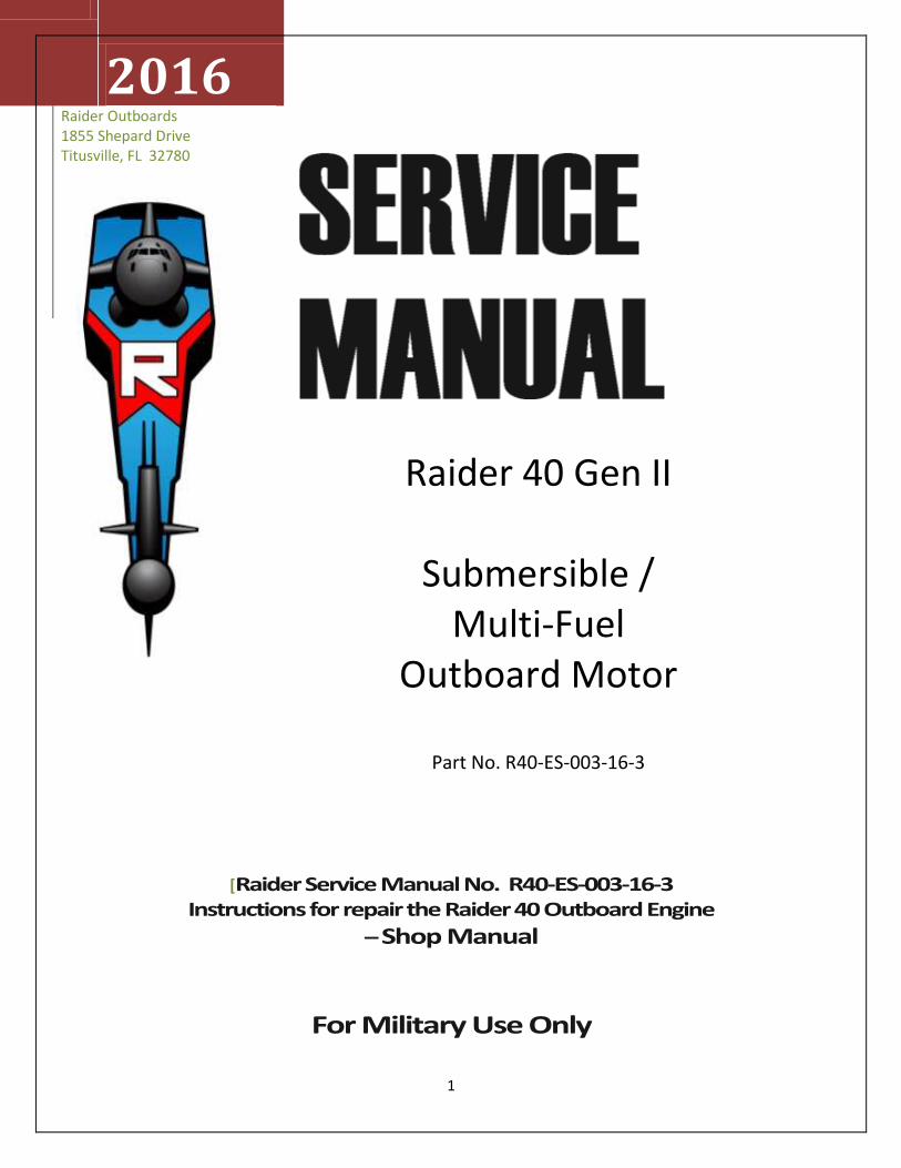
raider 40 gen ii submersible / multi-fuel outboard motor
TRANSCRIPT
1
2016 Raider Outboards
1855 Shepard Drive Titusville, FL 32780
[Raider Service Manual No. R40-ES-003-16-3 Instructions for repair the Raider 40 Outboard Engine
– Shop Manual
For Military Use Only
Raider 40 Gen II
Submersible / Multi-Fuel
Outboard Motor
Part No. R40-ES-003-16-3
2
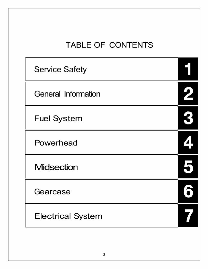
TABLE OF CONTENTS
Service Safety
General Information
Fuel System
Powerhead
Midsection
Gearcase
Electrical System
3
TABLE OF CONTENTS
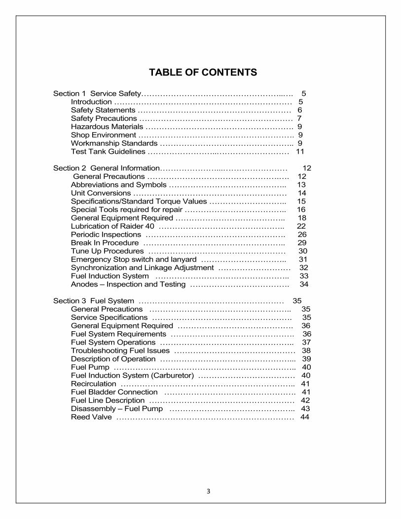
Section 1 Service Safety……………………………………………..…. 5 Introduction ………………………………………………………… 5 Safety Statements ………………………………………………… 6 Safety Precautions ………………………………………………… 7 Hazardous Materials ………………………………………………. 9 Shop Environment …………………………………………………. 9 Workmanship Standards ………………………………………….. 9 Test Tank Guidelines ……………………..……………………… 11 Section 2 General Information…………………...…………………… 12 General Precautions ………………………………………….…. 12 Abbreviations and Symbols …………………………………….. 13 Unit Conversions ………………………………………………… 14 Specifications/Standard Torque Values ……………………….. 15 Special Tools required for repair ……………………………….. 16 General Equipment Required ………………………………….. 18 Lubrication of Raider 40 ……………………………………….. 22 Periodic Inspections ……………………………………………. 26 Break In Procedure …………………………………………….. 29 Tune Up Procedures …………………………………………… 30 Emergency Stop switch and lanyard ………………………….. 31 Synchronization and Linkage Adjustment ……………………… 32 Fuel Induction System ………………………………………….. 33 Anodes – Inspection and Testing ………………………………. 34 Section 3 Fuel System ……………………………………………… 35 General Precautions …………………………………………….. 35 Service Specifications ……………………………………………. 35 General Equipment Required ……………………………………. 36 Fuel System Requirements ………………………………………. 36 Fuel System Operations ………………………………………….. 37 Troubleshooting Fuel Issues ……………………………………… 38 Description of Operation …………………………………………... 39 Fuel Pump ………………………………………………………….. 40 Fuel Induction System (Carburetor) ……………………………… 40 Recirculation ……………………………………………………….. 41 Fuel Bladder Connection …………………………………………. 41 Fuel Line Description ……………………………………………… 42 Disassembly – Fuel Pump ……………………………………….. 43 Reed Valve ………………………………………………………… 44

4
Section 4 Powerhead ……………………………………………….47 General Precautions ……………………………………………. 47 Service Specifications ………………………………………….. 47 Manufacturers Special Tools Required ………………………. 48 General Equipment Requirements ……………………………. 48 Consumables ……………………………………………………. 48 Troubleshooting Powerhead ……………………………………. 49 Description of Operation ………………………………………… 50 Thermostat ………………………………………………………… 51 RPM Performance Test …………………………………………. 52 Recoil Starter ……………………………………………………… 53 Pull Start Diagram ………………………………………………… 55 Flywheel …………………………………………………………… 56 Raider Engine Block Diagram ……………………………………. 58 Removal of Raider Engine ……………………………………….. 59 Disassembly of Raider Powerhead ……………………………… 61 Assembly of Raider Powerhead …………………………………. 71 Section 5 Midsection …………………………………………………. 77 General Precautions ……………………………………………… 77 Service Specifications ……………………………………………. 77 General Equipment Required ……………………………………. 77 Consumables Supplies Required ………………………………… 78 Tiller Steering Handle ……………………………………………… 78 Handle and Linkage ……………………………………………….. 81 Lower Engine Cover ………………………………………………. 88 Driveshaft Housing …………………………………………………. 89 Stern Bracket ……………………………………………………….. 94 Swivel Bracket and Reverse Lock ………………………………… 95 Section 6 Gearcase ……………………………………………………. 96 General Precautions ……………………………………………….. 96 Service Specifications ……………………………………………… 96 Special Equipment Required ……………………………………… 97 General Equipment Required …………………………………….. 98 Consumables Required …………………………………………… 98 Waterpump …………………………………………………………. 98 Gearcase ……………………………………………………… 103 Backlash ……………………………………………………… 115 Gearcase Repair Procedures …………………………………119 Section 7 Electrical System …………………………………………….. 123 General Precautions ……………………………………………….. 123 Service Specifications …………………………………………….. 124 Electrical Servicing Standards …………………………………….. 124 Troubleshooting ……………………………………………………. 127 Description of Operation …………………………………………… 129 Battery Care and Maintenance ……………………………………. 132 Ignition System ……………………………………………………… 147 Ignition System Repair Procedures ……………………………….. 163 Starting System …………………………………………………….. 171

5
SECTION 1 - SERVICE SAFETY
Inadequate knowledge of safe shop practices can result in severe injury or death. Review general safety procedures and specific safety information provided for each procedure prior to beginning any repairs.
INTRODUCTION Raider outboards is required to comply with special EPA regulations and standards to ensure your military products are safe and reliable. As the military technician, it is your responsibility to keep these products safe when performing normal repair and maintenance operations.
It is not possible to foresee all safety hazards which may occur or to include all the knowledge of an experienced technician in a single service manual. Therefore, it is assumed those using this manual have a working knowledge of 2-cycle outboard engines and the proper technical training for servicing. Raider outboards is considered a Commercial Off The Shelf (COTS) outboard engine. The engine comes from a family of engines: Mercury, Nissan and Tohatsu.
This section discusses safe shop practices and general safety concerns relevant to the operations performed throughout this manual. Read this section carefully and follow all safety statements in this manual as they pertain to the procedures at hand. Remember, always use common sense when servicing outboard engines! Raider supports three manuals for Generation II Outboards: Owner/Operators Gen II Manual; R40-ES-001-16-1; Parts and Assembly Gen II Manual: R40-ES-001-16-2 which has all part numbers and assembly information; and Raider Gen II Service Manual R40-ES-001-16-3 that provides complete information to repair the Raider 40 Generation II outboard motor.
KC-5030
6
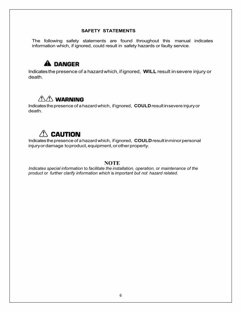
SAFETY STATEMENTS The following safety statements are found throughout this manual indicates information which, if ignored, could result in safety hazards or faulty service.
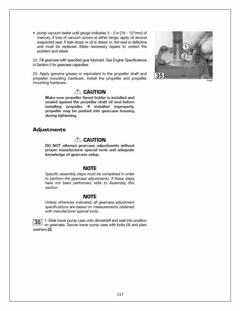
Indicates the presence of a hazard which, if ignored, WILL result in severe injury or death.
Indicates the presence of a hazard which, if ignored, COULD result in severe injury or
death.
Indicates the presence of a hazard which, if ignored, COULD result in minor personal
injury or damage to product, equipment, or other property.
NOTE Indicates special information to facilitate the installation, operation, or maintenance of the product or further clarify information which is important but not hazard related.

7
SAFETY PRECAUTIONS
Raider Outboard Engines
Never disable the neutral switch start-in-gear prevention system. Always test the neutral switch and emergency stop switch before returning an engine to the user.
Lifting devices and hardware must be of suitable capacity for the weight of the outboard engine. Be aware the engine may swing outward when lifted.
The Raider engine stand must be in good condition; Raider engine must be mounted properly to prevent unexpected shifting.
Engine covers (cowling) are guards to prevent personal contact with the spinning flywheel and high voltage components such as spark plugs and coils. Never wear jewelry or loose clothing near a running engine. Keep hands, arms and hair away from the flywheel. Never touch electrical
components when the engine is running. Two people working on a running engine must use extreme caution and be aware of one another. Never attempt to start
an engine or operate any controls before signaling your partner. To prevent accidental startup during operations which may cause the flywheel to turn, always perform the following steps:
1. Insure battery is disconnected or removed. 2. Disable the engine ignition system. 3. Shift engine to NEUTRAL and verify propeller shaft is
not in gear. Rotating propellers are not equipped with guards and can cause severe injury or dismemberment. Always stay clear of rotating propellers and make sure there is no possibility of engine startup before removing or installing a propeller. The propeller nut must always be tightened to torque specification prior to starting the engine.
Raider Start Button
8
Additional Safety Precautions
Avoid running the engine at high RPM. Engine speed can easily increase to excessive RPM when under a no load condition. To avoid engine damage during testing, always use the correct test propeller and keep engine speed below 2000 RPM.
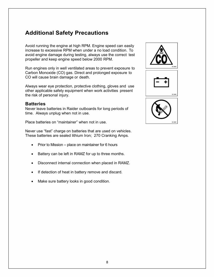
Run engines only in well ventilated areas to prevent exposure to Carbon Monoxide (CO) gas. Direct and prolonged exposure to CO will cause brain damage or death. Always wear eye protection, protective clothing, gloves and use other applicable safety equipment when work activities present the risk of personal injury.
Batteries Never leave batteries in Raider outboards for long periods of time. Always unplug when not in use. Place batteries on “maintainer” when not in use. Never use “fast” charge on batteries that are used on vehicles. These batteries are sealed lithium Iron; 270 Cranking Amps.
Prior to Mission – place on maintainer for 6 hours
Battery can be left in RAMZ for up to three months.
Disconnect internal connection when placed in RAMZ.
If detection of heat in battery remove and discard.
Make sure battery looks in good condition.
KC-5032
KC-4080
KC-5050
9
Hazardous Materials
Gasoline vapors are highly flammable and can cause an explosion. Never smoke or allow sparks or flames nearby when handling fuel Always store gasoline in a shaded, well ventilated area in an approved safety container. Heavy Fuels that can be burned in the Raider 40 have
harmful fumes that must be considered hazardous. Wear masks. Ventilate all fumes as soon as detected. Be aware that
appliance pilot lights, such as those in furnaces and water heaters, can ignite gasoline vapors and cause explosion. Never use gasoline as a cleaner, and always clean up fuel spills immediately and properly dispose of rags in an approved safety container. Read and follow the safety labels on products used around the shop. Adhesives, lubricants, solvents, and fuel additives are usually poisonous and flammable. Store and dispose of these products properly.
Shop Environment Make sure the shop and your work area are properly ventilated. Shops must be equipped with the proper tools and safety equipment such as fire extinguisher, eye flushing device, and first aid kit. Keep the shop clean and free of clutter. Clean up spills on the floor as soon as possible to prevent someone from slipping.
WORKMANSHIP STANDARDS 1. Avoid damage to the mating surfaces of crankcase and
cylinder assembly. Do not use a sharp metal scraper to clean these areas.
2. Replace gaskets, 0-rings, seals, cotter pins, lock nuts, and spring pins when removed during repair operations.
3. Use only genuine factory replacement parts and
accessories. 4. Use recommended special tools when specific repairs
require them. 5. Calibrate measurement tools and test equipment on a
regular basis. 6. Clean all metal parts with solvent before inspection and
assembly operations. 7. Use penetrating solvents when necessary to remove
rusted or seized hardware.
10
8. Keep all removed parts separated for ease of identification during assembly.
9. Locate alignment marks on components being
disassembled. If marks are not present and should
be, scribe or match mark them yourself to ensure the
pieces are assembled properly.
10. Follow torque sequences and specifications where
they apply. First, tighten each bolt in the specified
sequence. Use the same sequence to torque each
bolt to final specification. Special torque specifications
are listed at the beginning of each section. Standard
torque specifications for common fasteners are listed
in Section 3.
11. Use lubricant when assembling seals to prevent
damage to the seal lips. Make sure seal lips are facing
the correct direction.
12. Use the correct type and amount of sealing compound
on metal to metal surfaces.
13. When using compressed air to clean or dry parts,
make sure air supply is regulated not to exceed 25 psi
[172 kPa /1.76 kg/cm'].
14. Replace missing or damaged safety labels on the
engine before returning it to the user.
NOTE: Throughout this manual “genuine” oil if used. This oil is the Raider Outboard two-stroke oil; however, any TC-W3 approved oil can be substituted and used.
11
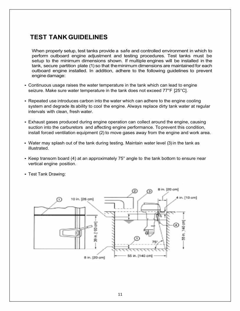
TEST TANK GUIDELINES
When properly setup, test tanks provide a safe and controlled environment in which to perform outboard engine adjustment and testing procedures. Test tanks must be setup to the minimum dimensions shown. If multiple engines will be installed in the tank, secure partition plate (1) so that the minimum dimensions are maintained for each outboard engine installed. In addition, adhere to the following guidelines to prevent engine damage:
• Continuous usage raises the water temperature in the tank which can lead to engine
seizure. Make sure water temperature in the tank does not exceed 77°F [25°C].
• Repeated use introduces carbon into the water which can adhere to the engine cooling
system and degrade its ability to cool the engine. Always replace dirty tank water at regular
intervals with clean, fresh water.
• Exhaust gases produced during engine operation can collect around the engine, causing
suction into the carburetors and affecting engine performance. To prevent this condition,
install forced ventilation equipment (2) to move gases away from the engine and work area.
• Water may splash out of the tank during testing. Maintain water level (3) in the tank as
illustrated.
• Keep transom board (4) at an approximately 75° angle to the tank bottom to ensure near
vertical engine position.
• Test Tank Drawing:
12
SECTION 2 – General Information
General Precautions
Before performing any service work on the outboard engine, read and understand Section 1 - Service Safety.
Use only genuine factory replacement parts with equivalent characteristics such as type, material, and strength. Failure to do so may result in product malfunction and injury to the operator or
passengers. Follow the Standard Torque Values chart. When a special torque value for a certain fastener is not listed in the Special Torque Values chart at the beginning of each section tighten using the Standard Torque Values chart.
Rather than just repairing a bad part, use repair kits and overhaul kits when applicable to ensure
complete and efficient repair of the complete component. Wear not readily noticed on other parts can
lead to malfunction soon after the repair .
When indicated in a procedure, use manufacturer special tools. In some cases, the use of substitute tools
will damage the part.
When using compressed air to clean or dry parts, make sure air supply is regulated not to exceed 25 psi
[172 kPa / 1.76 kg/cm'].
13
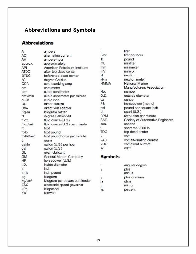
Abbreviations and Symbols
14
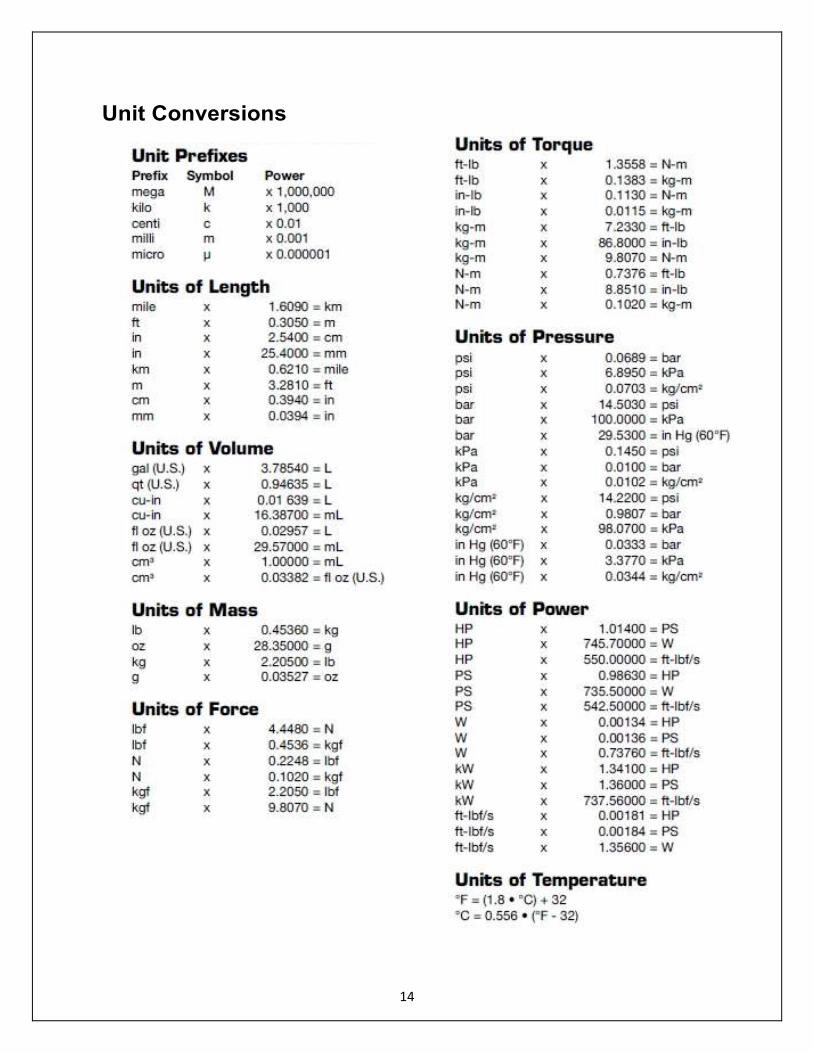
Unit Conversions
15
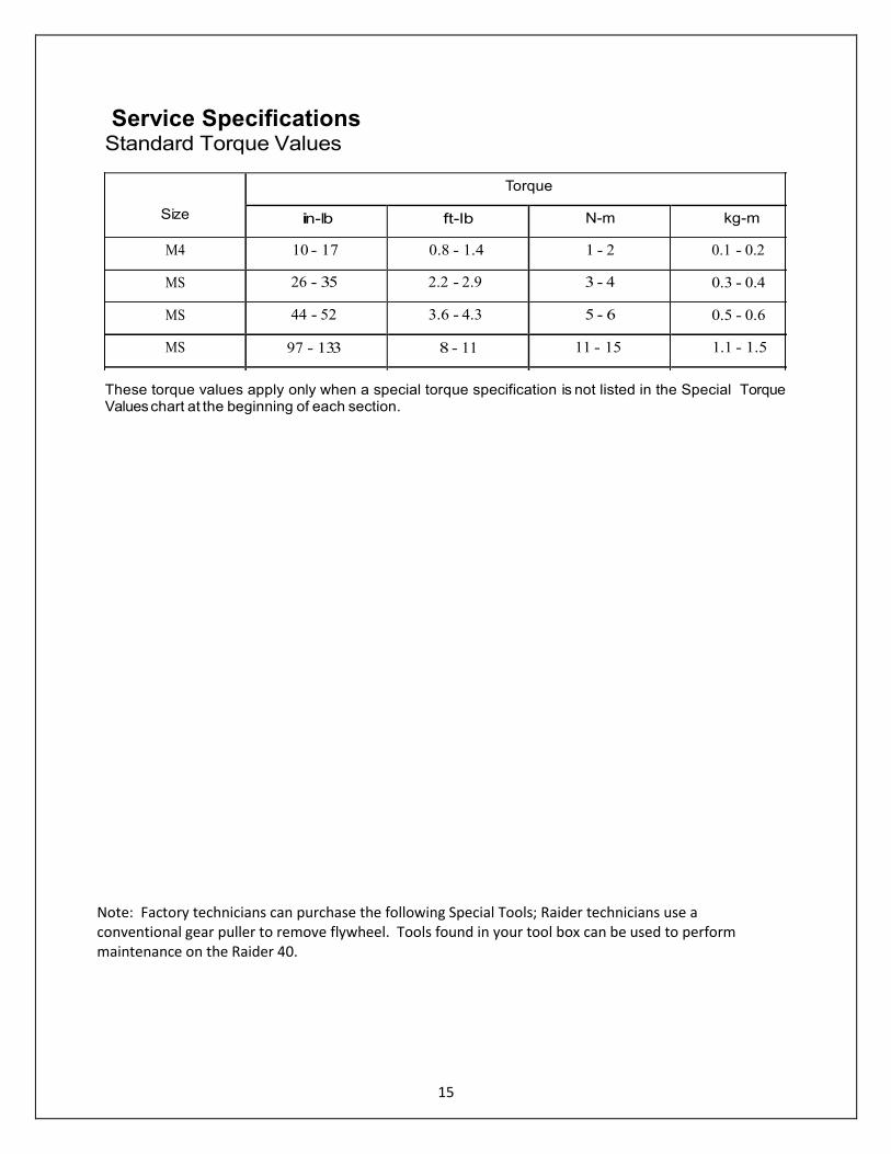
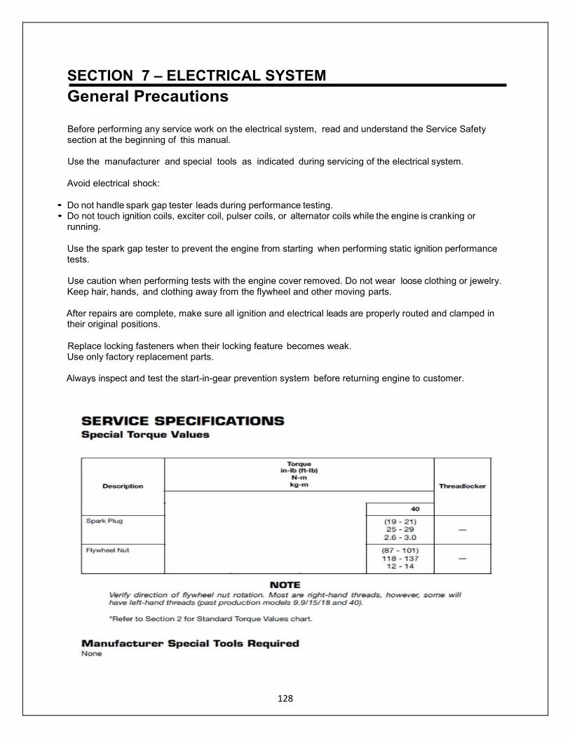
Service Specifications Standard Torque Values
These torque values apply only when a special torque specification is not listed in the Special Torque Values chart at the beginning of each section.
Size
Torque
in-lb ft-lb N-m kg-m
M4 10 - 17 0.8 - 1.4 1 - 2 0.1 - 0.2
MS 26 - 35 2.2 - 2.9 3 - 4 0.3 - 0.4
MS 44 - 52 3.6 - 4.3 5 - 6 0.5 - 0.6
MS 97 - 133 8 - 11 11 - 15 1.1 - 1.5
M10 204 - 274 17 - 22 23 - 31 2.3 - 3.1
Note: Factory technicians can purchase the following Special Tools; Raider technicians use a conventional gear puller to remove flywheel. Tools found in your tool box can be used to perform maintenance on the Raider 40.
16
Special Tools for Repair – Raider 40
17
Continued - Raider 40
18
General Equipment Required
19
Consumables Required Threadlocker, Loctite 242 Threadlocker, Loctite 243 Gasket Dressing, Permatex Hylomar Aerosol High-Temp Gasket Dressing Gasket Sealant, Permatex High Tack Gasket Sealant Anaerobic Gasket Maker, Loctite 518 Silicone Sealant, Permatex" Hi-Temp RTV Silicone Gasket Super Bond Adhesive, Permatex
Super Glue Gel Cleaning Pads, Scotch-Brite Abrasive Pads
Low Temperature Lithium Grease Genuine Grease or Equivalent Friction Surface Marine Grease isopropyl Alcohol Cleaning Solvent Gasket Remover
Gear Lubricant, Genuine gear oil or AP/ grade GLS, SAE #80 - #90 Engine Lubricant,
Genuine engine oil or NMMA certified TC-W3 oil Automotive Crankcase Oil, flashpoint
above 300'F [150°C]
Battery Spray Protector, Permatex Battery Protector & Sealer Electrical Shrink Tubing, various diameters Form-A-Gasket, Permatex (Aviation Sealant Liquid) – Head Gasket Corrosion Zero – anti-corrosion spray can
20
Section 2
Raider 40 Specifications Operational
Power Raider ................................40 HP [29.4 kW]
Full Throttle RPM Range Raider .....................................5200 - 5800
Idle RPM In Gear Neutral Raider ……………………………..850 1000 Fuel Consumption at Full Throttle Raider ................................ 4.0 g/hr
Multiple Fuels Gasoline – primary – Heavy Fuel Optional
JP-5/8; Kerosene; Diesel; Bio-diesel]
Submersible – special dewatering 66 feet underwater/18 hours – start 5 min.
Crankshaft Dimensions
Dimension 1
Raider 40 .................2.071 + 0 in [52.6 + 0 mm] - 0.002 - 0.05
Dimension 2 Raider 40 .............. 1.591 ± 0.002 in [40.4 ± 0.05 mm]
Clutch System Raider 40 ........... Dog clutch type
(Forward-Neutral-Reverse
Electrical System
Ignition Type ............. Flywheel magneto capacitor discharge
Ignition Timing See Ignition Timing Adjustment in Section 2
Spark Plug
Raider 40 ..... Pulstar Model SBE 1/10
Spark Plug Gap Raider 40 .......0.035 0.055 (not to exceed)
Battery (Sealed)
Raider 40 ..................Lithium Iron 270 CA
Test Propeller Raider ............................................348-64111-0
Powerhead
Number of Cylinders Raider ................................2
Displacement Raider...............................30.08 cu. in [493 cm']
Standard Bore Raider ....................................... 2.76 in [70 mm]
Stroke Raider.......................................2.520 in [64 mm]
Piston Clearance Raider 40 ...0.0020 - 0.0039 in [0.05 - 0.10 mm]
Piston Ring End Gap Raider 40 ......0.008 - 0.016 in [0.20 - 0.40 mm]
Gearcase
T1044
21
Gear Ratio Raider.................................... 13 : 25
22
Alternator
Raider 40 ...............................12V BOW
Charging Performance (at 5500 RPM)
Raider 40 .............................5 A
Number of Tachometer-to-Alternator Coil
Impulses
Raider 40 ................................ 4
Alternator Coil Resistance
Raider 40 ........................ ... Y-W : 0.65 - 0.98 Ω
Y-B : 0.31 - 0.47 Ω
W-B : 0.37 - 0.55 Ω
Ignition Coil Resistance (±25%)
Primary Coil Raider 40 ............................ 0.2 - 0.3 Ω
Secondary Coil Raider 40 ..................................... 4.1 - 6.1 K Ω
Heavy Fuels: Raider Additive Required.
Fuel and Lubricant System
Required Fuel, Lubricant, and Mix Ratio
See Fuel System Requirements in Section 3
50:1 normal mix; 30:1 break-in period.
NOTE A special mix ratio is required during break-in.
See "Break-In" at end of this section.
Carburetor (Fuel Induction System)
Raider 40 ........................... Heavy Fuel Additive Check levers
23
Lubrication of Raider 40
NOTE
Recommended intervals are for freshwater military operation.
Decrease interval by 50% for salt water and severe duty operation.
Lube Type: Low Temperature Lithium Grease Genuine Grease or equivalent Friction Surface Marine Grease Non-flammable solvent Genuine Gear Oil or API Grade GL5 #80 - #90
T1946 T1947
Lubrication Points and Lubricant
Fig. Location Lube Type 40 Running Hours
1 Shift Lever Mechanism 1 yes 50
2 Throttle Linkage 1 yes 50
3 Throttle Cable 2 yes 50
4 Tilt Stopper 2 yes 50
5 Bracket Bolt 2 yes 50
6 Bracket Shaft 2 yes 50
7 Carburetor Cable 2 yes 50

24
T1"6 T1857
Lubrication Points and Lubricant
Fig. Location Lube Type 40 Hours
8 Choke Mechanism 2 yes • 50
9 Clamp Screw 2 yes • 50
10 Grip 2 yes • 50
11 Handle 2 yes • 50
12 Hook Lever Mechanism 2 yes • 50
13 Propeller Shaft 2 yes • 50
14 Recoil Starter 2 yes • 50
15 16 Reverse Lock 2 yes • 50

25
Lubrication Points and Lubricant
Fig.
Location
Lube Type
40
Hours
17 Reverse Lock 2 •yes 50
18 Shift Lever Stopper 2 •yes 50
19 Starter Lock 2 •yes 50
20 Throttle Mechanism 2 •yes 50
21 Carburetor (Note 1) 2 •yes 100
Note 1: Disassemble, remove dust and clean with air and non-flammable solvent.
Completely dry all components and reassemble.
26
Note 2: Change Gearcase oil after every 100 hours of operation, and prior to prolonged storage, such as over the winter.
Commercial Fogger must be used in Fuel Induction System prior to long term storage.
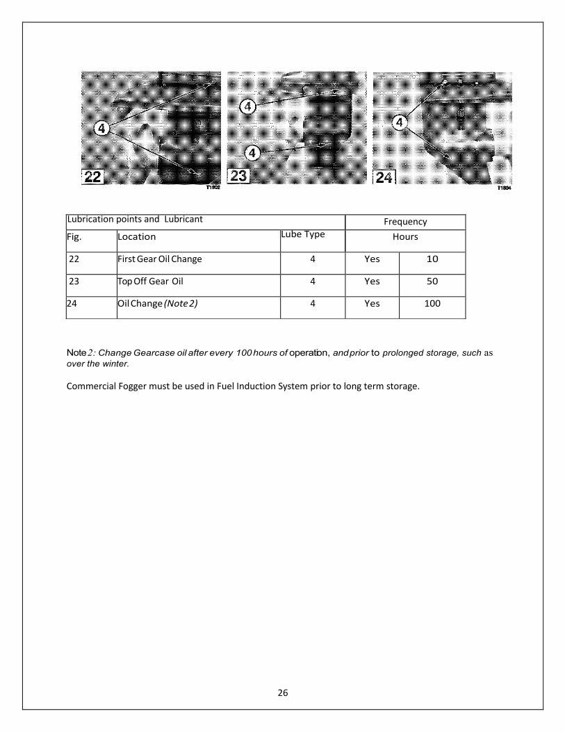
Lubrication points and Lubricant Frequency
Fig. Location Lube Type Hours
22 First Gear Oil Change 4 Yes 10
23 Top Off Gear Oil 4 Yes 50
24 Oil Change (Note 2) 4 Yes 100
27
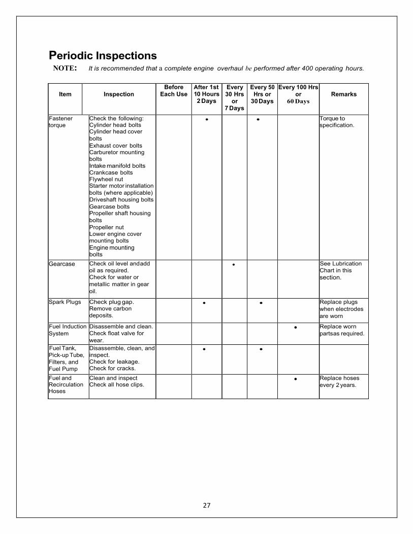
Periodic Inspections NOTE: It is recommended that a complete engine overhaul be performed after 400 operating hours.
Item
Inspection
Before Each Use
After 1st 10 Hours 2 Days
Every 30 Hrs
or 7 Days
Every 50 Hrs or
30 Days
Every 100 Hrs or
60 Days
Remarks
Fastener torque
Check the following: • Cylinder head bolts • Cylinder head cover
bolts
• Exhaust cover bolts • Carburetor mounting
bolts
• Intake manifold bolts
• Crankcase bolts • Flywheel nut • Starter motor installation
bolts (where applicable)
• Driveshaft housing bolts
• Gearcase bolts • Propeller shaft housing
bolts
• Propeller nut • Lower engine cover
mounting bolts
• Engine mounting bolts
• • Torque to specification.
Gearcase • Check oil level and add
oil as required.
• Check for water or
metallic matter in gear
oil.
• See Lubrication
Chart in this
section.
Spark Plugs • Check plug gap. • Remove carbon
deposits.
• • Replace plugs
when electrodes
are worn
Fuel Induction
System
• Disassemble and clean.
• Check float valve for
wear.
• Replace worn
parts as required.
Fuel Tank,
Pick-up Tube,
Filters, and
Fuel Pump
• Disassemble, clean, and
inspect. • Check for leakage. • Check for cracks.
• •
Fuel and Recirculation Hoses
• Clean and inspect • Check all hose clips.
• Replace hoses
every 2 years.
28
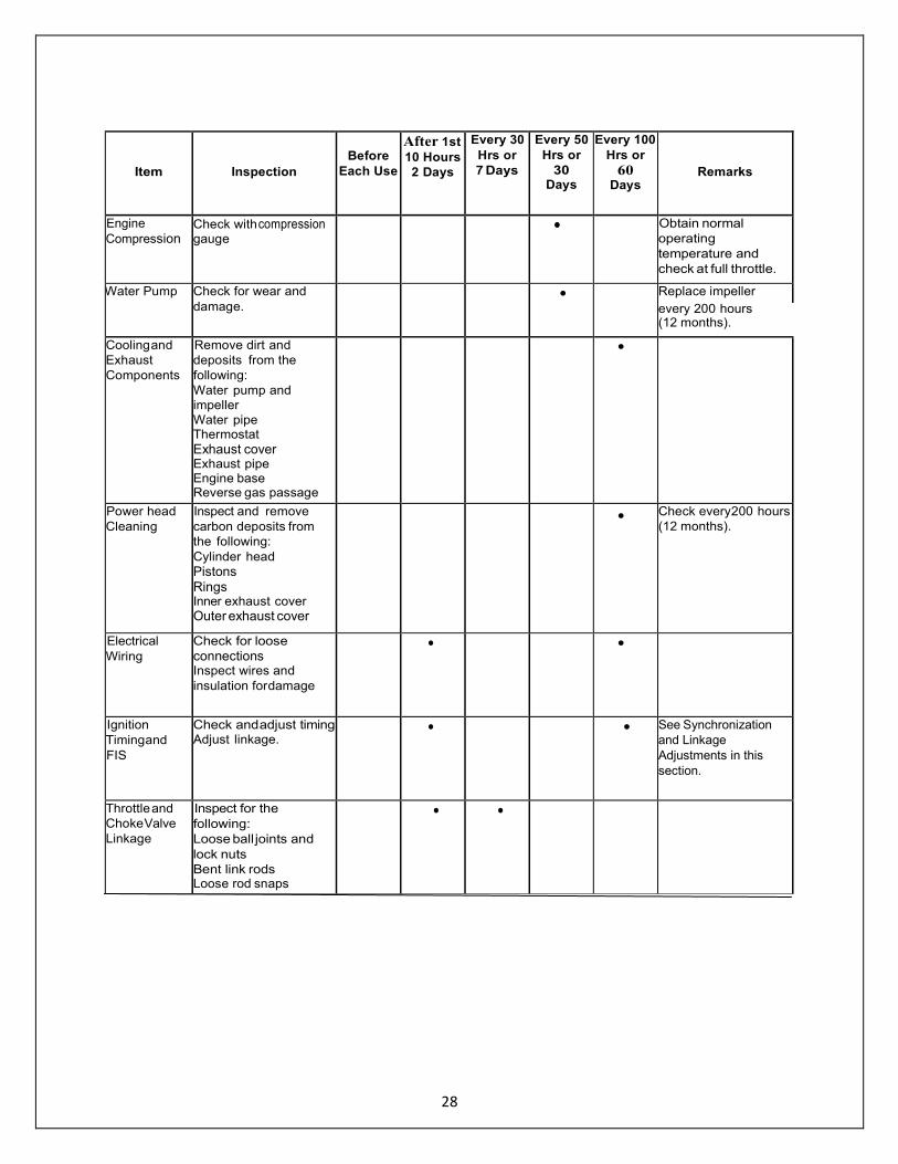
Item
Inspection
Before
Each Use
After 1st
10 Hours
2 Days
Every 30
Hrs or
7 Days
Every 50
Hrs or
30 Days
Every 100
Hrs or
60 Days
Remarks
Engine
Compression • Check with compression
gauge • Obtain normal
operating
temperature and
check at full throttle.
Water Pump • Check for wear and
damage. • Replace impeller
every 200 hours (12 months).
Cooling and
Exhaust
Components
Remove dirt and
deposits from the
following:
• Water pump and
impeller
• Water pipe • Thermostat
• Exhaust cover • Exhaust pipe • Engine base • Reverse gas passage
•
Power head
Cleaning
Inspect and remove
carbon deposits from
the following:
• Cylinder head
• Pistons • Rings • Inner exhaust cover
• Outer exhaust cover
• Check every 200 hours
(12 months).
Electrical
Wiring
• Check for loose
connections • Inspect wires and
insulation for damage
• •
Ignition
Timing and
FIS
• Check and adjust timing • Adjust linkage.
• • See Synchronization
and Linkage
Adjustments in this
section.
Throttle and
Choke Valve
Linkage
Inspect for the
following:
• Loose ball joints and
lock nuts
• Bent link rods • Loose rod snaps
• •
29
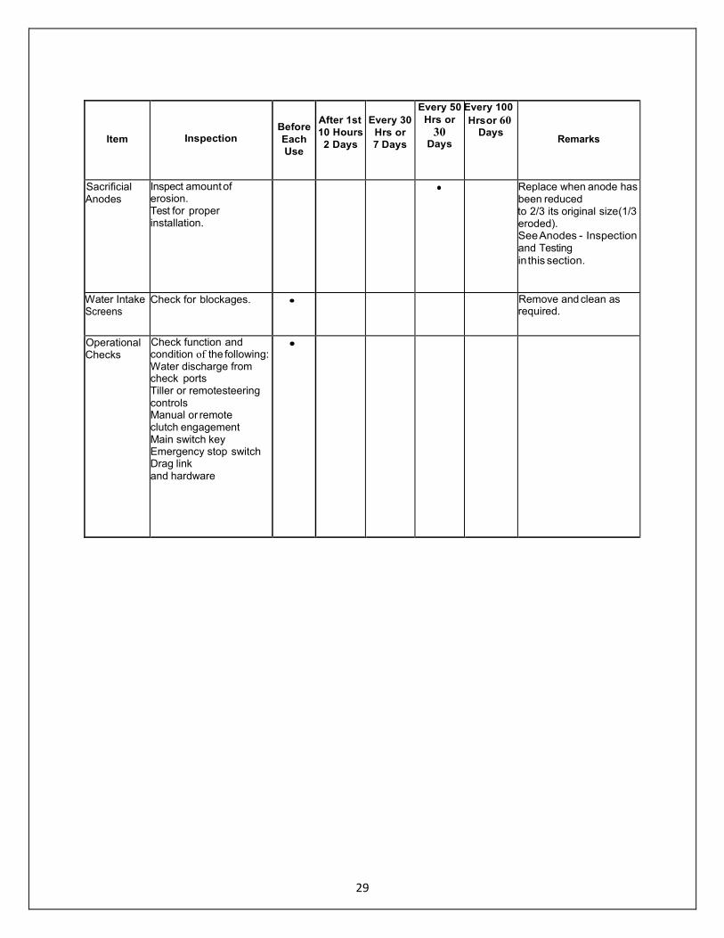
Item
Inspection
Before
Each
Use
After 1st
10 Hours
2 Days
Every 30
Hrs or
7 Days
Every 50
Hrs or
30 Days
Every 100
Hrs or 60 Days
Remarks
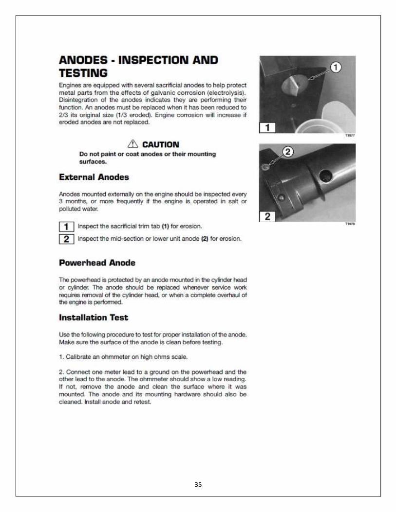
Sacrificial Anodes
• Inspect amount of erosion.
• Test for proper installation.
• Replace when anode has been reduced to 2/3 its original size (1/3 eroded). See Anodes - Inspection and Testing
in this section.
Water Intake Screens
• Check for blockages. • Remove and clean as required.
Operational Checks
Check function and condition of the following:
• Water discharge from check ports
• Tiller or remote steering controls
• Manual or remote clutch engagement
• Main switch key • Emergency stop switch • Drag link
and hardware
•
30
Break In Procedure – Raider 40
Failure to follow the Break-In Procedure I Owner’s Manual and special fuel mixture requirements for break-in may lead to serious engine damage and shortened engine life.
After break-in has been successfully completed fuel bladder should be filled with a 50:1 ration gas/oil premix. If heavy fuels are to be used follow instructions on label.
First 10 Minutes O - 0.16 Hours)
1. Fill the fuel tank with a 25:1 gasoline to oil premix – full synthetic only for Raider 40.
2. Operate the engine at minimum idle speed ONLY. 3. Verify a steady stream of water from the cooling water check port and idle port on the engine,
indicating the water pump is functioning property.
Next 50 Minutes 0.16 to 1Hour) 1. DO NOT operate the engine above 1/2 throttle.
2. DO NOT maintain a constant throttle setting. Vary engine speed from 1/4 to 1/2 throttle every 15 minutes.
NOTE Zodiac boats which come onto plane easily, use full throttle to quickly accelerate onto plane; then immediately reduce throttle t0 1/2 and maintain this speed. Wing Inflatable’s – with Raider should not be any different.
Next Hour (1 to 2 Hours) 1. Use full throttle to quickly accelerate boat onto plane; then immediately reduce throttle to
3/4 and maintain this speed.
2. At intervals, run engine at ¾ throttle for 1-10 minutes then return to ½ throttle for a cooling period.
3. Vary engine speed every 15 minutes. 4. Check for water discharge from cooling water check ports.
Next Eight Hours (2 to 1 0 Hours) 1. Run engine at 3/4 throttle. 2. For short periods of time, run engine at full throttle and then reduce speed back to 3/4
throttle. As this part of the break-in period progresses, open to full throttle for longer and longer periods of time, but never longer than 5 minutes.
3. Vary engine speed every 15 minutes. DO NOT exceed the Full Throttle RPM Range of the engine. See Engine Specifications in this section.
After Break-in Re-torque cylinder head bolts to specification after engine has been run and cylinder head has cooled to the touch.
Empty fuel tank and replenish with a 50:1 gasoline/oil mixture.
31
Tune Up Procedures
Deteriorated or damaged par ts identified during engine tune-up must be replaced in order to maintain safe engine operation.
1. Inspect engine for leaks, missing, loose or damaged parts, or other visible defects.
2. Remove each spark plug and check for fouling, cracks in ceramic, and incorrect gap.
Replace plugs if needed.
3. Check engine compression. Refer to Cylinder Compression -Test in Section 4.
4. Check all wiring, connectors, and clamps for damage. Replace parts as needed.
5. Replace fuel filter and inspect carburetor. Check fuel hoses for deterioration. Replace as
needed.
6. Check for proper clutch engagement and make shift linkage adjustments as needed for proper
operation of the reverse lock mechanism.
Adjust the engine ignition timing and Fuel Induction System. See Synchronization and Linkage Adjustments, this section.
Remove propeller and inspect propeller shaft oil seal for leakage. Inspect propeller thrust washer, and other propeller shaft hardware for damage. Replace as needed.
1. Drain and refill the Gearcase with gear oil. See Engine Specifications in this section.
2. Lubricate all engine components as specified in the Lubrication Chart, this section.
3. Verify that all bolts and screws are torque to specification by applying a torque wrench to each.
4. Run engine in test tank with proper test propeller and check for the following:
Abnormal engine noise.
Improper clutch operation.
Little or no cooling water discharge from check port and idle port.
Fuel leaks from mating surfaces of crankcase.
Fuel leaks from mounting surface of intake manifold.
Cooling water leaks from mating surfaces of cylinder head.
Cooling water leaks from engine mounting surfaces.
Cooling water leaks from exhaust cover mounting surfaces.
Improper idle RPM and stability.
Defective stop switch.
Model Adjustment Part
Raider 40 Shift lever stopper holder : Position onto Shift
lever stopper plate
32
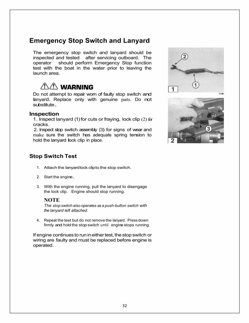
Emergency Stop Switch and Lanyard
The emergency stop switch and lanyard should be inspected and tested after servicing outboard. The operator should perform Emergency Stop function test with the boat in the water prior to leaving the launch area.
Do not attempt to repair worn of faulty stop switch and
lanyard. Replace only with genuine parts. Do not
substitute.
Inspection 1. Inspect lanyard (1) for cuts or fraying, lock clip (2) for
cracks. 2. Inspect stop switch assembly 3) for signs of wear and make sure the switch has adequate spring tension to
hold the lanyard lock clip in place.
Stop Switch Test
1. Attach the lanyard lock clip to the stop switch.
2. Start the engine.
3. With the engine running, pull the lanyard to disengage
the lock clip. Engine should stop running.
NOTE The stop switch also operates as a push-button switch with
the lanyard left attached.
4. Repeat the test but do not remove the lanyard. Press down
firmly and hold the stop switch until engine stops running.
If engine continues to run in either test, the stop switch or wiring are faulty and must be replaced before engine is operated.
33
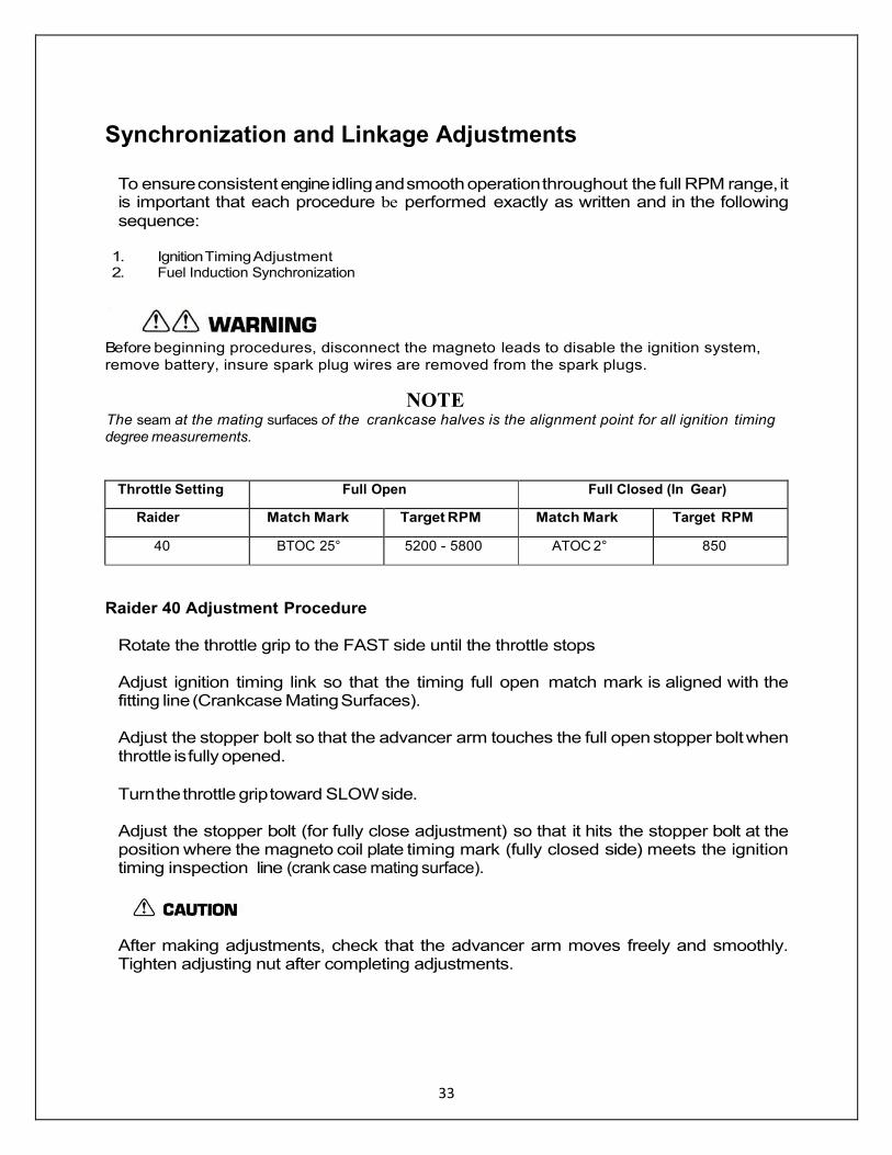
Synchronization and Linkage Adjustments
To ensure consistent engine idling and smooth operation throughout the full RPM range, it is important that each procedure be performed exactly as written and in the following
sequence:
1. Ignition Timing Adjustment 2. Fuel Induction Synchronization
Before beginning procedures, disconnect the magneto leads to disable the ignition system,
remove battery, insure spark plug wires are removed from the spark plugs.
NOTE The seam at the mating surfaces of the crankcase halves is the alignment point for all ignition timing degree measurements.
Throttle Setting Full Open Full Closed (In Gear)
Raider Match Mark Target RPM Match Mark Target RPM
40 BTOC 25° 5200 - 5800 ATOC 2° 850
Raider 40 Adjustment Procedure
Rotate the throttle grip to the FAST side until the throttle stops Adjust ignition timing link so that the timing full open match mark is aligned with the fitting line (Crankcase Mating Surfaces). Adjust the stopper bolt so that the advancer arm touches the full open stopper bolt when throttle is fully opened.
Turn the throttle grip toward SLOW side. Adjust the stopper bolt (for fully close adjustment) so that it hits the stopper bolt at the position where the magneto coil plate timing mark (fully closed side) meets the ignition timing inspection line (crank case mating surface).
After making adjustments, check that the advancer arm moves freely and smoothly. Tighten adjusting nut after completing adjustments.
T1972
2
3
34
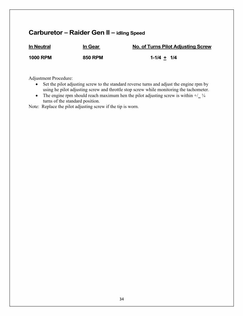
Carburetor – Raider Gen II – idling Speed
In Neutral In Gear No. of Turns Pilot Adjusting Screw 1000 RPM 850 RPM 1-1/4 + 1/4
Adjustment Procedure:
Set the pilot adjusting screw to the standard reverse turns and adjust the engine rpm by
using he pilot adjusting screw and throttle stop screw while monitoring the tachometer.
The engine rpm should reach maximum hen the pilot adjusting screw is within +/_ ¼
turns of the standard position.
Note: Replace the pilot adjusting screw if the tip is worn.
35
36
SECTION 3 - FUEL SYSTEM
General Precautions
Gasoline is extremely flammable and can explode if mishandled. JP-5/8 is also hazardous.
1. Before performing any service work on the fuel system, read and understand Section 1 - Service
Safety.
2. Before servicing the fuel system, disable the ignition system by removing all spark plug leads to
prevent accidental starting of engine.
3. Fuel leakage can contribute to a fire or explosion. After service work is complete and engine is
fully assembled, always run the engine momentarily to pressurize the fuel system. Then
check for leaks.
4. Never attempt to run the engine with any fuel system component removed or disconnected.
5. Check fuel hoses and other non-metallic component’s for indications of damage or
deterioration. Always replace components wi th authorized factory replacement parts suitable
for fuel systems.
6. Clean up fuel spills immediately and store rags in approved containers. Keep drained fuel in approved
containers for proper disposal.
7. When using compressed air to clean or dry parts, make sure the air supply is regulated not to
exceed 25 psi [172 kPa / 1.76 kg/cm2].
Service Specifications,
NOTE Refer to Section 2 for Standard Torque Values chart.
Description 40 Torque
Fuel Induction Mounting Bolt 40 - 55
4.6 - 6.2 0.47 - 0.64
Air Silencer Cover BoIt/Screw•
43.2 - 54.6
4.9 - 6.4 0.50 - 0.65
Inlet Manifold Mounting Bolts 43.2 - 54.6
4.9 - 6.4
0.50 - 0.65
•Loctite #242 required
No Manufacturer Special Tools are required.

37
General Equipment Required
Fuel Pressure Gauge, 0 - 15 psi [0 - 1 kg/cm•] Tee Fitting with 3/8 in O.D. barbs [9.5 mm O . D .] Torque Wrench, 0 - 150 in-lb [0- 17 N·m/0 - 1.7kg-m] Digital Pulse Tachometer Flexible Fuel Tubing, 3/8 in I.D. x 5 in. [9.5 mm I.D. x 127 mm]
Consumable Supplies Required Thread Locking Compound, Loctite 272
Isopropyl Alcohol Cleaning Solvent Lint-free Wipes
Fuel System Requirements Acceptable Fuel - Gasoline
Any gasoline with pump posted octane rating over 87 (research octane rating of 91) and with no more that 10% Ethanol by volume.
Acceptable Fuel – Heavy Fuels JP-5/8; kerosene; Jet-A, diesel #2; are acceptable. It is critical to insert additive in 50:1 mix. 50:1 mix must be used in addition to the additive.
Unacceptable Fuel Gasoline with more than 5% Methanol (even if it contains co-solvents or corrosion inhibitor) or more than 10% Ethanol, regardless of the octane rating.
Fuel Storage Life Fuel stored more than three months should not be used.
Acceptable Lubricant Any NMMA certified TC-W3 2-cycle outboard engine oil is acceptable for fuel tank premix applications on gasoline. Do not use automotive oils which can damage the engine and shorten spark plug life. For Heavy Fuels (JP-5/8, Jet-A, kerosene, diesel) use additive (Mercury JP or Raider JP with additive).
Mix Ratios
A 25 : 1 gasoline/oil mixture is required during engine break in. Refer to Break-In Procedure in Section 2.
Gasoline Premixing A 50:1 gasoline/oil mixture (2% oil) is required. New engines or reconditioned power heads require a 25:1 gasoline/oil mixture 4% oil) during break-in. Heavy Fuel Premixing A 50:1 Heavy Fuel Additive is required. Each container will support a 6 gallon bladder.

38
Fuel System
39
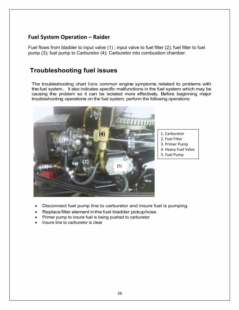
Fuel System Operation – Raider
Fuel flows from bladder to input valve (1) ; input valve to fuel filter (2); fuel filter to fuel pump (3); fuel pump to Carburetor (4); Carburetor into combustion chamber.
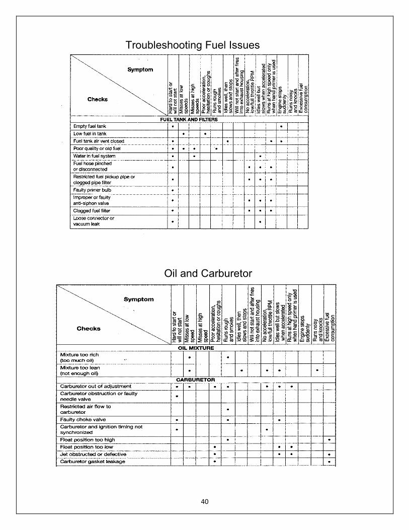
Troubleshooting fuel issues
The troubleshooting chart lists common engine symptoms related to problems with the fuel system. It also indicates specific malfunctions in the fuel system which may be causing the problem so it can be isolated more effectively. Before beginning major troubleshooting operations on the fuel system, perform the following operations:
Disconnect fuel pump line to carburetor and insure fuel is pumping.
Replace filter element in the fuel bladder pickup hose.
Primer pump to insure fuel is being pushed to carburetor
Insure line to carburetor is clear
(1)
(2) (3)
(4)
(5)
1. Carburetor 2. Fuel Filter 3. Primer Pump 4. Heavy Fuel Valve 5. Fuel Pump
40
Oil and Carburetor
Troubleshooting Fuel Issues
41
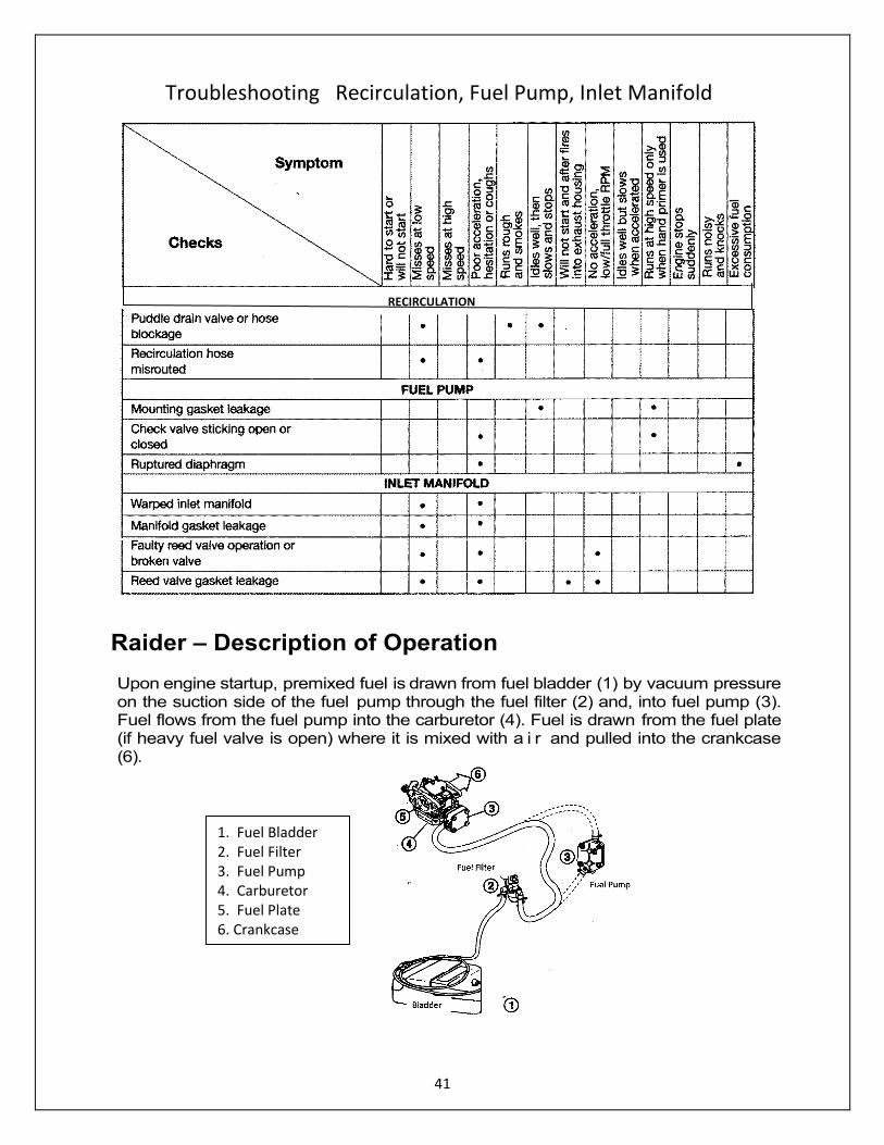
Raider – Description of Operation Upon engine startup, premixed fuel is drawn from fuel bladder (1) by vacuum pressure on the suction side of the fuel pump through the fuel filter (2) and, into fuel pump (3). Fuel flows from the fuel pump into the carburetor (4). Fuel is drawn from the fuel plate (if heavy fuel valve is open) where it is mixed with a i r and pulled into the crankcase (6).
RECIRCULATION
Troubleshooting Recirculation, Fuel Pump, Inlet Manifold
1. Fuel Bladder 2. Fuel Filter 3. Fuel Pump 4. Carburetor 5. Fuel Plate 6. Crankcase
42
Fuel Pump [3] above
The fuel pump is integral with the carburetor and mounted on the side of the crankcase and contains one or more internal diaphragms (1). The diaphragms move in response to changing crankcase pressures (2) which draws fuel in (3) and pumps fuel out (4). A series of check valves (5) in the pump ensure that fuel moves only in one direction.
Carburetor [1] above
The carburetor is used a pilot system and works in conjunction with the fuel plate to deliver an atomized fuel mixture to the engine for combustion under varying operating conditions.
Recirculation
Recirculation hoses at the inlet manifold and crankcase re-circulate unburned fuel for engine consumption.
Fuel Bladder Connection Raider provides a 10 ft. fuel hose from the bladder to the Raider 40. The hose comes with a connector that goes into the fuel bladder to insure proper connection.
Cleaning Water or dirt in the fuel bladder can cause fuel starvation and engine problems. Clean and inspect fuel bladder once a year or after long time storage (more than 3 months).
1. Disconnect fuel line from fuel bladder.
2. Empty remaining fuel from bladder and properly dispose.
3. Fill tank 1/4 with fresh gasoline and install cap. Rigorously shake tank for 30
seconds to loosen dirt particles.
4. Empty gasoline from tank and properly dispose.
5. Inspect tank components before refilling.
Inspection
All worn, damaged, or missing parts must be replaced.

43
Fuel Line Description
1. Clamp P/N 332702010M 2. Clamp P/N 3C7702170M 3. Fuel Connector to Bladder P/N 3B2702810M 4. Fuel Hose - 7MM (5/16") Use fuel line material 5. Fuel Connector Engine side female P/N 3B2702501M 6. Fuel Hose - 7MM (5/16") 7. Complete Assembly – No Part No. available 8. Joint Assembly outer – P/N: 3C7702241M 9. Joint Assembly inner – P/N: 3C7702201M 10. Primer Bulb – P/N 3C7702111M
*MALE QUICK CONNECTOR
The connector to be inserted into Fuel Bladder is attached to the fuel hose. It has a barbed connector to insure a good fit.
Fuel bladder is connected to the engine by a hose with a primer bulb. The primer bulb forces fuel into the Fuel Induction System for engine starting. Check valves on each side of the primer
bulb maintain fuel flow, in one direction only, from the tank to the engine. Disassembly
NOTE Direction of fuel flow as indicated by the arrow on the primer bulb.
1. Remove and discard hose clamps (1) and primer bulb clamps (2) as required. 2. Remove tank connector (3) and hose (4). 3. Remove engine connector (5) and hose (6).
4. Remove primer bulb assembly 7. Remove check valves 5. (8) and (9) from primer bulb (10).
Cleaning and Inspection
1. Clean components using soap and water. 2. Dry all components with low pressure compressed air. Make sure all parts and passages
are completely dry. Inspect primer bulb and hoses for cracks and deterioration. 3. Inspect bladder and engine quick connectors for damage and wear. Make sure
check valves in quick disconnects open freely when pressed. 4. Inspect primer bulb check valves for damage. 5. Reassemble all components.
T1110
5-Bladder connection to Raider See Parts and Assembly Manual R40 ES-001-15-2 for part numbers.

44
Disassembly – Fuel Pump
45
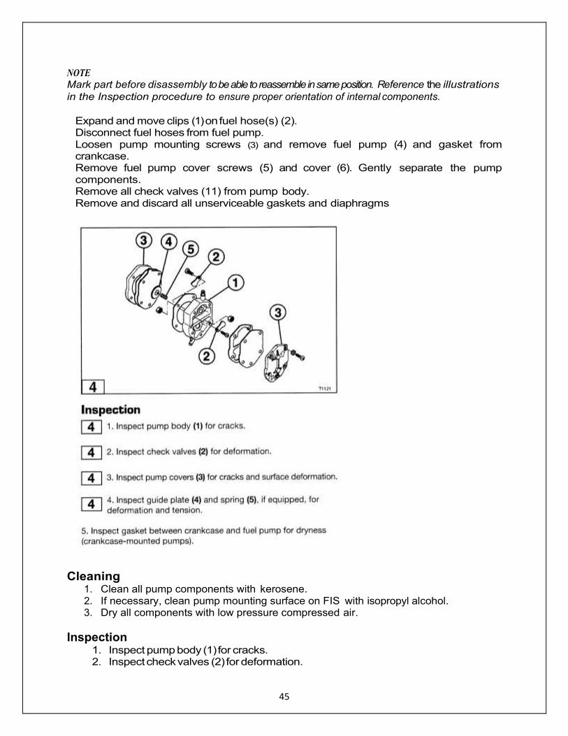
NOTE
Mark part before disassembly to be able to reassemble in same position. Reference the illustrations
in the Inspection procedure to ensure proper orientation of internal components.
Expand and move clips (1) on fuel hose(s) (2). Disconnect fuel hoses from fuel pump. Loosen pump mounting screws (3) and remove fuel pump (4) and gasket from crankcase. Remove fuel pump cover screws (5) and cover (6). Gently separate the pump components. Remove all check valves (11) from pump body. Remove and discard all unserviceable gaskets and diaphragms
Cleaning
1. Clean all pump components with kerosene. 2. If necessary, clean pump mounting surface on FIS with isopropyl alcohol. 3. Dry all components with low pressure compressed air.
Inspection 1. Inspect pump body (1) for cracks. 2. Inspect check valves (2) for deformation.

46
3. Inspect pump covers (3) for cracks and surface deformation. 4. Inspect guide plate (4) and spring (5), if equipped, for deformation and tension. 5. Inspect gasket between crankcase and fuel pump for dryness (crankcase-
mounted pumps).
Assembly 1. Install all check valves in pump body.
2. Fully assemble fuel pump. All unserviceable gaskets and diaphragms must be replaced.
3. Install fuel pump. Use Loctite 242 on mounting screw threads.
4. Connect fuel hoses to fuel pump.
Carburetor
Removal
1. Remove motor cover 2. Disconnect fuel supply. 3. Remove fuel hose from carburetor 4. Loosen clamp bolt s and remove carburetor.
Use the following precautions during carburetor disassembly
1. Clean plastic parts with warm soapy water.
2. Dry all components with low pressure compressed air.
3. DO NOT inspect passages or holes with wire or similar materials. Doing so may
16
47
scratch or enlarge jet holes and alter the fuel-air ratio.
NOTE Before inspection, all fuel induction components must be cleaned. All worn or damaged parts must be replaced.
Removal of Carburetor 1. Remove the air silencer 2. Remove the carburetor primer rod linkage 3. Remove the fuel hose 4. Remove carburetor and fuel plate - discard carburetor base gaskets
5. Remove drain screw from float chamber – allow to drain
6. Remove float chamber 7. Remove float valve assembly, if serviceable, remove needle seat 8. Remove jets, plugs, nozzles from carburetor 9. Remove pilot adjust and throttle stop screw Replace any worn parts and re-assemble.
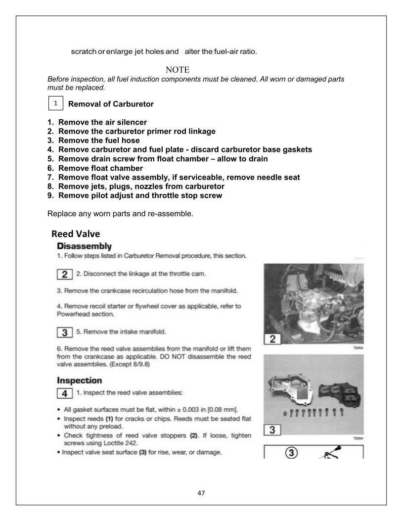
Reed Valve
1
48
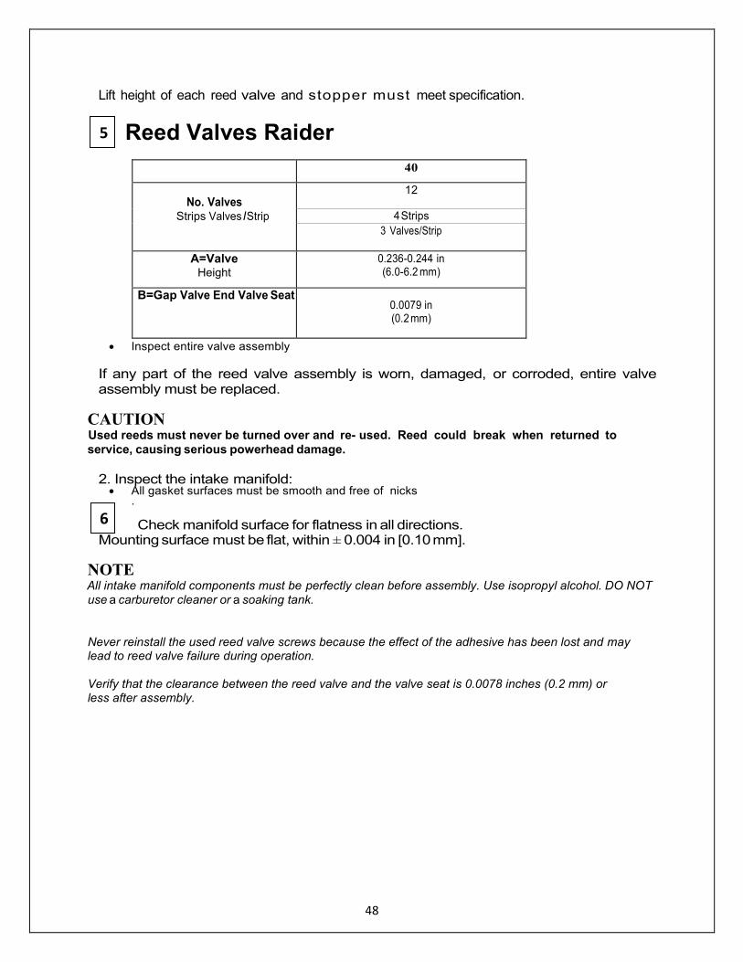
Lift height of each reed valve and stopper must meet specification.
Reed Valves Raider
40
No. Valves Strips Valves I Strip
12
4 Strips
3 Valves/Strip
A=Valve Height
0.236-0.244 in (6.0-6.2 mm)
B=Gap Valve End Valve Seat
0.0079 in (0.2 mm)
Inspect entire valve assembly
If any part of the reed valve assembly is worn, damaged, or corroded, entire valve assembly must be replaced.
CAUTION Used reeds must never be turned over and re used. Reed could break when returned to
service, causing serious powerhead damage.
2. Inspect the intake manifold: All gasket surfaces must be smooth and free of nicks
.
Check manifold surface for flatness in all directions. Mounting surface must be flat, within ± 0.004 in [0.10 mm].
NOTE All intake manifold components must be perfectly clean before assembly. Use isopropyl alcohol. DO NOT use a carburetor cleaner or a soaking tank.
Never reinstall the used reed valve screws because the effect of the adhesive has been lost and may lead to reed valve failure during operation. Verify that the clearance between the reed valve and the valve seat is 0.0078 inches (0.2 mm) or less after assembly.
5
6
49
SECTION 4 - POWERHEAD
General Precautions
Before performing any service work on the powerhead, read and understand the Service Safety section at the beginning of this manual.
Use the manufacturer special tools as indicated during servicing of the powerhead.
Use caution when performing tests with the engine cover removed. Do not wear loose clothing or jewelry. Keep hair, hands, and clothing away from the flywheel.
Check entire fuel system for leaks after servicing the powerhead to prevent fire or explosion.
Make sure all ignition and electrical leads are properly routed and clamped in their original positions.
Disable the ignition system and disconnect the battery when servicing the powerhead.
Replace locking fasteners when their locking feature becomes weak. Use only factory replacement parts.
Always inspect and test the start-in-gear prevention system before returning engine to customer.
50
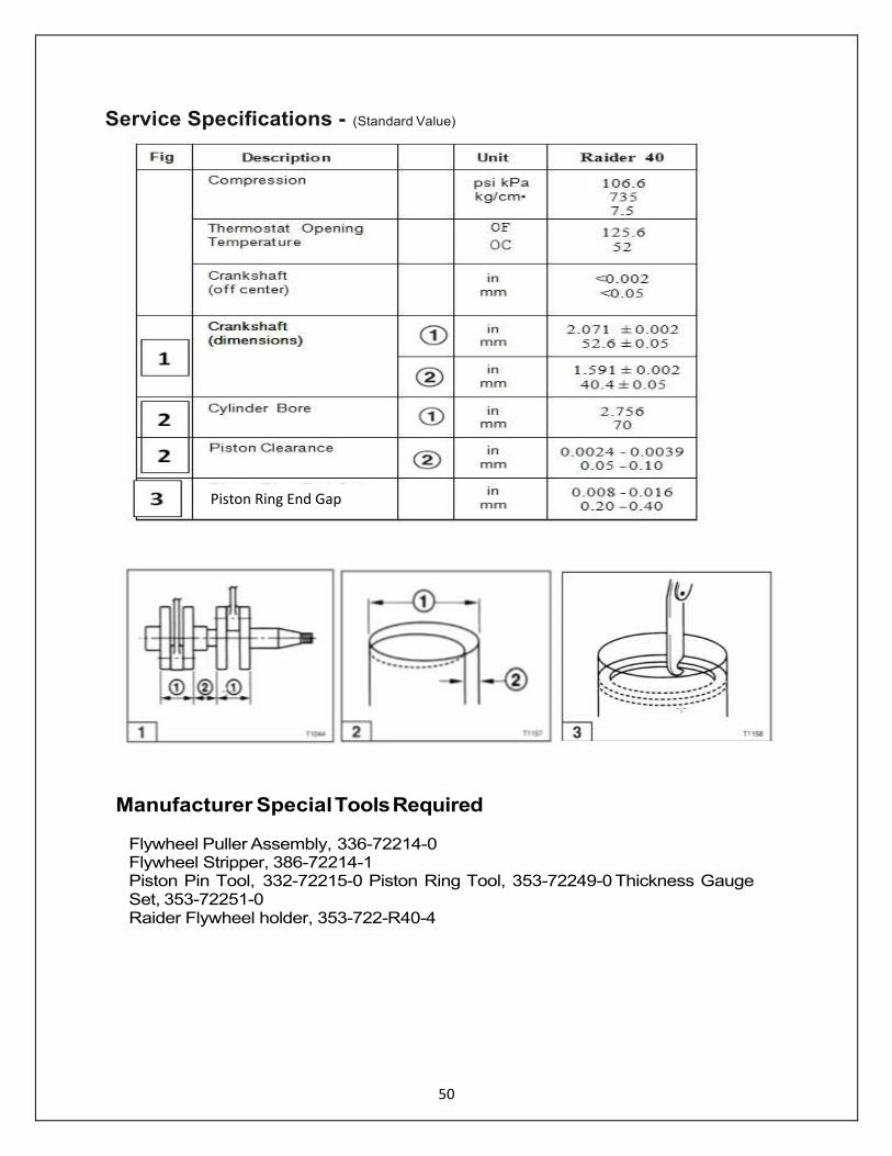
Service Specifications - (Standard Value)
Manufacturer Special Tools Required Flywheel Puller Assembly, 336-72214-0 Flywheel Stripper, 386-72214-1 Piston Pin Tool, 332-72215-0 Piston Ring Tool, 353-72249-0 Thickness Gauge Set, 353-72251-0 Raider Flywheel holder, 353-722-R40-4
Piston Ring End Gap
51
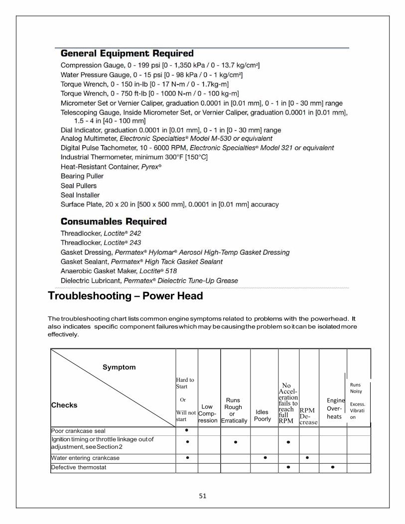
Troubleshooting – Power Head
The troubleshooting chart lists common engine symptoms related to problems with the powerhead. It
also indicates specific component failures which may be causing the problem so it can be isolated more
effectively.
Symptom
Checks
Hard to Start
Or
Will not start
Low Comp-ression
Runs Rough or Erratically
Idles Poorly
No Accel- eration fails to reach full RPM
RPM De-creases
Poor crankcase seal • Ignition timing or throttle linkage out of
adjustment, see Section 2 • • •
Water entering crankcase • • • Defective thermostat • •
Engine Over-heats
Runs Noisy Excess. Vibration

52
Fouled, defective or incorrect spark plug;
wrong gap setting • • • • •
Worn or defective cylinder, piston, rings or
warped head • • • • Blown cylinder head or engine base gasket • • • • • • • Worn connecting rod or crankshaft bearings,
internal wear limits out of specification • • •
Defective ignition components, see Section 7 • • •
Carbon accumulation in combustion chamber • • •
.
The Raider outboards are unusual from commercial outboards; the head of the Raider has included two dewatering valves that allow water to escape after submersion – when opened. The heads have also been modified to allow more water flow which keeps the engine cooler and will increase reliability and life of the Raider.
53
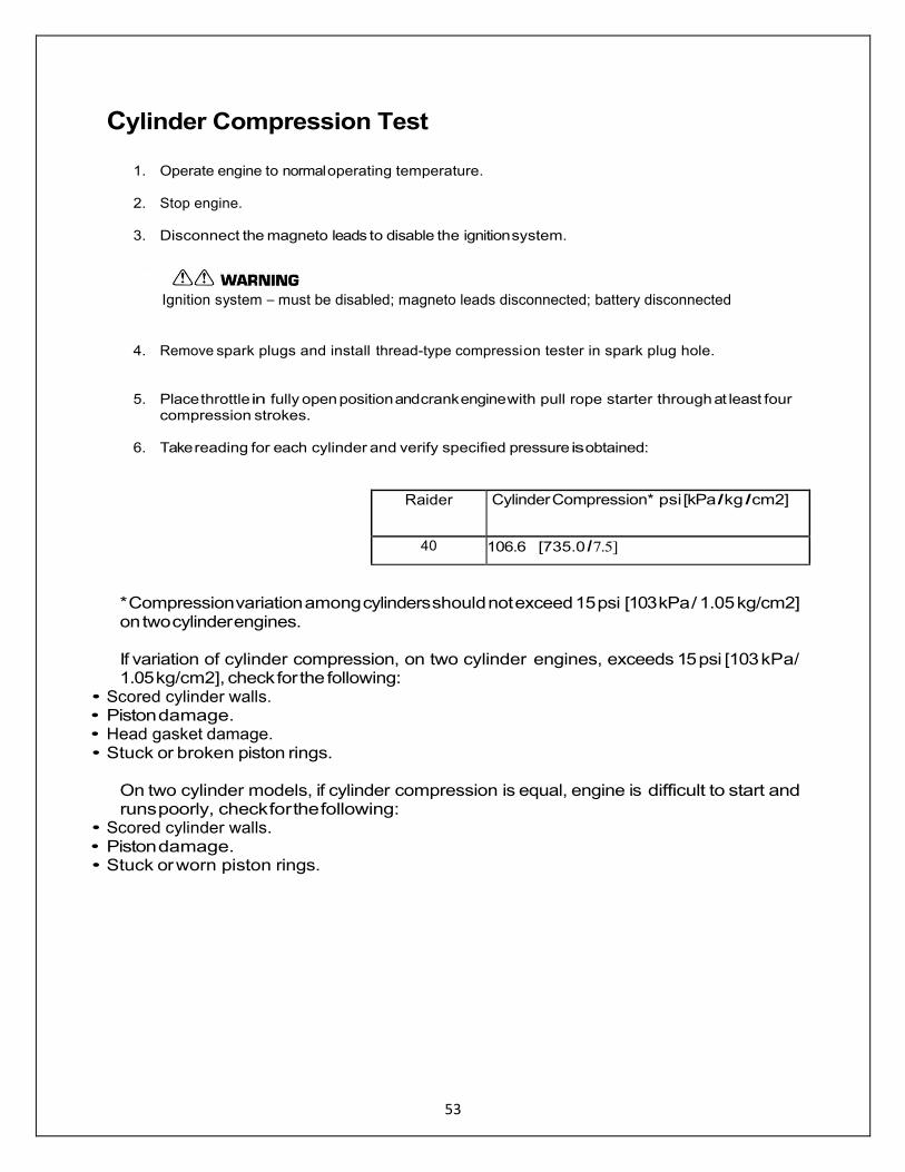
Cylinder Compression Test
1. Operate engine to normal operating temperature.
2. Stop engine.
3. Disconnect the magneto leads to disable the ignition system.
Ignition system – must be disabled; magneto leads disconnected; battery disconnected
4. Remove spark plugs and install thread-type compression tester in spark plug hole.
5. Place throttle in fully open position and crank engine with pull rope starter through at least four
compression strokes.
6. Take reading for each cylinder and verify specified pressure is obtained:
Raider Cylinder Compression* psi [kPa I kg I cm2]
40 106.6 [735.0 I 7.5]
* Compression variation among cylinders should not exceed 15 psi [103 kPa / 1.05 kg/cm2] on two cylinder engines.
If variation of cylinder compression, on two cylinder engines, exceeds 15 psi [103 kPa/ 1.05 kg/cm2], check for the following:
• Scored cylinder walls. • Piston damage. • Head gasket damage. • Stuck or broken piston rings.
On two cylinder models, if cylinder compression is equal, engine is difficult to start and runs poorly, check for the following:
• Scored cylinder walls. • Piston damage. • Stuck or worn piston rings.
54
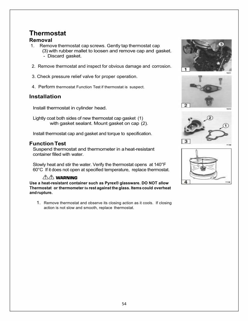
Thermostat Removal 1. Remove thermostat cap screws. Gently tap thermostat cap
(3) with rubber mallet to loosen and remove cap and gasket. - Discard gasket.
2. Remove thermostat and inspect for obvious damage and corrosion. 3. Check pressure relief valve for proper operation. 4. Perform thermostat Function Test if thermostat is suspect.
Installation
Install thermostat in cylinder head. Lightly coat both sides of new thermostat cap gasket (1) with gasket sealant. Mount gasket on cap (2). Install thermostat cap and gasket and torque to specification.
Function Test Suspend thermostat and thermometer in a heat-resistant container filled with water. Slowly heat and stir the water. Verify the thermostat opens at 140°F 60°C If it does not open at specified temperature, replace thermostat.
Use a heat-resistant container such as Pyrex® glassware. DO NOT allow
Thermostat or thermometer to rest against the glass. Items could overheat and rupture.
1. Remove thermostat and observe its closing action as it cools. If closing
action is not slow and smooth, replace thermostat.

55
RPM Performance Test
Do not perform RPM test if engine shows signs of overheating. Perform this test with correct test propeller Installed and with the engine in a test tank.
1. Operate engine up to normal operating temperature. 2. Stop engine and install tachometer. 3. Start and run engine at NEUTRAL idle and verify specified RPM is obtained. 4. If test tank conditions permit, run engine in forward gear at trolling and full throttle speeds and
check for correct RPM:
Raider 40
NEUTRAL RPM
Trolling Speed RPM
Ful Throttle Speed RPM
40 950 850 5200 - 5800
If test results vary, refer to Troubleshooting in this section.
56
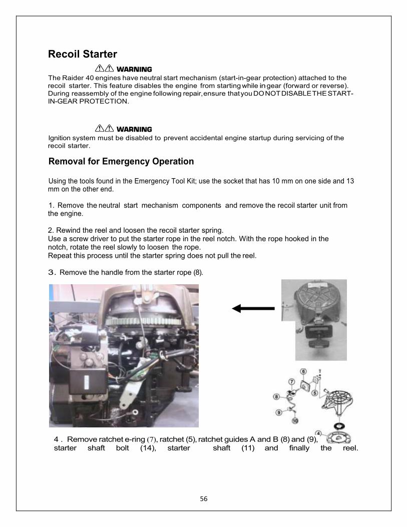
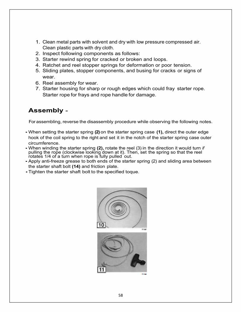
Recoil Starter
The Raider 40 engines have neutral start mechanism (start-in-gear protection) attached to the
recoil starter. This feature disables the engine from starting while in gear (forward or reverse). During reassembly of the engine following repair, ensure that you DO NOT DISABLE THE START-
IN-GEAR PROTECTION.
Ignition system must be disabled to prevent accidental engine startup during servicing of the recoil starter.
Removal for Emergency Operation Using the tools found in the Emergency Tool Kit; use the socket that has 10 mm on one side and 13 mm on the other end. 1. Remove the neutral start mechanism components and remove the recoil starter unit from the engine. 2. Rewind the reel and loosen the recoil starter spring. Use a screw driver to put the starter rope in the reel notch. With the rope hooked in the notch, rotate the reel slowly to loosen the rope. Repeat this process until the starter spring does not pull the reel. 3. Remove the handle from the starter rope (8).
4 . Remove ratchet e-ring (7), ratchet (5), ratchet guides A and B (8) and (9),
starter shaft bolt (14), starter shaft (11) and finally the reel.
57
Cleaning and Inspection All worn, damaged, or missing parts must be replaced.
58
1. Clean metal parts with solvent and dry with low pressure compressed air.
Clean plastic parts with dry cloth.
2. Inspect following components as follows:
3. Starter rewind spring for cracked or broken and loops.
4. Ratchet and reel stopper springs for deformation or poor tension. 5. Sliding plates, stopper components, and busing for cracks or signs of
wear.
6. Reel assembly for wear. 7. Starter housing for sharp or rough edges which could fray starter rope.
Starter rope for frays and rope handle for damage.
Assembly - For assembling, reverse the disassembly procedure while observing the following notes.
• When setting the starter spring (2) on the starter spring case (1), direct the outer edge
hook of the coil spring to the right and set it in the notch of the starter spring case outer
circumference. • When winding the starter spring (2), rotate the reel (3) in the direction it would turn if
pulling the rope (clockwise looking down at it). Then, set the spring so that the reel rotates 1/4 of a turn when rope is fully pulled out.
• Apply anti-freeze grease to both ends of the starter spring (2) and sliding area between
the starter shaft bolt (14) and friction plate.
• Tighten the starter shaft bolt to the specified toque.
59
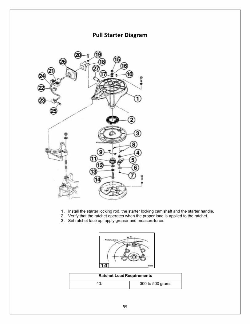
1. Install the starter locking rod, the starter locking cam shaft and the starter handle. 2. Verify that the ratchet operates when the proper load is applied to the ratchet. 3. Set ratchet face up, apply grease and measure force.
Ratchet Load Requirements
40: 300 to 500 grams
Pull Starter Diagram

60
Flywheel NOTE Flywheel magneto must be of a particular strength in order to run the ignition system. Flywheels seldom
go bad and would only be replaced as a last resort in solving an ignition problem.
Flywheel is under high torque and requires the use of special tools for removal and installation. Failure to use the specified tools can result in injury or damage to the flywheel or coil plate
electrical components.
The force needed to loosen and tighten the flywheel nut requires flywheel be removed
and installed with engine mounted and secured on an engine stand.
NOTE Reference the following specification table for flywheel Removal and Installation special tool requirements. Wheel Puller Part Number: 211-0 (336-72214-1) for Raider 40 Outboard
Ignition System must be disabled to prevent accidental engine startup during removal of the flywheel.
1. Remove recoil starter and starter pulley
2. Determine the direction of rotation for removing flywheel nut by running your thumbnail along the
threads of the crankshaft.
Inspection 1. Inspect flywheel for cracks, chips, and damaged taper.
2. Inspect crankshaft for thread damage and damaged taper.
3. Inspect flywheel key and keyway for damage.

61
Installation of Flywheel
Ignition system must be disabled to prevent accidental engine startup during installation of
the flywheel.
1. Remove all grease from tapered portion of flywheel and crankshaft with solvent.
2. Check flywheel key is inserted in crankshaft.
3. Align flywheel keyway and install on crankshaft.
4. Install the flywheel washer. Install puller arm (1) on flywheel using bolts (2).
5. Hold puller arm and torque flywheel nut to specification.
6. Install recoil starter.
Model Flywheel Torque
Raider 40
1043 - 1217 in-lb
118 - 137 N-m
12 - 14 kg-m
62
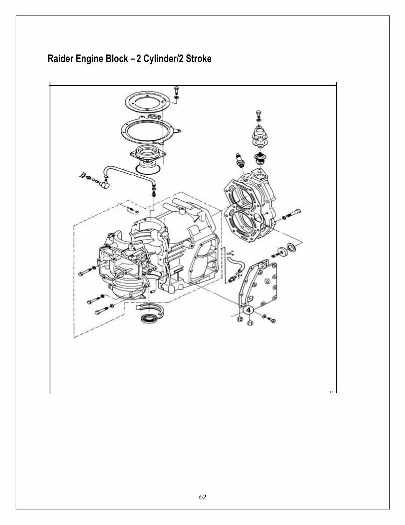
Raider Engine Block – 2 Cylinder/2 Stroke
r1 I
\
------
,
I • I
I I I I
: .1
I ..._ _ _ _ _t._ _JI
ill I
TIB77
63
Removal of Raider Engine
Ignition system must be disabled – disconnect magneto leads and disconnect battery
NOTE If service work requires flywheel to be removed, remove flywheel before lifting powerhead from the rest of
the engine. See Flywheel, this section.
NOTE Mark the mounting location of all clamps so they can be returned to their original positions during assembly of the powerhead.
1. Disconnect the battery and fuel tank. 2. Disable the ignition system and disconnect the battery terminals on the power
head. 3. Disconnect all electrical connections 4. Disconnect fuel INPUT hose from fuel filter. 5. Disconnect pilot water hose from exhaust cover.
Complete the following operations.
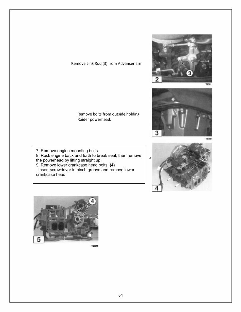
Remove link rod (3) from advancer arm
Disconnect shift cable from shift arm.
Disconnect throttle cable from advancer arm.
Remove engine mounting bolts. Rock engine back and forth to break seal, then remove the
powerhead by lifting straight up.
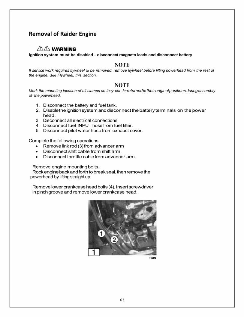
Remove lower crankcase head bolts (4). Insert screwdriver in pinch groove and remove lower crankcase head.
64
f
Remove Link Rod (3) from Advancer arm
Remove bolts from outside holding Raider powerhead.
7. Remove engine mounting bolts. 8. Rock engine back and forth to break seal, then remove the powerhead by lifting straight up. 9. Remove lower crankcase head bolts (4) . Insert screwdriver in pinch groove and remove lower crankcase head.
65
Disassembly – Power Head
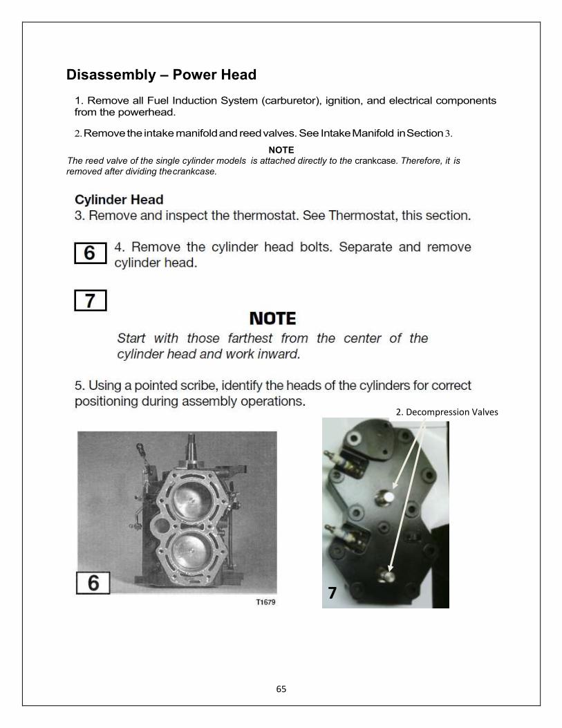
1. Remove all Fuel Induction System (carburetor), ignition, and electrical components from the powerhead.
2. Remove the intake manifold and reed valves. See Intake Manifold in Section 3.
NOTE The reed valve of the single cylinder models is attached directly to the crankcase. Therefore, it is removed after dividing the crankcase.
2. Decompression Valves
7
66
Inside view of Raider 40 Powerhead 1. Look for any damage 2. Replace gasket 3. Use Permatex Aviation gasket
cement when assembly
67
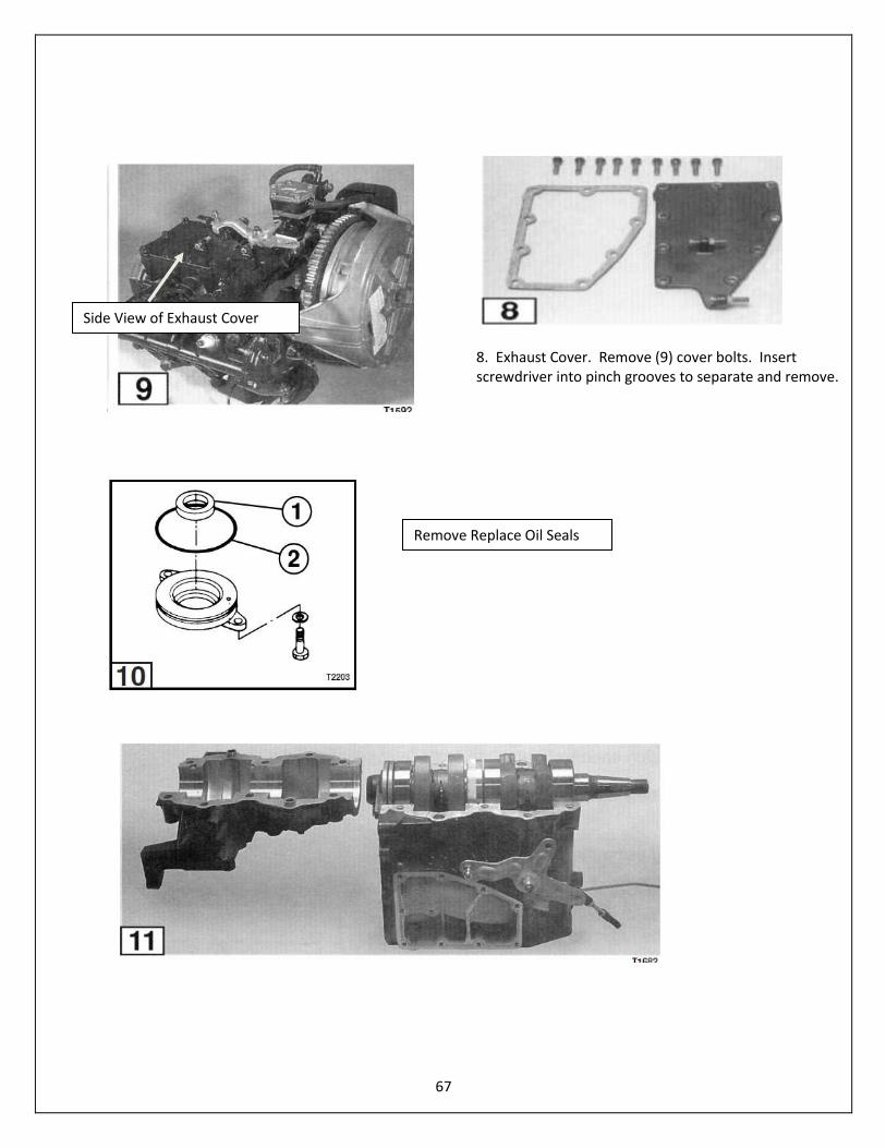
8. Exhaust Cover. Remove (9) cover bolts. Insert screwdriver into pinch grooves to separate and remove.
Side View of Exhaust Cover
Remove Replace Oil Seals

68
Pistons
NOTE Pistons, rings, and connecting rod bearings are wear parts which seat with operation of the
engine. Make sure these parts are marked and kept together so they can be returned to
their original positions during assembly.
15. Remove piston pin clip (6) from each side of each piston. (Discard the clips).
69
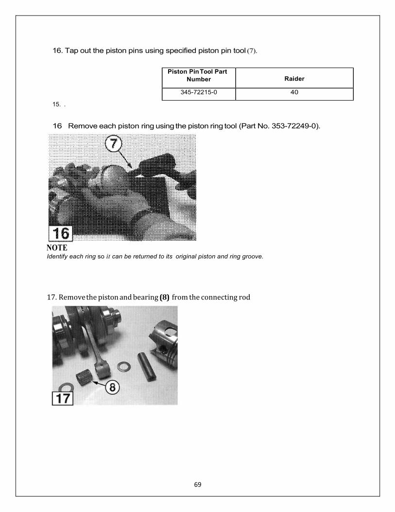
16. Tap out the piston pins using specified piston pin tool (7).
Piston Pin Tool Part
Number
Raider
345-72215-0 40
15. .
16 Remove each piston ring using the piston ring tool (Part No. 353-72249-0).
NOTE Identify each ring so it can be returned to its original piston and ring groove.
17. Remove the piston and bearing (8) from the connecting rod

70

71
72
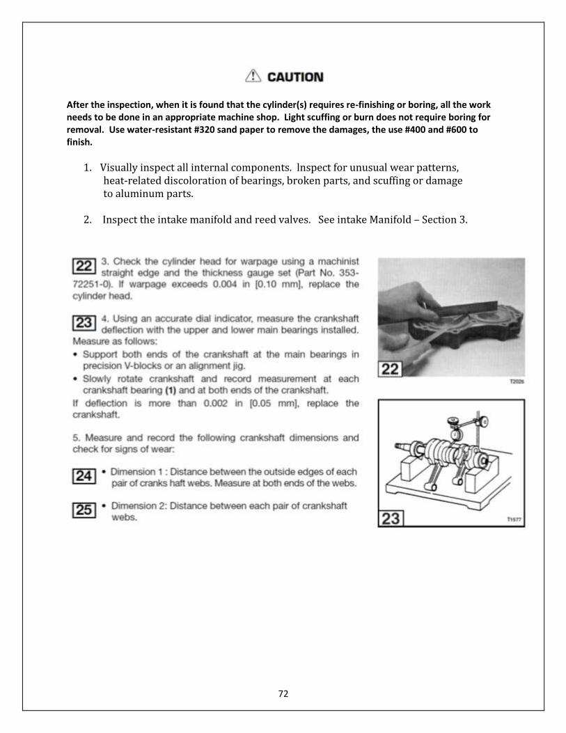
After the inspection, when it is found that the cylinder(s) requires re-finishing or boring, all the work needs to be done in an appropriate machine shop. Light scuffing or burn does not require boring for removal. Use water-resistant #320 sand paper to remove the damages, the use #400 and #600 to finish.
1. Visually inspect all internal components. lnspect for unusual wear patterns, heat-related discoloration of bearings, broken parts, and scuffing or damage to aluminum parts.
2. Inspect the intake manifold and reed valves. See intake Manifold – Section 3.

73

74
75
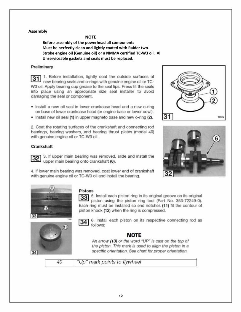
Assembly NOTE Before assembly of the powerhead all components Must be perfectly clean and lightly coated with Raider two- Stroke engine oil (Genuine oil) or a NMMA certified TC-W3 oil. All Unserviceable gaskets and seals must be replaced.
76
Raider 40 is a two-cylinder; the second piston is identical to piston one.
77
11. Head gasket requires adhesive. Recommended is Permatex Aviation cement. Install head gasket to Raider 40 outboard. Gasket is required between head and dewatering cover plate. Permatex Aviation cement is recommended. This gasket material does not harden like typical cement; excellent for submersion characteristics.
12. Install cylinder head. Torque bolts to specifications.
NOTE
Start with bolts closest to the center of the crankcase and work outward.
38 Head Assembly with dewatering lever
78
40 Thermostat located outside dewatering plate.
79

80
81
SECTION 5 – MIDSECTION
General Precautions Before performing any service work on the midsection, read and understand the Service Safety section at
the beginning of this manual.
Replace locking fasteners when their locking feature becomes weak. Use only factory replacement parts.
When using compressed air to clean or dry parts, make sure air supply is regulated not to exceed 25 psi
[172 kPa I 1.76 kg/cm'].
Always inspect and test the start-in-gear prevention system before returning engine to customer.
Most service work on the midsection requires preliminary steps to remove major components. Follow all
applicable procedures in other sections when indicated.
Use threadlockers and follow torque specifications as indicated to ensure shock-absorbing components
remain secure after returning the engine to service.
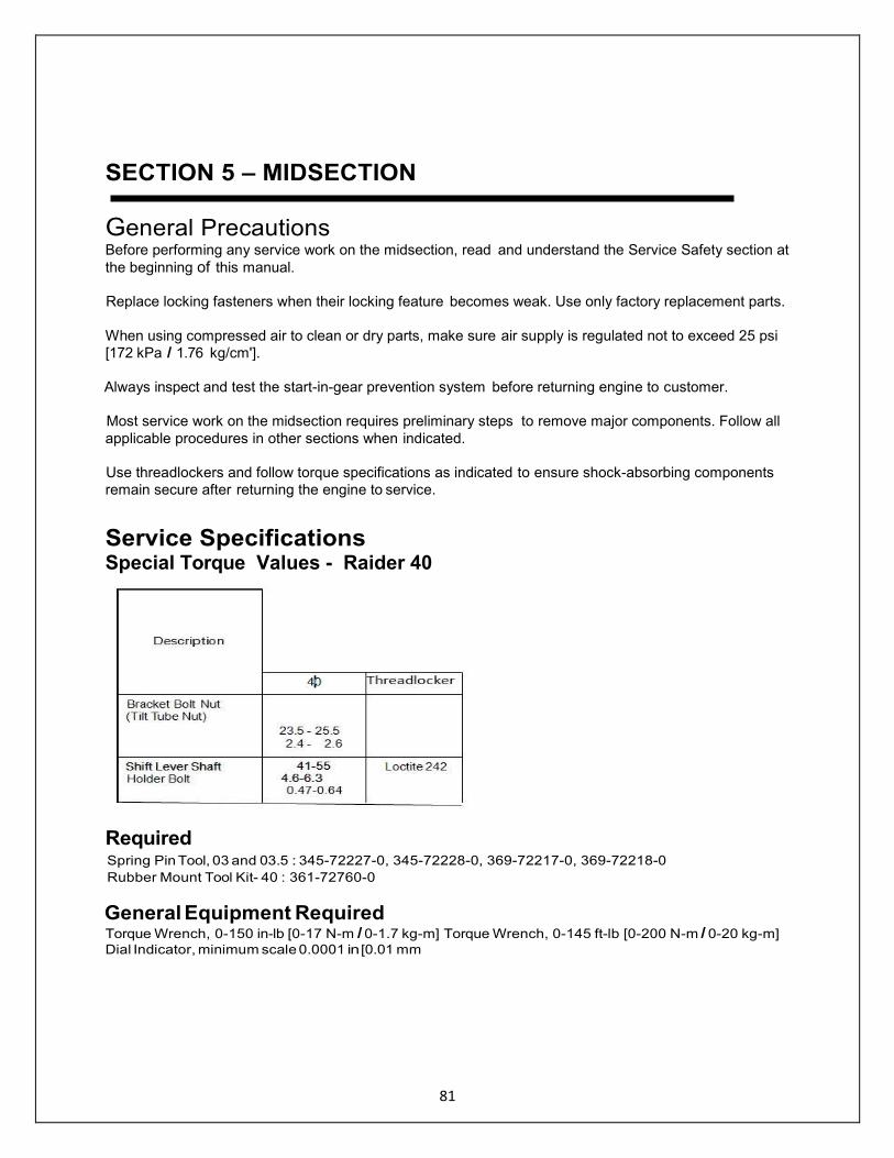
Service Specifications Special Torque Values - Raider 40
Required Spring Pin Tool, 03 and 03.5 : 345-72227-0, 345-72228-0, 369-72217-0, 369-72218-0
Rubber Mount Tool Kit- 40 : 361-72760-0
General Equipment Required Torque Wrench, 0-150 in-lb [0-17 N-m I 0-1.7 kg-m] Torque Wrench, 0-145 ft-lb [0-200 N-m I 0-20 kg-m]
Dial Indicator, minimum scale 0.0001 in [0.01 mm
82
Consumable Supplies Required Threadlocker, Loctite 242 Threadlocker, Loctite 243 Gasket Dressing, Permatex Hylomar Aerosol High-Temp Gasket Dressing Silicone Sealant, Permatex Hi-Temp RTV Silicone
Gasket Super Bond Adhesive,
Permatex Super Glue Gel
Cleaning Pads, Scotch-Brite® Abrasive Pads
lsopropyl Alcohol Cleaning Solvent Gasket Remover Genuine Grease or Equivalent Friction Surface Marine Grease
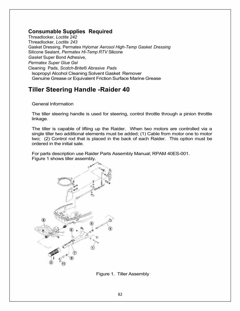
Tiller Steering Handle -Raider 40
General Information The tiller steering handle is used for steering, control throttle through a pinion throttle linkage. The tiller is capable of lifting up the Raider. When two motors are controlled via a single tiller two additional elements must be added; (1) Cable from motor one to motor two; (2) Control rod that is placed in the back of each Raider. This option must be ordered in the initial sale. For parts description use Raider Parts Assembly Manual; RPAM 40ES-001. Figure 1 shows tiller assembly.
Figure 1. Tiller Assembly
83
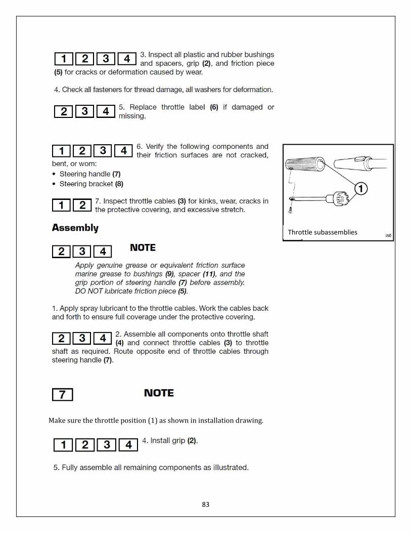
Make sure the throttle position (1) as shown in installation drawing.
Throttle subassemblies

84
Twist Handle and Linkage Assembly
Figure 2. Tiller Arm Subassemblies
85
86
87
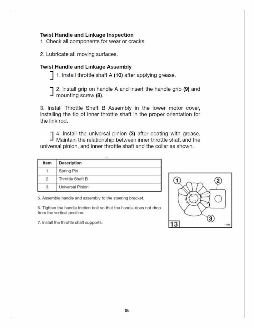
9
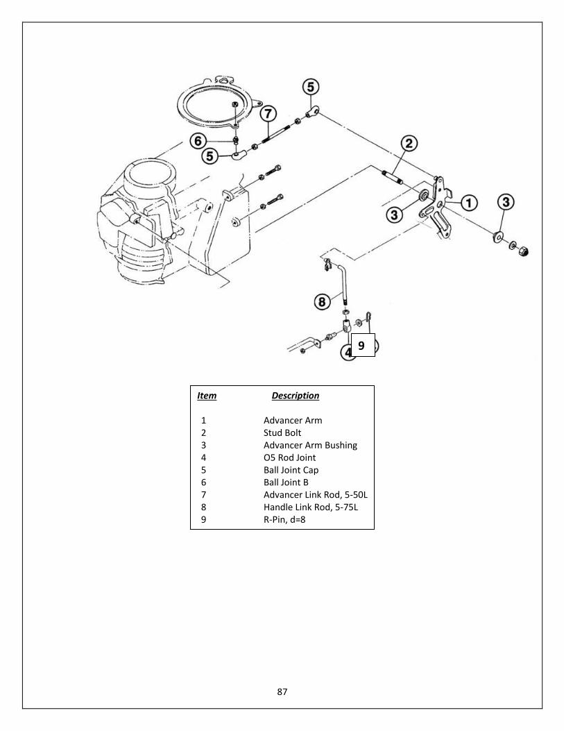
Item Description 1 Advancer Arm 2 Stud Bolt 3 Advancer Arm Bushing 4 O5 Rod Joint 5 Ball Joint Cap 6 Ball Joint B 7 Advancer Link Rod, 5-50L 8 Handle Link Rod, 5-75L 9 R-Pin, d=8

88

89
1. Turn the handle grip so that the collar center of the carburetor throttle lever in on the “S” marking line.
2. Adjust the length of the handle link rod so that the START match mark on the handle grip is aligned to the START position on the tiller handle.
BTDC 25 degrees

90
Timing Set at: ATDC 2 degrees

91
TI657
To Shifter
7
8
9
92
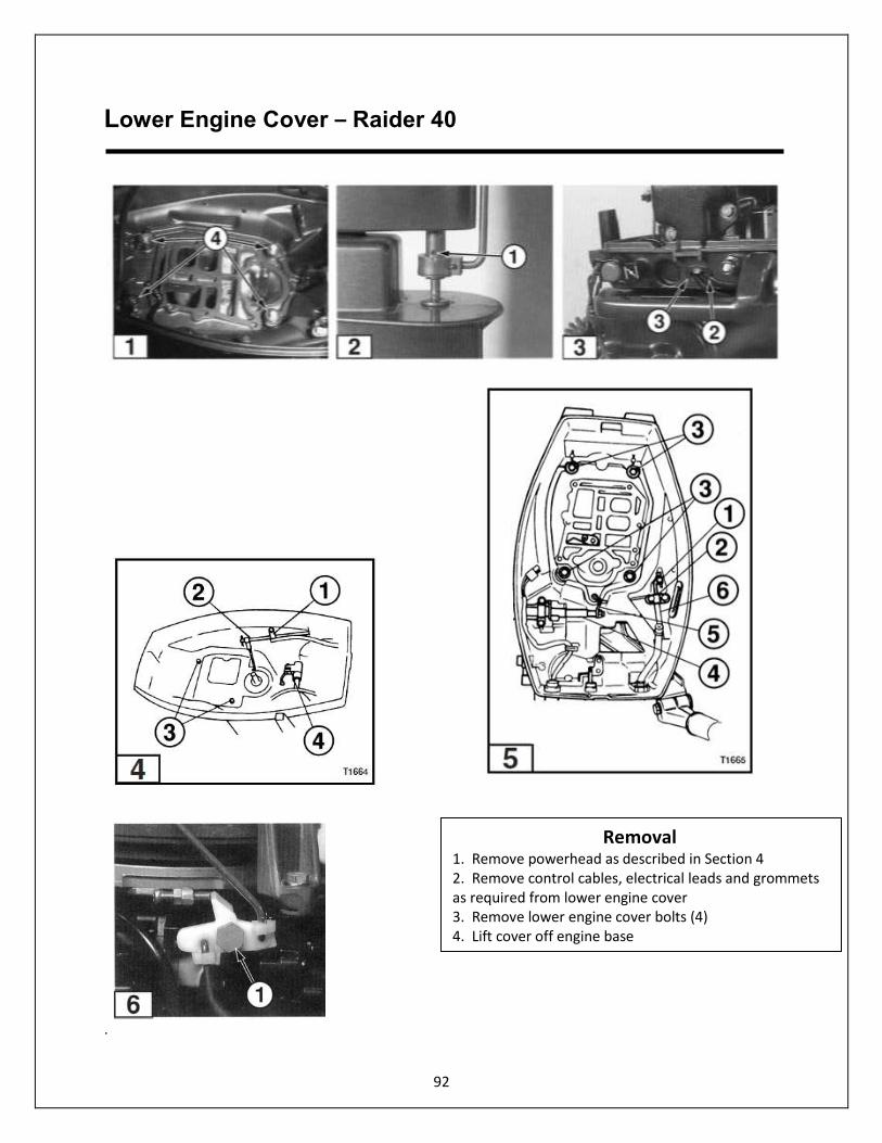
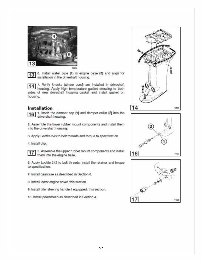
Lower Engine Cover – Raider 40
.
Removal 1. Remove powerhead as described in Section 4 2. Remove control cables, electrical leads and grommets as required from lower engine cover 3. Remove lower engine cover bolts (4) 4. Lift cover off engine base

93

94
95

96
97
98
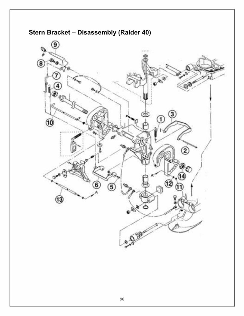
Stern Bracket – Disassembly (Raider 40)
99
Stern Bracket – Disassembly
1. Remove the reverse lock spring (1) 2. Remove the split pin from the reverse lock rod (2) and remove the reverse lock rod (2) and reverse lock (3). 3. Remove the reverse lock lever spring (4) 4. Remove the reverse lock arm shafts (5) and remove the reverse lock arm (6). 5. Remove the reverse lock link (7). 6. Remove the reverse lock lever shafts (8) and remove the reverse lock lever (9). 7. Remove the thrust rod (10). 8. Remove the bracket distance piece nuts (11) and washer (12) and pull out the bracket distance piece (13) 9. Remove the bracket nut (14) and separate the brackets.
Swivel Bracket and Reverse Lock
Raider 40 Swivel Bracket Reverse lock Turning Radius 80 degrees Lock all of shifting positions Port: 40 degrees Unlocking is carried out by
Starboard: 40 degrees Operating the reverse lock lever.
100
SECTION 6 - GEARCASE General Precautions Before performing any service work on the gearcase, read and understand the Service Safety section at
the beginning of this manual.
Full servicing of the gearcase requires manufacturer special tools. Follow all special tool requirements as
specified. Substituting special tools with those not provided by the manufacturer may result in severe
personal injury, equipment or engine damage, or faulty service work.
Perform bearing removal and installation operations exactly as specified to avoid damage to the bearing or housing during pressing operations.
Replace locking fasteners when their locking feature becomes weak. Use only factory replacement parts. When using compressed air to clean or dry parts, make sure air supply is regulated not to exceed 25 psi
[172 kPa I 1.76 kg/cm'].
101
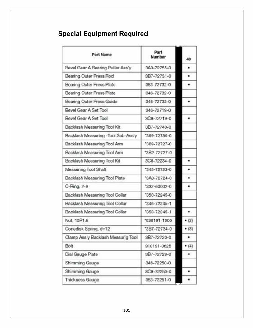
Special Equipment Required

102
General Equipment Required Torque Wrench, 0-150 in lb (0-17/0-1.7 kg-m) Torque Wrench, 0-150 ft-lb (0-200 N-m / 0-20 kg-m) Dial Indicator, minimum scale 0.0001 in (0.01 mm) Gearcase Pressure Tester, Stevens S-34 or equivalent Gearcase Vacuum Tester, Stevens V-34 or equivalent Seal Pullers Seal Installers Heat Gun
103
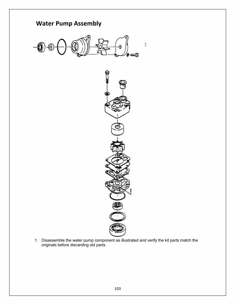
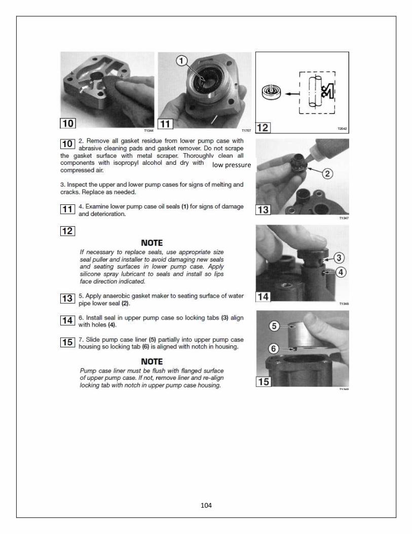
1. Disassemble the water pump component as illustrated and verify the kit parts match the
originals before discarding old parts.
Water Pump Assembly
104
low pressure

105

106
107
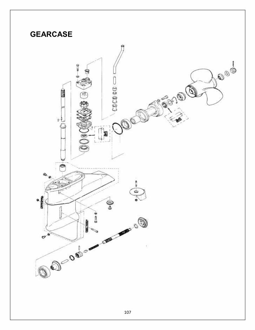
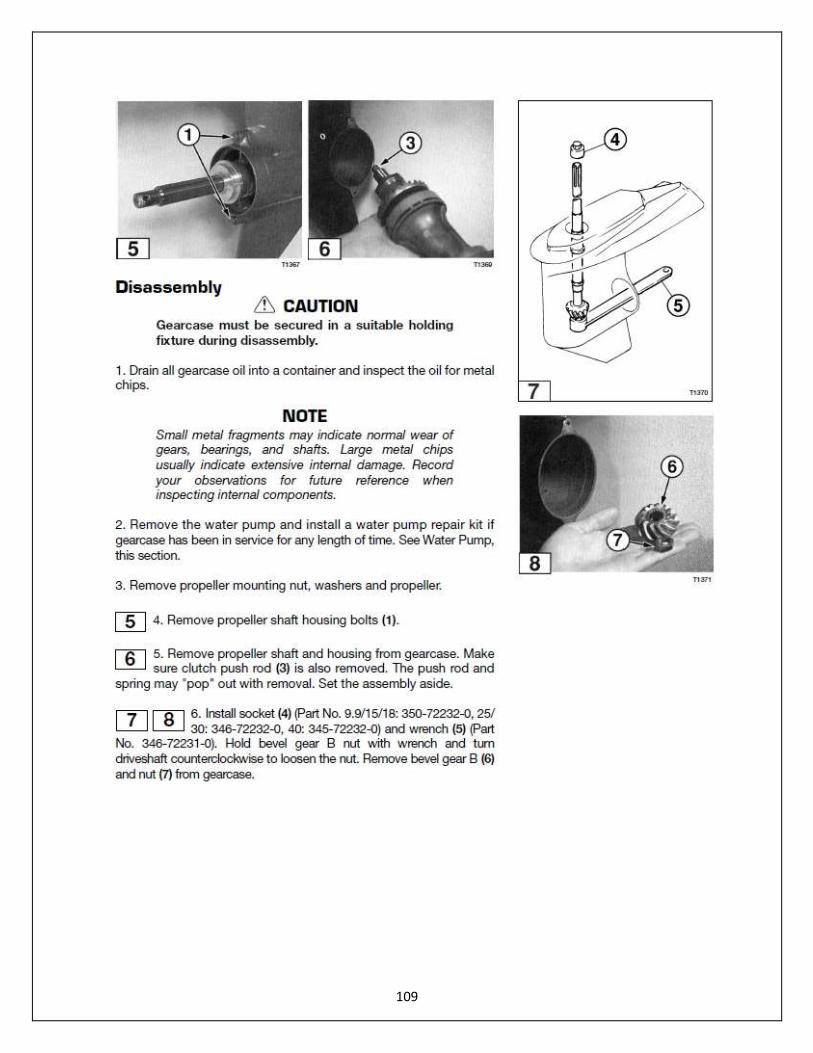
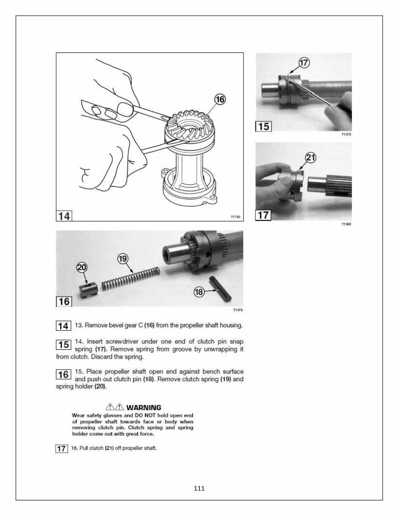
GEARCASE
108
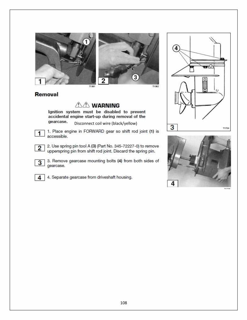
Disconnect coil wire (black/yellow)
109

110
111
112
113
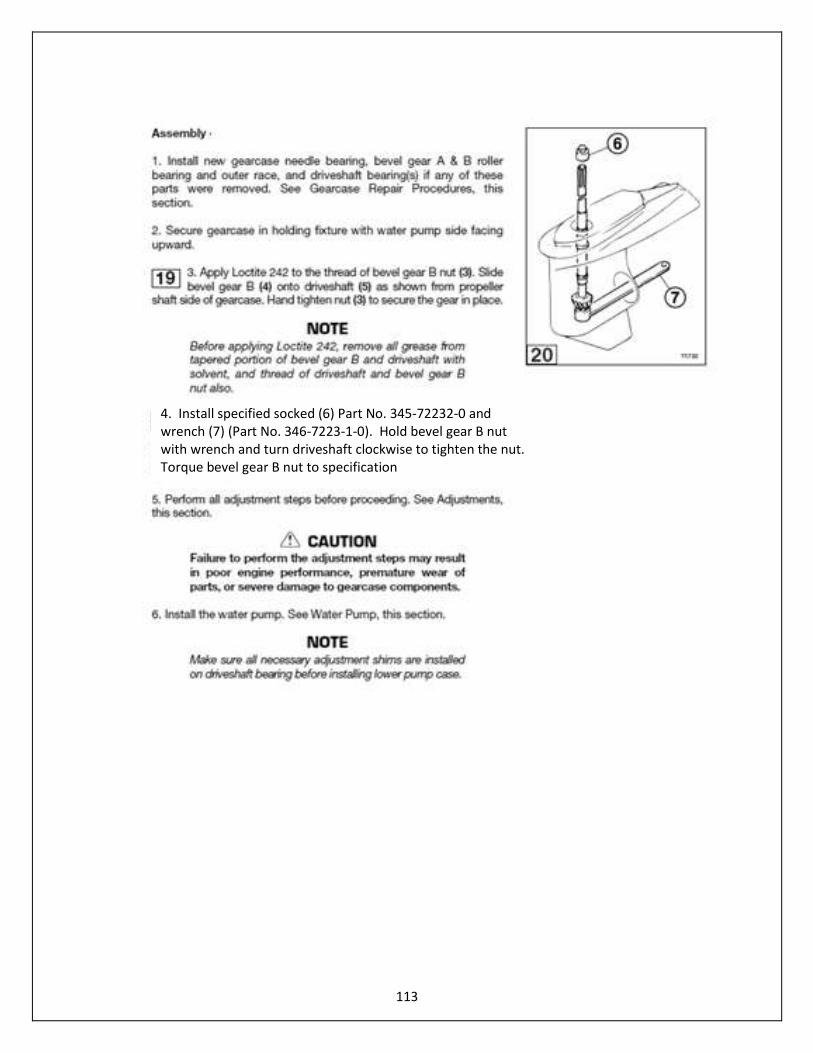
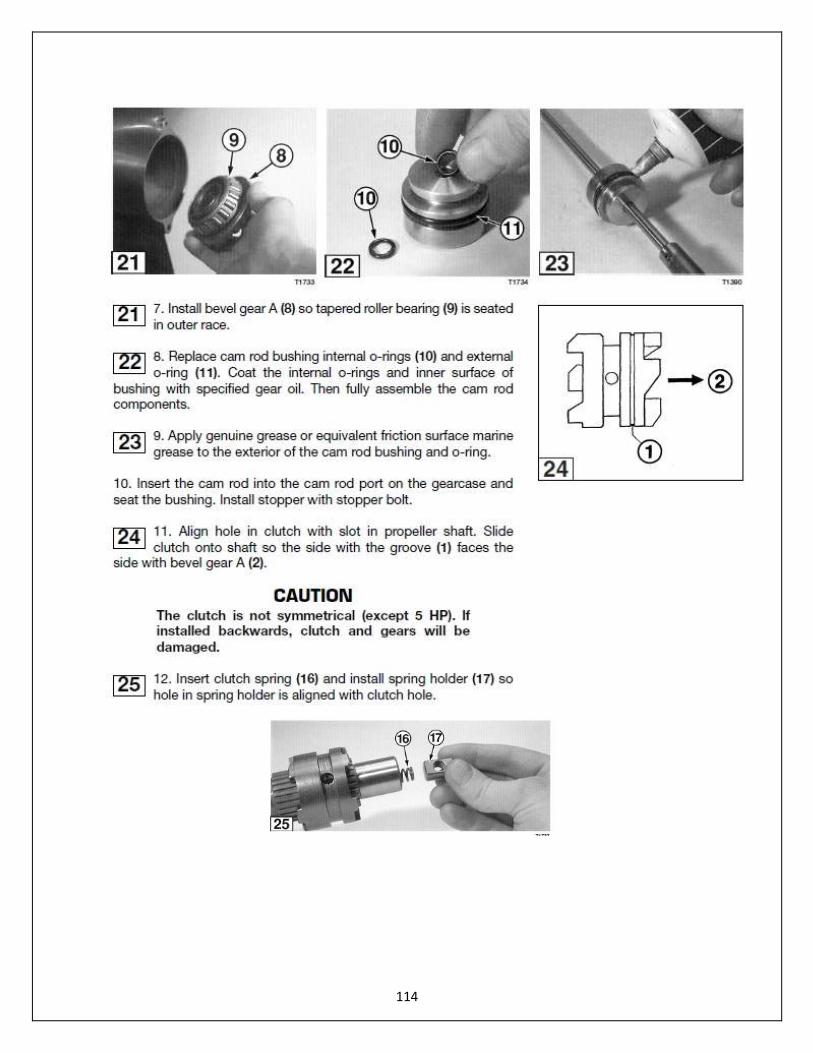
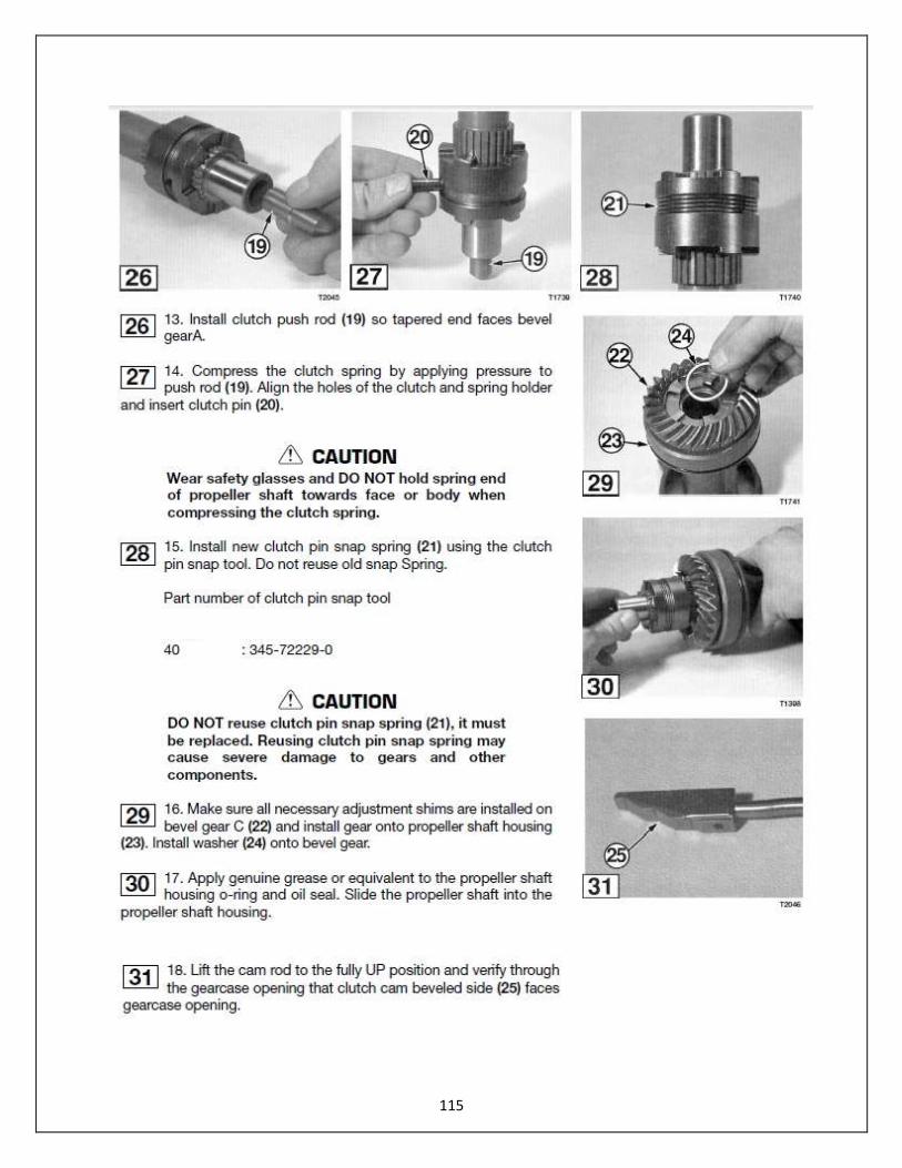
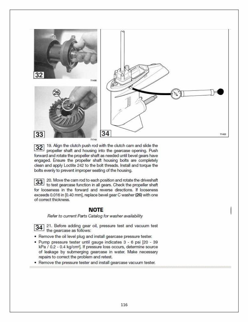
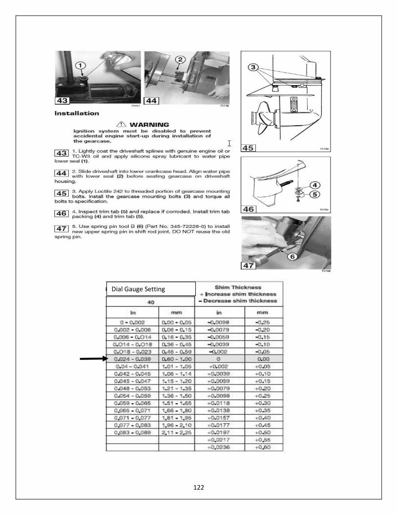
4. Install specified socked (6) Part No. 345-72232-0 and wrench (7) (Part No. 346-7223-1-0). Hold bevel gear B nut with wrench and turn driveshaft clockwise to tighten the nut. Torque bevel gear B nut to specification
114
115
116
117

118
119
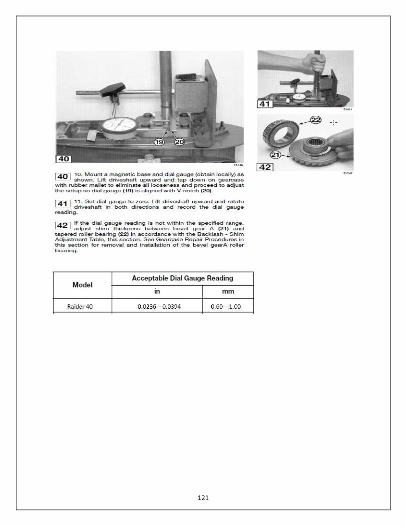
Backlash
Special tools are required for measuring backlash. The following describes how to measure and correct backlash in the Raider 40 outboard.

120
121
122
Dial Gauge Setting
123
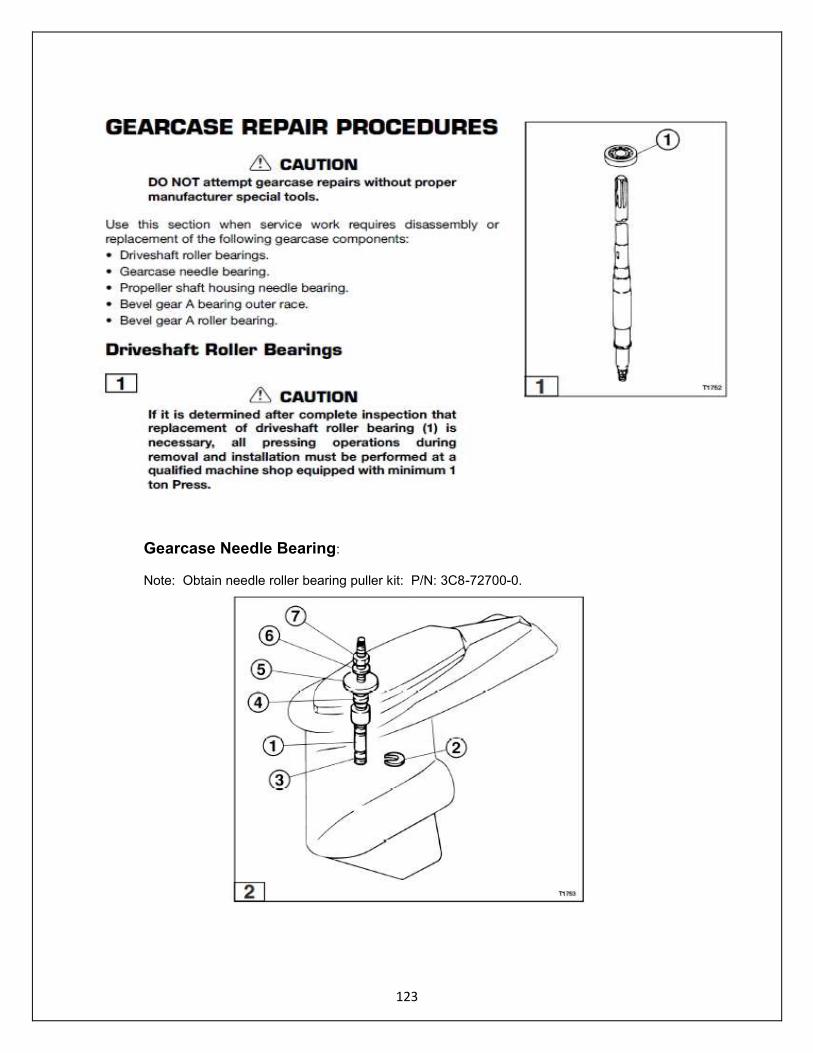
Gearcase Needle Bearing:
Note: Obtain needle roller bearing puller kit: P/N: 3C8-72700-0.
124

125
126
127
128
SECTION 7 – ELECTRICAL SYSTEM
General Precautions Before performing any service work on the electrical system, read and understand the Service Safety section at the beginning of this manual.
Use the manufacturer and special tools as indicated during servicing of the electrical system.
Avoid electrical shock:
• Do not handle spark gap tester leads during performance testing. • Do not touch ignition coils, exciter coil, pulser coils, or alternator coils while the engine is cranking or
running.
Use the spark gap tester to prevent the engine from starting when performing static ignition performance tests. Use caution when performing tests with the engine cover removed. Do not wear loose clothing or jewelry. Keep hair, hands, and clothing away from the flywheel and other moving parts.
After repairs are complete, make sure all ignition and electrical leads are properly routed and clamped in their original positions.
Replace locking fasteners when their locking feature becomes weak. Use only factory replacement parts. Always inspect and test the start-in-gear prevention system before returning engine to customer.
129
General Precautions Before performing any service work on the Raider electrical system, read and understand the Service Safety section at the beginning of this Service Manual. Use the manufacturer and special tools as indicated during servicing of the electrical system. Avoid electrical shock:
Do not handle spark gap tester during performance testing.
Do not tough ignition coils, exciter coil, pulser coils or alternator coils while engine is cranking or running.
Use the spark gap tester to prevent the engine from starting when performing static ignition performance tests. Use caution when performing tests with the engine cowling removed. Do not wear loose clothing or jewelry. Keep hair, hands, and clothing away from the flywheel and other moving parts. After repairs are complete, make sure all ignition and electrical leads are properly routed and clamped in their original positions. Replace locking fasteners when their locking feature becomes weak. Use only COTS factory parts (Mercury, Nissan or Tohatsu) or Raider replacement parts. Always inspect and test the start-in-gear prevention system before returning engine to mission readiness. Always disconnect battery when not in use.

130
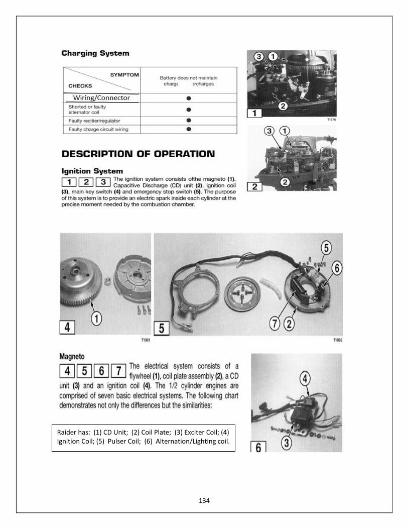
Electrical System - Overview Ignition Type: Flywheel Magneto Capacitor Discharge Ignition Timing: Before Top Dead Center (BTDC) – 25 Degrees ATDC – 2 Degrees Spark Plug: Pulstar – Model SBE 1/10 Spark Plug Gap: .033 (No larger than .050) Battery: Part No. 365-265-001 (Raider sealed Lithium Iron – 265 CA) Alternator: 12V 80W Charging Performance @ 5500 – 5 Amps Ignition Coil Resistance – Primary Coil: 0.2 – 0.3 KOhms Secondary Coil: 4.1 – 6.1 K Ohms CD Unit Output (Cranking): 198-220 DVA Exciter Coil Output (Cranking): 100 DVA Mim Pulser Coil Output (Cranking): 4.75 – 5.0 DVA Coil Resistance – Exciter Coil: 130-195 Ohms Alternator W-Y: Y-W 0.65 - 0.98 Y-B 0.31 – 0.47 W-B – 0.37 – 0.55
131
132
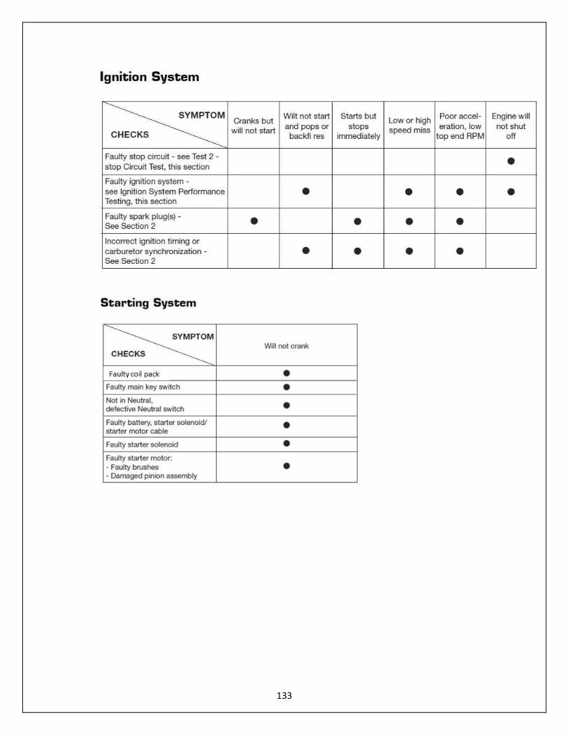
Troubleshooting - Electrical
133
134
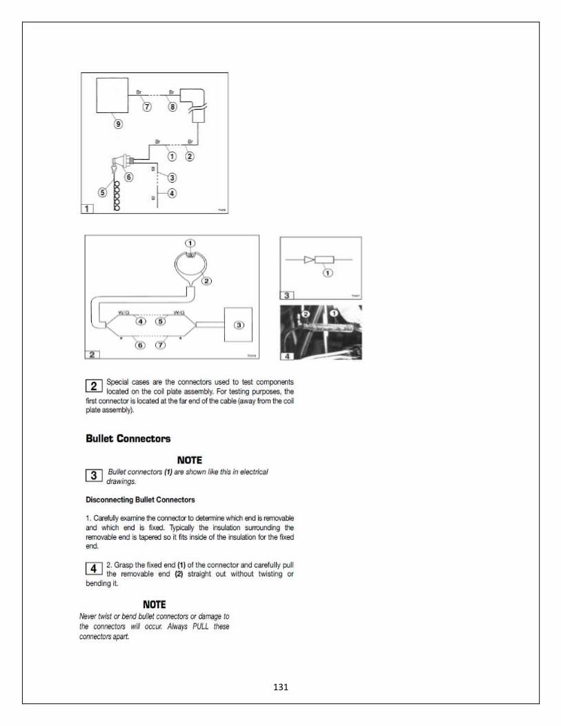
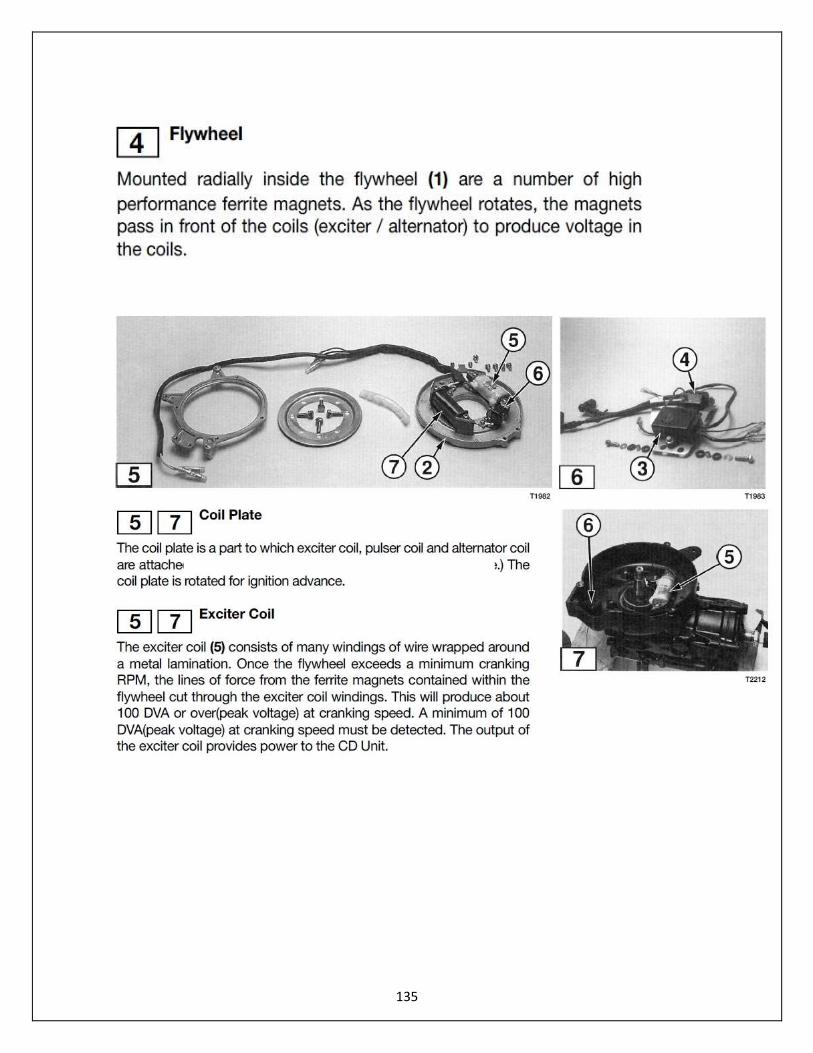
Raider has: (1) CD Unit; (2) Coil Plate; (3) Exciter Coil; (4) Ignition Coil; (5) Pulser Coil; (6) Alternation/Lighting coil.
135
136

137
Battery Care and Maintenance
The Raider 40 outboard motor has a battery located internal, located under the cowling. This battery is a fully sealed lithium-iron battery shown below.
138
The battery has one plug with two connectors (+) and (-). It is constructed that it can be plugged into the mating connector one way. Battery Size: Length: 5.83 inches x Width 2.63 x Height 4.13 inches Weight: 2.5 pounds Cold Cranking Amps: 270 Polarity: (+) (-) Charging System: Output of 13.1 Volts Lithium-iron: 18 Ah PbEq 12V; eq, “L” polarity, Sealed Fastening System: Slot in base of battery receptacle; single screw at top.
General Procedures - Inspection
Inspect battery case for damage Inspect connector for corrosion Inspect cables Check battery mounting
Cleaning Disconnect and remove battery Clean battery, connectors - Wash with water and let dry Place dielectric grease on both sides of connector Replace battery, tighten screw. Do not plug in connector until ready for use
All cranking output tests must be performed with spark plugs installed and torque in the cylinder head. If necessary to remove the spark plugs, be sure to keep the spark gap tester away from open spark plug holes
139
When repairs are complete; make sure all ignition and electrical Leads are properly routed and clamped in their original systems And the in-gear prevention system must be tested prior to delivering to units.
If you have problems stopping Raider outboard proceed directly to test 2 – Stop Circuit Test

140
Ignition System Performance Testing Flow Chart
141
142
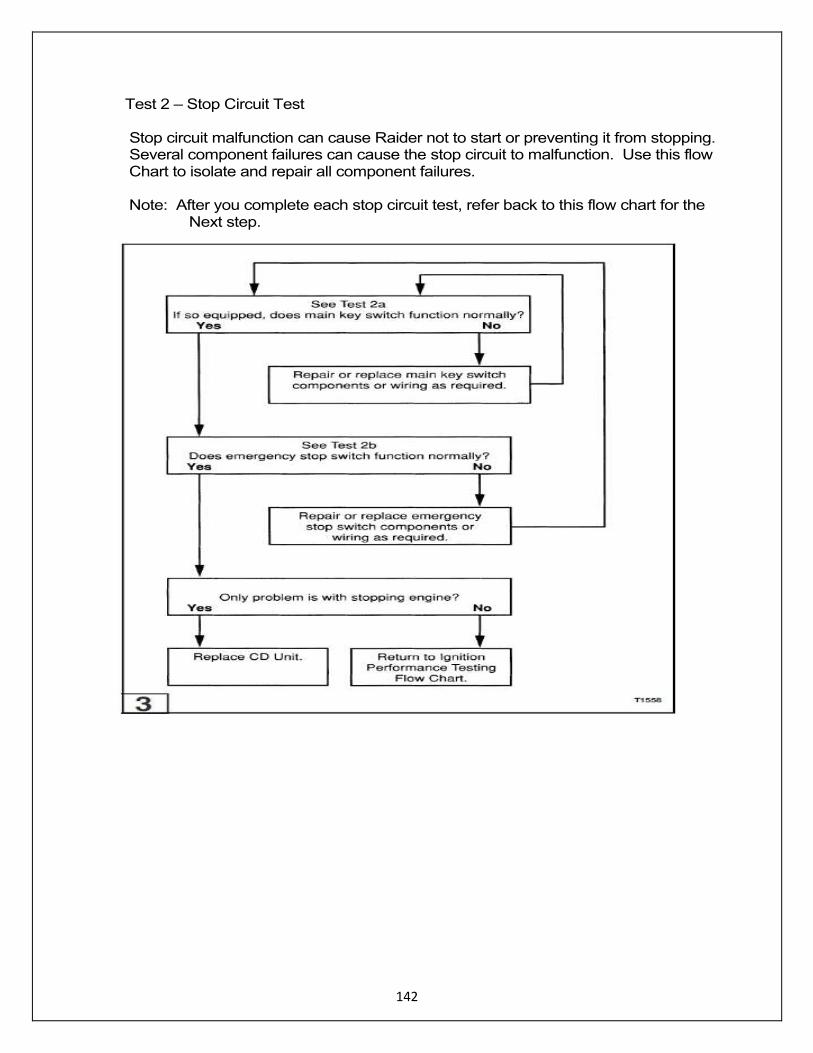
Test 2 – Stop Circuit Test Stop circuit malfunction can cause Raider not to start or preventing it from stopping. Several component failures can cause the stop circuit to malfunction. Use this flow Chart to isolate and repair all component failures. Note: After you complete each stop circuit test, refer back to this flow chart for the Next step.

143
Test 2b. Stop Circuit Emergency Stop Switch Test
The emergency stop switch test is used to determine whether it is functioning normally. Note: Make sure all electrical terminals are connected during this test except those that are noted in the test procedure. Check for continuity between chassis ground and the ground connection for the magneto plate, CD Unit, and ignition coils before conducting the following procedure. All continuity tests must be conducted or you may damage the meter. Remove plug from Raider battery.
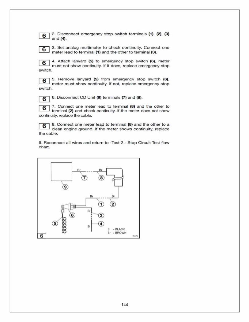
144
145
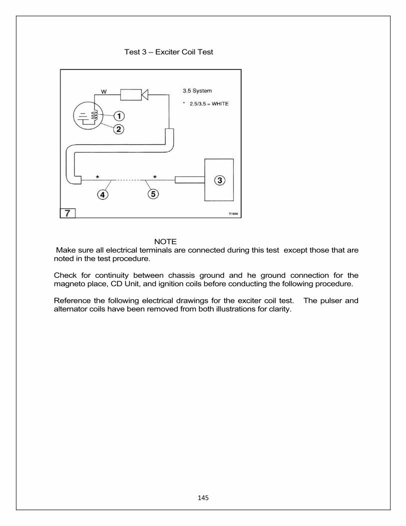
Test 3 – Exciter Coil Test
NOTE Make sure all electrical terminals are connected during this test except those that are noted in the test procedure. Check for continuity between chassis ground and he ground connection for the magneto place, CD Unit, and ignition coils before conducting the following procedure. Reference the following electrical drawings for the exciter coil test. The pulser and alternator coils have been removed from both illustrations for clarity.
146
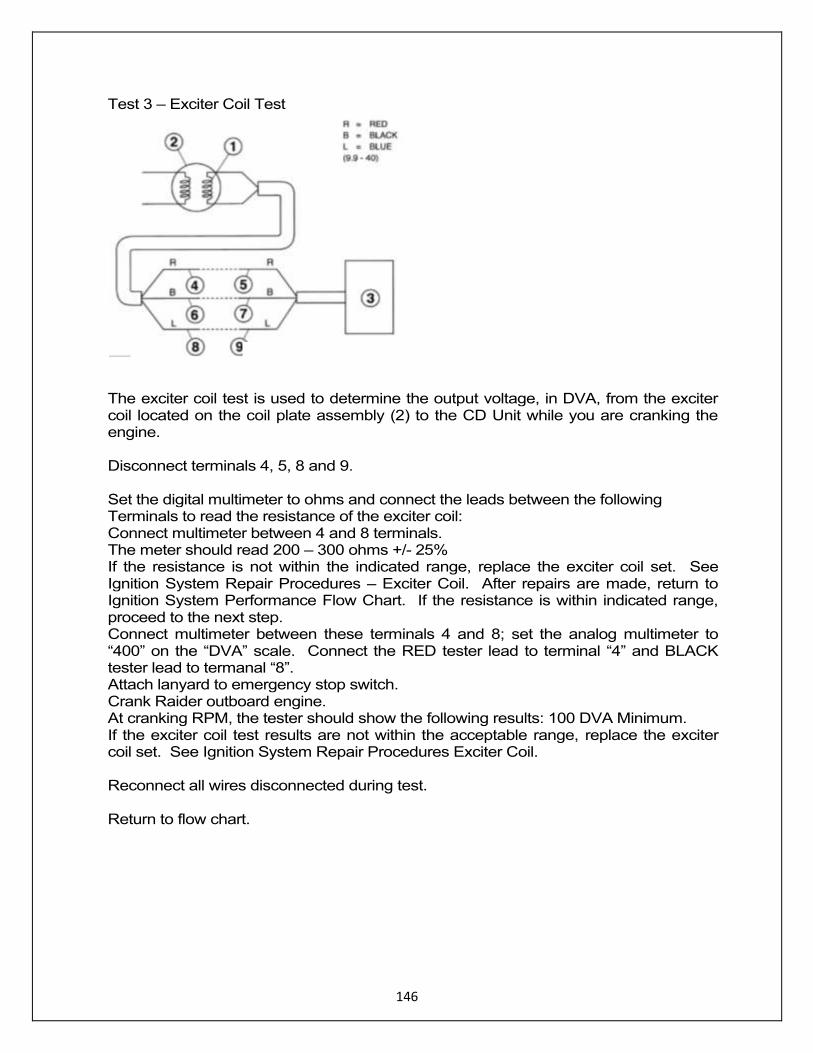
Test 3 – Exciter Coil Test
The exciter coil test is used to determine the output voltage, in DVA, from the exciter coil located on the coil plate assembly (2) to the CD Unit while you are cranking the engine. Disconnect terminals 4, 5, 8 and 9. Set the digital multimeter to ohms and connect the leads between the following Terminals to read the resistance of the exciter coil: Connect multimeter between 4 and 8 terminals. The meter should read 200 – 300 ohms +/- 25% If the resistance is not within the indicated range, replace the exciter coil set. See Ignition System Repair Procedures – Exciter Coil. After repairs are made, return to Ignition System Performance Flow Chart. If the resistance is within indicated range, proceed to the next step. Connect multimeter between these terminals 4 and 8; set the analog multimeter to “400” on the “DVA” scale. Connect the RED tester lead to terminal “4” and BLACK tester lead to termanal “8”. Attach lanyard to emergency stop switch. Crank Raider outboard engine. At cranking RPM, the tester should show the following results: 100 DVA Minimum. If the exciter coil test results are not within the acceptable range, replace the exciter coil set. See Ignition System Repair Procedures Exciter Coil. Reconnect all wires disconnected during test. Return to flow chart.
147
Test 4. Raider Pulser Coil Test
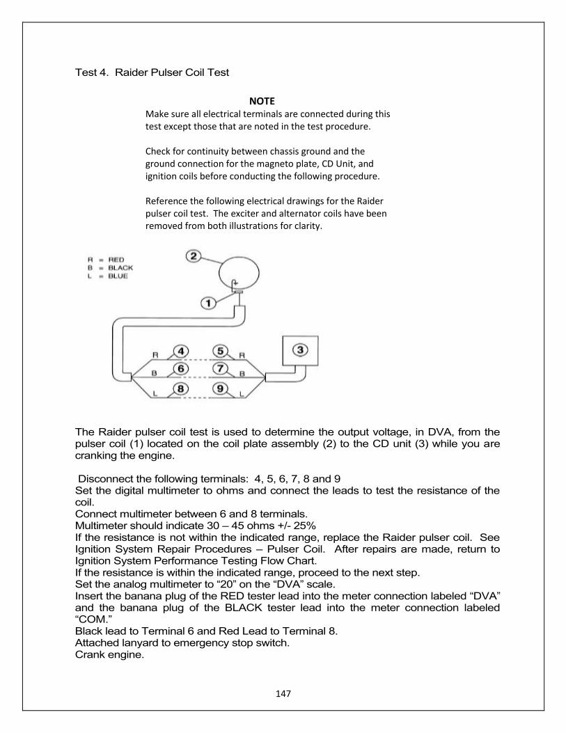
The Raider pulser coil test is used to determine the output voltage, in DVA, from the pulser coil (1) located on the coil plate assembly (2) to the CD unit (3) while you are cranking the engine. Disconnect the following terminals: 4, 5, 6, 7, 8 and 9 Set the digital multimeter to ohms and connect the leads to test the resistance of the coil. Connect multimeter between 6 and 8 terminals. Multimeter should indicate 30 – 45 ohms +/- 25% If the resistance is not within the indicated range, replace the Raider pulser coil. See Ignition System Repair Procedures – Pulser Coil. After repairs are made, return to Ignition System Performance Testing Flow Chart. If the resistance is within the indicated range, proceed to the next step. Set the analog multimeter to “20” on the “DVA” scale. Insert the banana plug of the RED tester lead into the meter connection labeled “DVA” and the banana plug of the BLACK tester lead into the meter connection labeled “COM.” Black lead to Terminal 6 and Red Lead to Terminal 8. Attached lanyard to emergency stop switch. Crank engine.
NOTE Make sure all electrical terminals are connected during this test except those that are noted in the test procedure. Check for continuity between chassis ground and the ground connection for the magneto plate, CD Unit, and ignition coils before conducting the following procedure. Reference the following electrical drawings for the Raider pulser coil test. The exciter and alternator coils have been removed from both illustrations for clarity.
148
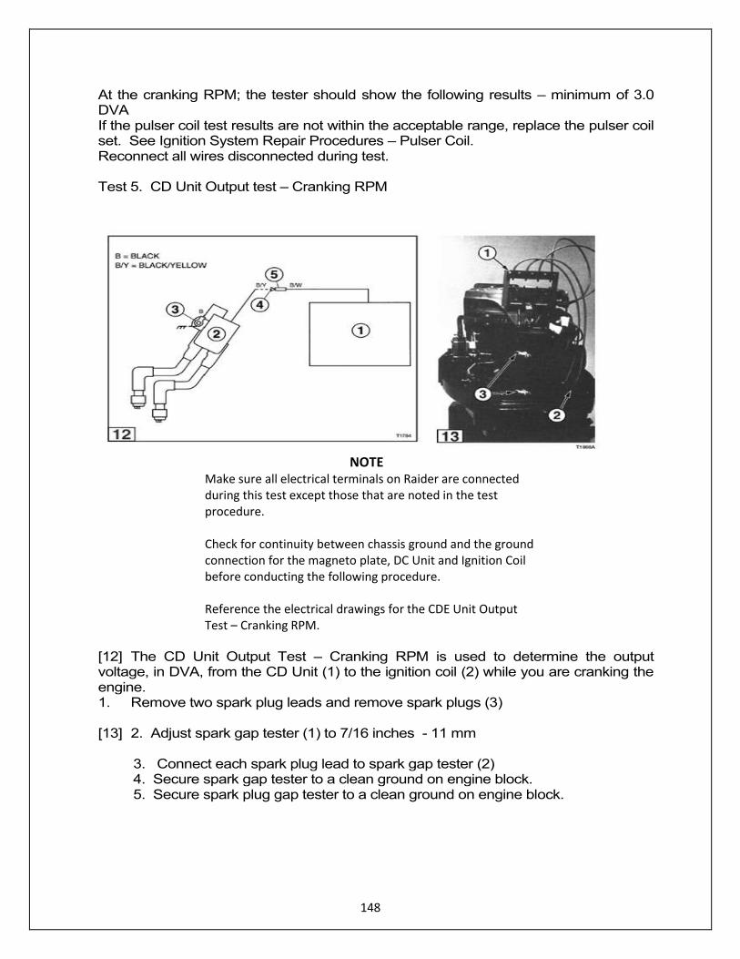
At the cranking RPM; the tester should show the following results – minimum of 3.0 DVA If the pulser coil test results are not within the acceptable range, replace the pulser coil set. See Ignition System Repair Procedures – Pulser Coil. Reconnect all wires disconnected during test. Test 5. CD Unit Output test – Cranking RPM
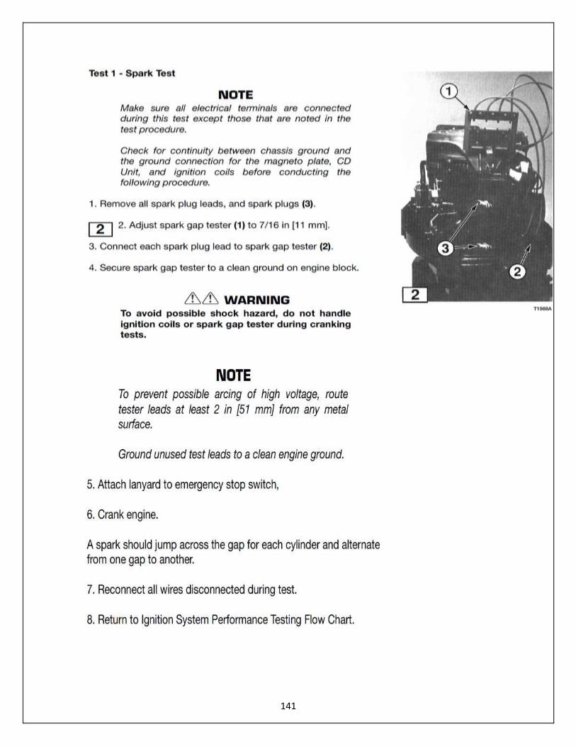
[12] The CD Unit Output Test – Cranking RPM is used to determine the output voltage, in DVA, from the CD Unit (1) to the ignition coil (2) while you are cranking the engine. 1. Remove two spark plug leads and remove spark plugs (3) [13] 2. Adjust spark gap tester (1) to 7/16 inches - 11 mm 3. Connect each spark plug lead to spark gap tester (2) 4. Secure spark gap tester to a clean ground on engine block. 5. Secure spark plug gap tester to a clean ground on engine block.
NOTE Make sure all electrical terminals on Raider are connected during this test except those that are noted in the test procedure. Check for continuity between chassis ground and the ground connection for the magneto plate, DC Unit and Ignition Coil before conducting the following procedure. Reference the electrical drawings for the CDE Unit Output Test – Cranking RPM.
149
To avoid possible shock hazard, do not handle Ignition coils or spark gap tester during cranking tests. NOTE To prevent possible arcing of high voltage, route tester leads At least 2 inches from any metal surface. Ground unused test leads to a clean engine ground. 5. Set the tested to “400” on the “DVA” scale. Insert the banana plug of the RED tester head into the meter connection labeled “DVA” and the banana plus of the BLACK tester lead into the meter connection labeled “-COM.” Connect the BLACK tester lead to terminal (3). [12] 8. Carefully slide the RED tester into the bullet connector (terminal 4) sleeve until it makes contact with the terminal. 9. Attach lanyard to emergency stop switch. 10. Crank engine At cranking RPM, the tester should show the following result for each CD Unit output – 100 DVA minimum. If the test results for any CD Unit output is not within acceptable range, replace the CED Unit. See Ignition System Repair Procedures – CD Unit.
Reconnect all wires disconnected during test.
Return to flow chart.
NOTE DO NOT disconnect the CD Unit output connector (terminals (4) and (8). Damage to the CD Unit may result.
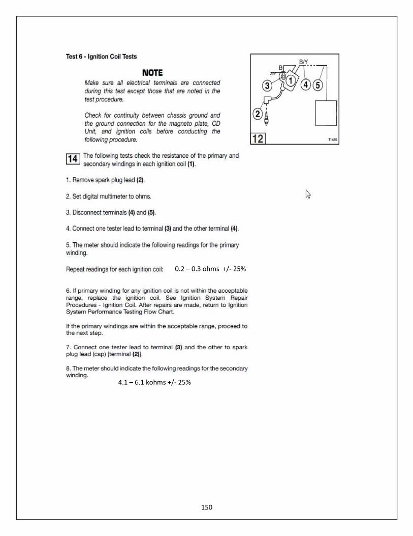
150
0.2 – 0.3 ohms +/- 25%
4.1 – 6.1 kohms +/- 25%
151
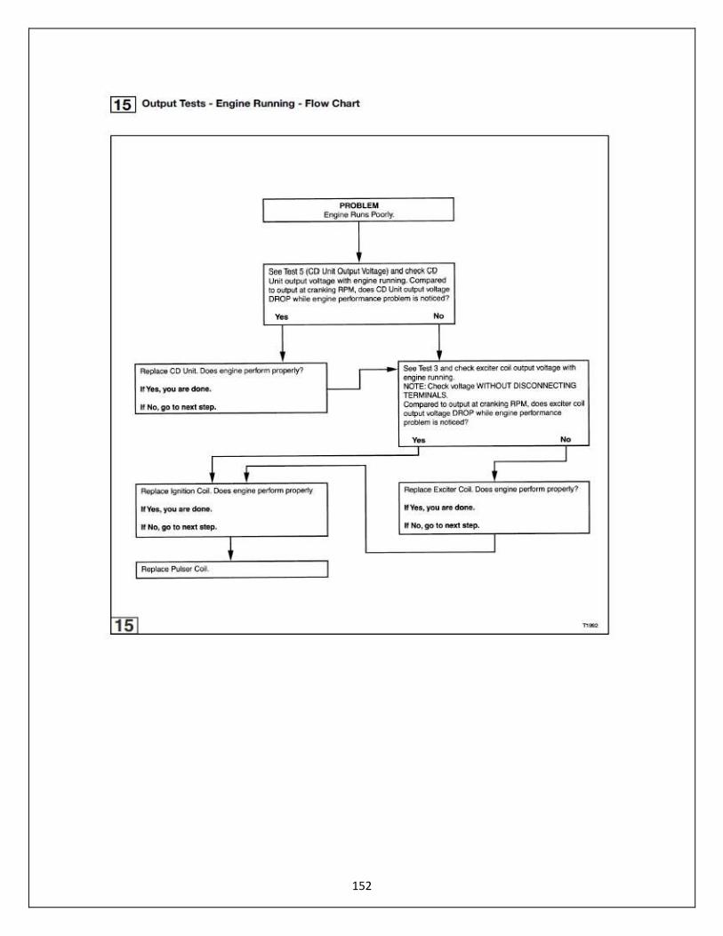
152
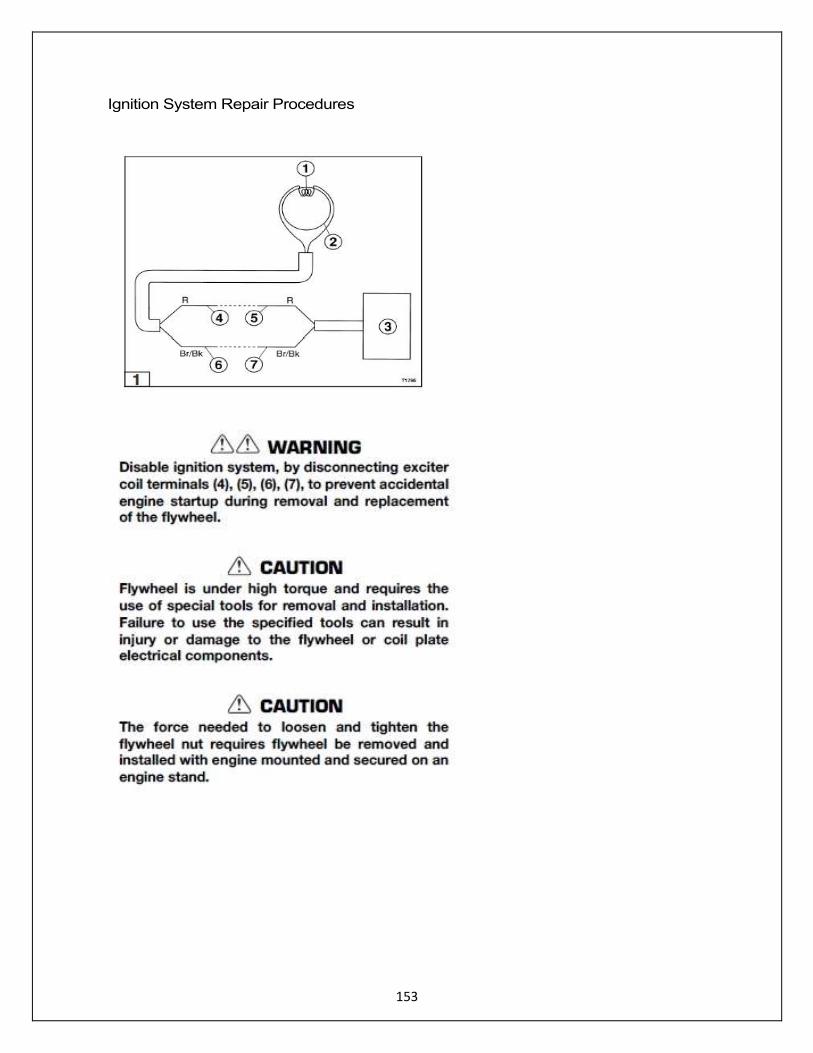
153
Ignition System Repair Procedures

154

155

156
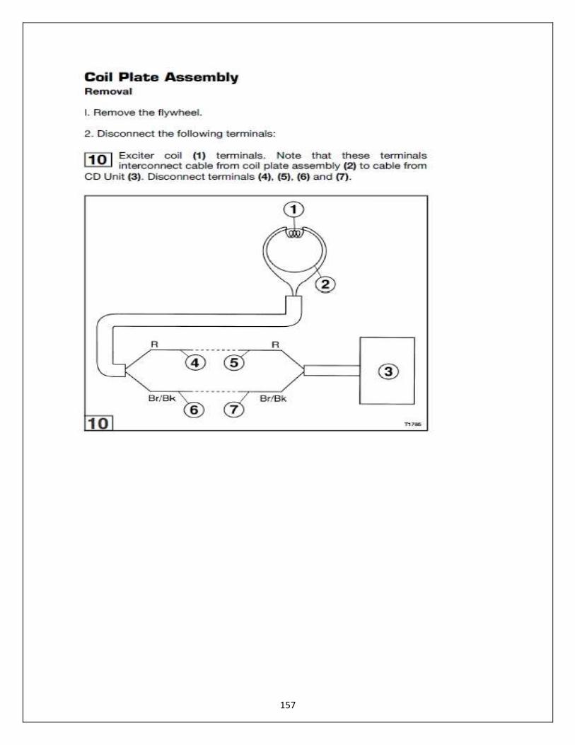
157
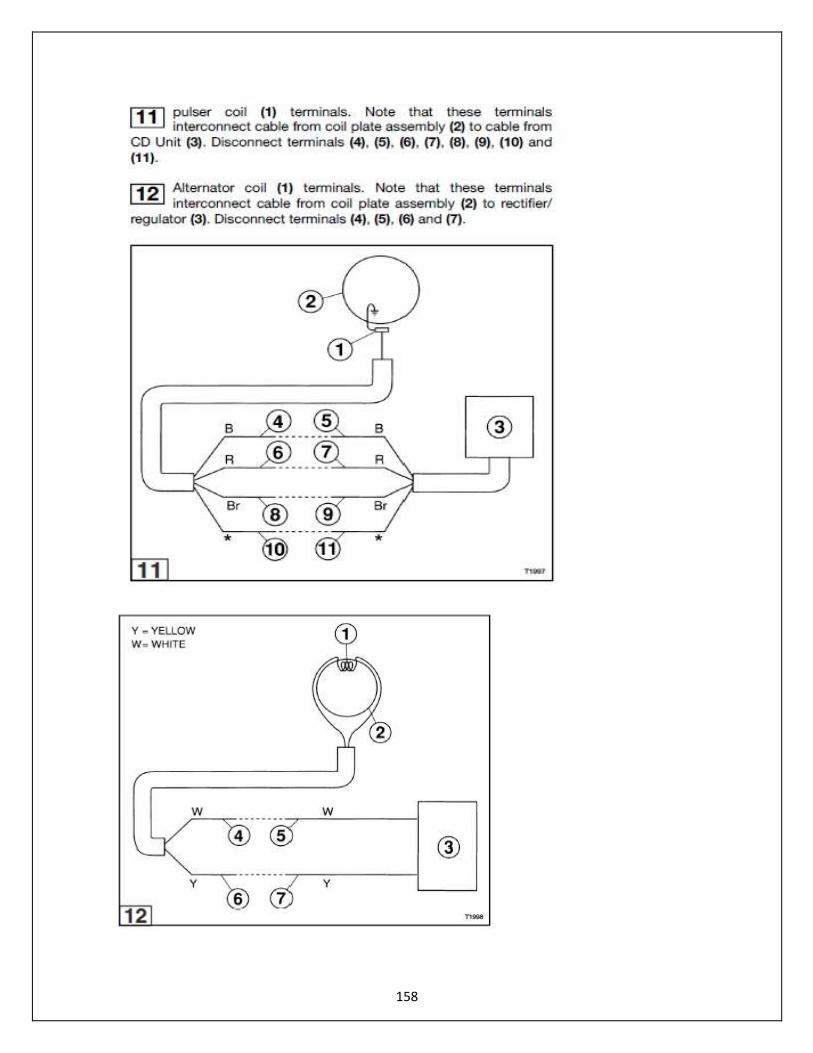
158
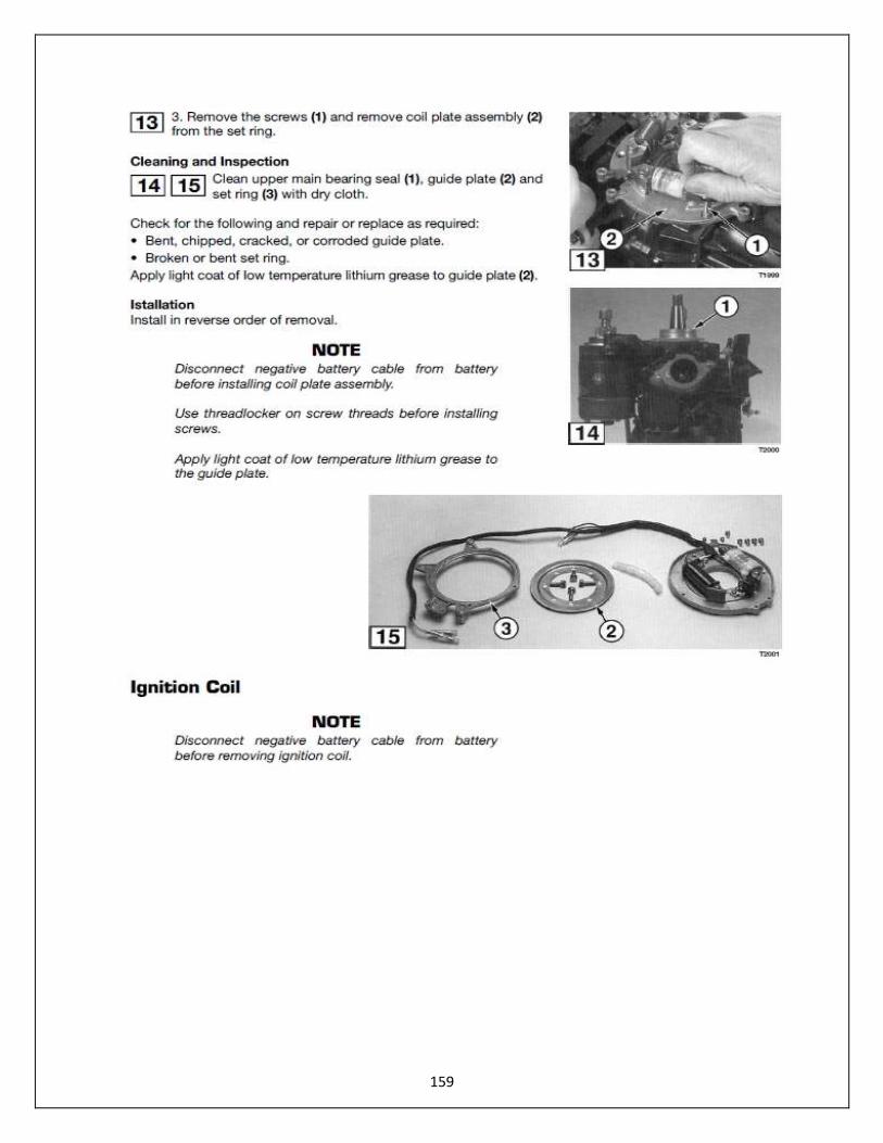
159

160
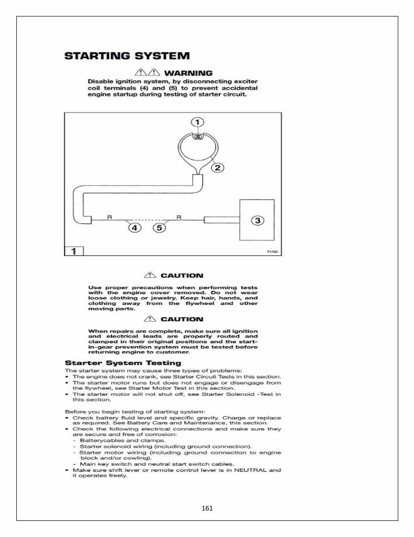
161
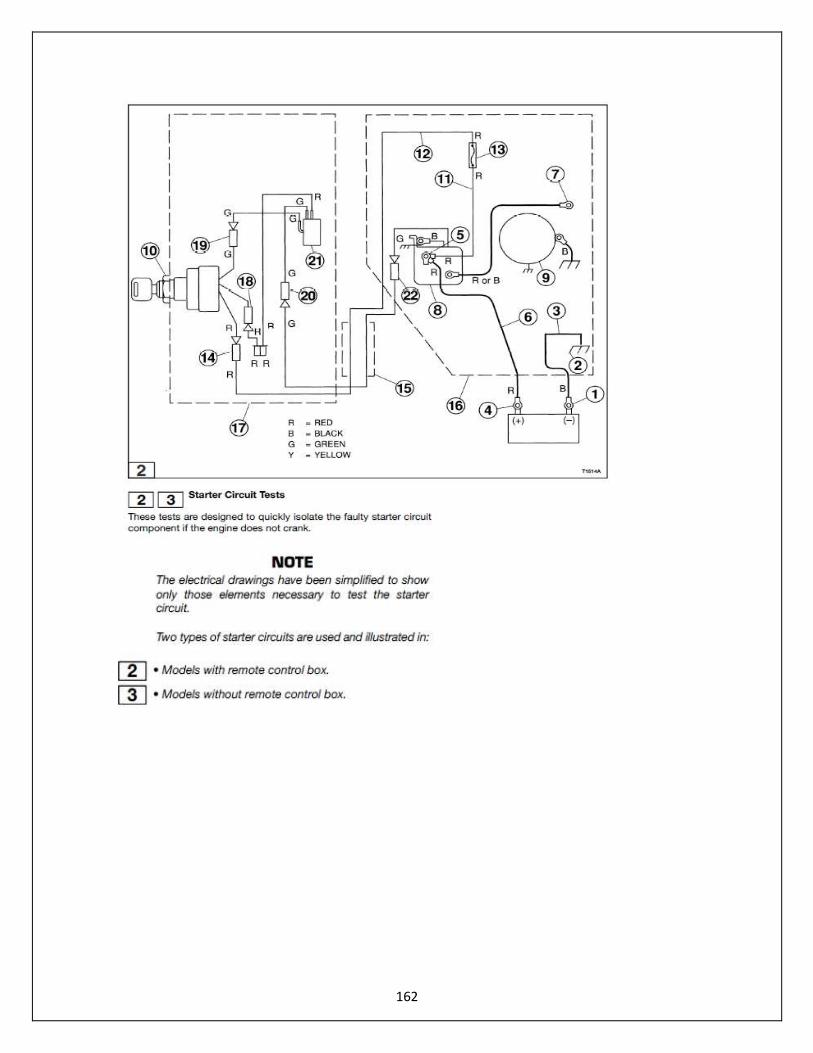
162

163
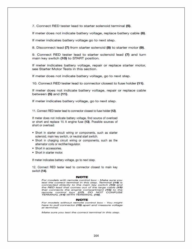
164
165
If meter does not indicate battery voltage, repair or replace cable between (12) and (14). If meter indicates battery voltage, go to next step. 13. Connect RED tester lead to main button starter switch and push Raider start button.
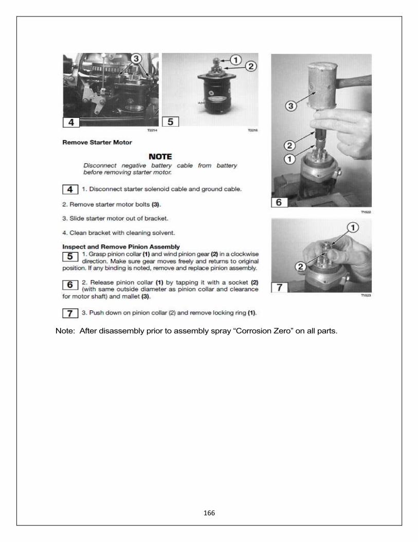
166
Note: After disassembly prior to assembly spray “Corrosion Zero” on all parts.
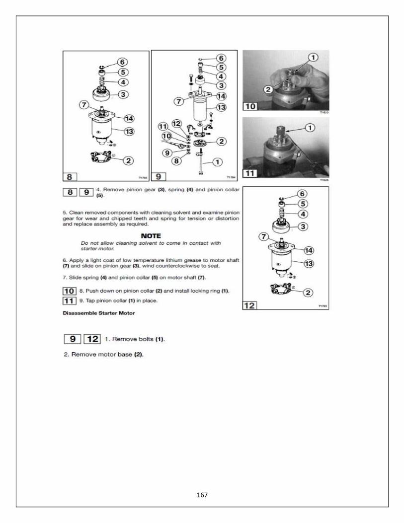
167

168
The Raider 40 Original Length (a) is 0.295 inches (7.5 mm). Repair Limit (b) is 0.177 inches (4.5 mm).

169
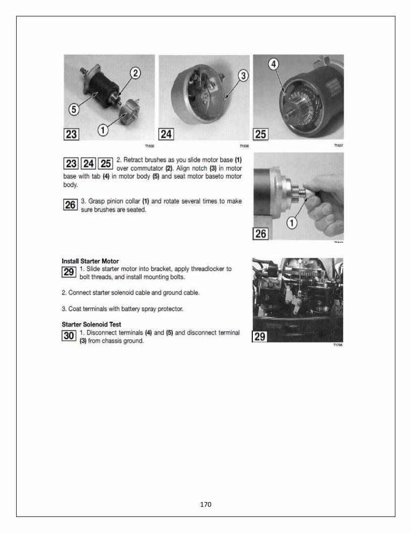
170
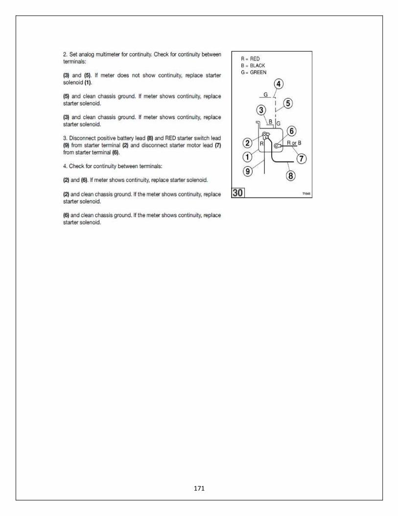
171

172
Note: Black (B is 2); White (W is 3); Yellow (Y is 4); Red (R is 5)
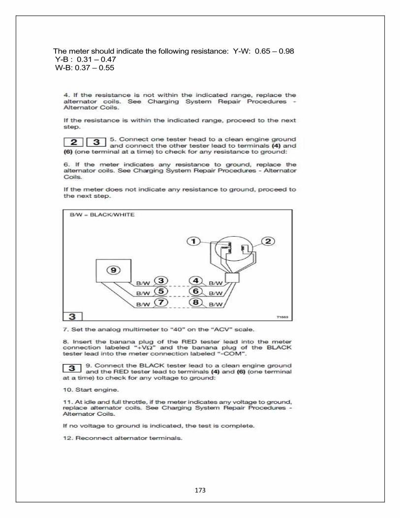
173
The meter should indicate the following resistance: Y-W: 0.65 – 0.98 Y-B : 0.31 – 0.47 W-B: 0.37 – 0.55
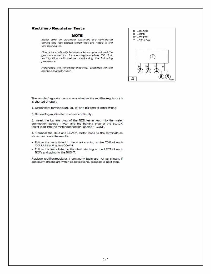
174
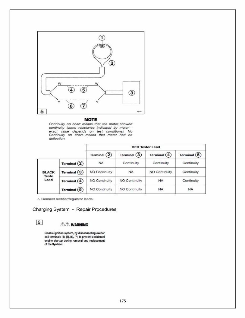
175
Charging System - Repair Procedures
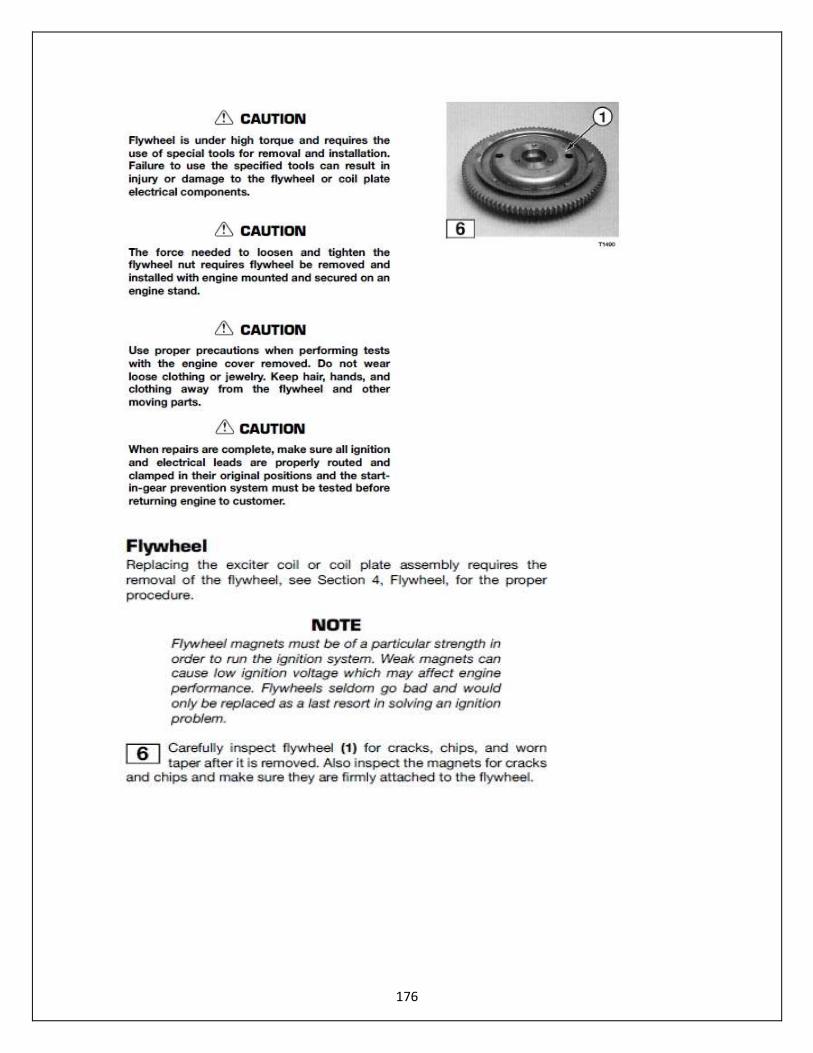
176
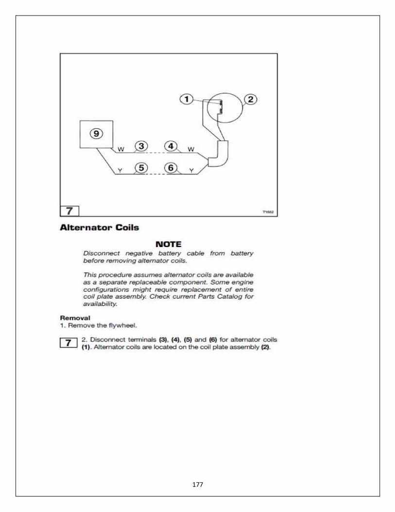
177

178
179
This service manual was developed for the Raider 40 HP Generation II outboard motor. If you have any questions regarding this motor please contact:
Raider Outboards, Inc. 1855 Shepard Drive Titusville, FL 32780
Telephone: (321) 403-3585
www.raideroutboards.com
January 2017