rail alignments for new railways
TRANSCRIPT

Rail Alignments for New Railways
Phil Edwards, Principal Track Engineer, Jacobs
PWI – Ashford Section8th September 2020

• Building a new railway is a major undertaking, and there are many considerations in the feasibility stage before it can be deemed viable.
• Finding a corridor is an early activity to support a business case. Governments and other clients (such as developers) will not embark on a project, incurring significant cost until the business case and social, environmental and economic impacts are studied.
• The rail alignment is only one aspect of any feasibility study, but plays a crucial part as the ‘backbone’ of the scheme from which many other aspects depend.
• Key considerations such as passenger demand, journey times, frequency of rail services and the overall capacity to move passengers and/or freight between geographical centres depends on having a rail alignment and an outline track layout to study.
• Once the initial corridor is established it is often common for a project to be locked into this except for relatively minor adjustments improving the alignment within the corridor width in the following stages before construction.
• Therefore, the initial corridor evaluation and selection is an important task and investing time and money at the start is often a pre curser to a successful project outcome further down the line
Rail Alignments for New Railways: Introduction

• The initial rail corridor study relies on finding an alignment which:
a) satisfies the minimum geometrical requirements,
b) has as few conflicts as possible,
c) serves suitable intermediate and terminal stations and;
d) keeps civil engineering costs to a minimum.
• Finding the most cost effective path through the topography and following existing transport corridors is generally a common starting point.
• In the case of high speed rail, the geometry of existing highways and railways are sometimes difficult to follow due to the flat radius curves necessary for high speed operations.
• Heavy haul freight lines have their own requirements as they are subject to relatively shallow gradients and vertical curve restrictions necessary for the traction of long freight trains with high axle loads.
• Metros and Light Rail projects generally, because of the slower speeds and more relaxed geometry constraints, it’s common to be able to follow highways and roads into city centres to avoid expensive tunnelling and sub surface stations where possible. So, building a rail corridor that is alongside a highway and sometimes between the carriageways, supported in the central reservation is a popular Metro approach in many cities across the world.
Rail Alignments for New Railways: Corridor Study Requirements

• Investment in the latest technology available for finding the lowest cost path through the terrain can potentially save substantial capital costs. So, modelling alignments across a virtual terrain with the capability of overlaying good quality digital mapping is considered to be best practice for initial corridor studies.
• As a Rail Alignment Engineer it is important to have a team with rail alignment experience and capability and get the support from a team of specialist engineers. These would typically include:
Survey, environmental, geotechnical, hydrological, highways, tunnelling, structures and utility engineers.
• Also important is local knowledge so having access to information on land use, politically sensitive areas and any plans for future schemes that may impact on a chosen corridor are key considerations.
• Corridor exploration will lead to an evaluation of options. This is typically carried out as a ‘multi criteria analysis’ which considers the following:
Engineering, capital cost, journey time, operations and maintenance,constructability and environmental factors
Rail Alignments for New Railways: Preparation

• It’s important to consider how the mapping and terrain models can be sourced very early on as this can take time to arrange.
• In the UK there are excellent mapping resources and ground surface models available from Ordnance Survey and local authorities but this is often not the case in other countries.
• To find an initial corridor, the mapping imagery and digital terrain model can be purchased commercially through a satellite survey and imaging supplier.
• For example if a corridor has a chosen study area which is say 25 to 50 Km wide then this will be a vast amount of data and too large for some software applications if it’s too accurate
• At the initial stage its acceptable for the resolution to be a network of survey points say 10 to 20m apart with height data to an accuracy of 0.5m to 1m. This sort of terrain model accuracy will allow a first pass at finding low cost corridors to study further
Rail Alignments for New Railways: Survey and Mapping Resources (1)

• When the initial corridor evaluation has taken place and a corridor is selected it is common to narrow down the study area to say 1 to 5 Km wide.
• The selected corridor requires a more detailed mapping and a digital terrain model with sufficient accuracy to design a rail alignment and calculate ‘cut’ and ‘fill’ volumes.
• Typically a LiDAR (light detection and ranging) survey would be arranged, sourced from a specialist supplier who will carry out dedicated flights using light aircraft, helicopter or drone technology to survey the narrowed corridor.
• The benefit of LiDAR surveys over satellite surveys is the greater accuracy and the ability of the data to be manipulated so that tree cover and vegetation can be stripped out to create a model of the ‘bald’ ground surface.
Rail Alignments for New Railways: Survey and Mapping Resources (2)

• Railway alignment design software applications are used to create alignment strings in model space that are geometrically compliant with the chosen limiting values.
• At the feasibility stage these strings will represent the centre line of the rail alignment from which individual track alignments can be developed at a future stage, when the chosen centre line is relatively fixed.
Rail Alignments for New Railways: Using model applications
• Bentley Open Rail Designer has taken over from Bentley Power Rail Track and Bentley Rail Track. Open Rail Designer is now being used widely for alignment designs. (the image on the right is from Bentley Open Rail)
• 12D is used by some Rail Alignment Designers in Australia

• The ground surface model is supplied as thousands of points with each point having a set of three dimensional values (i.e. a Northing, Easting and height value).
• These points need to be triangulated into a net to represent the ground surface so that when alignment strings cut through the model their height can be determined relative to the net (or ground surface) either above or below the virtual surface.
Rail Alignments for New Railways: Preparing the data

• There are sophisticated modelling applications such as Trimble’s ‘Quantm’ which is able to analyse thousands of alignments and rank them in order of cost to allow options to be short listed.
• Quantm will simultaneously consider environmental, community, cultural, heritage and hydrological impacts in parallel to considering the crossing of linear features, wetlands, floodplains and geology.
Rail Alignments for New Railways: Using Specialist Software Applications
• This is effectively a ‘one stop shop’ where the model is loaded with all the data ‘inputs’ necessary to analyse the cost of each alignment and allows selected alignment ‘output’ strings to be exported and used in other applications.
• The image on the right is from Trimble’s Quantm application

• Assigning colours to particular height bands so that as the elevation increases with the contours of the terrain, the colour gets progressively darker or changes colour the higher the area. This makes contours easy to follow.
• Using a rendered terrain model enables the contour shapes to be easily identified.
Rail Alignments for New Railways: Manual Techniques

• If a project wants to future proof for a higher speed that is in excess of the chosen operational speed, then the radii will need to be flatter and this constrains the alignment further.
• Cant (E) and Cant Deficiency (D) balance i.e. ratio = E/(E+D) x 100%
• For high speed lines the ratio is often 65% to 75% which is a higher ratio than slower speed railways which typically are designed with higher Cant Deficiency values
Rail Alignments for New Railways: Technical parameters – High Speed Lines
• Min curve radii and speeds - minimum radius in high speed sections >350 Km/h is typically between 7,000m and 8,250m depending on what speed is used as the upper limit. Exceptional limits can be lower, but this should be avoided at the feasibility stage.

• The technical parameters for heavy haul freight lines are somewhat different, so there is a balance to be struck if lines are built to be mixed passenger and freight lines.
• In countries that rely on freight traffic being up to 2Km long, using double stack containers with typical maximum axle loads of 32.5 tonnes has to be assessed so that the geometry limits can be set to suit the tractive effort of these very long and heavy trains.
Rail Alignments for New Railways: Technical parameters – Heavy Haul lines
• Typically gradient limits are much flatter than for passenger lines and restrictions are placed on vertical curvature where the longitudinal profile rises and falls within the length of the train
• The technical parameters for light rail are different again and can vary significantly between light rail Metros and Tram systems.
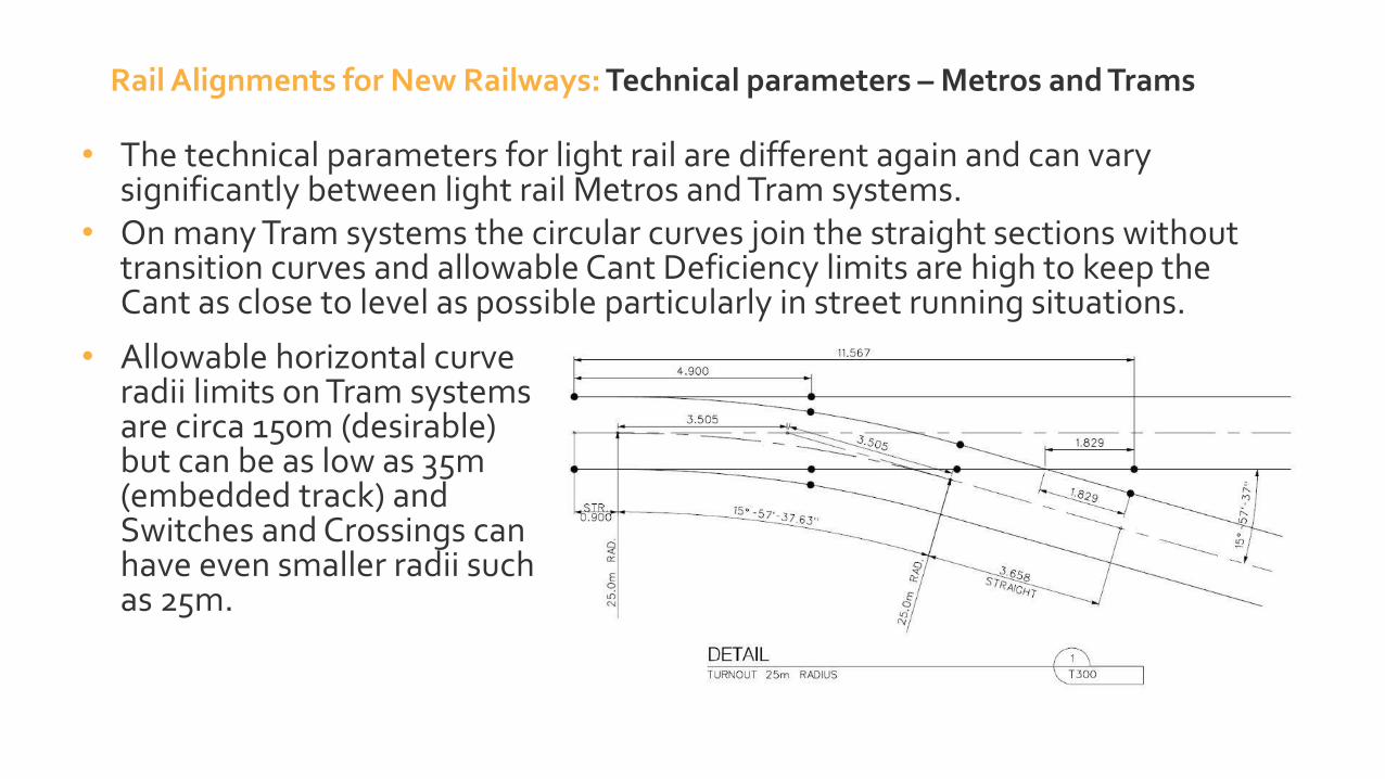
• On many Tram systems the circular curves join the straight sections without transition curves and allowable Cant Deficiency limits are high to keep the Cant as close to level as possible particularly in street running situations.
Rail Alignments for New Railways: Technical parameters – Metros and Trams
• Allowable horizontal curve radii limits on Tram systems are circa 150m (desirable) but can be as low as 35m (embedded track) and Switches and Crossings can have even smaller radii such as 25m.

• Vehicle Gauge to determine track spacings for corridor widths and heights at crossing points
• Overhead catenary systems need to be allowed for, this needs to be considered in the gauging envelope.
• GC Gauge (European) and Standard AAR Gauge (USA) and Composite AAR Gauge (USA Double Stack Containers)
Rail Alignments for New Railways: Technical parameters –Vehicle Gauges

Environmental considerations that would typically be identified on the mapping data in the study area:
• Protected forests and woodlands
• Wildlife Conservation areas• Heritage sites• Sites of Religious interest• City, urban, conurbation and
industrially developed areas
Rail Alignments for New Railways: Environmental Considerations (1)

• Forests and woodlands – Need to plan for the co-existence of the railway and its natural surroundings so that it is managed in future maintenance schedules. ‘Green’ cut and cover tunnels are used to minimise the impacts.
• Wildlife conservation – avoiding the habitat of a protected species and accommodating seasonal migration paths of mammals and reptiles cut off by the new railway unless they are catered for by providing underpasses below the railway.
• In the Middle East it is common to provide Camel crossings where ancient trails are intersected by the line and these underpasses need sufficient headroom for the tallest Camel, so rail elevation is important at these points.
• Heritage sites - Cemeteries and burial grounds fall into this category and are sometimes difficult to identify without site visits and local specialist mapping resources available through local authorities.
• Sites of Religious interest - churches, mosques, synagogues, temples etc. are sensitive to noise and vibration levels from the railway and measures become more expensive the closer the line is built to these receptors.
• Theatres, Hospitals and Laboratories are also where noise and vibration mitigation is required.
• In the city and suburban areas and the urban sprawl of large towns are sometimes impacted in some way.
• A railway passing through a town or village can potentially put a social barrier that changes the dynamic of the area.
• In urban areas, Light Rail systems typically follow the highways and heavy rail and high speed rail often has to tunnel beneath residential areas if the impacts are too great.
Rail Alignments for New Railways: Environmental Considerations (2)

• Geological data
• Geological zones
• Cut and Fill suitability
• Tunnelling avoid zones
• Poor Ground conditions
• Geological mapping information can be viewed in Google Earth and Geospatial Information Systems (GIS applications).
Rail Alignments for New Railways: Geotechnical considerations (1)

• Its good practice to create high level geological zones which group together geological conditions that have similar levels of risk and suitability
Rail Alignments for New Railways: Geotechnical considerations (2)
Zones Geological conditions
Zone 1
(Yellow)
Flat areas of soil/rock with good
bearing capacity with low
environmental sensitivity.
Zone 2
(Green)
Area subject to erosion processes
of medium intensity. Presence of
gully erosion and shallow grooves.
Includes areas of low bearing
capacity.
Zone 3
(Rose)
Escarpments and areas of large
intense erosion and subject to
landslides.
Zone 4
(Blue)
High sensitivity including areas
such as lakes, natural springs, areas
of flooding and erosion caused by
human activity.
• Using the principles of ‘cut’ and ‘fill’ balance requires a geotechnical assessment as material ‘cut’ to form cuttings cannot always be used as ‘fill’ for embankment construction. Using rock blasted from tunnel construction may have explosive material mixed in with the debris, so 100% of the volumes removed cannot always be assumed to be suitable for embankment construction.
• Geology and hydrology conditions are a major area of consideration, as a poor choice of corridor alignment can have serious implications for capital costs and project feasibility as well as on-going maintenance costs when the line is built. Optimising the vertical alignment can help in areas where landslides and flooding are a risk. Selecting a corridor where there are poor ground conditions can result in expensive piling and in some cases such as tunnelling in collapsible soils such as Gypsum should be avoided completely.
• Sometimes poor ground conditions cannot be avoided such as in coastal areas, wetlands and marshes. The rail elevation in these areas is important to be sufficiently high to spread the load to minimise the need for expensive piling depending on the stability of the subgrade below. For example railways are successfully built and maintained on Peat and coastal Sabkha (Middle East) without the need to resort to using piles, but avoiding these areas would be the first consideration.
Rail Alignments for New Railways: Geotechnical considerations (3)

• Many countries have seasonal events resulting in significant surface and ground water flows following periods of heavy rain, particularly in hilly and mountainous areas. These can be in areas that remain dry for much of the year and are not easily identified from mapping and terrain models without the expertise of a Hydrology engineer. Building railways across streams and rivers has to consider worst case water flows, flooding and tidal waters, so modelling the extreme conditions is necessary before rail elevations are fixed.
• Where the rail alignment potentially cuts through water courses these are sometimes not apparent, but at low points in the terrain, piped culverts or box culverts are necessary where the alignment crosses the watercourse. In these areas, a suitable rail elevation is necessary to provide adequate clearances for culverts to be built with sufficient cover between the track system and the top of the culvert.
Rail Alignments for New Railways: Hydrological considerations

• Using highways corridors• Consider reconstructing minor roads to go over or under the railway• Crossing highways and maintaining requirements set by local authorities for clearances
Rail Alignments for New Railways: Highways considerations

• It’s quite common that new alignments will cross or come close to overhead power lines. The Pylon structures are usually easy to identify if the mapping imagery is good quality. Site visits are often necessary to confirm transmission corridors and assess wire heights before they are surveyed. Sometimes it’s beneficial to position the alignment relatively near the Pylon structure maintaining sufficient clearances so that the overhead clearances are maximised. Placing the alignment at mid span between Pylons is likely to result in the wires having to be lifted due to the sag in the wires.
• Where oil pipelines are potential crossing points it is often not possible to divert these without considerable expense. Rail elevations will ideally pass over these and it is not normal to build these into embankments as they need separation from any part of the railway that will cause them to vibrate. So, structures are needed to maintain this separation and horizontal rail alignments are normally adjusted to maintain a sufficient distance from pipelines that run alongside the proposed rail line.
• In some locations high voltage cables are buried and where the rail alignment intersects with these locations it is necessary to provide structures to pass above these utilities. The cables require maintenance access and this includes maintenance vehicles so clearances for maintenance vehicles will affect the soffit height of the bridge and therefore the rail elevation.
Rail Alignments for New Railways: Utilities considerations

• When selecting an alignment both horizontally and vertically it is necessary to understand the relationship between the two.
• There is a maximum height above the terrain beyond which the alignment becomes uneconomic due to the capital costs involved in building high viaducts.
• Therefore, in some cases, horizontal alignments can be driven to taking a very different path in order to satisfy vertical alignment limits. So, it is important to consider the vertical alignment before it is deemed feasible.
• It is very common for alignments to be considered only as a horizontal line on a map in the early feasibility stage.
• In fact, when considering alignments through hills, valleys and mountainous areas, the vertical and the horizontal alignments cannot realistically be considered separately
Rail Alignments for New Railways: Engineering a path through the terrain and into urban areas (1)

• Where the ground surface is generally flat and well away from crossing points, a standard cross section will typically apply with a rail level at 1.0 to 1.2m above the ground level.
• This is the minimum height necessary to ensure that the formation under the track bed can be drained naturally to the surrounding terrain.
• In some locations such as in desert regions, the rail elevation is placed higher to help to mitigate against windblown sand and in other situations such as where there is underlying soft ground with a reasonably stable upper surface, the rail level is elevated to spread the load and avoids disturbing the stable upper surface.
• Where the vertical alignment passes over culverts there are minimum heights required to provide sufficient cover and crossing highways, minor roads, railways, rivers and streams there are minimum clearances and the structural depths of the bridge and the track system to take into account
Rail Alignments for New Railways: Selecting a suitable vertical alignment

• Where the alignment crosses valleys or depressions in the landscape, the railway will be initially on embankment until the height of the embankment reaches a limit as determined by the geotechnical assessment of the earthworks and underlying geology.
Rail Alignments for New Railways: Vertical Alignment: Embankments and Viaducts
• Beyond this, viaducts may be necessary. Viaduct heights above the valley floor should not ideally exceed 30m to 40m although some viaduct examples are anything up to 70m high but these are exceptional structures and very expensive to build, so should be avoided.

• The viaduct length is not critical to the alignment except that any continuous viaduct that exceeds 100m in length must consider the need for rail expansion devices (REDs) in association with the structural expansion joints (SEJs).
• REDs should be located on a section of straight and level track where possible.
Rail Alignments for New Railways: Rail Expansion Devices on Viaducts

• In areas of hills and mountains cuttings are inevitable, and tunnels are necessary where the maximum cutting height is exceeded, or it starts to become uneconomical due to the footprint of cutting area.
• Depending on the geology of the area, the cutting slope angle is determined by the geotechnical engineer and this may result in putting benching (steps) in the cutting face to manage the risk of landslides and rock falls.
• Cuttings deeper than 30m often take up so much corridor width due to the slopes and the benching, that at this point a tunnel becomes more economical. This is particularly the case where two single bore tunnels are assumed, which need to be separated at the portal by say 2½ times the tunnel diameter which has an impact on the adjacent cutting width
Rail Alignments for New Railways: Vertical Alignment: Cutting and Tunnels

• Junction layouts can be arranged in various ways depending operational and maintenance requirements. This affects the footprint required at the junction.
Rail Alignments for New Railways: Horizontal & Vertical Alignment: Junction Layouts

• Main line alignments which run alongside depots and yards should also be restricted to a maximum 0.2% gradient if the depot is connected to the main line at both ends, in order for the depot tracks to also respect a maximum gradient for depots of 0.2%.
• Other alignment constraints can be due to the track layout. Switches and Crossings (S&C) should be located on straight sections of track so junctions, passing loops, station throats, perturbation crossovers and depot access connections need straight sections of alignment with sufficient length to position the S&C away from horizontal transition curves, vertical curves and adjacent S&C units. Other considerations which have an impact on this are the requirements to provide separation between underline structures and S&C.
• All of the aforementioned and any other constraints which relate to the positioning of S&C are based on suitable technical standards, so developing or adopting suitable standards is an early activity in any feasibility study.
Rail Alignments for New Railways: Switches & Crossings and Depot Constraints

• In station platform areas the gradient is typically flat or limited to 0.2% and nominally positioned on a straight horizontal alignment.
Rail Alignments for New Railways: Horizontal & Vertical Alignment: Stations
TYPICAL TWO PLATFORM INTERMEDIATE STATION LAYOUT
TYPICAL FOUR PLATFORM TERMINAL STATION LAYOUT SIMPLE TWO PLATFORM TERMINAL TRAM STOP LAYOUT
TYPICAL SIX PLATFORM TERMINAL STATION LAYOUT (WITH FOUR PLATFORM PERTURBATION LAYOUT)

• In city and suburban areas, intermediate stations may be required where the alignment follows a narrow corridor under a highway.
• The highway corridor may have tall buildings on either side of the road with deep piled foundations.
• In these circumstances a solution can be to stack single tracks (and platforms) one above the other.
Rail Alignments for New Railways: Stations in confined corridors in city areas

• Site visits can provide an important insight into many factors affecting the alignment that may not otherwise be apparent from mapping resources. The timing of the site visits is important as having ‘first pass’ alignment options already developed, can be checked on the ground for feasibility.
• Alignments developed in most software applications can be exported and/or converted into ’.kml’ or ‘.kmz’ files which can be uploaded to Google Maps. This enables anyone to use their phone to locate the alignment on site using the GPS coordinates.
Rail Alignments for New Railways: Site Visits
• The commentary above is based on experiences drawn from a range of studies for High Speed Rail, Heavy Haul, Metros and Tram systems. It is written to give an overview of some factors to be considered when rail alignments for new railways are being developed. It is also draws attention to the differences in standards and requirements between the various traffic types and rail systems, climatic and geological conditions and the local political and environmental complexities.
• If we compare how the railways were designed and built in the Victorian times to now, simplicity has given way to complexity in many areas with the success of the railways and the innovations that have given us one improvement after another. This progress has brought us higher speeds, shorter journey times and more train paths for greater capacity, and we as engineers must play our part in being comfortable with complexity to facilitate that progress.
Rail Alignments for New Railways: Conclusion

‘Life is really simple, but we insist on making it complicated’ – Confucius - circa 482 BC
So, I would agree with Confucius that sometimes it’s better to keep it simple as it’s often true what they say ‘the best ideas are the simple ones’.
Although it’s an engineer’s want to have a thirst for simplicity, for the sake of progress, it’s necessary to drink at the bar of complexity.
VibrationTrack
Noise
CommsEarthworksStructures
Control
Systems
Power
Train
EMC
Rail Alignments for New Railways: Complex Technical Systems & Interfaces
Tunnels
Alignment
Environmental
Track LayoutOperations &
MaintenanceCuttings
Stations
Embankments
Geotechnical
Utilities
Hydrological
Viaducts

Thank You
Rail Alignments for New Railways:
Questions…?