rail platform obstacle detection using labview …805840/fulltext01.pdfshengjie tang rail platform...
TRANSCRIPT
FACULTY OF ENGINEERING AND SUSTAINABLE DEVELOPMENT .
Rail Platform Obstacle Detection Using LabVIEW
Simulation
Shengjie Tang
Jan 2015
Bachelor’s Thesis in Electronics
Bachelor’s Program in Electronics
Examiner: José Chilo
Supervisor: Mahmoud Alizadeh

Shengjie Tang Rail Platform Obstacle Detection Using LabVIEW Simulation
i
Acknowledgement
I would like to thank my supervisor Mahmoud Alizadeh, through his guidance via email during the
period, I was able to finish my thesis work. Even though I encountered lots of setbacks and
frustrations during the period, but I managed and overcame it. I also appreciate the encouragement and
support from my family and my friends. Last but not least, I would like to give myself gratitude that
didn’t give up the work at the time while still having busy schedule.

Shengjie Tang Rail Platform Obstacle Detection Using LabVIEW Simulation
ii

Shengjie Tang Rail Platform Obstacle Detection Using LabVIEW Simulation
iii
Abstract
As the rapid development of the rail transportation industry, rail transportation becomes more popular
as a component of urban public transport systems, but the fallen obstacle(s) from the rail platform
becomes the terrible hidden danger for the rail transportation. As an enclosed public transport systems,
rail transportation creates gathered crowd both on board and on the platform. Although railway is the
safest form of land transportation, it is capable of producing lots of casualties, when there is an
accident.
There are several conventional systems of obstacles detection in platform monitoring systems like
stereo visions, thermal scanning, and vision metric scanning, etc. As the traditional detection systems
could not achieve the demand of detecting the obstacles on the rail within the platform. In this thesis,
the author designs a system within the platform based on laser sensors, virtual instruments technology,
and image processing technology (machine vision) to increase the efficiency of detection system. The
system is useful for guarantying the safety of rail vehicle when coming into the platform and avoid
obstacle(s) on the rail fallen from the platform, having a positive impact on traffic safety to protect
lives of people.
The author used LabVIEW software to create a simulation environment where the input blocks
represent the functionalities of the system, in which simulated train detection and fallen object
detection. In this thesis, the author mainly focuses on fallen object detection. For fallen object
detection, the author used 2D image processing method to detect obstacle(s), so the function is, before
the rail vehicle comes into the platform, the system could detect whether there is fallen obstacle(s) on
the rail within the platform, simultaneously categorize size of the obstacle(s), and then alarm for
delivering the results.
Key words: Rail Platform, Obstacle Detection, LabVIEW Simulation

Shengjie Tang Rail Platform Obstacle Detection Using LabVIEW Simulation
iv

Shengjie Tang Rail Platform Obstacle Detection Using LabVIEW Simulation
v
Table of contents
Acknowledgement .................................................................................................................................... i
Abstract .................................................................................................................................................. iii
Table of contents ..................................................................................................................................... v
1 Introduction ..................................................................................................................................... 1
1.1 Background .............................................................................................................................. 1
1.2 Goal .......................................................................................................................................... 2
1.3 Outline ...................................................................................................................................... 2
2 Theory ............................................................................................................................................. 3
2.1 What is LabVIEW? .................................................................................................................. 3
2.2 Image Processing Technology ................................................................................................. 4
2.3 Virtual Instruments Technology .............................................................................................. 5
2.4 Combination of Image Processing and Virtual Instruments Technology ................................ 6
3 Process and results........................................................................................................................... 8
3.1 Structure of the system ............................................................................................................. 8
3.2 Simulation of the system using LabVIEW ............................................................................. 10
3.2.1 Logic of the system ........................................................................................................ 10
3.2.2 One dimension representation ........................................................................................ 10
3.2.3 Two dimension representation........................................................................................ 17
3.3 Simulation results ................................................................................................................... 19
4 Discussion ..................................................................................................................................... 22
5 Conclusion ..................................................................................................................................... 23
5.1 Future work ............................................................................................................................ 23
References ............................................................................................................................................. 25
Appendix A ........................................................................................................................................... 26

Shengjie Tang Rail Platform Obstacle Detection Using LabVIEW Simulation
vi

Shengjie Tang Rail Platform Obstacle Detection Using LabVIEW Simulation
1
1 Introduction
1.1 Background
As the rapid development of the rail transportation industry, rail transportation becomes utmost
important as a component of urban public transport system [1]. Its advantages of fast, punctual and
large capacity make to become the most frequent choice for urban inhabitants. However, as a high-
density, high flow and relatively enclosed public transportation system, rail transportation brings
gathered crowd when encounters the growing problem of urban traffic congestion. The operational
security issues have become increasingly prominent [2].
Although the rail transportation is the safest approach of public transportation, as an enclosed public
transport systems, rail transportation easily creates gathered crowd both on board and on the platform.
There are also some accidents happened in history. In March 2000, a derailed subway in Japan made
lots of people died. In January 2013, an empty subway in Kunming derailed, but the accident made
one person died and one person injured, the investigation result of the accident shows the obstacles on
the rail lead to the accident.
Figure 1: Scene of Kunming subway derailment accident
According to the statistics, the accident of rail transportation mainly caused by vehicle breakdowns,
track failures, obstacles appear on the rail, human congestion, vandalism, signal systems failures, etc.
Especially, obstacle(s) is a main security risk of rail track, because collision between vehicle and
obstacle(s) could lead to vehicle damage and even vehicle derailed. Above all, it is necessary to set up
the effective obstacle detection system to assure the safety of the rail transportation [2] [3].
Shengjie Tang Rail Platform Obstacle Detection Using LabVIEW Simulation
2
In summary, there is a variety of problems with the existing detection approaches, they are not
applicable to modern rail transport system. So by analyzing the structure and principles of the existing
rail obstacle detection devices, it is particularly necessary to design an effective and low cost of rail
obstacle(s) detection system by using 2D image processing.
1.2 Goal
In this thesis, the goal is to design an obstacle detection system within the rail platform. In order to
achieve the goal, the author will build up the system via LabVIEW, after run through the simulation in
LabVIEW, then deliver the results. The basic functions of the system is to judge if there is obstacle(s)
on rail within the platform or not, and simultaneously categorize size of the obstacle to check if the rail
within the platform is safe enough to allow the rail vehicle enters.
1.3 Outline
In chapter 2, firstly, the author will present the background of LabVIEW software, why is suitable to
use in this project. Secondly, the author will describe the general concept of image processing
technology and its advantages. Thirdly, virtual instruments technology will be introduced, and its
advantages along with the comparison of traditional instruments technology. In the end of this chapter,
advantages of combination of machine vision (image processing technology) and virtual instruments
technology will be presented.
In chapter 3, the process and results will be presented. First, there is explanation for structure of the
system along with the description of functionalities of the system. Second, the set up and simulation of
the system used the software LabVIEW, and proposed methods which are one dimension processing
and two dimension image processing described in details. In the end of this chapter, the results of
simulation using LabVIEW will be delivered.
In the last two chapters, discussion and conclusion will be delivered, the author will discuss the
disadvantages of the traditional rail obstacle detection systems compare to the system which designed
in this project, and then conclude the designed system meets the objective of the project. At last, the
author will propose two improvements as future work for further optimization.

Shengjie Tang Rail Platform Obstacle Detection Using LabVIEW Simulation
3
2 Theory
In the theory part, the author would like to respectively introduce the background of core parts of rail
obstacle detection system in details related to this project, which includes description of LabVIEW,
image processing technology and virtual instruments technology, at last, the author will describe the
advantages of combination of machine vision (image processing technology) and virtual instruments
technology.
2.1 What is LabVIEW?
LabVIEW stands for Laboratory Virtual Instrument Engineering Workbench, which is the innovation
software product by NATIONAL INSTRUMENTS. LabVIEW has become the most widely used,
fastest growing and most powerful integrated graphical software development environment.
LabVIEW is a fast and efficient graphical development environment with simple programming and
particularly suitable for data acquisition and control, data analysis, and data presentation. LabVIEW
has rich graphical interface which allows the users easily produce a variety of graphical interface.
LabVIEW’s programming method is different from the traditional programming methods, which gets
rid of the linear structure problems of traditional language. LabVIEW’s execution order is determined
by the data stream, rather than in the order of appearance of lines of code, so it can design a flow chart
of simultaneous execution of multiple programs. In the human-computer interface design, the users
could select the desired control and data display objects from the control template.
In LabVIEW, virtual instrument consists of the front panel and block-diagram. The front panel
corresponds to the instrument control panel which is a graphical user interface for viewing the main
input and output. The user’s inputs are achieved by the input controls and the completions of the
outputs are achieved by the output indicator. The buttons’ panel, parameter inputs are completed by
the mouse and keyboard.
Operating template is a necessary tool for the formation of the front panel and block diagram.
LabVIEW has a plurality of graphical user templates for creating and running programs. These
templates are freely move around the screen, and be placed anywhere on the screen. There are three

Shengjie Tang Rail Platform Obstacle Detection Using LabVIEW Simulation
4
types of manipulating templates: Tools template, Controls template and Functions template, as shown
in Figure 2 respectively.
Figure 2: LabVIEW Palette
2.2 Image Processing Technology
Image processing system is to convert the analog signals into digital signals through the equipment
such as smart sensors, image sensors, CCD cameras [3], and transfer the digital signals to the image
processing system. The image processing system sets up the tasks based on the detecting requirements
and controls the filed devices according to the results of discrimination. According to the working
environments, the operating systems could be divided into PLC (Programmable Logic Controller)
based systems and PC (Personal Computer) based systems [4][5].
The image processing system connects to the artificial intelligence, graphic processing, neural
networks, pattern recognition and computer graphics, which has its own characters compared with
traditional image analysis system [5], the advantages of the systems is listed as follows:
(1) Generalization
Image processing is performed by the image analysis and processing to obtain the scientific
explanation of the scene, but the system makes decisions after the analysis of images captured by
optical non-contact sensor, and thus controls the machine. So it is more meaningful than traditional
image processing analysis system, it is the extension of image processing analysis system.

Shengjie Tang Rail Platform Obstacle Detection Using LabVIEW Simulation
5
(2) Non-contact
The system uses general non-contact sensors (e.g. CCD cameras, image intensifier, infrared cameras,
etc.) which convert the surrounding scene into electrical signals, and then digitize for further
processing and analysis before drawing conclusions [5].
(3) High-precision, high speed and high reliability.
Using the system instead of humans’ roles in industrial production, it is not only analysis and
processing of images, but also combined the image processing technology with industrial production
closely together. Therefore, compared with the traditional visual processing system, the machine
vision or image processing system emphasizes the accuracy, the speed, the adaptation and industrial
environment reliability [5].
(4) High degree of automation
The system gives the visual function to intelligent robots in order to accomplish many works that
humans unable to complete. It fundamentally determines the system can achieve high degree of
automation efficiently. Hence, save resources [5].
2.3 Virtual Instruments Technology
Virtual Instruments Technology is the combination of software and hardware platform, in which takes
the general personal computer (PC) as core of the system and together with the corresponding
hardware for testing functions as the input/output interface. It virtualizes the instrument’s panel and
functions on the computer screen using the software development platform, and then controlled by the
mouse and keyboard [6]. Compare to virtual instruments technology, machine vision system or image
processing technology mainly focus on hardware platform.
Together with one or several general data acquisition cards, infrared sensors, image sensors, etc, the
users could build kinds of instruments with any functions such as voltmeters, oscilloscopes, spectrum
analyzers, etc. The appearance of the virtual instruments blurs the boundary between measuring
instruments and computers. Virtual instrument technology is the in-depth product of the combination
of modern computer technology and instrumentation technology, it is an important technology in
today's computer-aided test (CAT) field. Virtual instruments technology is the effective combination
of instruments and measurements, hardware resources from control system and software resources
generated by virtual instruments [6].

Shengjie Tang Rail Platform Obstacle Detection Using LabVIEW Simulation
6
Table 1: Comparison of virtual instruments and traditional instruments
Virtual Instruments Traditional Instruments
Customize functions Functions provide by manufacturers
Low cost of development and maintenance High cost of development and maintenance
Short developing cycle Long developing cycle
The software is the key The hardware is the key
More display choices Limited display choices
Automatic measurement Conventional measurement
2.4 Combination of Image Processing and Virtual Instruments
Technology
The traditional machine vision technology, which based on dedicated hardware is not suitable for
development nowadays. It has expensive hardwares which have difficulties for development, so its
cycle and cost of development is extra high. Using the virtual instrument with powerful development
tools with image processing technology, it greatly reduces the development cycle and cost in the
meantime increases the reusability of the program [6][7].
The standard image processing system based on virtual instruments has shown in Figure 3.
Figure 3: Image processing system based on virtual instruments technology
(1) CCD Camera.
The CCD Camera is the imaging device. If there are cameras, the data will be captured by Image
Acquisition Card. The output data is standard single color video (RS-170/CCIR) or RGB (Red, Green,
Blue) signal [6].

Shengjie Tang Rail Platform Obstacle Detection Using LabVIEW Simulation
7
(2) Light
As the aided imaging device, the light plays a key role in the quality of the frame. There are plenty of
different kinds of lights such as LED (Light Emitting Diode) lights with different shapes, high
frequency fluorescent lamps, etc [6].
(3) Image Acquisition Card
The main function of the Image Acquisition Card is transferring the camera data into PC. It transforms
the analog or digital signal to image data flow as a certain format. Meanwhile, it controls specific
parameters of the camera such as trigger signal and shutter speed [6].
(4) PC Platform
PC is core of the system, most of the image data and control commands are processed here. Because
sometimes there are disturbances on the platform, so the industrial PC is better for the system [6].
(5) Image Processing Software
The Image Processing Software is to process the image data and output the result, so LabVIEW is
needed here.
Above all, these are the basic parts of the image processing detection system based on virtual
instruments technology. Compare to the traditional railway platform fallen object detection systems
which are using stereo cameras, thermal cameras, etc, but in this project, the system is using CCD
cameras instead. The advantages of CCD cameras are, way more sensitive to light so it decrease the
needed exposure time to capture faint images, the cameras have greater dynamic range, so they can
capture the detail of brightness and blur/faint easier in a single exposure, the cameras can take wide
angle shots, and chips of cameras can produce images with fewer pixel defects. In this case, it is better
than using stereo cameras, thermal cameras, etc. In addition, the real application requires other aided
controlling modules.
Shengjie Tang Rail Platform Obstacle Detection Using LabVIEW Simulation
8
3 Process and results
This chapter is mainly analyzing the functionalities of the Rail Platform Obstacle Detection System,
building the structure of system in LabVIEW and showing the simulation results. The author proposed
two methods for obstacle(s) detection, the first method is simple and one-dimension (1D) processing
(sinewave), and the second method is a more complex and two-dimension image processing (2D
image).
3.1 Structure of the system
Before the rail vehicle comes into the platform, through the image of rail which is taken by CCD
camera, the Rail Platform Obstacle Detection System uses image processing technology to analyze
whether there is obstacle(s) on the rail, and then decide size of the obstacle(s).
According to the functions of the Rail Platform Obstacle Detection System, it is divided into three
parts:
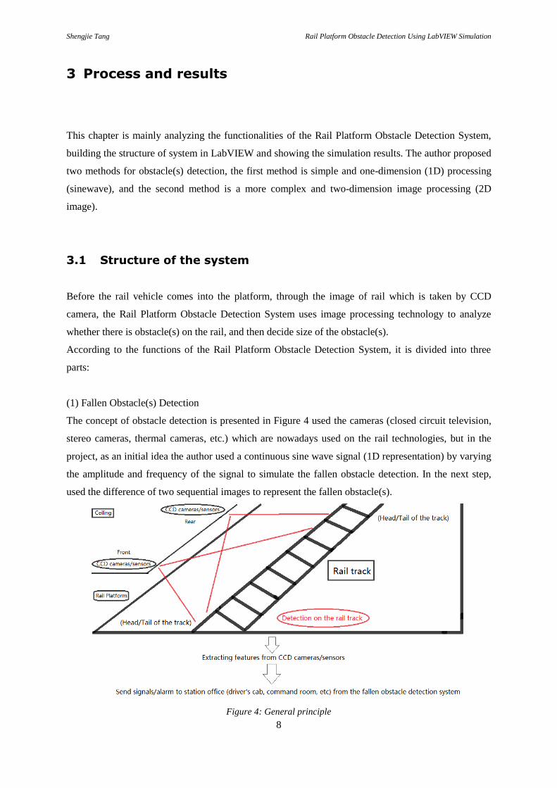
(1) Fallen Obstacle(s) Detection
The concept of obstacle detection is presented in Figure 4 used the cameras (closed circuit television,
stereo cameras, thermal cameras, etc.) which are nowadays used on the rail technologies, but in the
project, as an initial idea the author used a continuous sine wave signal (1D representation) by varying
the amplitude and frequency of the signal to simulate the fallen obstacle detection. In the next step,
used the difference of two sequential images to represent the fallen obstacle(s).
Figure 4: General principle
Shengjie Tang Rail Platform Obstacle Detection Using LabVIEW Simulation
9
(2) Train Enter/Leave Detection
The 3 laser sensors are placed at the start and end of the platform area whose functionality is to give
the status of train entering and leaving the platform. These will be inputs signal generators whose
status can be changed virtually in the software. But train detection is only the side function of the
system, in this thesis, the author mainly focuses on fallen obstacle detection.
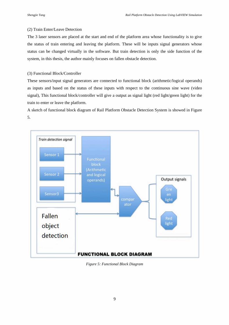
(3) Functional Block/Controller
These sensors/input signal generators are connected to functional block (arithmetic/logical operands)
as inputs and based on the status of these inputs with respect to the continuous sine wave (video
signal), This functional block/controller will give a output as signal light (red light/green light) for the
train to enter or leave the platform.
A sketch of functional block diagram of Rail Platform Obstacle Detection System is showed in Figure
5.
Figure 5: Functional Block Diagram
Shengjie Tang Rail Platform Obstacle Detection Using LabVIEW Simulation
10
3.2 Simulation of the system using LabVIEW
3.2.1 Logic of the system
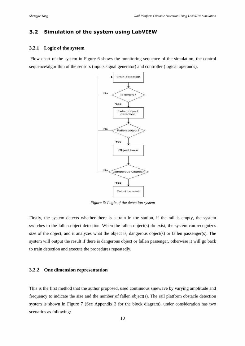
Flow chart of the system in Figure 6 shows the monitoring sequence of the simulation, the control
sequence/algorithm of the sensors (inputs signal generator) and controller (logical operands).
Figure 6: Logic of the detection system
Firstly, the system detects whether there is a train in the station, if the rail is empty, the system
switches to the fallen object detection. When the fallen object(s) do exist, the system can recognizes
size of the object, and it analyzes what the object is, dangerous object(s) or fallen passenger(s). The
system will output the result if there is dangerous object or fallen passenger, otherwise it will go back
to train detection and execute the procedures repeatedly.
3.2.2 One dimension representation
This is the first method that the author proposed, used continuous sinewave by varying amplitude and
frequency to indicate the size and the number of fallen object(s). The rail platform obstacle detection
system is shown in Figure 7 (See Appendix 3 for the block diagram), under consideration has two
scenarios as following:

Shengjie Tang Rail Platform Obstacle Detection Using LabVIEW Simulation
11
Train Detection Systems (Side function)
Fallen Object Detection Systems (Main function)
The above two scenarios are described below in a functional and step by step manner to understand
the basic functionalities of the simulation program.
Figure 7: Interface of the rail platform obstacle detection system
Generally, a train at the station has four different states as following:
A. Approach (IN State)
B. Halt (ON-State)
C. Leave (OUT-State)
D. Exit (OFF-State).

Shengjie Tang Rail Platform Obstacle Detection Using LabVIEW Simulation
12
The AMBER LIGHT is activated as initial condition shown in Figure 8.
Figure 8: Initial Condition
Scenario 1 – Train Detection
When the train approaches the platform, the APPROACH sensor gets activated, and gives the signal to
activate the camera for fallen obstacle detection, if the rail is clear, then the system will switched to
GREEN light allow the train to enter, as shown in Figure 9.
Figure 9: Train Detection
Shengjie Tang Rail Platform Obstacle Detection Using LabVIEW Simulation
13
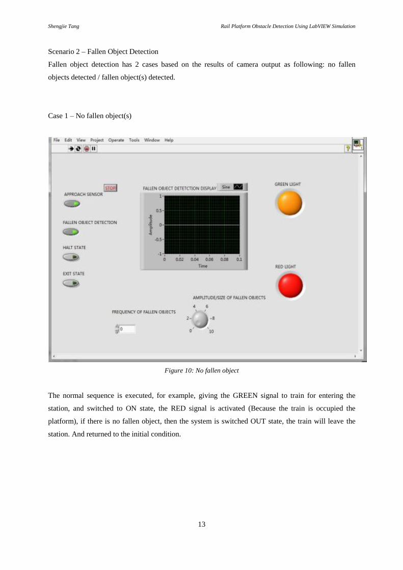
Scenario 2 – Fallen Object Detection
Fallen object detection has 2 cases based on the results of camera output as following: no fallen
objects detected / fallen object(s) detected.
Case 1 – No fallen object(s)
Figure 10: No fallen object
The normal sequence is executed, for example, giving the GREEN signal to train for entering the
station, and switched to ON state, the RED signal is activated (Because the train is occupied the
platform), if there is no fallen object, then the system is switched OUT state, the train will leave the
station. And returned to the initial condition.

Shengjie Tang Rail Platform Obstacle Detection Using LabVIEW Simulation
14
Case 2 – Fallen object detection
Figure 11: Fallen object detection (a small object)
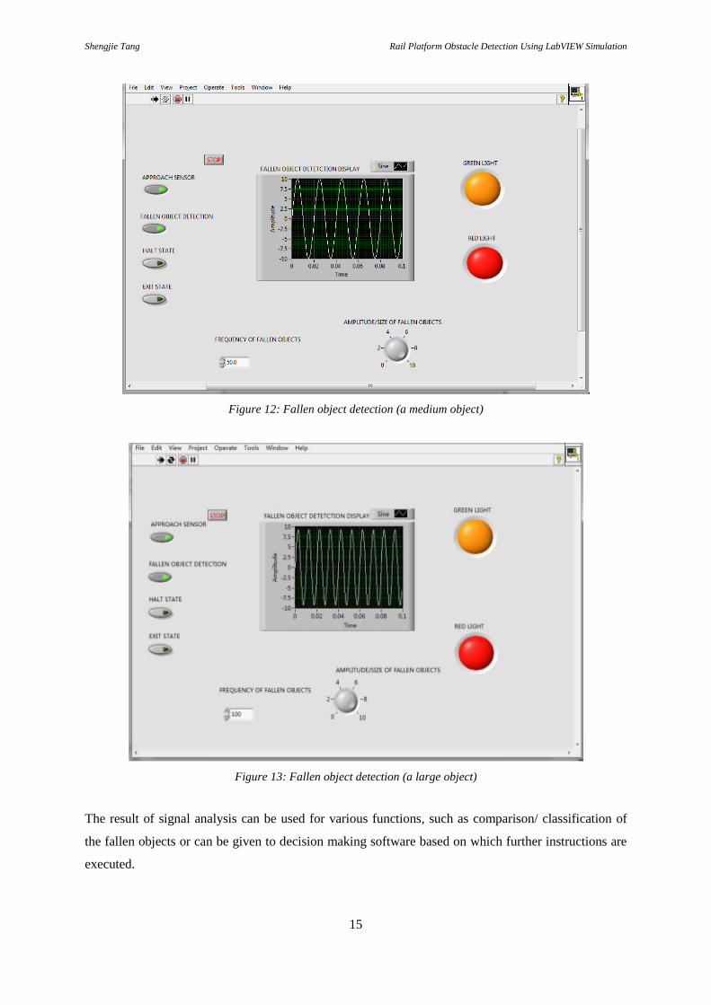
When there is fallen object(s) detected, then the video signal is analyzed by running the amplitude and
frequency scan. The combination of different frequencies and same amplitudes can categorize the
fallen obstacle into small, medium, large size, as shown in Figure 11, Figure 12, and Figure 13
respectively.
Shengjie Tang Rail Platform Obstacle Detection Using LabVIEW Simulation
15
Figure 12: Fallen object detection (a medium object)
Figure 13: Fallen object detection (a large object)
The result of signal analysis can be used for various functions, such as comparison/ classification of
the fallen objects or can be given to decision making software based on which further instructions are
executed.
Shengjie Tang Rail Platform Obstacle Detection Using LabVIEW Simulation
16
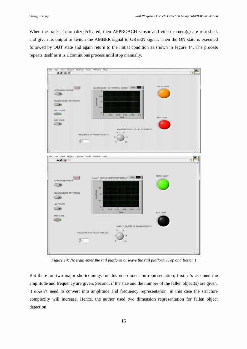
When the track is normalized/cleared, then APPROACH sensor and video camera(s) are refreshed,
and given its output to switch the AMBER signal to GREEN signal. Then the ON state is executed
followed by OUT state and again return to the initial condition as shown in Figure 14. The process
repeats itself as it is a continuous process until stop manually.
Figure 14: No train enter the rail platform or leave the rail platform (Top and Bottom)
But there are two major shortcomings for this one dimension representation, first, it’s assumed the
amplitude and frequency are given. Second, if the size and the number of the fallen object(s) are given,
it doesn’t need to convert into amplitude and frequency representation, in this case the structure
complexity will increase. Hence, the author used two dimension representation for fallen object
detection.

Shengjie Tang Rail Platform Obstacle Detection Using LabVIEW Simulation
17
3.2.3 Two dimension representation
The system used the camera to acquire the video signal, able to capture the sequential frame of rail to
simulate process of obstacle detection. The principle of the obstacle detection process is to find the
difference of two frames. In the system, users can also define the threshold (size) of small and medium
object(s), the purpose for doing this is enable to let the system categorize the size of different object(s)
quickly and display in Falling Object Evaluation section. The simulation results will be shown in
section 3.3. The system is shown in Figure 15.
Figure 15: Interface of image processing
Figure 16: Core function of image processing displayed in block diagram
The core function of image processing for finding difference of two frames is using a functional block called
RGB match, as shown in Figure 16. Frames/pictures are consist of pixels, each frame has specific pixels, each

Shengjie Tang Rail Platform Obstacle Detection Using LabVIEW Simulation
18
pixel consists of red, green, blue components (RGB) respectively, and the total pixels of one frame is equal to
vertical pixels of the frame multiply by horizontal pixels of the frame (e.g. 323×420 = 135660 pixels).
In the function of RGB match (See Appendix.2), the system resolves pixels of the frames into red, green, blue
components, if there is an object on the rail, the value of RGB components of modified frame will be different
than the value of original frame, and the function calculates the difference of the value in the meantime outputs
the result in the difference section as shown in Figure 15.
The model for finding difference of two sequential images is:
𝐼𝑑(𝑥, 𝑦) = |𝐼1(𝑥, 𝑦) − 𝐼2(𝑥, 𝑦)| (1)
where
𝐼1 and 𝐼2 represent the first and the second images, respectively, with the size M × N.
x and y are the positions of the pixels on the images, 1≤ x≤ M, 1≤ y≤ N.
𝐼𝑑 is the absolute image of the difference of 𝐼1 and 𝐼2.
The objects classification based on size is given in Table 2 as following:
Table 2: The objects classification based on size
Number of pixels Object descriptions Objects classification.
≤ 3000 Plastics, papers, cups, cigarettes, straps, etc. Small
(3000,7000] Concrete steel, glass flasks, etc. Medium
> 7000 Fallen passengers, wooden cartoons, etc. Large
Using two dimension representation also called 2D image processing method, the fallen obstacle detection
system is built within the rail platform, so the velocity of the rail vehicle is not considered, because the rail
vehicle cannot enter the platform until the system makes sure the rail is clear. The system or the cameras
specifically should be mounted on the ceiling of the platform, at least two cameras, one should be placed near
head of the rail, and the second one should be mounted near tail of the rail, so in this case, the cameras can cover
full range of the rail within the platform. The threshold of pixels is hypothetical value, equal and smaller than
3000 pixels can classify as small object, in between 3000 and 7000 pixels can classify as medium object, larger
than 7000 pixels can classify as large object. Since the system can define the threshold of small and medium
object, so the operators of train station can define their own threshold of the obstacles, they can import the data
from statistical analysis of fallen obstacles on the rail.
Shengjie Tang Rail Platform Obstacle Detection Using LabVIEW Simulation
19
3.3 Simulation results
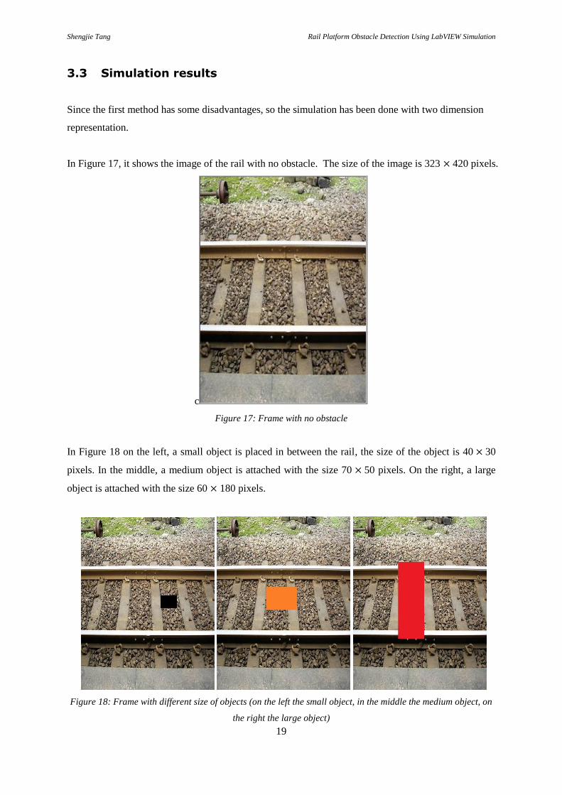
Since the first method has some disadvantages, so the simulation has been done with two dimension
representation.
In Figure 17, it shows the image of the rail with no obstacle. The size of the image is 323 × 420 pixels.
c
Figure 17: Frame with no obstacle
In Figure 18 on the left, a small object is placed in between the rail, the size of the object is 40 × 30
pixels. In the middle, a medium object is attached with the size 70 × 50 pixels. On the right, a large
object is attached with the size 60 × 180 pixels.
Figure 18: Frame with different size of objects (on the left the small object, in the middle the medium object, on
the right the large object)

Shengjie Tang Rail Platform Obstacle Detection Using LabVIEW Simulation
20
The results of the simulation for the object explained in Figure 18 are shown in Figure 19. The
classification of the objects is done by thresholds defined in Table 2.
Figure 19: Falling object evaluation
The output of the detection block is shown in Figure 20. The detected fallen object is the difference of
two images (with and without obstacles) which is calculated from equation (1).
Figure 20: The detected objects with different sizes
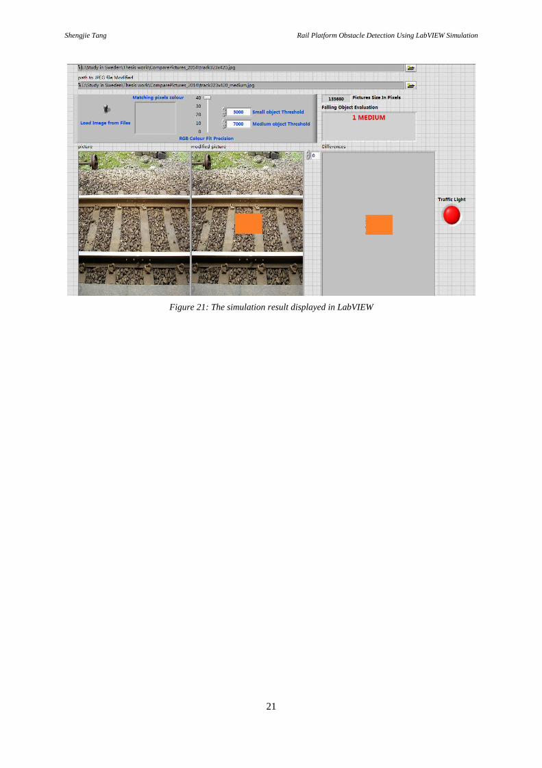
The outcome of the processing block is shown in the Figure 21. The system distinguishes the sizes of
obstacles on the rail, divides them into SMALL, MEDIUM and LARGE level, and delivers the results.
When the detected obstacle(s) is medium or large size, the traffic light switches to red, which means
there is obstacle(s) on the rail threatening the safety of rail vehicle, therefore the rail vehicle could not
enter the platform.
Shengjie Tang Rail Platform Obstacle Detection Using LabVIEW Simulation
21
Figure 21: The simulation result displayed in LabVIEW

Shengjie Tang Rail Platform Obstacle Detection Using LabVIEW Simulation
22
4 Discussion
The traditional rail obstacle detection systems are commonly installed infrared sensors or other
sensing devices to detect whether there is obstacle(s) on the rail. But the devices/equipment are
expensive, having unstable detection effect, small coverage and other shortcomings. So the Rail
Obstacles Detection System described above is based on machine vision (image processing
technology), which achieves a low-cost, monitoring coverage, stable detection results. Therefore, the
system may provide a possibility to perform in the next generation automated rail transportation.
However, in this system, a simple method was used to detect the obstacle between two sequential
images, and using an advanced method can improve the performance of the detection block in the
presence of complicated obstacles.

Shengjie Tang Rail Platform Obstacle Detection Using LabVIEW Simulation
23
5 Conclusion
As the rapid development of rail transportation industry, the safety of the rail vehicle operation is
becoming the focus of attention for most of the people increasingly. As the traditional detection
methods could not achieve the demand of detecting obstacle(s) on the rail within the platform, in this
paper, the author designs a system which uses CCD camera and image processing technology to detect
obstacle(s) on the rail within the platform to increase the efficiency. The basic principle of the system
is, before the rail vehicle comes into the platform, the system could detect whether there is fallen
obstacle(s) on the rail of platform or not, categorize size of the obstacle(s), and then alarm. The system
is to guarantee the safety of rail vehicle when coming into the platform and avoid the obstacle(s) on
the rail fallen from the platform, to assure the traffic safety, to protect lives of people.
Through the simulation of LabVIEW, used the 2D image processing approach shows that the Rail
Platform Obstacle Detection System meets the designing requirements for detecting the obstacles and
evaluating their sizes on the rail.
5.1 Future work
In order to improve the thesis work, the author would like to propose two improvements as future
work.
1. Detection of rail obstacle(s)
The Rail Platform Obstacle Detection System is presented in previous chapters used the frames of rail
which added some blocks with different colors and sizes to simulate the fallen obstacles on the rail.
Although the blocks reflect the characters of obstacles to certain extent, the rail obstacles have some
confounding factors such as gradient colors, irregular shapes and partial shade, etc. So it requires
deeper exploration to analyze the detecting higher efficiency of the Rail Platform Obstacle Detection
System.
2. Detection in weak light condition
The Rail Platform Obstacle Detection System should be effective in all kinds of environments. The
simulation in this paper uses the image which is captured in bright light condition, but when in the bad
weather condition or the ambient light condition is weak, so contrast of the image is affected, and the
performance of the system may decrease. Hence, it needs further optimization for setting up the
system.

Shengjie Tang Rail Platform Obstacle Detection Using LabVIEW Simulation
24
Shengjie Tang Rail Platform Obstacle Detection Using LabVIEW Simulation
25
References
[1] J.H. Kim, S.H Lee and J.Ha. Kim, “Detection of a drivable environment for UGV using multiple
laser sensors,” International Conference on Control, Automation and Systems, pp. 590-594, 2008.
[2] F. Maire, “Vision based anti-collision system for rail track maintenance vehicles,” Advanced Video
and Signal Based Surveillance, IEEE, pp. 170-175, 2007.
[3] H.C. Moon, J.H. Kim and J.Ha. Kim, “Obstacle detecting system for unmanned ground vehicle
using laser scanner and vision,” International Conference on Control, Automation and Systems, pp.
1758-1761, 2007.
[4] S. Wender and K. Dietmayer, “3D vehicle detection using a laser scanner and a video camera,”
Intelligent Transport Systems, IET, vol. 2, pp. 105-112, 2008.
[5] H.J Zhao, Y.Z. Chen and R. Shibasaki, “An efficient extrinsic calibration of a multiple laser
scanners and cameras' sensor system on a mobile platform,” in Intelligent Vehicles Symposium,
IEEE, pp. 422-427, 2007.
[6] J. Roberts and P. Corke, “Obstacle Detection for a Mining Vehicle using a 2D Laser,” Australian
Conference of the Mining Device, vol.5, pp. 104-109, 2000
[7] S.C. Oh, S.H. Park and Chang-Mu Lee, “Railway platform monitoring system using stereo vision
algorithm for passenger's safety,” in Telecommunications Energy Conference, 2009. INTELEC,
31st International, pp. 1-4, 2009.
Shengjie Tang Rail Platform Obstacle Detection Using LabVIEW Simulation
26
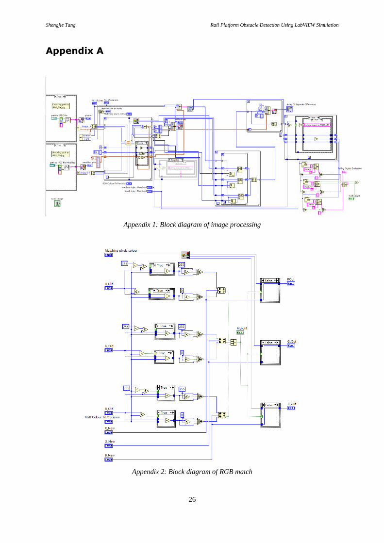
Appendix A
Appendix 1: Block diagram of image processing
Appendix 2: Block diagram of RGB match

Shengjie Tang Rail Platform Obstacle Detection Using LabVIEW Simulation
27
Appendix 3: Block diagram of train detection system

Shengjie Tang Rail Platform Obstacle Detection Using LabVIEW Simulation
C1