railing - adobe · transcend railing trex transcend railing parts ... » trex transcend railings...
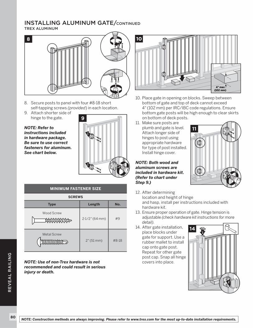
TRANSCRIPT
37
RA
ILIN
G
37
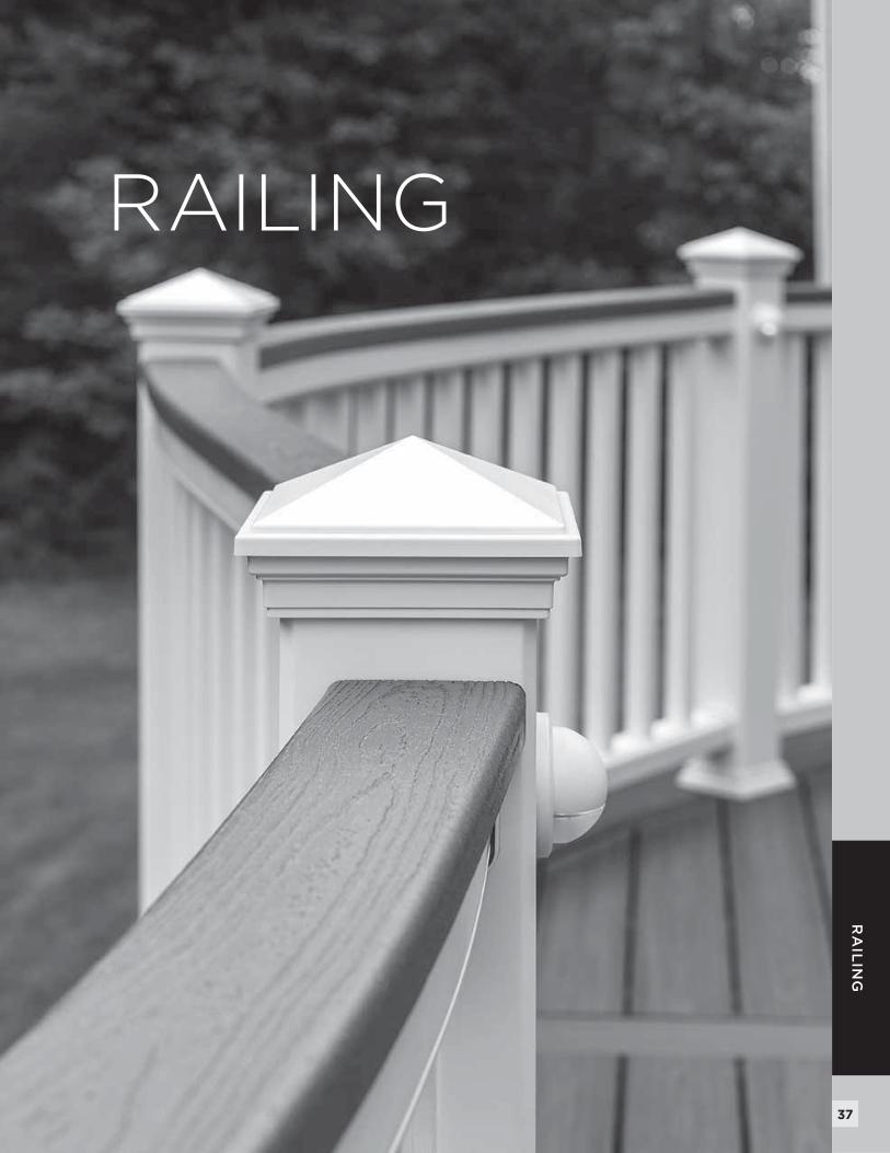
RAILING
38
TR
AN
SC
EN
D R
AIL
ING
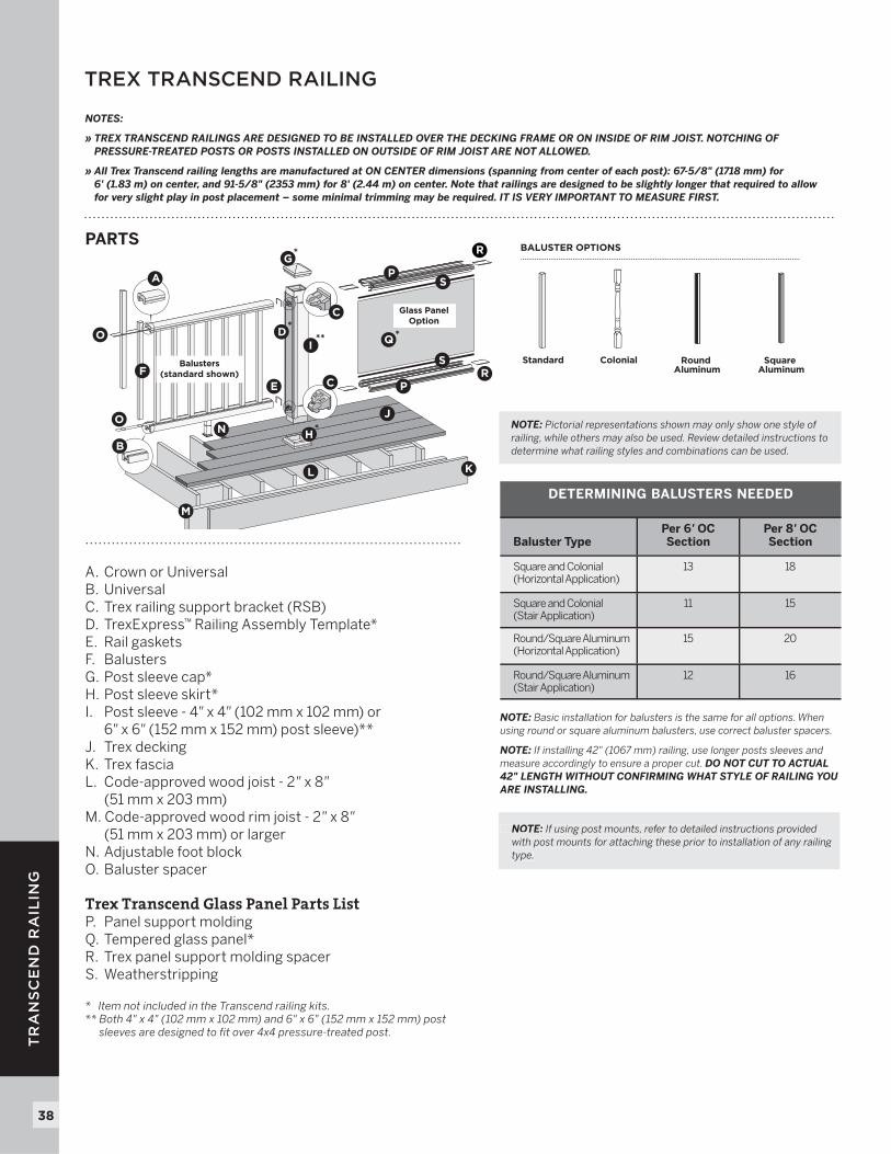
TREX TRANSCEND RAILING
PARTS
A. Crown or UniversalB. UniversalC. Trex railing support bracket (RSB)D. TrexExpress™ Railing Assembly Template*E. Rail gasketsF. BalustersG. Post sleeve cap*H. Post sleeve skirt*I. Post sleeve - 4" x 4" (102 mm x 102 mm) or 6" x 6" (152 mm x 152 mm) post sleeve)**J. Trex decking K. Trex fasciaL. Code-approved wood joist - 2" x 8" (51 mm x 203 mm)M. Code-approved wood rim joist - 2" x 8" (51 mm x 203 mm) or largerN. Adjustable foot blockO. Baluster spacer
Trex Transcend Glass Panel Parts ListP. Panel support moldingQ. Tempered glass panel*R. Trex panel support molding spacerS. Weatherstripping
* Item not included in the Transcend railing kits.** Both 4" x 4" (102 mm x 102 mm) and 6" x 6" (152 mm x 152 mm) post
sleeves are designed to fit over 4x4 pressure-treated post.
*
A
B
C
C
D*
EF
G*
H*
I**
J
KL
M
NO
O
P
P
Q
R
R
S
SBalusters(standard shown)
Glass PanelOption
Standard Colonial Round Aluminum
Square Aluminum
BALUSTER OPTIONS
NOTE: Basic installation for balusters is the same for all options. When using round or square aluminum balusters, use correct baluster spacers.
NOTE: If installing 42" (1067 mm) railing, use longer posts sleeves and measure accordingly to ensure a proper cut. DO NOT CUT TO ACTUAL 42" LENGTH WITHOUT CONFIRMING WHAT STYLE OF RAILING YOU ARE INSTALLING.
NOTE: If using post mounts, refer to detailed instructions providedwith post mounts for attaching these prior to installation of any railing type.
NOTE: Pictorial representations shown may only show one style of railing, while others may also be used. Review detailed instructions to determine what railing styles and combinations can be used.
NOTES:
» TREX TRANSCEND RAILINGS ARE DESIGNED TO BE INSTALLED OVER THE DECKING FRAME OR ON INSIDE OF RIM JOIST. NOTCHING OF PRESSURE-TREATED POSTS OR POSTS INSTALLED ON OUTSIDE OF RIM JOIST ARE NOT ALLOWED.
» All Trex Transcend railing lengths are manufactured at ON CENTER dimensions (spanning from center of each post): 67-5/8" (1718 mm) for 6' (1.83 m) on center, and 91-5/8" (2353 mm) for 8' (2.44 m) on center. Note that railings are designed to be slightly longer that required to allow for very slight play in post placement – some minimal trimming may be required. IT IS VERY IMPORTANT TO MEASURE FIRST.
DETERMINING BALUSTERS NEEDED
Baluster TypePer 6' OCSection
Per 8' OCSection
Square and Colonial(Horizontal Application)
13 18
Square and Colonial(Stair Application)
11 15
Round/Square Aluminum(Horizontal Application)
15 20
Round/Square Aluminum(Stair Application)
12 16
NOTE: If using post mounts, refer to detailed instructions providedwith post mounts for attaching these prior to installation of any railing type.
39
TR
AN
SC
EN
D R
AIL
ING
39NOTE: Construction methods are always improving. Please refer to www.trex.com for the most up-to-date installation requirements.
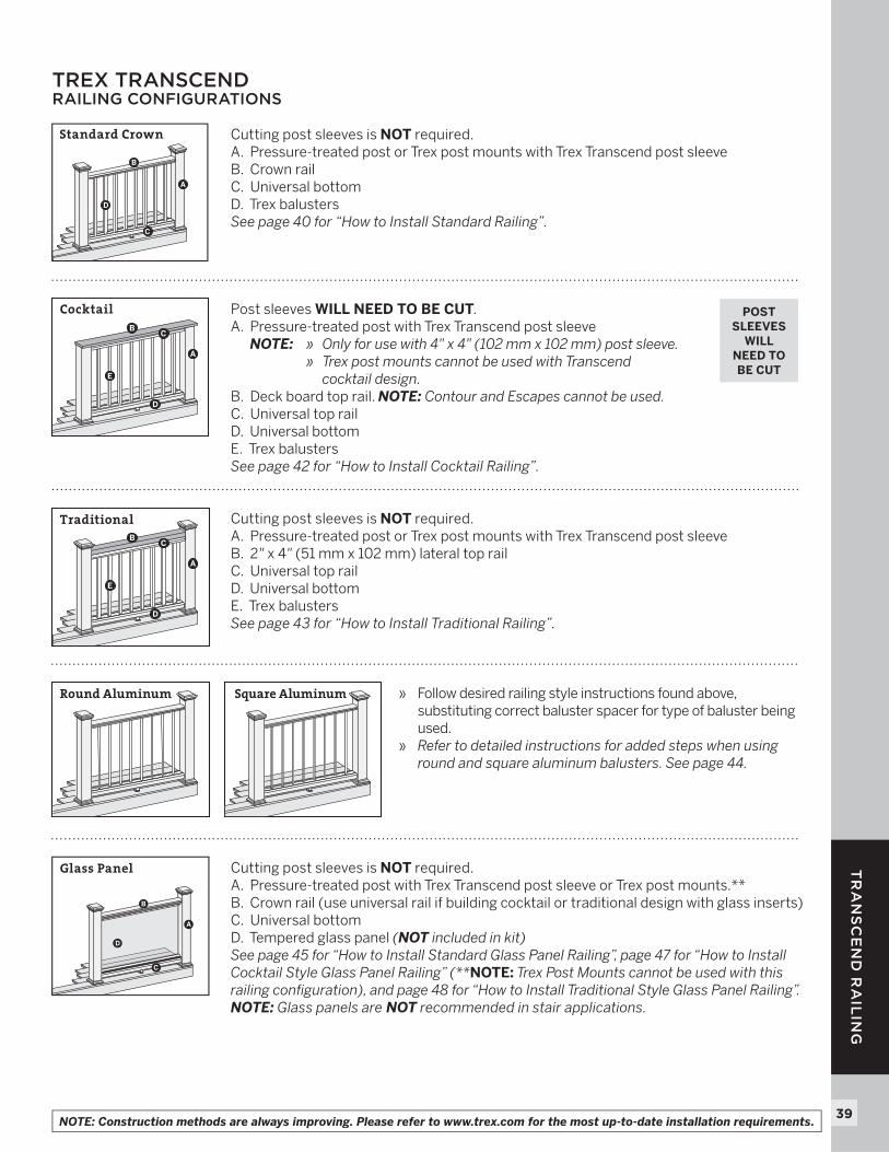
TREX TRANSCEND RAILING CONFIGURATIONS
Cutting post sleeves is NOT required. A. Pressure-treated post or Trex post mounts with Trex Transcend post sleeveB. Crown railC. Universal bottomD. Trex balusters See page 40 for “How to Install Standard Railing”.
Cutting post sleeves is NOT required. A. Pressure-treated post or Trex post mounts with Trex Transcend post sleeveB. 2" x 4" (51 mm x 102 mm) lateral top railC. Universal top railD. Universal bottomE. Trex balusters See page 43 for “How to Install Traditional Railing”.
» Follow desired railing style instructions found above, substituting correct baluster spacer for type of baluster being used.
» Refer to detailed instructions for added steps when using round and square aluminum balusters. See page 44.
Post sleeves WILL NEED TO BE CUT. A. Pressure-treated post with Trex Transcend post sleeve
NOTE: » Only for use with 4" x 4" (102 mm x 102 mm) post sleeve. » Trex post mounts cannot be used with Transcend
cocktail design. B. Deck board top rail. NOTE: Contour and Escapes cannot be used.C. Universal top railD. Universal bottomE. Trex balusters See page 42 for “How to Install Cocktail Railing”.
A
B
C
D
A
B
D
C
E
A
B
D
C
E
A
B
C
D
Cutting post sleeves is NOT required. A. Pressure-treated post with Trex Transcend post sleeve or Trex post mounts.**B. Crown rail (use universal rail if building cocktail or traditional design with glass inserts)C. Universal bottomD. Tempered glass panel (NOT included in kit) See page 45 for “How to Install Standard Glass Panel Railing”, page 47 for “How to Install Cocktail Style Glass Panel Railing” (**NOTE: Trex Post Mounts cannot be used with this railing confi guration), and page 48 for “How to Install Traditional Style Glass Panel Railing”. NOTE: Glass panels are NOT recommended in stair applications.
POST SLEEVES
WILL NEED TO BE CUT
Round Aluminum
Glass Panel
Standard Crown
Cocktail
Traditional
Square Aluminum
40
TR
AN
SC
EN
D R
AIL
ING
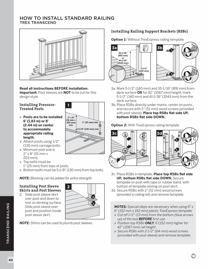
HOW TO INSTALL STANDARD RAILINGTREX TRANSCEND
Read all instructions BEFORE installation.Important: Post sleeves are NOT to be cut for this design style.
Installing Pressure-Treated Posts
» Posts are to be installed 6' (1.83 m) or 8' (2.44 m) on center to accommodate appropriate railing length.
» Attach posts using 1/2" (130 mm) carriage bolts.
» Minimum joist size is2" x 8" (51 mm x203 mm).
» Top bolts must be 1" (25 mm) from tops of joists.
» Bottom bolts must be 5-1/8 " (130 mm) from top bolts.
NOTE: Blocking can be added for extra strength. Installing Post Sleeve Skirts and Post Sleeves 2. Slide post sleeve skirt
over post and down to rest on decking surface. Slide post sleeve over post and position inside post sleeve skirt.
NOTE: Shims can be used to plumb post sleeves.
Installing Railing Support Brackets (RSBs)
Option 1: Without TrexExpress railing template
3a. Mark 5-1/2" (140 mm) and 35-1/16" (891 mm) from deck surface OR for 42" (1067 mm) height, mark 5-1/2 " (140 mm) and 41-1/16 " (1043 mm) from the deck surface.3b. Place RSBs directly under marks, center on posts, and secure with 2" (51 mm) wood screws (provided with post sleeve). Place top RSBs fl at side UP, bottom RSBs fl at side DOWN.
Option 2: With TrexExpress railing template
3c. Place RSBs in template. Place top RSBs fl at side UP, bottom RSBs fl at side DOWN. Secure template on post with tape or rubber band, with bottom of template resting on post skirt.3d. Secure RSBs with 2 " (51 mm) wood screws (provided in railing kit) and remove template.
NOTES: Special steps are necessary when using 6" x 6" (152 mm x 152 mm) plastic TrexExpress template.» Cut off 1/2" (13 mm) from the bottom (blue arrows
up) of the tool BEFORE fi rst use.» Position top RSBs ONLY, 6"(152 mm) higher for 42" (1067 mm) rail height.» Secure RSBs with 2-1/2" (64 mm) wood screws
(provided with post sleeve) and remove template.
1
2
2
35-1/16\(89.1 cm)
or41-1/16\
(1043 mm)
35-1/16"(891 mm)
or41-1/16"
(1043 mm)
5-1/2"(140 mm)
5-1/2"(140 mm)
3a1
3
3b
4
2
1
5-1/8" (130 mm) min.
2" x 8"(51 mm x 203 mm)
min.1" (25 mm) min.
3c
3
3
3d
2
1
41
TR
AN
SC
EN
D R
AIL
ING
NOTE: Construction methods are always improving. Please refer to www.trex.com for the most up-to-date installation requirements.
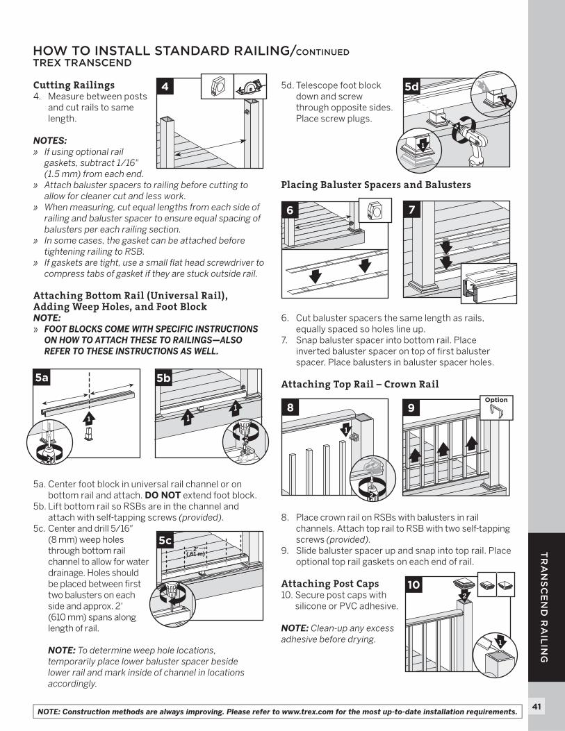
Cutting Railings4. Measure between posts
and cut rails to same length.
NOTES:» If using optional rail
gaskets, subtract 1/16" (1.5 mm) from each end.
» Attach baluster spacers to railing before cutting to allow for cleaner cut and less work.
» When measuring, cut equal lengths from each side of railing and baluster spacer to ensure equal spacing of balusters per each railing section.
» In some cases, the gasket can be attached before tightening railing to RSB.
» If gaskets are tight, use a small fl at head screwdriver to compress tabs of gasket if they are stuck outside rail.
Attaching Bottom Rail (Universal Rail), Adding Weep Holes, and Foot BlockNOTE:» FOOT BLOCKS COME WITH SPECIFIC INSTRUCTIONS
ON HOW TO ATTACH THESE TO RAILINGS—ALSO REFER TO THESE INSTRUCTIONS AS WELL.
5a. Center foot block in universal rail channel or on bottom rail and attach. DO NOT extend foot block.
5b. Lift bottom rail so RSBs are in the channel and attach with self-tapping screws (provided).
5c. Center and drill 5/16"(8 mm) weep holes through bottom rail channel to allow for water drainage. Holes should be placed between fi rst two balusters on each side and approx. 2'(610 mm) spans along length of rail.
NOTE: To determine weep hole locations, temporarily place lower baluster spacer beside lower rail and mark inside of channel in locations accordingly.
5d. Telescope foot block down and screw through opposite sides. Place screw plugs.
Placing Baluster Spacers and Balusters
6. Cut baluster spacers the same length as rails, equally spaced so holes line up.
7. Snap baluster spacer into bottom rail. Place inverted baluster spacer on top of fi rst baluster spacer. Place balusters in baluster spacer holes.
Attaching Top Rail – Crown Rail
8. Place crown rail on RSBs with balusters in rail channels. Attach top rail to RSB with two self-tapping screws (provided).
9. Slide baluster spacer up and snap into top rail. Place optional top rail gaskets on each end of rail.
Attaching Post Caps10. Secure post caps with
silicone or PVC adhesive.
NOTE: Clean-up any excess adhesive before drying.
HOW TO INSTALL STANDARD RAILING/CONTINUEDTREX TRANSCEND
6 7
1
5a
2
11
5b
2
4
2
5d 23
3
1
5c2’
(.61 m)
1
8
x2
2
2
9Option
2
2
10
3
1
42
TR
AN
SC
EN
D R
AIL
ING
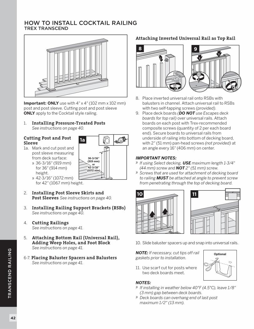
Important: ONLY use with 4" x 4" (102 mm x 102 mm) post and post sleeve. Cutting post and post sleeve ONLY apply to the Cocktail style railing.
1. Installing Pressure-Treated Posts See instructions on page 40.
Cutting Post and Post Sleeve 1a. Mark and cut post and
post sleeve measuring from deck surface:
» 36-3/16" (919 mm) for 36" (914 mm) height.
» 42-3/16" (1072 mm) for 42" (1067 mm) height.
2. Installing Post Sleeve Skirts and Post Sleeves See instructions on page 40.
3. Installing Railing Support Brackets (RSBs) See instructions on page 40. 4. Cutting Railings
See instructions on page 41. 5. Attaching Bottom Rail (Universal Rail),
Adding Weep Holes, and Foot Block See instructions on page 41.
6-7. Placing Baluster Spacers and Balusters See instructions on page 41.
Attaching Inverted Universal Rail as Top Rail
8. Place inverted universal rail onto RSBs with balusters in channel. Attach universal rail to RSBs with two self-tapping screws (provided).
9. Place deck boards (DO NOT use Escapes deck boards for top rail) over universal rails. Attach boards on each post with Trex-recommended composite screws (quantity of 2 per each board end). Secure boards to universal rails from underside of railing into bottom of decking board, with 2" (51 mm) pan-head screws (not provided) at an angle every 16" (406 mm) on center.
IMPORTANT NOTES: » If using Select decking, USE maximum length 1-3/4"
(44 mm) screw and NOT 2" (51 mm) screw.» Screws that are used for attachment of decking board
to railing MUST be attached at angle to prevent screw from penetrating through the top of decking board.
10. Slide baluster spacers up and snap into universal rails.
NOTE: If necessary, cut tips off rail gaskets prior to installation.
11. Use scarf cut for posts where two deck boards meet.
NOTES: » If installing in weather below 40°F (4.5°C), leave 1/8"
(3 mm) gap between deck boards.» Deck boards can overhang end of last post
maximum 1/2" (13 mm).
HOW TO INSTALL COCKTAIL RAILINGTREX TRANSCEND
36-3/16"(919 mm)
or42-3/16"
(1072 mm)
36-3/16"(919 mm)
or42-3/16"
(1072 mm)
1a
11
9
2
3
1
8
2
10 11
Optional
43
TR
AN
SC
EN
D R
AIL
ING
NOTE: Construction methods are always improving. Please refer to www.trex.com for the most up-to-date installation requirements.
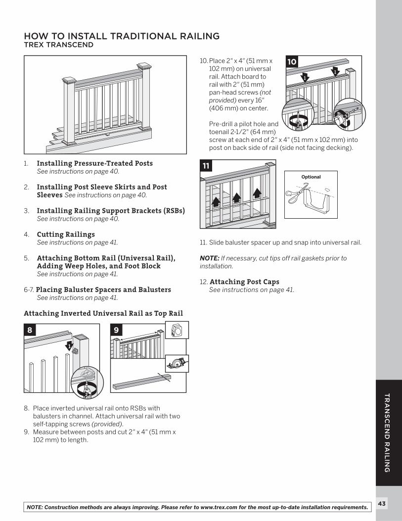
1. Installing Pressure-Treated PostsSee instructions on page 40.
2. Installing Post Sleeve Skirts and Post Sleeves See instructions on page 40.
3. Installing Railing Support Brackets (RSBs)See instructions on page 40.
4. Cutting RailingsSee instructions on page 41.
5. Attaching Bottom Rail (Universal Rail), Adding Weep Holes, and Foot BlockSee instructions on page 41.
6-7. Placing Baluster Spacers and BalustersSee instructions on page 41.
Attaching Inverted Universal Rail as Top Rail
8. Place inverted universal rail onto RSBs with balusters in channel. Attach universal rail with two self-tapping screws (provided).
9. Measure between posts and cut 2" x 4" (51 mm x 102 mm) to length.
10. Place 2" x 4" (51 mm x 102 mm) on universal rail. Attach board to rail with 2" (51 mm) pan-head screws (not provided) every 16"(406 mm) on center.
Pre-drill a pilot hole and toenail 2-1/2" (64 mm) screw at each end of 2" x 4" (51 mm x 102 mm) into post on back side of rail (side not facing decking).
11. Slide baluster spacer up and snap into universal rail.
NOTE: If necessary, cut tips off rail gaskets prior to installation.
12. Attaching Post CapsSee instructions on page 41.
HOW TO INSTALL TRADITIONAL RAILINGTREX TRANSCEND
9
1
1
8
x2
2
11
10
3
2
11Optional
44
TR
AN
SC
EN
D R
AIL
ING
NOTE: Construction methods are always improving. Please refer to www.trex.com for the most up-to-date installation requirements.
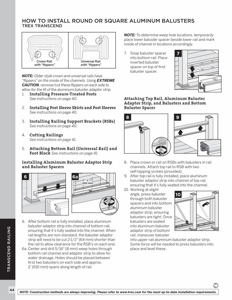
NOTE: Older style crown and universal rails have "fl ippers" on the inside of the channels. Using EXTREME CAUTION, remove/cut these fl ippers on each side to allow for the fi t of the aluminum baluster adaptor strip. 1. Installing Pressure-Treated Posts
See instructions on page 40.
2. Installing Post Sleeve Skirts and Post SleevesSee instructions on page 40.
3. Installing Railing Support Brackets (RSBs)See instructions on page 40.
4. Cutting RailingsSee instructions on page 41.
5. Attaching Bottom Rail (Universal Rail) and Foot Block See instructions on page 41.
Installing Aluminum Baluster Adaptor Strip and Baluster Spacers
6. After bottom rail is fully installed, place aluminum baluster adaptor strip into channel of bottom rail, ensuring that it’s fully seated into the channel. When rail lengths are non-standard, the baluster adaptor strip will need to be cut 2-1/2" (64 mm) shorter than the rail to allow clearance for the RSB’s on each end.
6a. Center and drill 5/16" (8 mm) weep holes through bottom rail channel and adaptor strip to allow for water drainage. Holes should be placed between fi rst two balusters on each side and approx. 2' (610 mm) spans along length of rail.
NOTE: To determine weep hole locations, temporarily place lower baluster spacer beside lower rail and mark inside of channel in locations accordingly.
7. Snap baluster spacer into bottom rail. Place inverted baluster spacer on top of fi rst baluster spacer.
Attaching Top Rail, Aluminum Baluster Adaptor Strip, and Balusters and Bottom Baluster Spacer
8. Place crown or rail on RSBs with balusters in rail channels. Attach top rail to RSB with two self-tapping screws (provided).
9. After top rail is fully installed, place aluminum baluster adaptor strip into channel of top rail, ensuring that it’s fully seated into the channel.
10. Working at slight angle, press baluster through both baluster spacers and into bottom aluminum baluster adaptor strip, ensuring balusters are tight. Once balusters are seated into aluminum baluster adaptor strip of bottom rail, maneuver baluster into upper rail aluminum baluster adaptor strip. Some force will be needed to press balusters into place and level these.
HOW TO INSTALL ROUND OR SQUARE ALUMINUM BALUSTERSTREX TRANSCEND
Crown Rail with “flippers”
Universal Rail with “flippers”
6
7
1
8
x2
2
9
6a2'
(610 mm)2'
(610 mm)
2
1
10
45
TR
AN
SC
EN
D R
AIL
ING
HOW TO INSTALL ROUND OR SQUARE ALUMINUM BALUSTERS/CONTINUEDTREX TRANSCEND
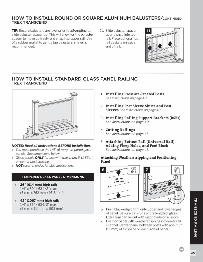
TIP: Ensure balusters are level prior to attempting to slide baluster spacer up. This will allow for the baluster spacer to move up freely and snap into upper rail. Use of a rubber mallet to gently tap balusters in level is recommended.
11. Slide baluster spacer up and snap into top rail. Place optional top rail gaskets on each end of rail.
2
11
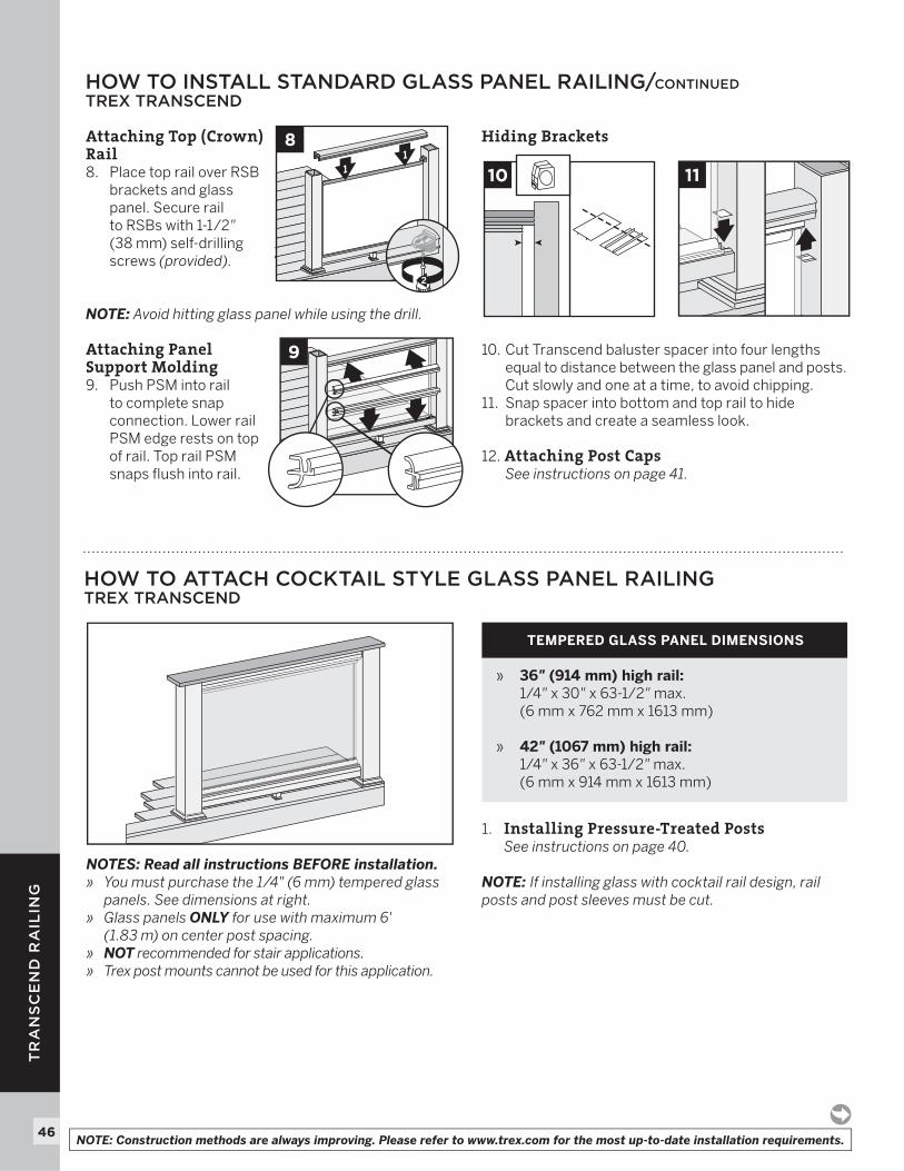
HOW TO INSTALL STANDARD GLASS PANEL RAILING TREX TRANSCEND
NOTES: Read all instructions BEFORE installation.» You must purchase the 1/4" (6 mm) tempered glass
panels. See dimensions below.» Glass panels ONLY for use with maximum 6' (1.83 m)
on center post spacing.» NOT recommended for stair applications.
1. Installing Pressure-Treated Posts See instructions on page 40.
2. Installing Post Sleeve Skirts and Post Sleeves See instructions on page 40.
3. Installing Railing Support Brackets (RSBs)See instructions on page 40.
4. Cutting Railings See instructions on page 41.
5. Attaching Bottom Rail (Universal Rail), Adding Weep Holes, and Foot Block
See instructions on page 41.
Attaching Weatherstripping and Positioning Panel
6. Push black-edged trim onto upper and lower edges of panel. Be sure trim runs entire length of glass. Extra trim can be cut with razor blade or scissors.
7. Position panel with weatherstripping into lower rail channel. Center panel between posts with about 2" (51 mm) of air space on each side of panel.
TEMPERED GLASS PANEL DIMENSIONS
» 36" (914 mm) high rail:1/4" x 30" x 63-1/2" max. (6 mm x 762 mm x 1613 mm)
» 42" (1067 mm) high rail:1/4" x 36" x 63-1/2" max.(6 mm x 914 mm x 1613 mm)
7
2" (51 mm)2" (51 mm)
63-1/2"(1613 mm)
6
46
TR
AN
SC
EN
D R
AIL
ING
NOTE: Construction methods are always improving. Please refer to www.trex.com for the most up-to-date installation requirements.
Attaching Top (Crown) Rail8. Place top rail over RSB
brackets and glass panel. Secure rail to RSBs with 1-1/2"(38 mm) self-drilling screws (provided).
NOTE: Avoid hitting glass panel while using the drill.
Attaching Panel Support Molding9. Push PSM into rail
to complete snap connection. Lower rail PSM edge rests on top of rail. Top rail PSM snaps fl ush into rail.
Hiding Brackets
10. Cut Transcend baluster spacer into four lengths equal to distance between the glass panel and posts. Cut slowly and one at a time, to avoid chipping. 11. Snap spacer into bottom and top rail to hide
brackets and create a seamless look.
12. Attaching Post CapsSee instructions on page 41.
11
8
2
9
HOW TO INSTALL STANDARD GLASS PANEL RAILING/CONTINUED TREX TRANSCEND
1110
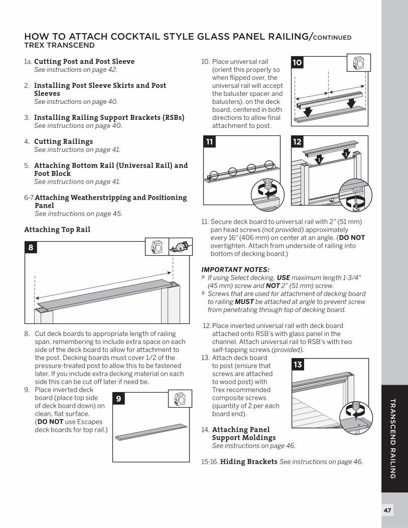
HOW TO ATTACH COCKTAIL STYLE GLASS PANEL RAILINGTREX TRANSCEND
TEMPERED GLASS PANEL DIMENSIONS
» 36" (914 mm) high rail:1/4" x 30" x 63-1/2" max. (6 mm x 762 mm x 1613 mm)
» 42" (1067 mm) high rail:1/4" x 36" x 63-1/2" max.(6 mm x 914 mm x 1613 mm)
NOTES: Read all instructions BEFORE installation.» You must purchase the 1/4 " (6 mm) tempered glass
panels. See dimensions at right.» Glass panels ONLY for use with maximum 6'
(1.83 m) on center post spacing.» NOT recommended for stair applications.» Trex post mounts cannot be used for this application.
1. Installing Pressure-Treated Posts See instructions on page 40.
NOTE: If installing glass with cocktail rail design, rail posts and post sleeves must be cut.
47
TR
AN
SC
EN
D R
AIL
ING
1a. Cutting Post and Post Sleeve See instructions on page 42.
2. Installing Post Sleeve Skirts and Post Sleeves See instructions on page 40.
3. Installing Railing Support Brackets (RSBs)See instructions on page 40.
4. Cutting Railings See instructions on page 41.
5. Attaching Bottom Rail (Universal Rail) and Foot Block
See instructions on page 41.
6-7. Attaching Weatherstripping and Positioning PanelSee instructions on page 45.
Attaching Top Rail
8. Cut deck boards to appropriate length of railing span, remembering to include extra space on each side of the deck board to allow for attachment to the post. Decking boards must cover 1/2 of the pressure-treated post to allow this to be fastened later. If you include extra decking material on each side this can be cut off later if need be.
9. Place inverted deck board (place top side of deck board down) on clean, fl at surface. (DO NOT use Escapes deck boards for top rail.)
10. Place universal rail (orient this properly so when fl ipped over, the universal rail will accept the baluster spacer and balusters), on the deck board, centered in both directions to allow fi nal attachment to post.
11. Secure deck board to universal rail with 2" (51 mm) pan head screws (not provided) approximately every 16" (406 mm) on center at an angle. (DO NOT overtighten. Attach from underside of railing into bottom of decking board.)
IMPORTANT NOTES:» If using Select decking, USE maximum length 1-3/4"
(45 mm) screw and NOT 2" (51 mm) screw.» Screws that are used for attachment of decking board
to railing MUST be attached at angle to prevent screw from penetrating through top of decking board.
12. Place inverted universal rail with deck board attached onto RSB’s with glass panel in the channel. Attach universal rail to RSB’s with two self-tapping screws (provided).
13. Attach deck board to post (ensure that screws are attached to wood post) with Trex recommended composite screws (quantity of 2 per each board end).
14. Attaching Panel Support MoldingsSee instructions on page 46.
15-16. Hiding Brackets See instructions on page 46.
10
9
HOW TO ATTACH COCKTAIL STYLE GLASS PANEL RAILING/CONTINUEDTREX TRANSCEND
8
11
11
12
2
13
48
TR
AN
SC
EN
D R
AIL
ING
NOTE: Construction methods are always improving. Please refer to www.trex.com for the most up-to-date installation requirements.
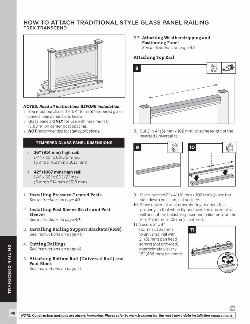
NOTES: Read all instructions BEFORE installation.» You must purchase the 1/4" (6 mm) tempered glass
panels. See dimensions below.» Glass panels ONLY for use with maximum 6'
(1.83 m) on center post spacing.» NOT recommended for stair applications.
1. Installing Pressure-Treated Posts See instructions on page 40.
2. Installing Post Sleeve Skirts and Post Sleeves See instructions on page 40.
3. Installing Railing Support Brackets (RSBs)See instructions on page 40.
4. Cutting Railings See instructions on page 41.
5. Attaching Bottom Rail (Universal Rail) and Foot Block
See instructions on page 41.
6-7. Attaching Weatherstripping and Positioning PanelSee instructions on page 45.
Attaching Top Rail
8. Cut 2" x 4" (51 mm x 102 mm) to same length of the inverted Universal rail.
9. Place inverted 2" x 4" (51 mm x 102 mm) (place top side down) on clean, fl at surface.
10. Place universal rail (remembering to orient this properly so that when fl ipped over, the universal rail will accept the baluster spacer and balusters), on the 2" x 4" (51 mm x 102 mm), centered.
11. Secure 2" x 4" (51 mm x 102 mm) to universal rail with 2" (51 mm) pan head screws (not provided)approximately every 16" (406 mm) on center.
HOW TO ATTACH TRADITIONAL STYLE GLASS PANEL RAILINGTREX TRANSCEND
TEMPERED GLASS PANEL DIMENSIONS
» 36" (914 mm) high rail:1/4" x 30" x 63-1/2" max. (6 mm x 762 mm x 1613 mm)
» 42" (1067 mm) high rail:1/4" x 36" x 63-1/2" max.(6 mm x 914 mm x 1613 mm)
109
8
11
49
TR
AN
SC
EN
D R
AIL
ING
HOW TO ATTACH TRADITIONAL STYLE GLASS PANEL RAILING/CONTINUEDTREX TRANSCEND
12. Place inverted universal rail with 2" x 4" (51 mm x 102 mm) attached onto RSB’s with glass panel in the channel. Attach universal rail to RSB’s with two self-tapping screws (not provided).13. Pre-drill a pilot hole and toenail 2-1/2" (64 mm)
screw at each end of the 2" x 4" (51 mm x 102 mm)into post on back side (side not facing decking).
14. Attaching Panel Support MoldingsSee instructions on page 46.
15-16. Hiding BracketsSee instructions on page 46.
17. Attaching Post CapsSee instructions on page 41.
11
12
2
13
3
HOW TO INSTALL ON-AN-ANGLE RAILINGTREX TRANSCEND (CROWN AND UNIVERSAL RAILING)
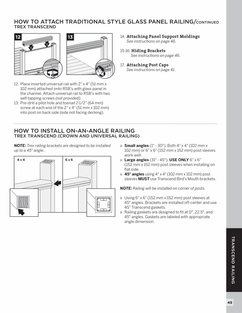
NOTE: Trex railing brackets are designed to be installed up to a 45° angle.
» Small angles (1° - 30°). Both 4" x 4" (102 mm x 102 mm) or 6" x 6" (152 mm x 152 mm) post sleeves work well.
» Large angles (31° - 45°). USE ONLY 6" x 6"(152 mm x 152 mm) post sleeves when installing on fl at side.
» 45° angles using 4" x 4" (102 mm x 102 mm) post sleeves MUST use Transcend Bird’s Mouth brackets.
NOTE: Railing will be installed on corner of posts.
» Using 6" x 6" (152 mm x 152 mm) post sleeves at 45° angles. Brackets are installed off-center and use 45° Transcend gaskets.» Railing gaskets are designed to fi t at 0°, 22.5°, and
45° angles. Gaskets are labeled with appropriate angle dimension.
4 x 4 6 x 6
50
TR
AN
SC
EN
D R
AIL
ING
NOTE: Construction methods are always improving. Please refer to www.trex.com for the most up-to-date installation requirements.
HOW TO INSTALL CROWN AND UNIVERSAL BIRD'S MOUTH RAILINGTREX TRANSCEND NOTES: » Use with 4" x 4" (102 mm x 102 mm) post sleeve ONLY. » Gaskets are only designed for use with Transcend
crown and universal railing.
Read all instructions BEFORE installation.
PARTS
Mark Posts 1. Measure and mark
4" (102 mm) and 33-9/16" (852 mm) up from top of post skirt. For a 42" (1067 mm) rail, top mark is 39-9/16" (1005 mm) on post.
NOTE: Without skirt,add 1-1/2" (38 mm) to measurements.
Attaching Adaptors Snap adaptors into RSBs.
Pre-Drill Bottom and Top RSBs
2. Position RSBs with adaptor (flat side DOWN) for lower rail, mark and pre-drill screw holes with 1/8" (3 mm) drill bit on post.
3. Position RSBs with adaptor (flat side UP) for top rail, mark and pre-drill screw holes with 1/8" (3 mm) drill bit on post.
Measuring and Cutting Rails
4. Measure from corner-to-corner between posts. Mark 45° cuts on rails with template on assembly tool. Center of “V’s” is the distance from corner-to-corner for posts.
NOTE: Subtract 1/16" (1.6 mm) from each end to accommodate rail gaskets.
Attaching Top and Bottom RSBs 5. Attach RSBs with adaptors
to posts with wood screws (provided).
NOTES: » Drill at slight inward angle to
drill holes on marks.» Lay cut lower rail into position
on decking surface between the posts before attaching the lower RSB. There may be some difficulty attaching the lower rail if you fail to do this.
1
4" (102 mm)
33-9/16"(852 mm)
for 36"or
39-9/16"(1005 mm)
for 42"
33-9/16"(852 mm)
for 36"or
39-9/16"(1005 mm)
for 42"
32
4
5
51
TR
AN
SC
EN
D R
AIL
ING
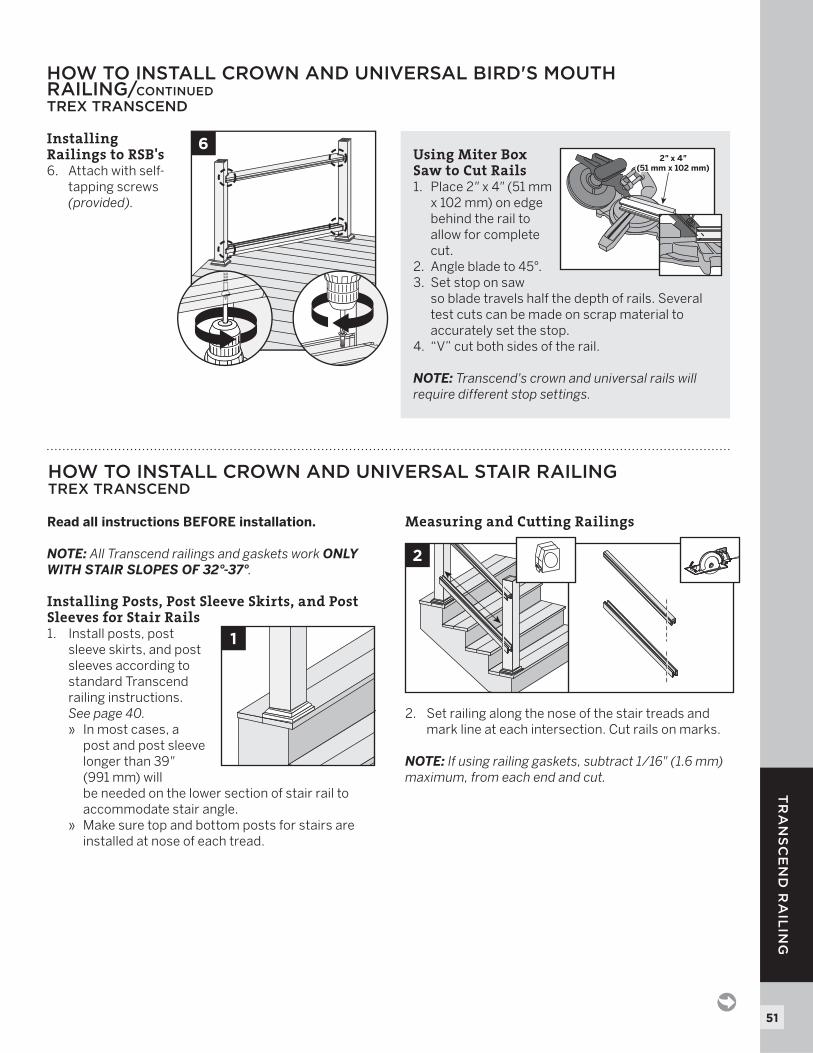
Installing Railings to RSB's6. Attach with self-
tapping screws (provided).
HOW TO INSTALL CROWN AND UNIVERSAL BIRD'S MOUTHRAILING/CONTINUEDTREX TRANSCEND
6 Using Miter Box Saw to Cut Rails
1. Place 2" x 4" (51 mm x 102 mm) on edge behind the rail to allow for complete cut.
2. Angle blade to 45°. 3. Set stop on saw
so blade travels half the depth of rails. Several test cuts can be made on scrap material to accurately set the stop.
4. “V” cut both sides of the rail.
NOTE: Transcend's crown and universal rails will require different stop settings.
2" x 4"(51 mm x 102 mm)
2" x 4"(51 mm x 102 mm)
Read all instructions BEFORE installation.
NOTE: All Transcend railings and gaskets work ONLY WITH STAIR SLOPES OF 32°-37°.
Installing Posts, Post Sleeve Skirts, and Post Sleeves for Stair Rails1. Install posts, post
sleeve skirts, and post sleeves according to standard Transcend railing instructions. See page 40.
» In most cases, a post and post sleeve longer than 39" (991 mm) will be needed on the lower section of stair rail to accommodate stair angle.
» Make sure top and bottom posts for stairs are installed at nose of each tread.
Measuring and Cutting Railings
2. Set railing along the nose of the stair treads and mark line at each intersection. Cut rails on marks.
NOTE: If using railing gaskets, subtract 1/16" (1.6 mm) maximum, from each end and cut.
HOW TO INSTALL CROWN AND UNIVERSAL STAIR RAILINGTREX TRANSCEND
1
2
52
TR
AN
SC
EN
D R
AIL
ING
NOTE: Construction methods are always improving. Please refer to www.trex.com for the most up-to-date installation requirements.
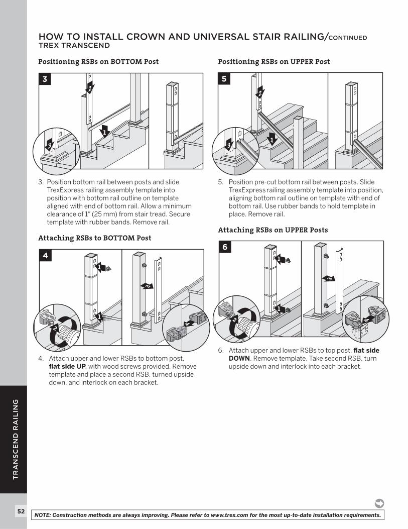
Positioning RSBs on BOTTOM Post
3. Position bottom rail between posts and slide TrexExpress railing assembly template into position with bottom rail outline on template aligned with end of bottom rail. Allow a minimum clearance of 1" (25 mm) from stair tread. Secure template with rubber bands. Remove rail.
Attaching RSBs to BOTTOM Post
4. Attach upper and lower RSBs to bottom post,fl at side UP, with wood screws provided. Remove template and place a second RSB, turned upside down, and interlock on each bracket.
Positioning RSBs on UPPER Post
5. Position pre-cut bottom rail between posts. Slide TrexExpress railing assembly template into position, aligning bottom rail outline on template with end of bottom rail. Use rubber bands to hold template in place. Remove rail.
Attaching RSBs on UPPER Posts
6. Attach upper and lower RSBs to top post, fl at side DOWN. Remove template. Take second RSB, turn upside down and interlock into each bracket.
3
1
1
6
42
2
1
5
3
1
2
1
3
3
3
1
1
4
42
HOW TO INSTALL CROWN AND UNIVERSAL STAIR RAILING/CONTINUEDTREX TRANSCEND
53
TR
AN
SC
EN
D R
AIL
ING
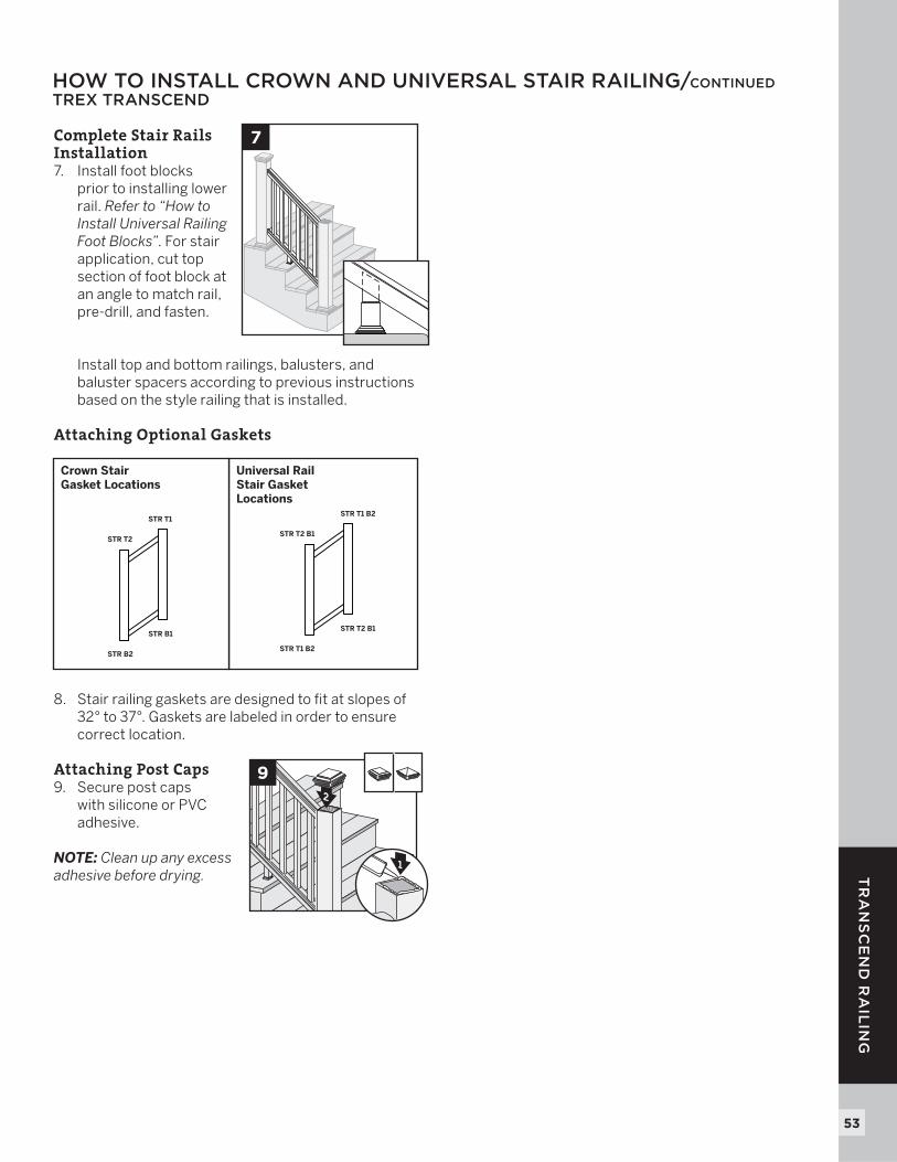
Complete Stair Rails Installation7. Install foot blocks
prior to installing lower rail. Refer to “How to Install Universal Railing Foot Blocks”. For stair application, cut top section of foot block at an angle to match rail, pre-drill, and fasten.
Install top and bottom railings, balusters, and baluster spacers according to previous instructions based on the style railing that is installed.
Attaching Optional Gaskets
8. Stair railing gaskets are designed to fit at slopes of 32° to 37°. Gaskets are labeled in order to ensure correct location.
Attaching Post Caps 9. Secure post caps
with silicone or PVC adhesive.
NOTE: Clean up any excess adhesive before drying.
HOW TO INSTALL CROWN AND UNIVERSAL STAIR RAILING/CONTINUED TREX TRANSCEND
2
9
3
1
Universal RailStair GasketLocations
STR T2 B1
STR T1 B2
STR T1 B2
STR T2 B1
Crown Stair Gasket Locations
STR T2
STR T1
STR B2
STR B1
7
54
RE
VE
AL
RA
ILIN
G
G
C
I
A
D
K
L
J
E
B
H
H
I
K
MN
O
P
F
Square Round
BALUSTER OPTIONS
NOTES:
» REVEAL RAILINGS ARE DESIGNED TO BE ATTACHED WITH POSTS INSTALLED AT A CLEAR SPAN OF 6' (1.83 M) OR 8' (2.44 M).
» IF INSTALLING AT EXACT SPAN LENGTHS OF 6' (1.83 M) OR 8' (2.44 M), AND USING POST-TO-POST CONFIGURATION, THE BOTTOM RAIL WILL NOT NEED TO BE CUT, BUT THE TOP RAIL WILL NEED TO BE MEASURED (MAKING SURE BALUSTERS LINE UP VERTICALLY) AND CUT.
» IF INSTALLING AT EXACT SPAN LENGTHS OF 6' (1.83 M) OR 8' (2.44 M), AND USING CROSSOVER POST CONFIGURATION (SPANS FROM ONE CROSSOVER POST TO ANOTHER CROSSOVER POST), BOTH THE BOTTOM RAIL AND TOP RAIL WILL NOT NEED TO BE CUT.
» IN ADDITION, AT ALL FINAL END POST CONFIGURATIONS, TOP RAIL WILL NEED TO BE MEASURED (MAKING SURE BALUSTERS LINE UP VERTICALLY) AND CUT.
» FOR ODD SPAN LENGTHS, BOTH TOP RAIL AND BOTTOM RAIL WILL NEED TO BE MEASURED (MAKING SURE BALUSTERS LINE UP VERTICALLY) AND CUT. ENSURE THAT BALUSTERS ARE SPACED WITH AN EQUAL DISTANCE ON EACH SIDE OF THE POST.
» WHEN RAILINGS ARE CUT TO ODD SPANS, ALL SPANS GREATER THAN 5' (1.52 M) (EXAMPLE: 8' (2.44 M) SPAN CUT INTO ONE 5' (1.52 M) SPAN AND ONE 3' (0.91 M) SPAN) WOULD REQUIRE FOOT BLOCK UNDER 5' (1.52 M) SPAN SINCE SMALLER FIXED BALUSTER IS NO LONGER CENTERED).
DETERMINING BALUSTERS NEEDED
Baluster Type
Per 6' Section
Per 8' Section
Per 6' Stair Section
Per 8' Stair Section
Square 15 20 13 17
Round 15 20 13 17
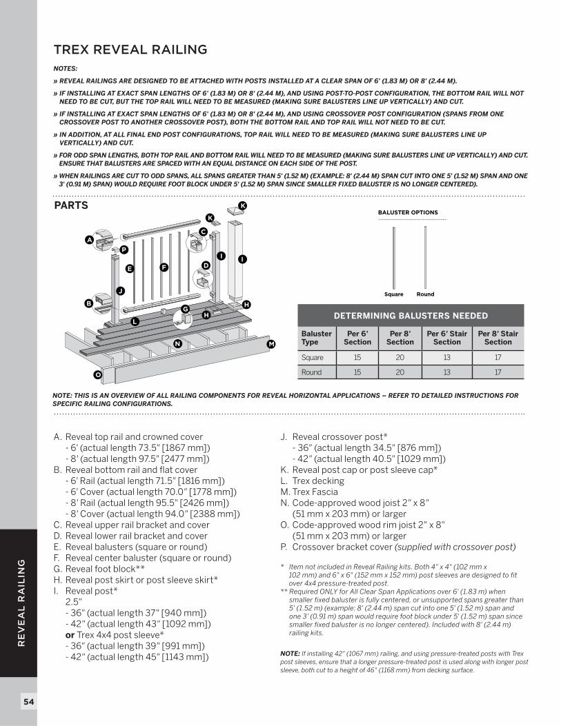
A. Reveal top rail and crowned cover - 6' (actual length 73.5" [1867 mm]) - 8' (actual length 97.5" [2477 mm])B. Reveal bottom rail and flat cover - 6' Rail (actual length 71.5" [1816 mm]) - 6' Cover (actual length 70.0" [1778 mm]) - 8' Rail (actual length 95.5" [2426 mm]) - 8' Cover (actual length 94.0" [2388 mm])C. Reveal upper rail bracket and coverD. Reveal lower rail bracket and coverE. Reveal balusters (square or round)F. Reveal center baluster (square or round)G. Reveal foot block**H. Reveal post skirt or post sleeve skirt*I. Reveal post* 2.5" - 36" (actual length 37" [940 mm]) - 42" (actual length 43" [1092 mm]) or Trex 4x4 post sleeve* - 36" (actual length 39" [991 mm]) - 42" (actual length 45" [1143 mm])
NOTE: THIS IS AN OVERVIEW OF ALL RAILING COMPONENTS FOR REVEAL HORIZONTAL APPLICATIONS – REFER TO DETAILED INSTRUCTIONS FOR SPECIFIC RAILING CONFIGURATIONS.
J. Reveal crossover post* - 36" (actual length 34.5" [876 mm]) - 42" (actual length 40.5" [1029 mm]) K. Reveal post cap or post sleeve cap*L. Trex deckingM. Trex FasciaN. Code-approved wood joist 2" x 8"
(51 mm x 203 mm) or largerO. Code-approved wood rim joist 2" x 8"
(51 mm x 203 mm) or largerP. Crossover bracket cover (supplied with crossover post)
* Item not included in Reveal Railing kits. Both 4" x 4" (102 mm x 102 mm) and 6" x 6" (152 mm x 152 mm) post sleeves are designed to fit over 4x4 pressure-treated post.
** Required ONLY for All Clear Span Applications over 6' (1.83 m) when smaller fixed baluster is fully centered, or unsupported spans greater than 5' (1.52 m) (example: 8' (2.44 m) span cut into one 5' (1.52 m) span and one 3' (0.91 m) span would require foot block under 5' (1.52 m) span since smaller fixed baluster is no longer centered). Included with 8' (2.44 m) railing kits.
NOTE: If installing 42" (1067 mm) railing, and using pressure-treated posts with Trex post sleeves, ensure that a longer pressure-treated post is used along with longer post sleeve, both cut to a height of 46" (1168 mm) from decking surface.
PARTS
TREX REVEAL RAILING
55
RE
VE
AL
RA
ILIN
G
NOTE: Construction methods are always improving. Please refer to www.trex.com for the most up-to-date installation requirements.
LOCATION AND INSTALLATION OF POSTS TREX REVEAL
IMPORTANT NOTES:
» EACH POST MUST BE ATTACHED AS SHOWN TO ENSURE A CODE-COMPLIANT AND SAFE INSTALLATION.
» ALWAYS REFER TO YOUR LOCAL BUILDING CODE OFFICIAL PRIOR TO INSTALLING ANY RAILING SYSTEM TO ENSURE ALL CODE AND SAFETY REQUIREMENTS ARE MET. TREX CANNOT BE HELD RESPONSIBLE FOR IMPROPER OR NON-RECOMMENDED INSTALLATIONS.
» WHEN INSTALLING REVEAL POSTS ON ACQ OR CCA SURFACES, USE AN APPROPRIATE ISOLATION BARRIER BETWEEN POST AND SURFACE (CONTACT LOCAL BUILDING CODE OFFICIAL IF NEEDED).
» FOR INSTALLING STANDARD REVEAL POST AND/OR REVEAL CROSSOVER POSTS, SEE BELOW.
» FOR PRESSURE-TREATED POSTS, POST SLEEVES, AND SKIRTS, SEE DETAILED INSTRUCTIONS PROVIDED WITH REVEAL RAILING KITS.
» ALL REVEAL STAIR INSTALLATIONS REQUIRE THE USE OF 53" (1346 MM) STAIR POST, MEASURED AND CUT TO APPROPRIATE LENGTH IF NECESSARY.
» IF CROSSOVER STAIR POST IS REQUIRED, USE STAIR POST (AGAIN CUT TO APPROPRIATE LENGTH IF NECESSARY) AND USE SWIVEL CROSSOVER BRACKET.
TOOLS AND MATERIALS NEEDED» Drill and/or screw gun» 1/2" (13 mm) drill bit for wood» Blocking - 2" x 8" (51 mm x 203 mm) pressure-treated Southern
Yellow Pine or equivalent» Qty: 36 (per post) - 3" pressure-treated compatible wood screws
CODE APPROVED POST APPLICATIONS
POST SIZE
2.5" (64 mm)
2.5" (64 mm)
2.5 x 2.5 (64 mm x 64 mm)Post (IRC)
< 30" height decking
Acceptable(Code Approval not Applicable)
IRC Compliant Yes
IBC Compliant No
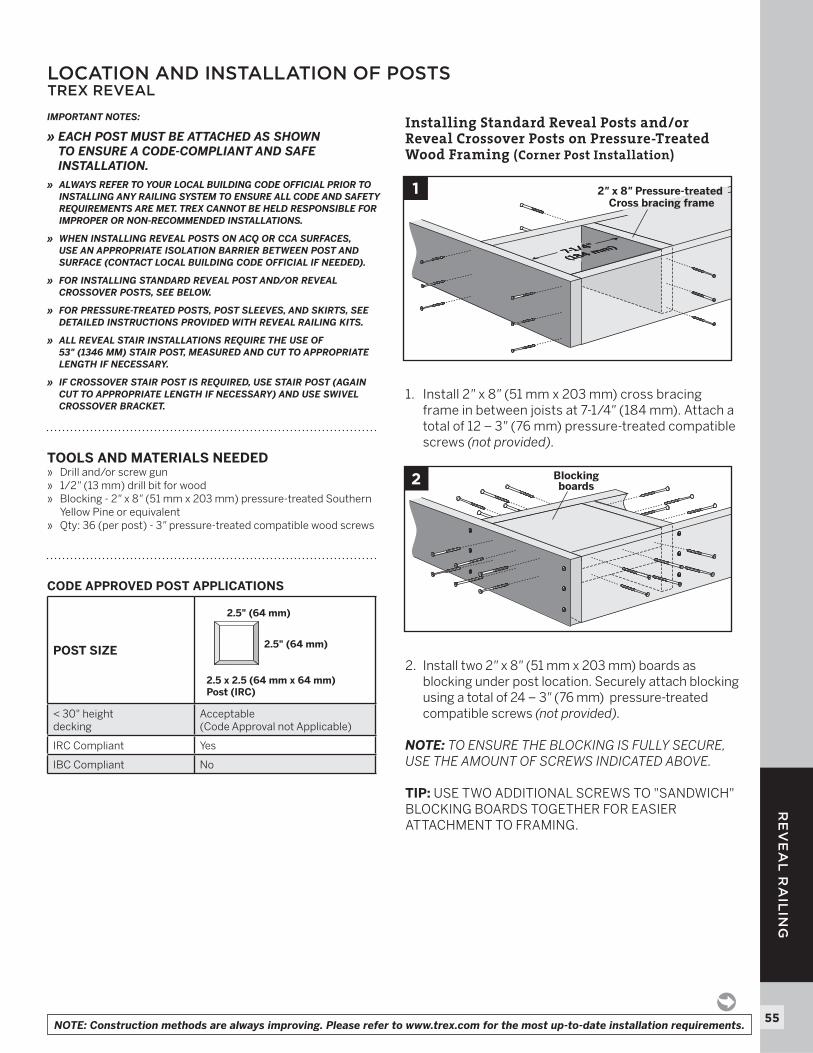
Installing Standard Reveal Posts and/or Reveal Crossover Posts on Pressure-Treated Wood Framing (Corner Post Installation)
1. Install 2" x 8" (51 mm x 203 mm) cross bracing frame in between joists at 7-1/4" (184 mm). Attach a total of 12 – 3" (76 mm) pressure-treated compatible screws (not provided).
2. Install two 2" x 8" (51 mm x 203 mm) boards as blocking under post location. Securely attach blocking using a total of 24 – 3" (76 mm) pressure-treated compatible screws (not provided).
NOTE: TO ENSURE THE BLOCKING IS FULLY SECURE, USE THE AMOUNT OF SCREWS INDICATED ABOVE.
TIP: USE TWO ADDITIONAL SCREWS TO "SANDWICH" BLOCKING BOARDS TOGETHER FOR EASIER ATTACHMENT TO FRAMING.
7-1/4"(184 mm)7-1/4"(184 mm)
2" x 8" Pressure-treated Cross bracing frame
1
2 Blockingboards
56
RE
VE
AL
RA
ILIN
G
NOTE: Construction methods are always improving. Please refer to www.trex.com for the most up-to-date installation requirements.
LOCATION AND INSTALLATION OF POSTS/CONTINUEDTREX REVEAL
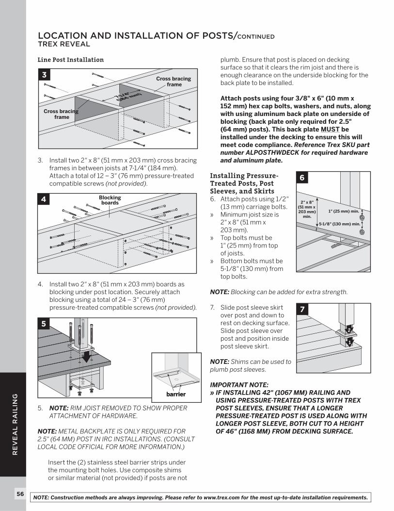
Line Post Installation
3. Install two 2" x 8" (51 mm x 203 mm) cross bracing frames in between joists at 7-1/4" (184 mm). Attach a total of 12 – 3" (76 mm) pressure-treated compatible screws (not provided).
4. Install two 2" x 8" (51 mm x 203 mm) boards as blocking under post location. Securely attach blocking using a total of 24 – 3" (76 mm) pressure-treated compatible screws (not provided).
5. NOTE: RIM JOIST REMOVED TO SHOW PROPER ATTACHMENT OF HARDWARE.
NOTE: METAL BACKPLATE IS ONLY REQUIRED FOR 2.5" (64 MM) POST IN IRC INSTALLATIONS. (CONSULT LOCAL CODE OFFICIAL FOR MORE INFORMATION.)
Insert the (2) stainless steel barrier strips under the mounting bolt holes. Use composite shims or similar material (not provided) if posts are not
plumb. Ensure that post is placed on decking surface so that it clears the rim joist and there is enough clearance on the underside blocking for the back plate to be installed.
Attach posts using four 3/8" x 6" (10 mm x 152 mm) hex cap bolts, washers, and nuts, along with using aluminum back plate on underside of blocking (back plate only required for 2.5"(64 mm) posts). This back plate MUST be installed under the decking to ensure this will meet code compliance. Reference Trex SKU part number ALPOSTHWDECK for required hardware and aluminum plate.
Installing Pressure-Treated Posts, Post Sleeves, and Skirts6. Attach posts using 1/2"
(13 mm) carriage bolts.» Minimum joist size is
2" x 8" (51 mm x 203 mm).
» Top bolts must be 1" (25 mm) from topof joists.
» Bottom bolts must be 5-1/8 " (130 mm) from top bolts.
NOTE: Blocking can be added for extra strength.
7. Slide post sleeve skirt over post and down to rest on decking surface. Slide post sleeve over post and position inside post sleeve skirt.
NOTE: Shims can be used to plumb post sleeves.
IMPORTANT NOTE:» IF INSTALLING 42" (1067 MM) RAILING AND
USING PRESSURE-TREATED POSTS WITH TREX POST SLEEVES, ENSURE THAT A LONGER PRESSURE-TREATED POST IS USED ALONG WITH LONGER POST SLEEVE, BOTH CUT TO A HEIGHT OF 46" (1168 MM) FROM DECKING SURFACE.
4 Blockingboards
5
barrierbarrier
7-1/4"(184 mm)7-1/4"(184 mm)
3 Cross bracing frame
Cross bracing frame
1
2
7
6
5-1/8" (130 mm) min.
2" x 8"(51 mm x 203 mm)
min.1" (25 mm) min.
57
RE
VE
AL
RA
ILIN
G
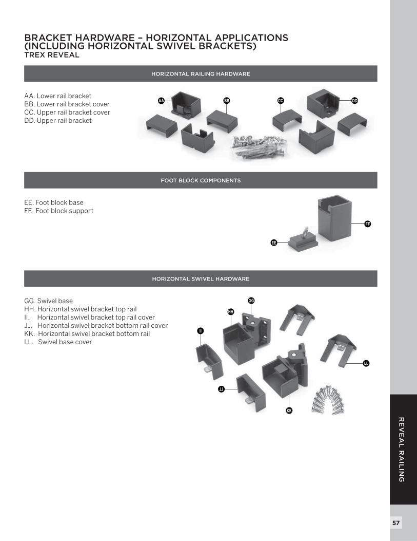
BRACKET HARDWARE – HORIZONTAL APPLICATIONS (INCLUDING HORIZONTAL SWIVEL BRACKETS) TREX REVEAL
HORIZONTAL RAILING HARDWARE
AA. Lower rail bracketBB. Lower rail bracket coverCC. Upper rail bracket coverDD. Upper rail bracket
FOOT BLOCK COMPONENTS
EE. Foot block baseFF. Foot block support
HORIZONTAL SWIVEL HARDWARE
GG. Swivel baseHH. Horizontal swivel bracket top railII. Horizontal swivel bracket top rail coverJJ. Horizontal swivel bracket bottom rail coverKK. Horizontal swivel bracket bottom railLL. Swivel base cover
FF
EE
GG
LL
KK
JJ
II
HH
AA BB CC DD
58
RE
VE
AL
RA
ILIN
G
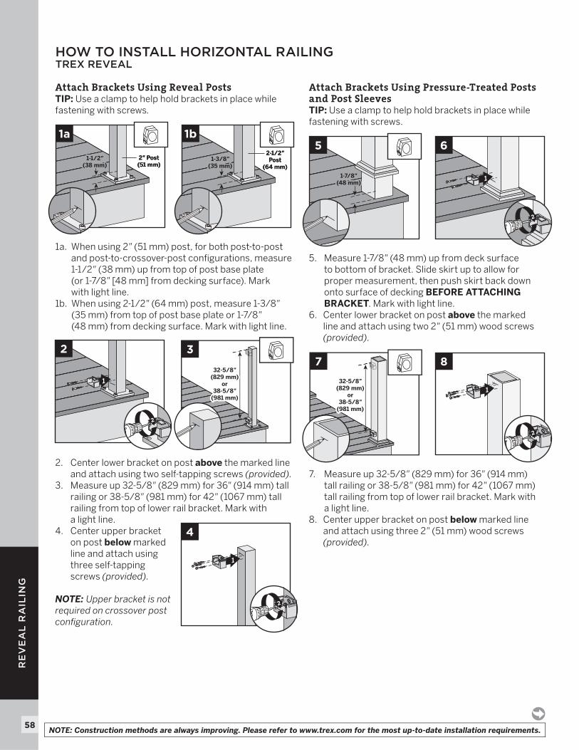
HOW TO INSTALL HORIZONTAL RAILINGTREX REVEAL
Attach Brackets Using Reveal PostsTIP: Use a clamp to help hold brackets in place while fastening with screws.
1a. When using 2" (51 mm) post, for both post-to-post and post-to-crossover-post confi gurations, measure 1-1/2" (38 mm) up from top of post base plate (or 1-7/8" [48 mm] from decking surface). Mark with light line.
1b. When using 2-1/2" (64 mm) post, measure 1-3/8" (35 mm) from top of post base plate or 1-7/8" (48 mm) from decking surface. Mark with light line.
2. Center lower bracket on post above the marked line and attach using two self-tapping screws (provided).
3. Measure up 32-5/8" (829 mm) for 36" (914 mm) tall railing or 38-5/8" (981 mm) for 42" (1067 mm) tall railing from top of lower rail bracket. Mark with a light line.
4. Center upper bracket on post below marked line and attach using three self-tapping screws (provided).
NOTE: Upper bracket is not required on crossover post confi guration.
Attach Brackets Using Pressure-Treated Posts and Post SleevesTIP: Use a clamp to help hold brackets in place while fastening with screws.
5. Measure 1-7/8" (48 mm) up from deck surface to bottom of bracket. Slide skirt up to allow for proper measurement, then push skirt back down onto surface of decking BEFORE ATTACHING BRACKET. Mark with light line.
6. Center lower bracket on post above the marked line and attach using two 2" (51 mm) wood screws (provided).
7. Measure up 32-5/8" (829 mm) for 36" (914 mm) tall railing or 38-5/8" (981 mm) for 42" (1067 mm) tall railing from top of lower rail bracket. Mark with a light line.
8. Center upper bracket on post below marked line and attach using three 2" (51 mm) wood screws (provided).
32-5/8"(829 mm)
or38-5/8"
(981 mm)
32-5/8"(829 mm)
or38-5/8"
(981 mm)
7
1
8
2
1-1/2"(38 mm)
1-1/2"(38 mm)
2" Post(51 mm)2" Post(51 mm)
1a
1-3/8"(35 mm)1-3/8"
(35 mm)
2-1/2"Post
(64 mm)
2-1/2"Post
(64 mm)
1b
1
2
2
32-5/8"(829 mm)
or38-5/8"
(981 mm)
32-5/8"(829 mm)
or38-5/8"
(981 mm)
3
1
4
2
1-7/8"(48 mm)
1-7/8"(48 mm)
5
1
6
2
NOTE: Construction methods are always improving. Please refer to www.trex.com for the most up-to-date installation requirements.
59
RE
VE
AL
RA
ILIN
G
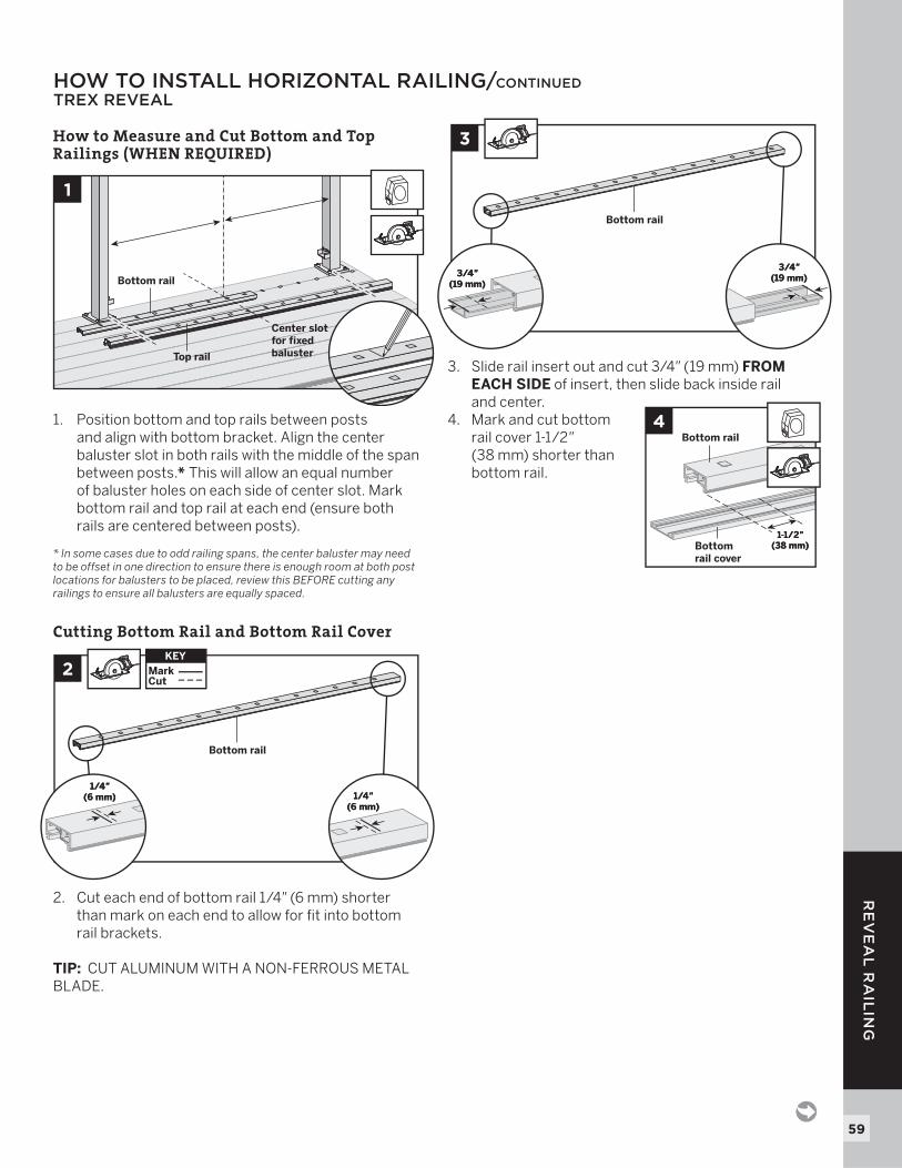
HOW TO INSTALL HORIZONTAL RAILING/CONTINUEDTREX REVEAL
How to Measure and Cut Bottom and Top Railings (WHEN REQUIRED)
1. Position bottom and top rails between posts and align with bottom bracket. Align the center baluster slot in both rails with the middle of the span between posts.* This will allow an equal number of baluster holes on each side of center slot. Mark bottom rail and top rail at each end (ensure both rails are centered between posts).
* In some cases due to odd railing spans, the center baluster may need to be offset in one direction to ensure there is enough room at both post locations for balusters to be placed, review this BEFORE cutting any railings to ensure all balusters are equally spaced.
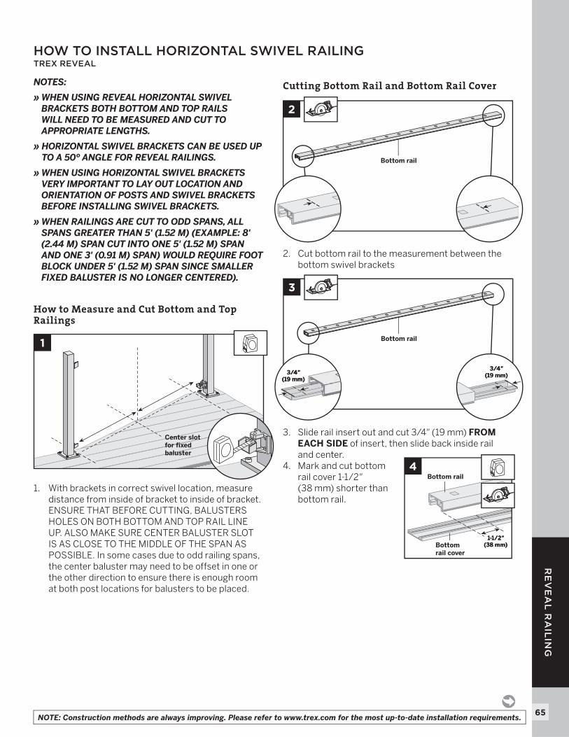
Cutting Bottom Rail and Bottom Rail Cover
2. Cut each end of bottom rail 1/4" (6 mm) shorter than mark on each end to allow for fi t into bottom rail brackets.
TIP: CUT ALUMINUM WITH A NON-FERROUS METAL BLADE.
3. Slide rail insert out and cut 3/4" (19 mm) FROM EACH SIDE of insert, then slide back inside rail and center.
4. Mark and cut bottom rail cover 1-1/2" (38 mm) shorter than bottom rail.
1
Top rail
Center slot for fixed baluster
Bottom rail
2
1/4"(6 mm)
1/4"(6 mm)
1/4"(6 mm)
1/4"(6 mm)
KEYMarkCut
KEY
Bottom rail
3
3/4"(19 mm)
3/4"(19 mm)3/4"
(19 mm)3/4"
(19 mm)
Bottom rail
1-1/2"(38 mm)
1-1/2"(38 mm)
4Bottom rail
Bottom rail cover
60
RE
VE
AL
RA
ILIN
G
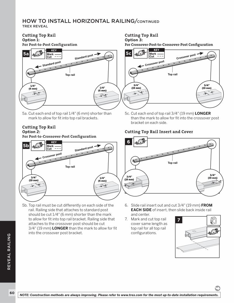
Cutting Top Rail Option 1: For Post-to-Post Configuration
5a. Cut each end of top rail 1/4" (6 mm) shorter than mark to allow for fi t into top rail brackets.
Cutting Top RailOption 2: For Post-to-Crossover-Post Configuration
5b. Top rail must be cut differently on each side of the rail. Railing side that attaches to standard post should be cut 1/4" (6 mm) shorter than the mark to allow for fi t into top rail bracket. Railing side that attaches to the crossover post should be cut 3/4" (19 mm) LONGER than the mark to allow for fi t into the crossover post bracket.
Cutting Top Rail Option 3:For Crossover-Post-to-Crossover-Post Confi guration
5c. Cut each end of top rail 3/4" (19 mm) LONGERthan the mark to allow for fi t into the crossover post bracket on each side.
Cutting Top Rail Insert and Cover
6. Slide rail insert out and cut 3/4" (19 mm) FROM EACH SIDE of insert, then slide back inside rail and center.
7. Mark and cut top rail cover same length as top rail for all top rail confi gurations.
HOW TO INSTALL HORIZONTAL RAILING/CONTINUEDTREX REVEAL
7
5a
1/4"(6 mm)
1/4"(6 mm)
1/4"(6 mm)
1/4"(6 mm)
KEYMarkCut
KEY
Top rail
Standard postStandard post 5c
3/4"(19 mm)
3/4"(19 mm)
3/4"(19 mm)
3/4"(19 mm)
KEYMarkCut
KEY
Top rail
Crossover post Crossover post
5b
1/4"(6 mm)
1/4"(6 mm)
3/4"(19 mm)
3/4"(19 mm)
KEYMarkCut
KEY
Top rail
Crossover postStandard post
6
3/4"(19 mm)
3/4"(19 mm)3/4"
(19 mm)3/4"
(19 mm)
Top rail
NOTE: Construction methods are always improving. Please refer to www.trex.com for the most up-to-date installation requirements.
61
RE
VE
AL
RA
ILIN
G
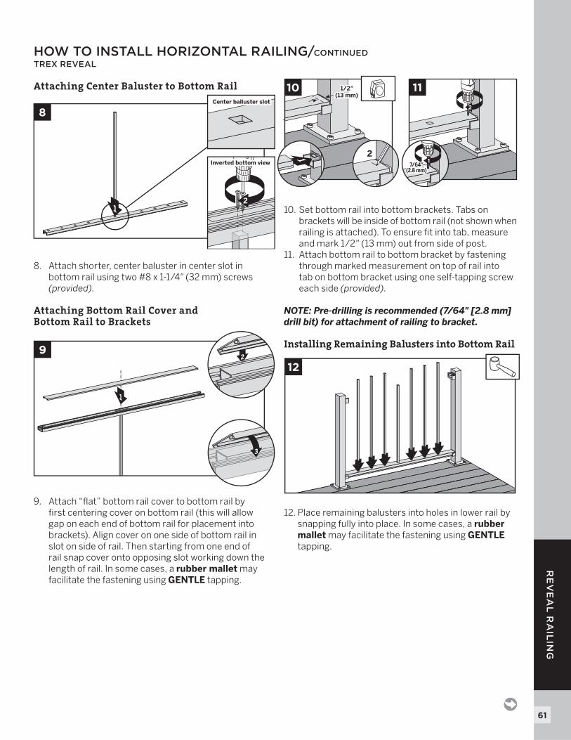
Attaching Center Baluster to Bottom Rail
8. Attach shorter, center baluster in center slot in bottom rail using two #8 x 1-1/4" (32 mm) screws (provided).
Attaching Bottom Rail Cover and Bottom Rail to Brackets
9. Attach “fl at” bottom rail cover to bottom rail by fi rst centering cover on bottom rail (this will allow gap on each end of bottom rail for placement into brackets). Align cover on one side of bottom rail in slot on side of rail. Then starting from one end of rail snap cover onto opposing slot working down the length of rail. In some cases, a rubber mallet may facilitate the fastening using GENTLE tapping.
10. Set bottom rail into bottom brackets. Tabs on brackets will be inside of bottom rail (not shown when railing is attached). To ensure fi t into tab, measure and mark 1/2" (13 mm) out from side of post.
11. Attach bottom rail to bottom bracket by fastening through marked measurement on top of rail into tab on bottom bracket using one self-tapping screw each side (provided).
NOTE: Pre-drilling is recommended (7/64" [2.8 mm] drill bit) for attachment of railing to bracket.
Installing Remaining Balusters into Bottom Rail
12. Place remaining balusters into holes in lower rail by snapping fully into place. In some cases, a rubber mallet may facilitate the fastening using GENTLEtapping.
HOW TO INSTALL HORIZONTAL RAILING/CONTINUEDTREX REVEAL
1/2"(13 mm)
1/2"(13 mm)
10
21
2
11
17/64"
(2.8 mm)7/64"
(2.8 mm)
12
1
9
3
2
1
8
Inverted bottom viewInverted bottom view
Center balluster slotCenter balluster slot
2
62
RE
VE
AL
RA
ILIN
G
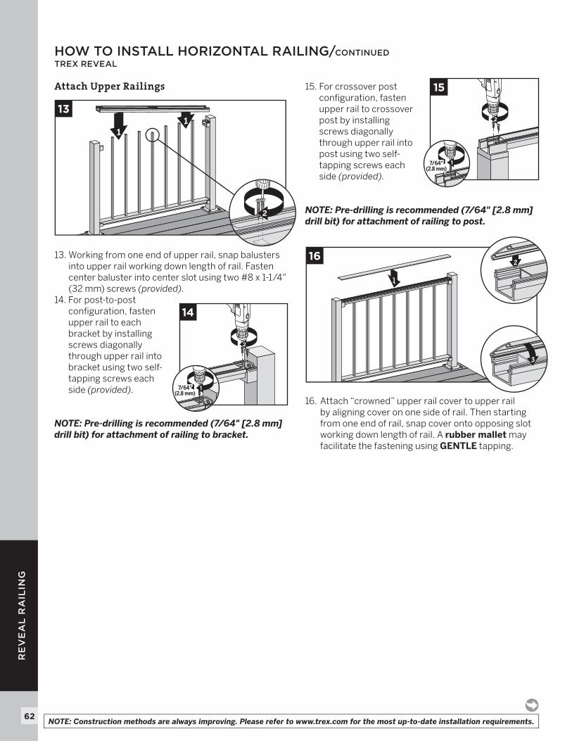
Attach Upper Railings
13. Working from one end of upper rail, snap balusters into upper rail working down length of rail. Fasten center baluster into center slot using two #8 x 1-1/4" (32 mm) screws (provided).
14. For post-to-post confi guration, fasten upper rail to each bracket by installing screws diagonally through upper rail into bracket using two self-tapping screws each side (provided).
NOTE: Pre-drilling is recommended (7/64" [2.8 mm] drill bit) for attachment of railing to bracket.
15. For crossover post confi guration, fasten upper rail to crossover post by installing screws diagonally through upper rail into post using two self-tapping screws each side (provided).
NOTE: Pre-drilling is recommended (7/64" [2.8 mm] drill bit) for attachment of railing to post.
16. Attach “crowned” upper rail cover to upper rail by aligning cover on one side of rail. Then starting from one end of rail, snap cover onto opposing slot working down length of rail. A rubber mallet may facilitate the fastening using GENTLE tapping.
HOW TO INSTALL HORIZONTAL RAILING/CONTINUEDTREX REVEAL
1
16
3
2
2
15
17/64"(2.8 mm)
7/64"(2.8 mm)
2
14
17/64"(2.8 mm)
7/64"(2.8 mm)
11
13
2
NOTE: Construction methods are always improving. Please refer to www.trex.com for the most up-to-date installation requirements.
63
RE
VE
AL
RA
ILIN
G
HOW TO INSTALL HORIZONTAL RAILING/CONTINUED TREX REVEAL
Attachment of Bracket Covers, Skirts, and Caps
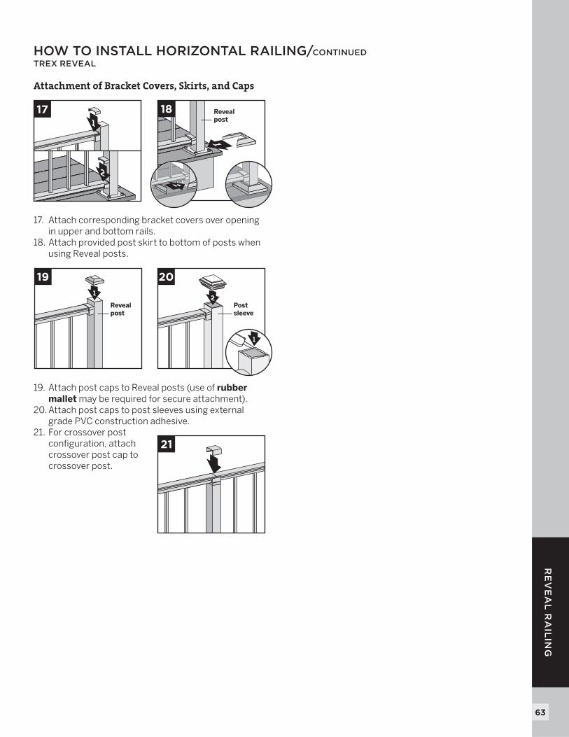
17. Attach corresponding bracket covers over opening in upper and bottom rails.
18. Attach provided post skirt to bottom of posts when using Reveal posts.
19. Attach post caps to Reveal posts (use of rubber mallet may be required for secure attachment).
20. Attach post caps to post sleeves using external grade PVC construction adhesive.
21. For crossover post configuration, attach crossover post cap to crossover post.
1
19
Revealpost
2Postsleeve
20
3
1
21
1
18 Revealpost
2
1
2
17
64
RE
VE
AL
RA
ILIN
G
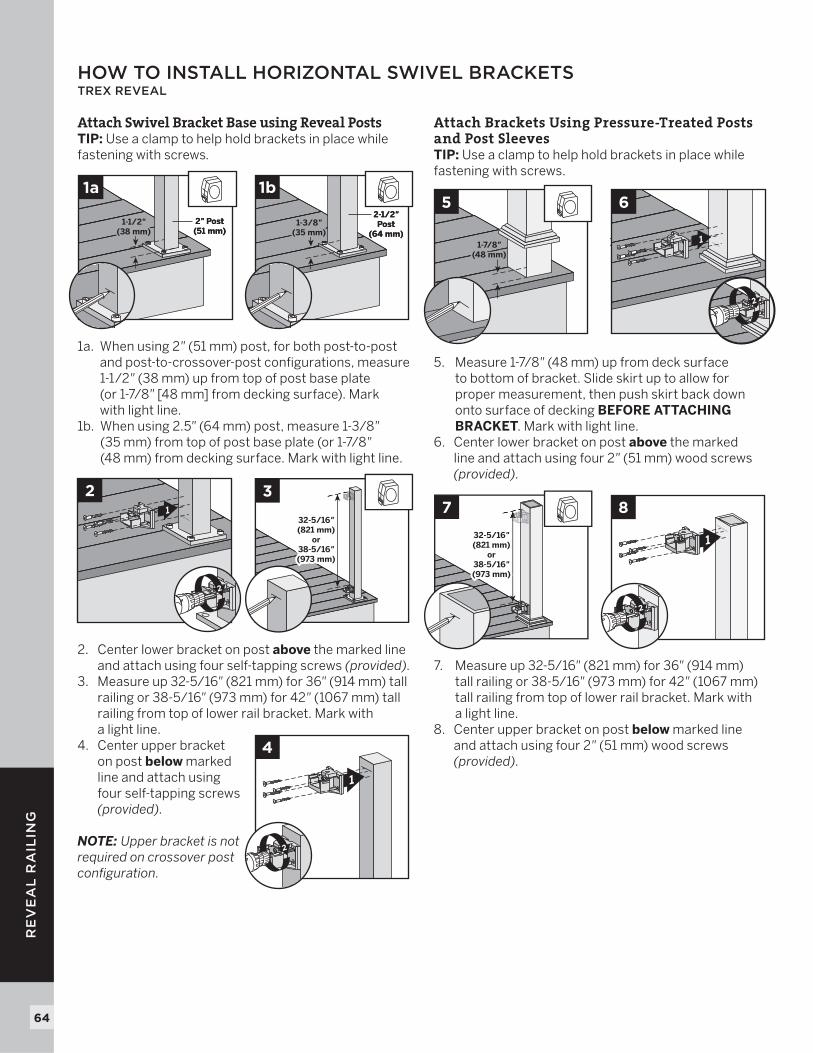
Attach Swivel Bracket Base using Reveal PostsTIP: Use a clamp to help hold brackets in place while fastening with screws.
1a. When using 2" (51 mm) post, for both post-to-post and post-to-crossover-post confi gurations, measure 1-1/2" (38 mm) up from top of post base plate (or 1-7/8" [48 mm] from decking surface). Mark with light line.
1b. When using 2.5" (64 mm) post, measure 1-3/8"(35 mm) from top of post base plate (or 1-7/8"(48 mm) from decking surface. Mark with light line.
2. Center lower bracket on post above the marked line and attach using four self-tapping screws (provided).
3. Measure up 32-5/16" (821 mm) for 36" (914 mm) tall railing or 38-5/16" (973 mm) for 42" (1067 mm) tall railing from top of lower rail bracket. Mark with a light line.
4. Center upper bracket on post below marked line and attach using four self-tapping screws (provided).
NOTE: Upper bracket is not required on crossover post confi guration.
Attach Brackets Using Pressure-Treated Posts and Post SleevesTIP: Use a clamp to help hold brackets in place while fastening with screws.
5. Measure 1-7/8" (48 mm) up from deck surface to bottom of bracket. Slide skirt up to allow for proper measurement, then push skirt back down onto surface of decking BEFORE ATTACHING BRACKET. Mark with light line.
6. Center lower bracket on post above the marked line and attach using four 2" (51 mm) wood screws (provided).
7. Measure up 32-5/16" (821 mm) for 36" (914 mm) tall railing or 38-5/16" (973 mm) for 42" (1067 mm) tall railing from top of lower rail bracket. Mark with a light line.
8. Center upper bracket on post below marked line and attach using four 2" (51 mm) wood screws (provided).
HOW TO INSTALL HORIZONTAL SWIVEL BRACKETSTREX REVEAL
1-1/2"(38 mm)
1-1/2"(38 mm)
2" Post(51 mm)2" Post(51 mm)
1a
32-5/16"(821 mm)
or38-5/16"(973 mm)
32-5/16"(821 mm)
or38-5/16"(973 mm)
3
1-7/8"(48 mm)
1-7/8"(48 mm)
5
32-5/16"(821 mm)
or38-5/16"(973 mm)
32-5/16"(821 mm)
or38-5/16"(973 mm)
7
1-3/8"(35 mm)1-3/8"
(35 mm)
2-1/2"Post
(64 mm)
2-1/2"Post
(64 mm)
1b
1
2
2
1
4
2
1
6
2
1
8
2
65
RE
VE
AL
RA
ILIN
G
HOW TO INSTALL HORIZONTAL SWIVEL RAILINGTREX REVEAL
NOTES:
» WHEN USING REVEAL HORIZONTAL SWIVEL BRACKETS BOTH BOTTOM AND TOP RAILS WILL NEED TO BE MEASURED AND CUT TO APPROPRIATE LENGTHS.
» HORIZONTAL SWIVEL BRACKETS CAN BE USED UP TO A 50º ANGLE FOR REVEAL RAILINGS.
» WHEN USING HORIZONTAL SWIVEL BRACKETS VERY IMPORTANT TO LAY OUT LOCATION AND ORIENTATION OF POSTS AND SWIVEL BRACKETS BEFORE INSTALLING SWIVEL BRACKETS.
» WHEN RAILINGS ARE CUT TO ODD SPANS, ALL SPANS GREATER THAN 5' (1.52 M) (EXAMPLE: 8' (2.44 M) SPAN CUT INTO ONE 5' (1.52 M) SPAN AND ONE 3' (0.91 M) SPAN) WOULD REQUIRE FOOT BLOCK UNDER 5' (1.52 M) SPAN SINCE SMALLER FIXED BALUSTER IS NO LONGER CENTERED).
How to Measure and Cut Bottom and Top Railings
1. With brackets in correct swivel location, measure distance from inside of bracket to inside of bracket. ENSURE THAT BEFORE CUTTING, BALUSTERS HOLES ON BOTH BOTTOM AND TOP RAIL LINE UP. ALSO MAKE SURE CENTER BALUSTER SLOT IS AS CLOSE TO THE MIDDLE OF THE SPAN AS POSSIBLE. In some cases due to odd railing spans, the center baluster may need to be offset in one or the other direction to ensure there is enough room at both post locations for balusters to be placed.
Cutting Bottom Rail and Bottom Rail Cover
2. Cut bottom rail to the measurement between the bottom swivel brackets
3. Slide rail insert out and cut 3/4" (19 mm) FROM EACH SIDE of insert, then slide back inside rail and center.
4. Mark and cut bottom rail cover 1-1/2"(38 mm) shorter than bottom rail.
1
Center slot for fixed baluster
2
Bottom rail
3
3/4"(19 mm)
3/4"(19 mm)3/4"
(19 mm)3/4"
(19 mm)
Bottom rail
1-1/2"(38 mm)
1-1/2"(38 mm)
4Bottom rail
Bottom rail cover
NOTE: Construction methods are always improving. Please refer to www.trex.com for the most up-to-date installation requirements.

66
RE
VE
AL
RA
ILIN
G
HOW TO INSTALL HORIZONTAL SWIVEL RAILING/CONTINUEDTREX REVEAL
Cutting Top RailOption 1:For Post-to-Post Configuration
5a. Cut top rail to the measurement between the top swivel brackets. For standard-post-to-standard-post confi gurations this would be same dimensions as that of the bottom rail.
Cutting Top RailOption 2:For Post-to-Crossover-Post Configuration
5b. When going from standard-post-to-crossover-post, measurement must be taken from inside of top horizontal swivel bracket to inside lip of crossover bracket (which is attached to top of crossover post).
Cutting Top Rail Insert and Cover
6. Slide rail insert out and cut 3/4" (19 mm) FROM EACH SIDE of insert, then slide back inside rail and center.
7. Mark and cut top rail cover same length as top rail for all top rail confi gurations.
8. Attaching Center Baluster to Bottom RailSee instructions on page 61.
9. Attaching Bottom Rail Cover and Bottom Rail to BracketsSee instructions on page 61.
10. Installing Remaining Balusters into Bottom RailSee instructions on page 61.
11. Attach Upper RailingsSee instructions on page 62.
12. Attachment of Bracket Covers, Skirts, and CapsSee instructions on page 63.
13. Attachment of Foot Block (Required ONLY for All Clear Span Applications Over 6' [1.83 m] )See instructions on page 67.
5a
1/4"(6 mm)
1/4"(6 mm)
1/4"(6 mm)
1/4"(6 mm)
KEYMarkCut
KEY
Top rail
Standard postStandard post
5b
Crossoverpost
Standardpost
6
3/4"(19 mm)
3/4"(19 mm)3/4"
(19 mm)3/4"
(19 mm)
Top rail
7
67
RE
VE
AL
RA
ILIN
G
HOW TO INSTALL FOOT BLOCKS – HORIZONTAL RAILING TREX REVEAL
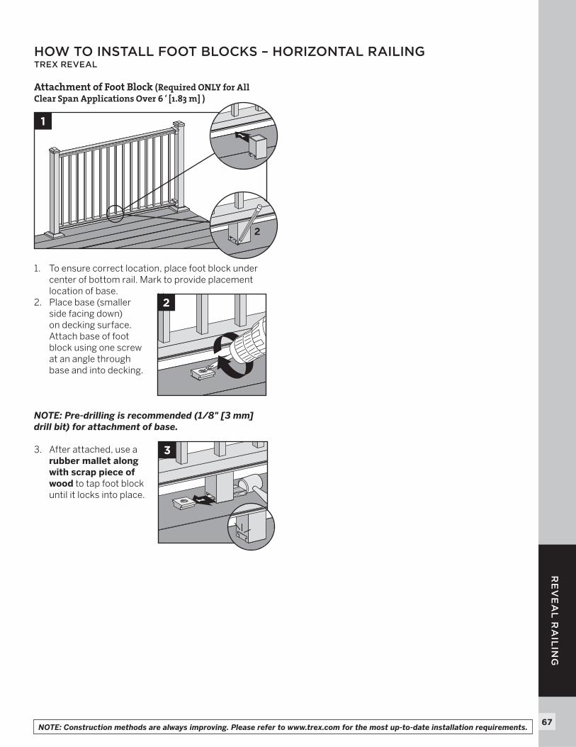
Attachment of Foot Block (Required ONLY for All Clear Span Applications Over 6' [1.83 m] )
1. To ensure correct location, place foot block under center of bottom rail. Mark to provide placement location of base.
2. Place base (smaller side facing down) on decking surface. Attach base of foot block using one screw at an angle through base and into decking.
NOTE: Pre-drilling is recommended (1/8" [3 mm] drill bit) for attachment of base.
3. After attached, use a rubber mallet along with scrap piece of wood to tap foot block until it locks into place.
1
2
1
2
1
3
NOTE: Construction methods are always improving. Please refer to www.trex.com for the most up-to-date installation requirements.
68
RE
VE
AL
RA
ILIN
G
BRACKET HARDWARE – STAIR APPLICATIONS (INCLUDING STAIR SWIVEL BRACKETS, STAIR CROSSOVER BRACKET, AND COMPOUND SWIVEL BRACKETS) TREX REVEAL
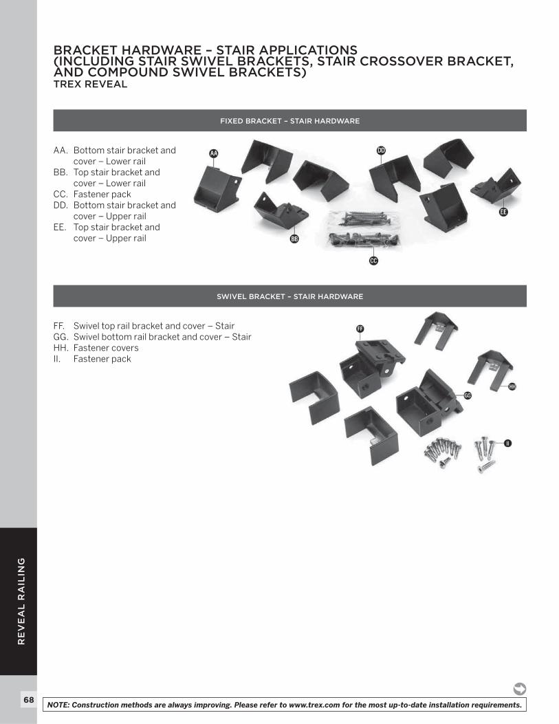
FIXED BRACKET – STAIR HARDWARE
AA. Bottom stair bracket and cover – Lower rail
BB. Top stair bracket and cover – Lower rail
CC. Fastener packDD. Bottom stair bracket and
cover – Upper railEE. Top stair bracket and
cover – Upper rail
SWIVEL BRACKET – STAIR HARDWARE
FF. Swivel top rail bracket and cover – StairGG. Swivel bottom rail bracket and cover – StairHH. Fastener coversII. Fastener pack
NOTE: Construction methods are always improving. Please refer to www.trex.com for the most up-to-date installation requirements.
69
RE
VE
AL
RA
ILIN
G
BRACKET HARDWARE – STAIR APPLICATIONS (INCLUDING STAIR SWIVEL BRACKETS, STAIR CROSSOVER BRACKET, AND COMPOUND SWIVEL BRACKETS)/CONTINUED TREX REVEAL
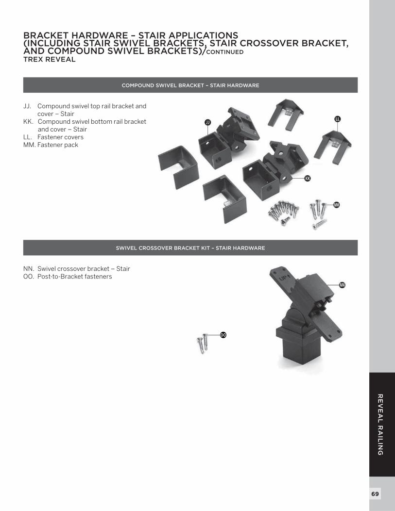
COMPOUND SWIVEL BRACKET – STAIR HARDWARE
JJ. Compound swivel top rail bracket and cover – Stair
KK. Compound swivel bottom rail bracket and cover – Stair
LL. Fastener coversMM. Fastener pack
SWIVEL CROSSOVER BRACKET KIT – STAIR HARDWARE
NN. Swivel crossover bracket – StairOO. Post-to-Bracket fasteners
OO
70
RE
VE
AL
RA
ILIN
G
IMPORTANT NOTES:» ALL REVEAL STAIR INSTALLATIONS REQUIRE THE
USE OF 53" (1346 MM) STAIR POST, MEASURED AND CUT TO APPROPRIATE LENGTH IF REQUIRED.
» IF CROSSOVER STAIR POST IS REQUIRED, USE STAIR POST (AGAIN CUT TO APPROPRIATE LENGTH IF REQUIRED) AND USE SWIVEL CROSSOVER BRACKET.
» REVEAL STAIR FIXED BRACKETS ARE DESIGNED TO WORK ONLY WITH STAIR SLOPES OF 32°-37°.
» FOR SMALLER (LESS THAN 32°) OR LARGER ANGLES (GREATER THAN 37°) USE THE REVEAL STAIR SWIVEL BRACKETS.
» REVEAL COMPOUND SWIVEL STAIR BRACKETS ARE DESIGNED FOR FLARED STAIR DESIGNS.
» IF INSTALLING STAIR RAILINGS AT EXACT SPAN LENGTHS OF 6' (1.83 M) OR 8' (2.44 M) AND USING POST TO POST CONFIGURATION, THE BOTTOM STAIR RAIL WILL NOT NEED TO BE CUT*, BUT THE TOP STAIR RAIL WILL NEED TO BE MEASURED (MAKING SURE BALUSTERS LINE UP VERTICALLY) AND CUT.
» IF INSTALLING STAIR RAILINGS AT EXACT SPAN LENGTHS OF 6' (1.83 M) OR 8' (2.44 M), AND USING CROSSOVER POST CONFIGURATION (SPANS FROM ONE CROSSOVER POST TO ANOTHER CROSSOVER POST), BOTH THE BOTTOM AND TOP STAIR RAILS WILL NOT NEED TO BE CUT* IF THE ANGLE IS APPROXIMATELY 34°.
» AT ALL FINAL END POST CONFIGURATIONS, TOP STAIR RAIL WILL NEED TO BE MEASURED (MAKING SURE BALUSTERS LINE UP VERTICALLY) AND CUT.
» FOR ODD SPAN LENGTHS, BOTH BOTTOM AND TOP STAIR RAILS WILL NEED TO BE MEASURED (MAKING SURE BALUSTERS LINE UP VERTICALLY) AND CUT. ALSO ENSURE THAT BALUSTERS ARE SPACED WITH EQUAL DISTANCE ON EACH SIDE OF THE POST.
* Rails that do not require cutting must be oriented in the correct direction to ensure balusters are spaced properly when installed in brackets. On both bottom and top stair railings, baluster hole closest to the end of the each stair rail is to be installed at the top of the stair section. Ensure that both bottom and top rails are correct and balusters line up vertically before installing.
Installing Standard Reveal Stair Posts, Reveal Stair Crossover Posts, or Pressure-Treated Post, Post Sleeves, and Skirts
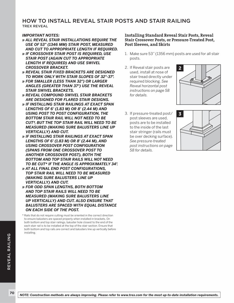
1. Make sure 53” (1356 mm) posts are used for all stair posts.
2. If Reveal stair posts are used, install at nose of stair tread directly under required blocking. See Reveal horizontal post instructions on page 58 for details.
3. If pressure-treated post/post sleeves are used, posts are to be installed to the inside of the last stair stringer (rails must be over decking surface). See pressure-treated post instructions on page 58 for details.
2
3
HOW TO INSTALL REVEAL STAIR POSTS AND STAIR RAILINGTREX REVEAL
NOTE: Construction methods are always improving. Please refer to www.trex.com for the most up-to-date installation requirements.
71
RE
VE
AL
RA
ILIN
G
ATTACHING STAIR BRACKETS (FIXED STAIR, STAIR SWIVEL, AND COMPOUND SWIVEL) TO REVEAL POSTS AND PRESSURE-TREATED POSTS AND POST SLEEVESTREX REVEAL
NOTES: » All Reveal fi xed stair brackets work ONLY with stair
slopes of 32°-37°.» Illustrations shown are representations when using
Reveal post, but same rules apply if using pressure-treated posts and post sleeves.
» Use a clamp to help hold stair brackets in place while fastening with screws.
» IMPORTANT NOTE: BEFORE ATTACHING ANY UPPER BRACKETS MAKE SURE PROPER RAILING HEIGHTS ARE ACHIEVED. RAILING HEIGHTS AND UPPER BRACKET HEIGHTS MAY NEED TO BE ADJUSTED, HOWEVER, DO NOT REDUCE HEIGHTS BASED ON YOUR RAILING CODE REQUIREMENTS. MEASURE CAREFULLY as dimension heights may need to be adjusted!
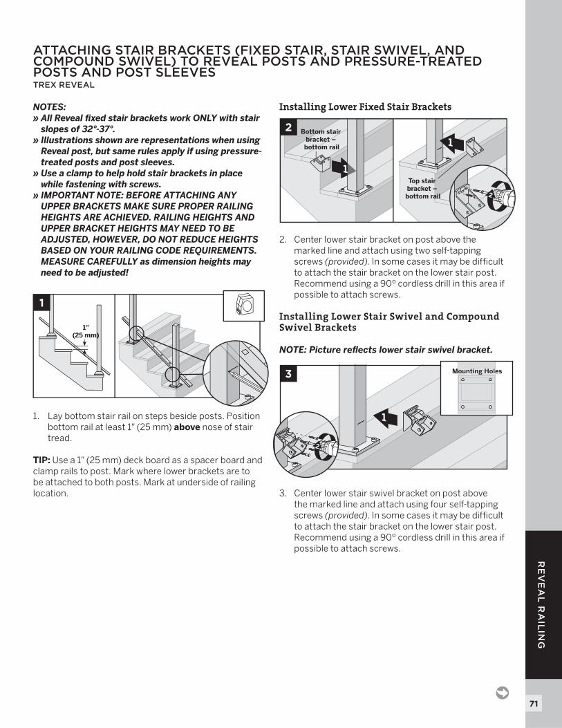
1. Lay bottom stair rail on steps beside posts. Position bottom rail at least 1" (25 mm) above nose of stair tread.
TIP: Use a 1" (25 mm) deck board as a spacer board and clamp rails to post. Mark where lower brackets are to be attached to both posts. Mark at underside of railing location.
Installing Lower Fixed Stair Brackets
2. Center lower stair bracket on post above the marked line and attach using two self-tapping screws (provided). In some cases it may be diffi cult to attach the stair bracket on the lower stair post. Recommend using a 90º cordless drill in this area if possible to attach screws.
Installing Lower Stair Swivel and Compound Swivel Brackets
NOTE: Picture refl ects lower stair swivel bracket.
3. Center lower stair swivel bracket on post above the marked line and attach using four self-tapping screws (provided). In some cases it may be diffi cult to attach the stair bracket on the lower stair post. Recommend using a 90º cordless drill in this area if possible to attach screws.
1"(25 mm)
1
2 Bottom stair bracket – bottom rail
Top stair bracket – bottom rail
1
1
2
1
3 Mounting HolesMounting Holes
2
72
RE
VE
AL
RA
ILIN
G
72
ATTACHING STAIR BRACKETS (FIXED STAIR, STAIR SWIVEL, AND COMPOUND SWIVEL) TO REVEAL POSTS AND PRESSURE-TREATED POSTS AND POST SLEEVES/CONTINUEDTREX REVEAL
Installing Upper Fixed Stair Brackets
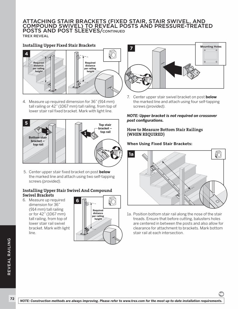
4. Measure up required dimension for 36” (914 mm) tall railing or 42” (1067 mm) tall railing, from top of lower stair rail fi xed bracket. Mark with light line.
5. Center upper stair fi xed bracket on post belowthe marked line and attach using two self-tapping screws (provided).
Installing Upper Stair Swivel And Compound Swivel Brackets6. Measure up required
dimension for 36”(914 mm) tall railing or for 42” (1067 mm) tall railing, from top of lower stair rail swivel bracket. Mark with light line.
7. Center upper stair swivel bracket on post belowthe marked line and attach using four self-tapping screws (provided).
NOTE: Upper bracket is not required on crossover post confi gurations.
How to Measure Bottom Stair Railings (WHEN REQUIRED)
When Using Fixed Stair Brackets:
1a. Position bottom stair rail along the nose of the stair treads. Ensure that before cutting, balusters holes are centered in between the posts and also allow for clearance for attachment to brackets. Mark bottom stair rail at each intersection.
Required distance
per railing height
Required distance
per railing height
Required distance
per railing height
Required distance
per railing height
47 Mounting HolesMounting Holes
2
5
Bottom stair bracket –
top rail
Top stair bracket –
top rail1 1
2 1a
Required distance
per railing height
Required distance
per railing height
6
NOTE: Construction methods are always improving. Please refer to www.trex.com for the most up-to-date installation requirements.
73
RE
VE
AL
RA
ILIN
G
When using Stair Swivel and Compound Swivel Brackets:
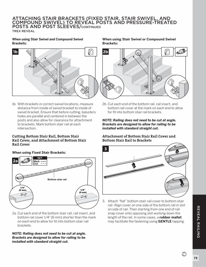
1b. With brackets in correct swivel locations, measure distance from inside of swivel bracket to inside of swivel bracket. Ensure that before cutting, balusters holes are parallel and centered in between the posts and also allow for clearance for attachment to brackets. Mark bottom stair rail at each intersection.
Cutting Bottom Stair Rail, Bottom Stair Rail Cover, and Attachment of Bottom StairRail Cover
When using Fixed Stair Brackets:
2a. Cut each end of the bottom stair rail, rail insert, and bottom rail cover 1/4" (6 mm) shorter than the mark on each end to allow for fi t into bottom stair rail brackets.
NOTE: Railing does not need to be cut at angle. Brackets are designed to allow for railing to be installed with standard straight cut.
When using Stair Swivel or Compound Swivel Brackets:
2b. Cut each end of the bottom rail, rail insert, and bottom rail cover at the mark on each end to allow for fi t into bottom stair rail brackets.
NOTE: Railing does not need to be cut at angle. Brackets are designed to allow for railing to be installed with standard straight cut.
Attachment of Bottom Stair Rail Cover and Bottom Stair Rail to Brackets
3. Attach “fl at” bottom stair rail cover to bottom stair rail. Align cover on one side of the bottom rail in slot on side of rail. Then starting from one end of rail snap cover onto opposing slot working down the length of the rail. In some cases, a rubber malletmay facilitate the fastening using GENTLE tapping.
ATTACHING STAIR BRACKETS (FIXED STAIR, STAIR SWIVEL, AND COMPOUND SWIVEL) TO REVEAL POSTS AND PRESSURE-TREATED POSTS AND POST SLEEVES/CONTINUEDTREX REVEAL
2a
1/4"(6 mm)
1/4"(6 mm)
1/4"(6 mm)
1/4"(6 mm)
KEYMarkCut
KEY
Bottom stair rail
1b 2b
1
3
3
2
74
RE
VE
AL
RA
ILIN
G
74
ATTACHING STAIR BRACKETS (FIXED STAIR, STAIR SWIVEL, AND COMPOUND SWIVEL) TO REVEAL POSTS AND PRESSURE-TREATED POSTS AND POST SLEEVES/CONTINUEDTREX REVEAL
4. Set bottom stair rail into bottom stair rail brackets. Attach bottom stair rail to bottom stair bracket using two self-tapping screws (provided) on each side of bracket.
How to Measure Top Stair Railings (WHEN REQUIRED):
IMPORTANT NOTE: BEFORE CUTTING ANY TOP RAILS MAKE SURE THAT WHEN MEASURING ALL BALUSTER HOLES LINE UP PARALLEL!
When Using Fixed Stair Brackets:5a. Place two balusters
into lower rail at each end closest to post.
5b. Position top rail onto balusters (position to side of post) and ENSURE that balusters are parallel with post. Mark top stair rail at each intersection.
When using Stair Swivel and Compound Swivel Brackets: 5c. Place two balusters into
lower rail at each end closest to post.
5d. Position top rail onto balusters (position to side of post) and ENSURE that balusters are parallel with post. With brackets in correct swivel location, measure distance from inside of swivel bracket to inside of swivel bracket. Mark top stair rail at each intersection.
1
1
4
2
5a
5c
5b
5d
NOTE: Construction methods are always improving. Please refer to www.trex.com for the most up-to-date installation requirements.
75
RE
VE
AL
RA
ILIN
G
Attaching Stair Crossover Swivel Bracket to Post
6. Insert stair crossover swivel bracket into post.
NOTE: Keep the bracket cover on when inserting this into post, this will cover the screw attachment area.
7. Determine location/height of the stair crossover swivel bracket by aligning the angle of this with the fi xed brackets (or compound swivel brackets) already installed.
8. Once location/height is determined, center and pre-drill two holes (using a drill bit slightly smaller than that of self-tapping screw diameter) on opposite sides of post, approx. 1/4" (6 mm) from top of post. Drill through the post and into the stair crossover swivel bracket on each side.
9. Attach stair crossover swivel bracket to post with two self-tapping screws (provided). Slide cover over post to hide screws.
ATTACHING STAIR BRACKETS (FIXED STAIR, STAIR SWIVEL, AND COMPOUND SWIVEL) TO REVEAL POSTS AND PRESSURE-TREATED POSTS AND POST SLEEVES/CONTINUEDTREX REVEAL
Bracketcover
6
7 X°
8
1/4"(6 mm)
1/4"(6 mm)
9
1
2
76
RE
VE
AL
RA
ILIN
G
76
ATTACHING STAIR BRACKETS (FIXED STAIR, STAIR SWIVEL, AND COMPOUND SWIVEL) TO REVEAL POSTS AND PRESSURE-TREATED POSTS AND POST SLEEVES/CONTINUEDTREX REVEAL
Cutting Top Stair Rail and Rail InsertOption 1:For Stair-Post-to-Stair-Post Configuration
When Using Fixed Stair Brackets:
10a. Cut each end of top stair rail along with rail insert 1/4" (6 mm) shorter than mark to allow for fi t into top stair rail bracket.
NOTE: Railing does not need to be cut at angle. Brackets are designed to allow for railing to be installed with standard straight cut.
When using Upper Stair Swivel and Compound Swivel Brackets:
10b. Cut top rail along with rail insert to the measurement between the top stair swivel brackets. For standard-post-to-standard-post confi gurations, this would be same dimensions as that of the bottom stair rail.
Cutting Top Stair Rail and InsertOption 2: For Stair-Post-to-Stair-Crossover-Post Configuration
When Using Fixed Stair Brackets:
11a. Top stair rail along with rail insert must be cut differently on each side of the rail. Railing side that attaches to standard post should be cut 1/4"(6 mm) shorter than the mark to allow for fi t into top rail bracket. Railing side that attaches to the crossover post should be cut directly on the mark to allow for fi t into the crossover post bracket.
When using Upper Stair Swivel and Stair Crossover Swivel Brackets:
11b. When going from standard-stair-post-to-stair-crossover-post, measurement must be taken from inside of top horizontal stair swivel bracket to inside lip of stair crossover bracket (crossover post will need to be modifi ed to have swivel crossover bracket installed).
11a
1/4"(6 mm)
1/4"(6 mm)
KEYMarkCut
KEY
Top stair rail
Crossover postStandard post
11b
Crossoverpost
StandardpostStandardpost
10b
Standardpost
StandardpostStandardpost
10a
1/4"(6 mm)
1/4"(6 mm)
1/4"(6 mm)
1/4"(6 mm)
KEYMarkCut
KEY
Top stair rail
Standard postStandard post
NOTE: Construction methods are always improving. Please refer to www.trex.com for the most up-to-date installation requirements.
77
RE
VE
AL
RA
ILIN
G
ATTACHING STAIR BRACKETS (FIXED STAIR, STAIR SWIVEL, AND COMPOUND SWIVEL) TO REVEAL POSTS AND PRESSURE-TREATED POSTS AND POST SLEEVES/CONTINUEDTREX REVEAL
Cutting Top Stair Rail and Rail InsertOption 3:For Stair-Crossover-Post-to-Stair-Crossover-Post Configuration
12a. Cut each end of the top stair rail along with rail insert on the mark line to allow for fi t into the crossover post bracket on each side.
Cutting Top Stair Rail Cover, and Attachment of Top Stair Rail Cover13. Mark and cut top rail
cover same length as top rail for all top rail confi gurations.
14. Attach “crowned” upper stair rail cover to upper stair rail by aligning cover on one side of rail. Then starting from one end of stair rail, snap cover onto opposing slot working down length of stair rail. A rubber mallet may facilitate the fastening using GENTLE tapping.
Installing Balusters into Bottom Stair Rail15. Place balusters into
holes in lower stair rail by snapping fully into place. In some cases, a rubber mallet may facilitate the fastening using GENTLE tapping.
1
14
3
2
15
13
12aKEYMarkCut
KEY
Top stair rail
Crossover post Crossover post
78
RE
VE
AL
RA
ILIN
G
ATTACHING STAIR BRACKETS (FIXED STAIR, STAIR SWIVEL, AND COMPOUND SWIVEL) TO REVEAL POSTS AND PRESSURE-TREATED POSTS AND POST SLEEVES/CONTINUEDTREX REVEAL
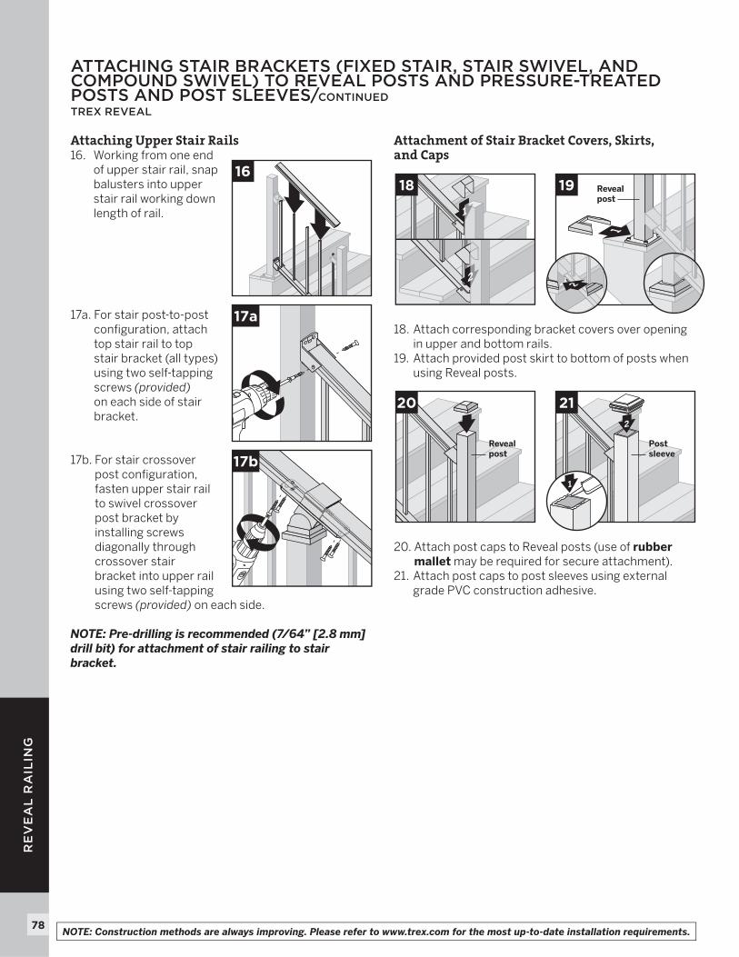
Attaching Upper Stair Rails16. Working from one end
of upper stair rail, snap balusters into upper stair rail working down length of rail.
17a. For stair post-to-post confi guration, attach top stair rail to top stair bracket (all types) using two self-tapping screws (provided)on each side of stair bracket.
17b. For stair crossover post confi guration, fasten upper stair rail to swivel crossover post bracket by installing screws diagonally through crossover stair bracket into upper rail using two self-tapping screws (provided) on each side.
NOTE: Pre-drilling is recommended (7/64” [2.8 mm] drill bit) for attachment of stair railing to stair bracket.
Attachment of Stair Bracket Covers, Skirts, and Caps
18. Attach corresponding bracket covers over opening in upper and bottom rails.
19. Attach provided post skirt to bottom of posts when using Reveal posts.
20. Attach post caps to Reveal posts (use of rubber mallet may be required for secure attachment).
21. Attach post caps to post sleeves using external grade PVC construction adhesive.
20
Revealpost
2
21
Postsleeve
3
1
17a
17b
1
2
18
1
19 Revealpost
2
16
NOTE: Construction methods are always improving. Please refer to www.trex.com for the most up-to-date installation requirements.
79
RE
VE
AL
RA
ILIN
G
INSTALLING ALUMINUM GATETREX ALUMINUM
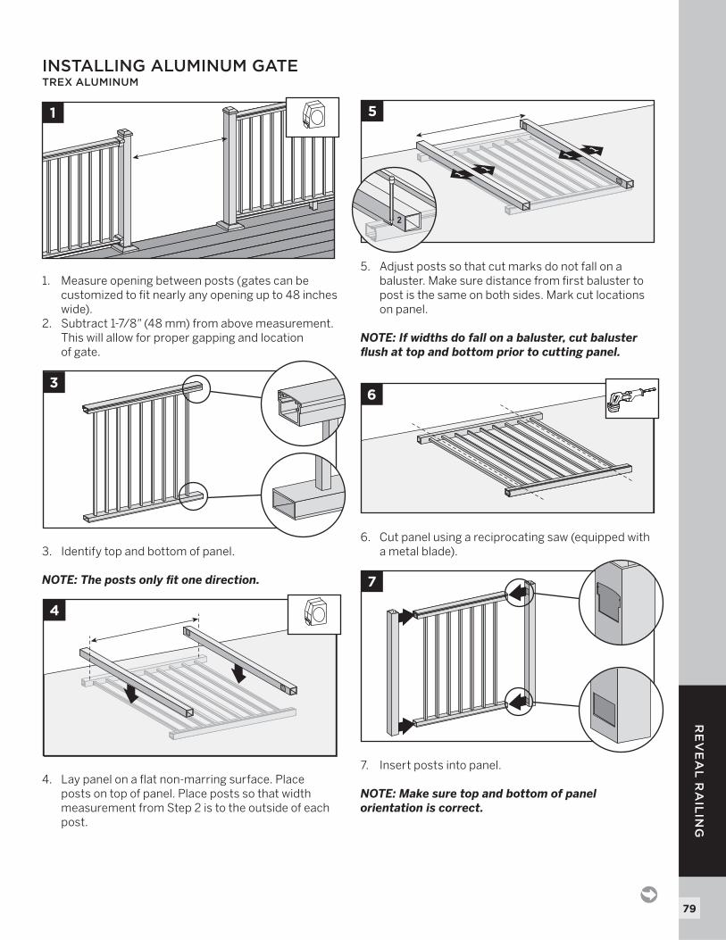
1. Measure opening between posts (gates can be customized to fit nearly any opening up to 48 inches wide).
2. Subtract 1-7/8" (48 mm) from above measurement. This will allow for proper gapping and location of gate.
3. Identify top and bottom of panel.
NOTE: The posts only fit one direction.
4. Lay panel on a flat non-marring surface. Place posts on top of panel. Place posts so that width measurement from Step 2 is to the outside of each post.
5. Adjust posts so that cut marks do not fall on a baluster. Make sure distance from first baluster to post is the same on both sides. Mark cut locations on panel.
NOTE: If widths do fall on a baluster, cut baluster flush at top and bottom prior to cutting panel.
6. Cut panel using a reciprocating saw (equipped with a metal blade).
7. Insert posts into panel.
NOTE: Make sure top and bottom of panel orientation is correct.
1
3
1
1
1
11
5
2
4
16
7
80
RE
VE
AL
RA
ILIN
G
NOTE: Construction methods are always improving. Please refer to www.trex.com for the most up-to-date installation requirements.
8. Secure posts to panel with four #8-18 short self-tapping screws (provided) in each location.
9. Attach shorter side of hinge to the gate.
NOTE: Refer to instructions included in hardware package. Be sure to use correct fasteners for aluminum. See chart below.
NOTE: Use of non-Trex hardware is not recommended and could result in serious injury or death.
10. Place gate in opening on blocks. Sweep between bottom of gate and top of deck cannot exceed 4" (102 mm) per IRC/IBC code regulations. Ensure bottom gate posts will be high enough to clear skirts on bottom of deck posts.
11. Make sure posts are plumb and gate is level. Attach longer side of hinges to post using appropriate hardware for type of post installed. Install hinge cover.
NOTE: Both wood and aluminum screws are included in hardware kit. (Refer to chart underStep 9.)
12. After determining location and height of hinge and hasp, install per instructions included with hardware kit.
13. Ensure proper operation of gate. Hinge tension is adjustable (check hardware kit instructions for more detail).
14. After gate installation, place blocks under gate for support. Use a rubber mallet to install cap onto gate post. Repeat for other gate post cap. Snap all hinge covers into place.
INSTALLING ALUMINUM GATE/CONTINUEDTREX ALUMINUM
8
1
1
9
2
10
4" max(102 mm)
4" max(102 mm)
11
2
1
114
2
MINIMUM FASTENER SIZE
SCREWS
Type Length No.
Wood Screw
2-1/2" (64 mm) #9
Metal Screw
2" (51 mm) #8-18
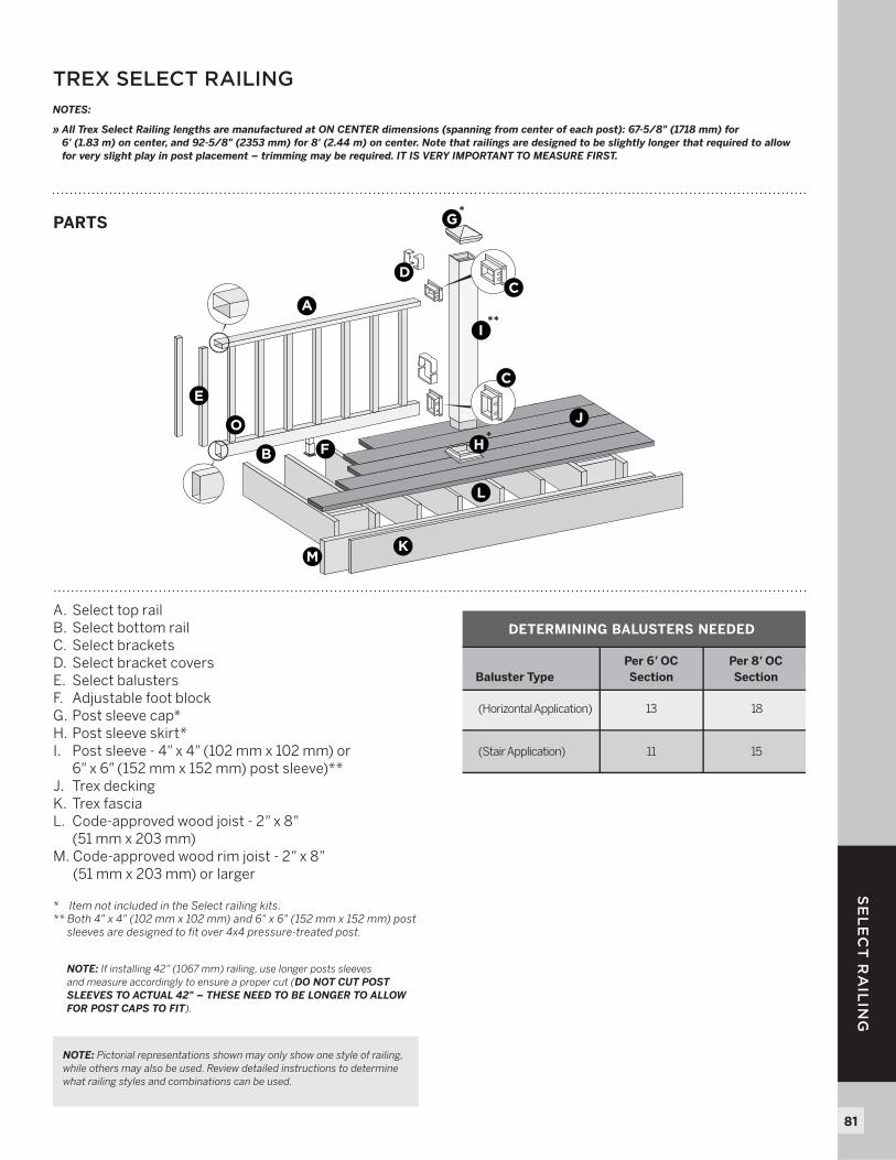
81
SE
LE
CT
RA
ILIN
G
TREX SELECT RAILING
PARTS
A. Select top railB. Select bottom railC. Select bracketsD. Select bracket coversE. Select balustersF. Adjustable foot blockG. Post sleeve cap*H. Post sleeve skirt*I. Post sleeve - 4" x 4" (102 mm x 102 mm) or
6" x 6" (152 mm x 152 mm) post sleeve)**J. Trex deckingK. Trex fasciaL. Code-approved wood joist - 2" x 8"
(51 mm x 203 mm)M. Code-approved wood rim joist - 2" x 8"
(51 mm x 203 mm) or larger
* Item not included in the Select railing kits.** Both 4" x 4" (102 mm x 102 mm) and 6" x 6" (152 mm x 152 mm) post
sleeves are designed to fit over 4x4 pressure-treated post.
A
B
C
C
D
E
G*
H*
I**
J
K
L
M
F
O
DETERMINING BALUSTERS NEEDED
Per 6' OCSectionBaluster Type
Per 8' OCSection
(Horizontal Application) 13 18
(Stair Application) 11 15
NOTE: Pictorial representations shown may only show one style of railing, while others may also be used. Review detailed instructions to determine what railing styles and combinations can be used.
NOTE: If installing 42" (1067 mm) railing, use longer posts sleeves and measure accordingly to ensure a proper cut (DO NOT CUT POST SLEEVES TO ACTUAL 42" – THESE NEED TO BE LONGER TO ALLOW FOR POST CAPS TO FIT).
NOTES:
» All Trex Select Railing lengths are manufactured at ON CENTER dimensions (spanning from center of each post): 67-5/8" (1718 mm) for 6' (1.83 m) on center, and 92-5/8" (2353 mm) for 8' (2.44 m) on center. Note that railings are designed to be slightly longer that required to allow for very slight play in post placement – trimming may be required. IT IS VERY IMPORTANT TO MEASURE FIRST.
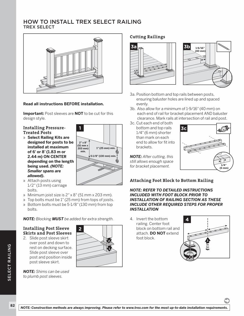
82
SE
LE
CT
RA
ILIN
G
HOW TO INSTALL TREX SELECT RAILINGTREX SELECT
Read all instructions BEFORE installation.
Important: Post sleeves are NOT to be cut for this design style.
Installing Pressure-Treated Posts» Select Railing Kits are
designed for posts to be installed at maximum of 6' or 8' (1.83 m or 2.44 m) ON CENTER depending on the length being used. (NOTE: Smaller spans are allowed).
» Attach posts using 1/2" (13 mm) carriage bolts.
» Minimum joist size is 2" x 8" (51 mm x 203 mm).» Top bolts must be 1" (25 mm) from tops of joists.» Bottom bolts must be 5-1/8 " (130 mm) from top
bolts.
NOTE: Blocking MUST be added for extra strength.
Installing Post Sleeve Skirts and Post Sleeves 2. Slide post sleeve skirt
over post and down to rest on decking surface. Slide post sleeve over post and position inside post sleeve skirt.
NOTE: Shims can be used to plumb post sleeves.
Cutting Railings
3a. Position bottom and top rails between posts, ensuring baluster holes are lined up and spaced evenly.
3b. Also allow for a minimum of 1-9/16" (40 mm) on each end of rail for bracket placement AND baluster clearance. Mark rails at intersection of rail and post.
3c. Cut each end of both bottom and top rails 1/4" (6 mm) shorter than mark on each end to allow for fi t into brackets.
NOTE: After cutting, this still allows enough space for bracket placement.
Attaching Foot Block to Bottom Railing
NOTE: REFER TO DETAILED INSTRUCTIONS INCLUDED WITH FOOT BLOCK PRIOR TO INSTALLATION OF RAILING SECTION AS THESE INCLUDE OTHER REQUIRED STEPS FOR PROPER INSTALLATION
4. Invert the bottom railing. Center foot block on bottom rail and attach. DO NOT extend foot block.
1
2
2
1
5-1/8" (130 mm) min.
2" x 8"(51 mm x 203 mm)
min.1" (25 mm) min.
1
4
2
3a
3c
1/4" (6 mm)
1-9/16" (40 mm)
3b
NOTE: Construction methods are always improving. Please refer to www.trex.com for the most up-to-date installation requirements.
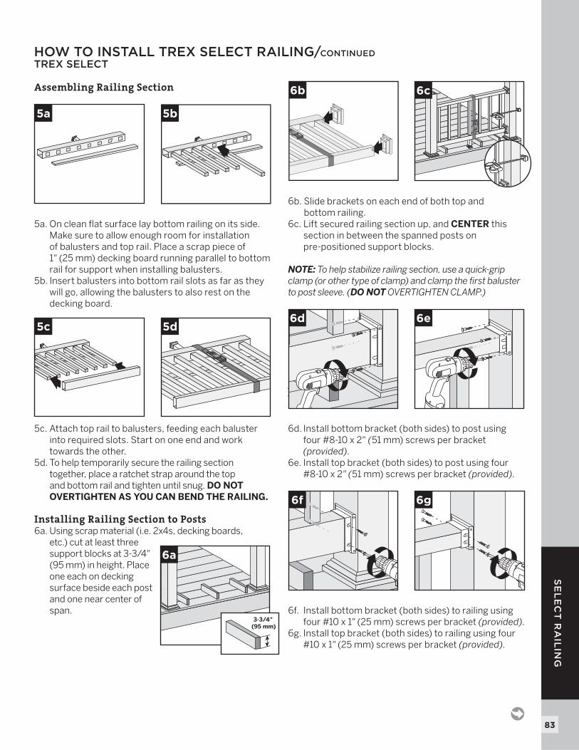
83
SE
LE
CT
RA
ILIN
G
HOW TO INSTALL TREX SELECT RAILING/CONTINUEDTREX SELECT
Assembling Railing Section
5a. On clean fl at surface lay bottom railing on its side. Make sure to allow enough room for installation of balusters and top rail. Place a scrap piece of 1" (25 mm) decking board running parallel to bottom rail for support when installing balusters.
5b. Insert balusters into bottom rail slots as far as they will go, allowing the balusters to also rest on the decking board.
5c. Attach top rail to balusters, feeding each baluster into required slots. Start on one end and work towards the other.
5d. To help temporarily secure the railing section together, place a ratchet strap around the top and bottom rail and tighten until snug. DO NOT OVERTIGHTEN AS YOU CAN BEND THE RAILING.
Installing Railing Section to Posts6a. Using scrap material (i.e. 2x4s, decking boards,
etc.) cut at least three support blocks at 3-3/4"(95 mm) in height. Place one each on decking surface beside each post and one near center of span.
6b. Slide brackets on each end of both top and bottom railing.
6c. Lift secured railing section up, and CENTER this section in between the spanned posts on pre-positioned support blocks.
NOTE: To help stabilize railing section, use a quick-grip clamp (or other type of clamp) and clamp the fi rst baluster to post sleeve. (DO NOT OVERTIGHTEN CLAMP.)
6d. Install bottom bracket (both sides) to post using four #8-10 x 2" (51 mm) screws per bracket (provided).
6e. Install top bracket (both sides) to post using four #8-10 x 2" (51 mm) screws per bracket (provided).
6f. Install bottom bracket (both sides) to railing using four #10 x 1" (25 mm) screws per bracket (provided).
6g. Install top bracket (both sides) to railing using four #10 x 1" (25 mm) screws per bracket (provided).
6d 6e
6a
3-3/4" (95 mm)
6b 6c
5c 5d
5a 5b
6f 6g
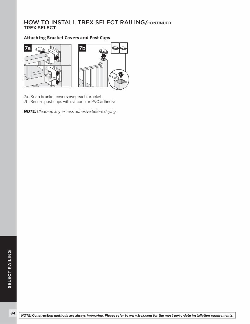
84
SE
LE
CT
RA
ILIN
G
Attaching Bracket Covers and Post Caps
7a. Snap bracket covers over each bracket.7b. Secure post caps with silicone or PVC adhesive.
NOTE: Clean-up any excess adhesive before drying.
7a
2
7b
1
HOW TO INSTALL TREX SELECT RAILING/CONTINUEDTREX SELECT
NOTE: Construction methods are always improving. Please refer to www.trex.com for the most up-to-date installation requirements.
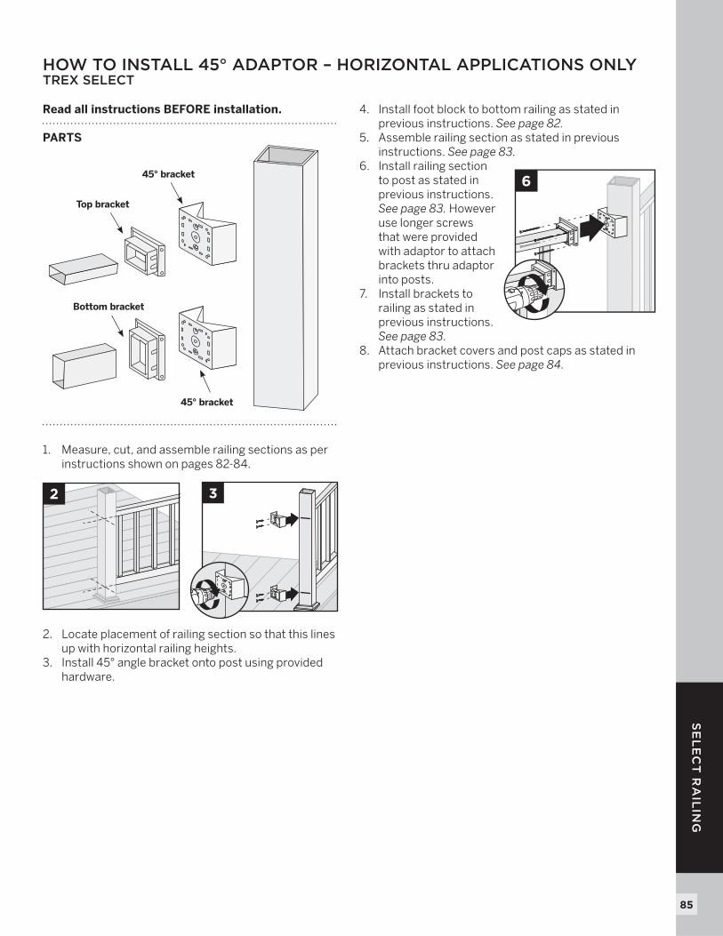
85
SE
LE
CT
RA
ILIN
G
HOW TO INSTALL 45° ADAPTOR – HORIZONTAL APPLICATIONS ONLYTREX SELECT
Read all instructions BEFORE installation.
PARTS
1. Measure, cut, and assemble railing sections as per instructions shown on pages 82-84.
2. Locate placement of railing section so that this lines up with horizontal railing heights.
3. Install 45° angle bracket onto post using provided hardware.
4. Install foot block to bottom railing as stated in previous instructions. See page 82.
5. Assemble railing section as stated in previous instructions. See page 83.
6. Install railing section to post as stated in previous instructions. See page 83. However use longer screws that were provided with adaptor to attach brackets thru adaptor into posts.
7. Install brackets to railing as stated in previous instructions. See page 83.
8. Attach bracket covers and post caps as stated in previous instructions. See page 84.
2
Top bracket
45° bracket
45° bracket
Bottom bracket
3
6
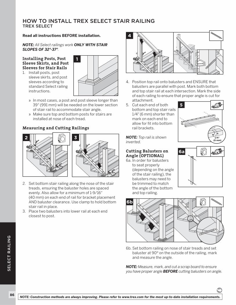
86
SE
LE
CT
RA
ILIN
G
Read all instructions BEFORE installation.
NOTE: All Select railings work ONLY WITH STAIR SLOPES OF 32°-37°.
Installing Posts, Post Sleeve Skirts, and Post Sleeves for Stair Rails 1. Install posts, post
sleeve skirts, and post sleeves according to standard Select railing instructions. » In most cases, a post and post sleeve longer than
39" (991 mm) will be needed on the lower section of stair rail to accommodate stair angle.
» Make sure top and bottom posts for stairs are installed at nose of each tread.
Measuring and Cutting Railings
2. Set bottom stair railing along the nose of the stair treads, ensuring the baluster holes are spaced evenly. Also allow for a minimum of 1-9/16" (40 mm) on each end of rail for bracket placement AND baluster clearance. Use clamp to hold bottom stair rail in place.
3. Place two balusters into lower rail at each end closest to post.
4. Position top rail onto balusters and ENSURE that balusters are parallel with post. Mark both bottom and top stair rail at each intersection. Mark the side of each railing to ensure that proper angle is cut for attachment.
5. Cut each end of both bottom and top stair rails 1/4" (6 mm) shorter than mark on each end to allow for fit into bottom rail brackets.
NOTE: Top rail is shown inverted.
Cutting Balusters on Angle (OPTIONAL)6a. In order for balusters
to seat properly (depending on the angle of the stair railing), the balusters may need to be trimmed to match the angle of the bottom and top railing.
6b. Set bottom railing on nose of stair treads and set baluster at 90º on the outside of the railing, mark and measure the angle.
NOTE: Measure, mark, and cut a scrap board to ensure you have proper angle BEFORE cutting balusters on angle.
1
6a
5
1/4" (6 mm)
6b
2 3
HOW TO INSTALL TREX SELECT STAIR RAILING TREX SELECT
4
NOTE: Construction methods are always improving. Please refer to www.trex.com for the most up-to-date installation requirements.
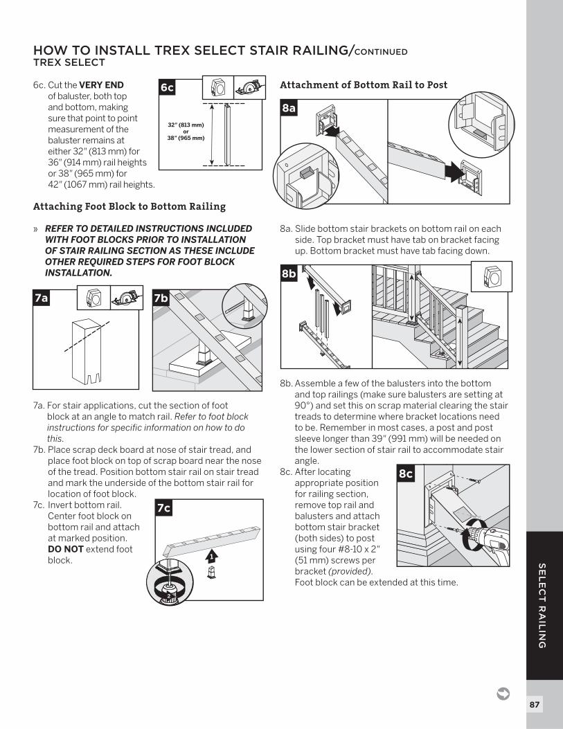
87
SE
LE
CT
RA
ILIN
G
6c. Cut the VERY ENDof baluster, both top and bottom, making sure that point to point measurement of the baluster remains at either 32" (813 mm) for 36" (914 mm) rail heights or 38" (965 mm) for 42" (1067 mm) rail heights.
Attaching Foot Block to Bottom Railing
» REFER TO DETAILED INSTRUCTIONS INCLUDED WITH FOOT BLOCKS PRIOR TO INSTALLATION OF STAIR RAILING SECTION AS THESE INCLUDE OTHER REQUIRED STEPS FOR FOOT BLOCK INSTALLATION.
7a. For stair applications, cut the section of foot block at an angle to match rail. Refer to foot block instructions for specifi c information on how to do this.
7b. Place scrap deck board at nose of stair tread, and place foot block on top of scrap board near the nose of the tread. Position bottom stair rail on stair tread and mark the underside of the bottom stair rail for location of foot block.
7c. Invert bottom rail. Center foot block on bottom rail and attach at marked position. DO NOT extend foot block.
Attachment of Bottom Rail to Post
8a. Slide bottom stair brackets on bottom rail on each side. Top bracket must have tab on bracket facing up. Bottom bracket must have tab facing down.
8b. Assemble a few of the balusters into the bottom and top railings (make sure balusters are setting at 90°) and set this on scrap material clearing the stair treads to determine where bracket locations need to be. Remember in most cases, a post and post sleeve longer than 39" (991 mm) will be needed on the lower section of stair rail to accommodate stair angle.
8c. After locating appropriate position for railing section, remove top rail and balusters and attach bottom stair bracket (both sides) to post using four #8-10 x 2"(51 mm) screws per bracket (provided). Foot block can be extended at this time.
7a 7b
1
7c
2
8c
8a
8b
HOW TO INSTALL TREX SELECT STAIR RAILING/CONTINUEDTREX SELECT
32" (813 mm)or
38" (965 mm)
6c
88
SE
LE
CT
RA
ILIN
G
Install Balusters9. Slide balusters into
bottom rail.
Attachment of Top Rail to Post
10a. Slide top stair brackets on top rail on each side. Top bracket must have tab on bracket facing up. Bottom bracket must have tab facing down.
10b. Place top rail onto balusters, allowing the top rail to rest on the surface of the balusters.
10c. Attach top stair bracket (both sides) to post using four #8-10 x 2" (51 mm) screws per bracket (provided).
Attachment of Bottom and Top Brackets to Rails
11a. Install bottom stair bracket (both sides) to railing using four #10 x 1" (25 mm) screws per bracket (provided).
11b. Install top stair bracket (both sides) to railing using four #10 x 1" (25 mm) screws per bracket (provided).
Attaching Bracket Covers and Post Caps
12a. Snap bracket covers over top rail bracket.12b. Snap bracket covers over bottom rail bracket.12c. Secure post caps
with silicone or PVC adhesive.
NOTE: Clean-up any excess adhesive before drying.
10a
11a
10b
11b
10c
12a 12b
2
12c
1
HOW TO INSTALL TREX SELECT STAIR RAILING/CONTINUEDTREX SELECT
9
NOTE: Construction methods are always improving. Please refer to www.trex.com for the most up-to-date installation requirements.
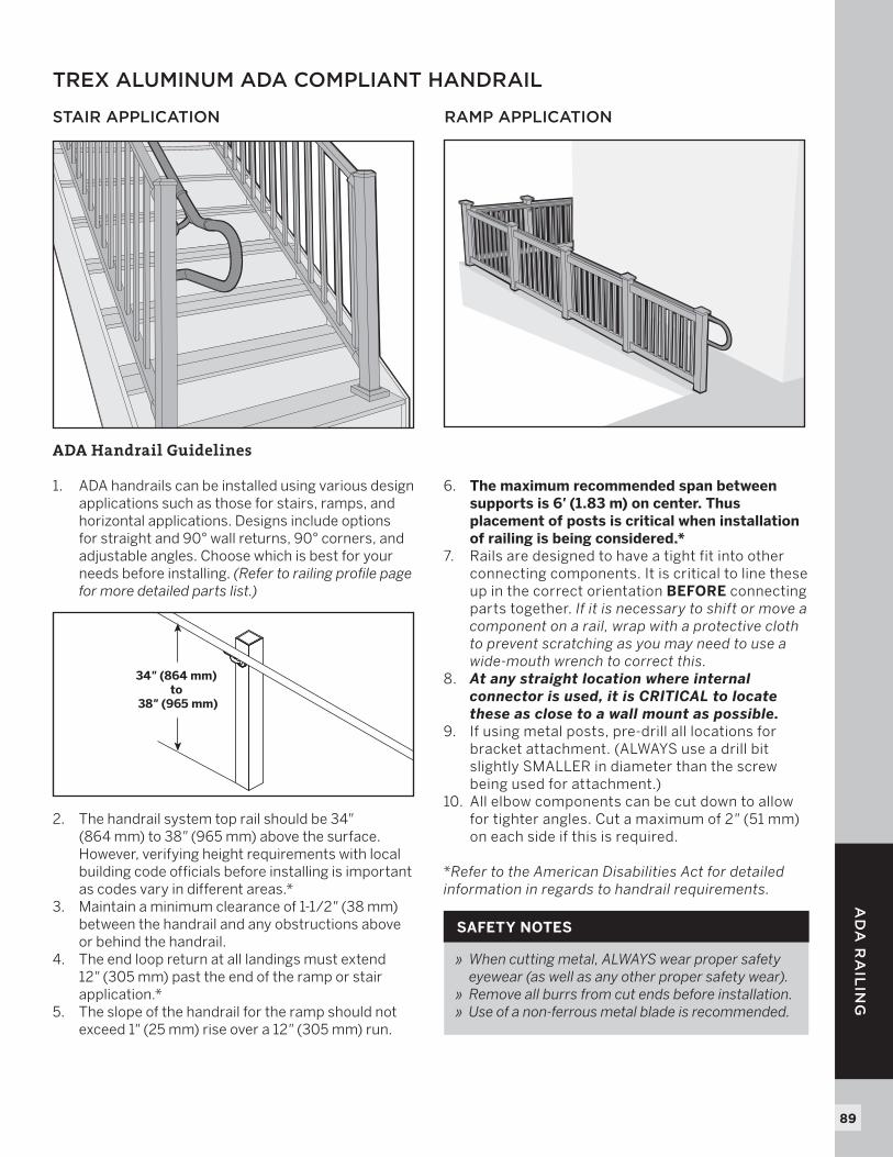
89
RA
ILIN
G
89
AD
A R
AIL
ING
TREX ALUMINUM ADA COMPLIANT HANDRAIL
STAIR APPLICATION
ADA Handrail Guidelines
1. ADA handrails can be installed using various design applications such as those for stairs, ramps, and horizontal applications. Designs include options for straight and 90° wall returns, 90° corners, and adjustable angles. Choose which is best for your needs before installing. (Refer to railing profile page for more detailed parts list.)
2. The handrail system top rail should be 34" (864 mm) to 38" (965 mm) above the surface. However, verifying height requirements with local building code officials before installing is important as codes vary in different areas.*
3. Maintain a minimum clearance of 1-1/2" (38 mm) between the handrail and any obstructions above or behind the handrail.
4. The end loop return at all landings must extend 12" (305 mm) past the end of the ramp or stair application.*
5. The slope of the handrail for the ramp should not exceed 1" (25 mm) rise over a 12" (305 mm) run.
6. The maximum recommended span between supports is 6' (1.83 m) on center. Thus placement of posts is critical when installation of railing is being considered.*
7. Rails are designed to have a tight fit into other connecting components. It is critical to line these up in the correct orientation BEFORE connecting parts together. If it is necessary to shift or move a component on a rail, wrap with a protective cloth to prevent scratching as you may need to use a wide-mouth wrench to correct this.
8. At any straight location where internal connector is used, it is CRITICAL to locate these as close to a wall mount as possible.
9. If using metal posts, pre-drill all locations for bracket attachment. (ALWAYS use a drill bit slightly SMALLER in diameter than the screw being used for attachment.)
10. All elbow components can be cut down to allow for tighter angles. Cut a maximum of 2" (51 mm)on each side if this is required.
*Refer to the American Disabilities Act for detailed information in regards to handrail requirements.
34" (864 mm) to
38" (965 mm)
RAMP APPLICATION
» When cutting metal, ALWAYS wear proper safety eyewear (as well as any other proper safety wear).
» Remove all burrs from cut ends before installation.» Use of a non-ferrous metal blade is recommended.
SAFETY NOTES
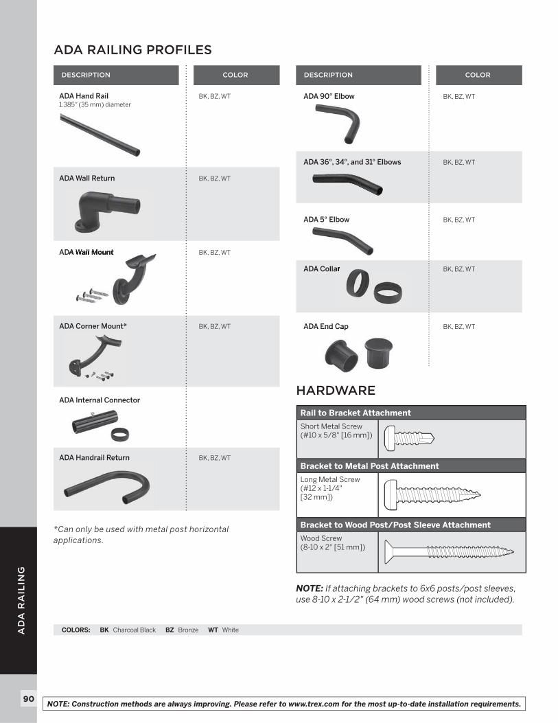
90
AD
A R
AIL
ING
90
ADA 90° Elbow BK, BZ, WT
ADA 36°, 34°, and 31° Elbows BK, BZ, WT
ADA 5° Elbow BK, BZ, WT
ADA Collar BK, BZ, WT
ADA End Cap BK, BZ, WT
ADA RAILING PROFILES
DESCRIPTION DESCRIPTION
ADA Hand Rail BK, BZ, WT1.385" (35 mm) diameter
ADA Wall Return BK, BZ, WT
ADA Wall Mount BK, BZ, WT
ADA Corner Mount* BK, BZ, WT
ADA Internal Connector
ADA Handrail Return BK, BZ, WT
COLORS: BK Charcoal Black BZ Bronze WT White
COLOR COLOR
*Can only be used with metal post horizontal applications.
NOTE: If attaching brackets to 6x6 posts/post sleeves, use 8-10 x 2-1/2" (64 mm) wood screws (not included).
HARDWARE
Rail to Bracket Attachment
Short Metal Screw(#10 x 5/8" [16 mm])
Bracket to Metal Post Attachment
Long Metal Screw(#12 x 1-1/4" [32 mm])
Bracket to Wood Post/Post Sleeve Attachment
Wood Screw(8-10 x 2" [51 mm])
NOTE: Construction methods are always improving. Please refer to www.trex.com for the most up-to-date installation requirements.
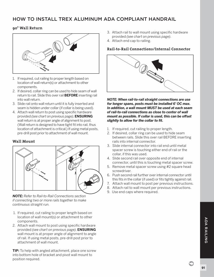
91
AD
A R
AIL
ING
91
90° Wall Return
1. If required, cut railing to proper length based on location of wall return(s) or attachment to other components.
2. If desired, collar ring can be used to hide seam of wall return to rail. Slide this over rail BEFORE inserting rail into wall return.
3. Slide rail onto wall return until it is fully inserted and seam is hidden under collar (if collar is being used).
4. Attach wall return to post using specifi c hardware provided (see chart on previous page), ENSURING wall return is at proper angle of alignment to post. (Wall return is designed to have tight fi t into rail, thus location of attachment is critical.) If using metal posts, pre-drill post prior to attachment of wall mount.
Wall Mount
NOTE: Refer to Rail-to-Rail Connections section if connecting two or more rails together to make continuous straight run.
1. If required, cut railing to proper length based on location of wall mount(s) or attachment to other components.
2. Attach wall mount to post using specifi c hardware provided (see chart on previous page), ENSURINGwall mount is at proper angle of alignment to angle of rail. If using metal posts, pre-drill post prior to attachment of wall mount.
TIP: To help with angled attachment, place one screw into bottom hole of bracket and pivot wall mount to position required.
3. Attach rail to wall mount using specifi c hardware provided (see chart on previous page).
4. Attach end cap to railing.
Rail-to-Rail Connections/Internal Connector
NOTE: When rail-to-rail straight connections are use for longer spans, posts must be installed 6' OC max. In addition, a wall mount MUST be used at each seam of rail-to-rail connections as close to center of wall mount as possible. If collar is used, this can be off set slightly to allow for the collar to fi t.
1. If required, cut railing to proper length.2. If desired, collar ring can be used to hide seam
between rails. Slide this over rail BEFORE inserting rails into internal connector.
3. Slide internal connector into rail end until metal spacer screw is touching either end of rail or the collar, if this was used.
4. Slide second rail over opposite end of internal connector, until this is touching metal spacer screw.
5. Remove metal spacer screw using #2 square head screwdriver.
6. Push second rail further over internal connector until this fi ts in the collar (if used) or fi ts tightly against rail.
7. Attach wall mount to post per previous instructions.8. Attach rail to wall mount per previous instructions.9. Use end caps where required.
HOW TO INSTALL TREX ALUMINUM ADA COMPLIANT HANDRAIL
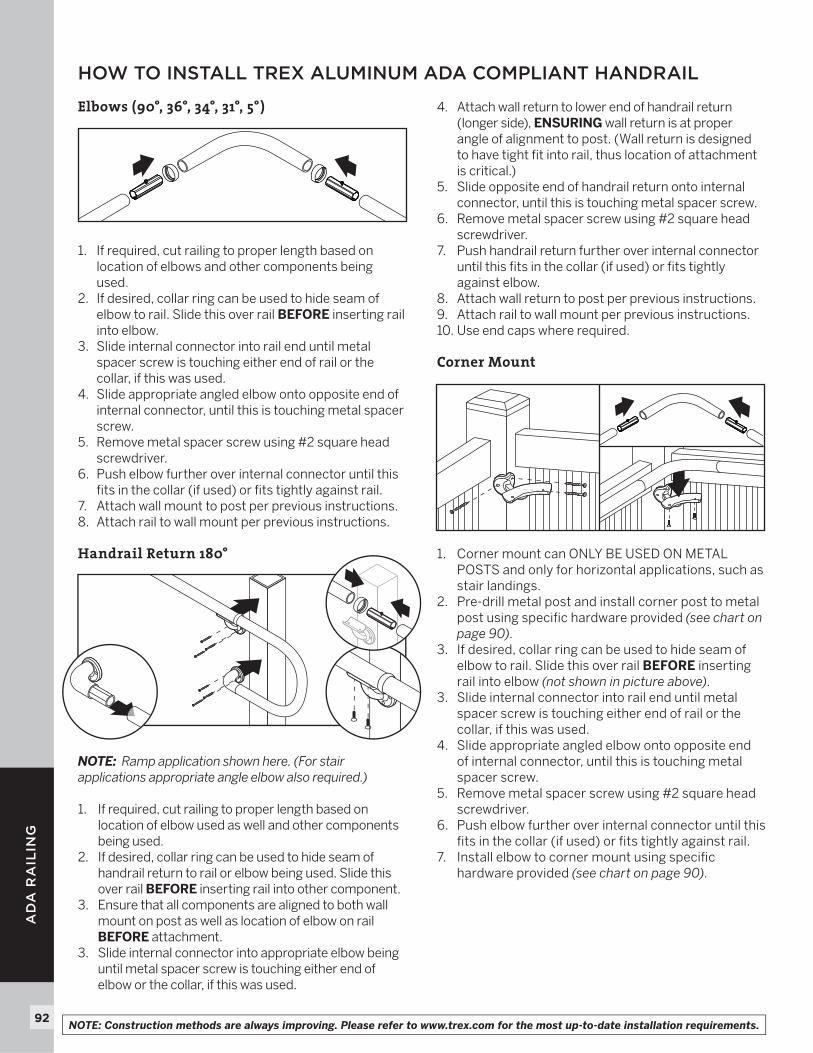
92
AD
A R
AIL
ING
Elbows (90°, 36°, 34°, 31°, 5°)
1. If required, cut railing to proper length based on location of elbows and other components being used.
2. If desired, collar ring can be used to hide seam of elbow to rail. Slide this over rail BEFORE inserting rail into elbow.
3. Slide internal connector into rail end until metal spacer screw is touching either end of rail or the collar, if this was used.
4. Slide appropriate angled elbow onto opposite end of internal connector, until this is touching metal spacer screw.
5. Remove metal spacer screw using #2 square head screwdriver.
6. Push elbow further over internal connector until this fi ts in the collar (if used) or fi ts tightly against rail.
7. Attach wall mount to post per previous instructions.8. Attach rail to wall mount per previous instructions.
Handrail Return 180°
NOTE: Ramp application shown here. (For stair applications appropriate angle elbow also required.)
1. If required, cut railing to proper length based on location of elbow used as well and other components being used.
2. If desired, collar ring can be used to hide seam of handrail return to rail or elbow being used. Slide this over rail BEFORE inserting rail into other component.
3. Ensure that all components are aligned to both wall mount on post as well as location of elbow on rail BEFORE attachment.
3. Slide internal connector into appropriate elbow being until metal spacer screw is touching either end of elbow or the collar, if this was used.
4. Attach wall return to lower end of handrail return (longer side), ENSURING wall return is at proper angle of alignment to post. (Wall return is designed to have tight fi t into rail, thus location of attachment is critical.)
5. Slide opposite end of handrail return onto internal connector, until this is touching metal spacer screw.
6. Remove metal spacer screw using #2 square head screwdriver.
7. Push handrail return further over internal connector until this fi ts in the collar (if used) or fi ts tightly against elbow.
8. Attach wall return to post per previous instructions.9. Attach rail to wall mount per previous instructions.10. Use end caps where required.
Corner Mount
1. Corner mount can ONLY BE USED ON METAL POSTS and only for horizontal applications, such as stair landings.
2. Pre-drill metal post and install corner post to metal post using specifi c hardware provided (see chart on page 90).
3. If desired, collar ring can be used to hide seam of elbow to rail. Slide this over rail BEFORE inserting rail into elbow (not shown in picture above).
3. Slide internal connector into rail end until metal spacer screw is touching either end of rail or the collar, if this was used.
4. Slide appropriate angled elbow onto opposite end of internal connector, until this is touching metal spacer screw.
5. Remove metal spacer screw using #2 square head screwdriver.
6. Push elbow further over internal connector until this fi ts in the collar (if used) or fi ts tightly against rail.
7. Install elbow to corner mount using specifi c hardware provided (see chart on page 90).
HOW TO INSTALL TREX ALUMINUM ADA COMPLIANT HANDRAIL
NOTE: Construction methods are always improving. Please refer to www.trex.com for the most up-to-date installation requirements.