railing systems for longitudinal timber deck bridges · railing systems for longitudinal timber...
TRANSCRIPT
Railing Systems for Longitudinal Timber Deck Bridges
Ronald K. Faller and Barry T. Rosson, Midwest Roadside Safety Facility,University of Nebraska-Lincoln
Michael A. Ritter and Paula D. Hilbrich Lee, USDA Forest Service,Forest Products Laboratory
Sheila R. Duwadi, Federal Highway Administration
AbstractBridge railing systems in the United States have his-torically been designed based on static load criteriagiven in the American Association of State Highwayand Transportation Officials (AASHTO) StandardSpecifications for Highway Bridges. In the pastdecade, full-scale vehicle crash testing has been rec-ognized as a more appropriate and reliable method ofevaluating bridge railing acceptability. In 1989,AASHTO published the Guide Specifications forBridge Railings which gives recommendations andprocedures to evaluate railings by full-scale vehiclecrash testing. In 1993, the National Cooperative High-way Research Program (NCHRP) published Report350, Recommended Procedures for the Safety Perfor-mance Evaluation of Highway Features, which pro-vides criteria for evaluating longitudinal barriers.Based on these specifications, a cooperative researchprogram was initiated between the University ofNebraska-Lincoln and the Forest Products Laboratory,and later the Federal Highway Administration, to de-velop and crash test several bridge railings for longitu-dinal wood decks. This paper describes the successfuldevelopment and testing of nine resulting railing sys-tems in accordance with the AASHTO PerformanceLevel 1 and 2 (PL-1 and PL-2) requirements, and theTest Level 1 and 4 (TL-1 and TL-4) requirements ofNCHRP Report 350.
Keywords: Timber Bridges, Bridge Rail, Crash Test-ing, Roadside Safety, and Longitudinal Barrier.
IntroductionThe primary purpose of a bridge railing is to safelycontain errant vehicles crossing a bridge. To meet thisobjective, railings must be designed to withstand theforce of an impacting vehicle. In designing railing sys-tems for highway bridges, engineers have traditionallyassumed that vehicle impact forces can be approxi-mated by equivalent static loads that are applied torailing elements. Although rail loads are actually dy-namic, the equivalent static load method has beenused for many years as a simplified approach to stan-dardized railing design. Until recently, the AmericanAssociation of State Highway and Transportation Of-ficials (AASHTO) Standard Specifications for High-way Bridges (1) required that rail posts be designed toresist an outward transverse static load of 44.5 kN(10,000 lb). A portion of this load was also applied toposts in the inward transverse, longitudinal, and verti-cal directions and to the rail elements. These require-ments were identical for all bridges regardless ofbridge geometry or traffic conditions. Thus, a railingfor a single-lane bridge located on a low-volume roadwas required to meet the same loading requirements asa railing for a bridge located on a major highway.
145
Despite the widespread use of design requirementsbased primarily on static load criteria, the need formore appropriate full-scale vehicle crash test criteriahas long been recognized. The frost U.S. guidelines forfull-scale vehicle crash testing were published in 1962(2). This initial l-page document provided basicguidelines for the test vehicle mass, approach speed,and impact angle and served to provide a degree ofuniformity to the traffic barrier research in progress atthe time. Through subsequent use of this document,the need for more comprehensive guidelines becameapparent, and several reports were published duringthe 1970s through the National Cooperative HighwayResearch Program (NCHRP). In 1981, NCHRP pub-lished Report 230, Recommended Procedures for theSafety Performance Evaluation of Highway Appurte-nances (3). This comprehensive report provided rec-ommendations relative to crash testing and evaluationof longitudinal barriers and served as the basis for fu-ture bridge rail crash testing requirements.
Although crash test criteria have been available formany years, the requirement to implement crash test-ing as a means of evaluating bridge railings in theUnited States has been jurisdiction dependent. Somestates implemented extensive bridge rail crash testingprograms, while others continued to exclusively usestatic load design. The first recognition of full-scalecrash testing in a national bridge specification came in1989 when AASHTO published Guide Specifications
for Bridge Railings (4). This specification presentsrecommendations for the development, testing, anduse of crash-tested bridge railings and refers exten-sively to NCHRP 230 for crash testing procedures andrequirements.
A primary concept of the AASHTO Guide Specifica-tions is that bridge railing performance needs differgreatly from site to site, and railing designs and costsshould match site needs. Thus, recommended require-ments for rail testing are based on three performancelevels: Performance Level 1 (PL-1), PerformanceLevel 2 (PL-2), and Performance Level 3 (PL-3). ThePL-1 requirements represent the “weakest” sys-tem, and the PL-3 the “strongest” system. The relation-ship between the railing performance level and re-quirements for a specific bridge depend on a numberof factors, such as the type of roadway, design speed,average daily traffic, and percentage of trucks in thetraffic mix.
The recently published NCHRP Report 350, Recom-mended Procedure for the Safety Performance Evalu-ation of Highway Features (5), provides for six test
levels for evaluating longitudinal barriers; Test Level1 (TL-1) through Test Level 6 (TL-6). Although thisdocument does not include objective criteria for relat-ing a Test Level to a specific roadway type, the lowertest levels are generally intended for use on lower ser-vice level roadways and certain types of work zoneswhile the higher test levels are intended for use onhigher service level roadways.
In 1994, AASHTO published the LRFD Bridge De-sign Specifications (6) as an update to the StandardSpecifications for Highway Bridges (1) and the GuideSpecifications for Bridge Railings (4). For crash test-ing bridge railings, three performance levels were pro-vided similar to those provided in the Guide Specifica-tions for Bridge Railings (4). Guidelines for crash test-ing bridge railings followed procedures provided inboth the AASHTO Guide Specifications and NCHRPReport 350. Yield line and inelastic analysis and de-sign procedures, as originally developed by Hirsch(7), were also provided for bridge railings as a re-placement to the 44.5 kN (10,000 lb) equivalent staticload design procedures.
Emphasis on the use of crash-tested rails for new Fed-erally funded projects has significantly increased therole of fill-scale crash testing as a means of evaluatingrailing performance. Recently, the Federal HighwayAdministration (FHWA) officially adopted NCHRP350 as a replacement for NCHRP 230 and has stronglysuggested that AASHTO also adopt the test level defi-nitions contained in NCHRP 350, thus making crash-tested railings mandatory for most bridges. Most high-ways on which wood bridges are installed will requirerailings that meet either the AASHTO PL-1 or PL-2requirements, or the NCHRP 350 TL-1 through TL-4requirements. A railing that meets either PL-3, TL-5,or TL-6 requirements currently has a verylimited application for wood bridges because of thehigh traffic volumes and speeds associated with theselevels.
As of August 1990, 25 bridge rails had been success-fully crash tested in accordance with the requirementsof the AASHTO Guide Specifications and approvedfor use on Federal-aid projects by the FHWA (8). Ofthese crash-tested railings, 24 are for concrete bridgedecks and one is for a wood deck. For wood bridges tobe viable and competitive with other bridges in the fu-ture, a range of crash-tested bridge railings for differ-ent wood bridge types was required. Based on thisneed, National emphasis was placed on developing alimited number of crash-tested railings for woodbridges.
146
B a c k g r o u n d To meet the need for crashworthy railings for woodbridges, the USDA Forest Service, Forest ProductsLaboratory (FPL), in cooperation with the MidwestRoadside Safety Facility (MwRSF) of the Universityof Nebraska-Lincoln, the FHWA, and the wood prod-ucts industry initiated a program to develop crash-tested bridge rails for longitudinal wood decks. Theprogram objectives were to develop a total of ninecrashworthy rails: three to meet AASHTO PL-1, oneto meet AASHTO PL-2, three to meet NCHRP 350TL-1, one to meet NCHRP 350 TL-4, and one in-tended for very low performance conditions. Thescope of the project was limited to railings for longitu-dinal wood decks, 252 mm (10 in.) or greater in thick-ness, and constructed of glued-laminated (glulam)timber, spike-laminated lumber, or stress-laminatedlumber. In each system, the lumber laminations areplaced edgewise and oriented with the lumber lengthparallel to the direction of traffic. A brief descriptionof each longitudinal deck bridge type is provided inTimber Bridges: Design, Construction, Inspection,and Maintenance (9).
Longitudinal glulam timber decks are constructed ofpanels that consist of individual lumber laminationsglued together with waterproof structural adhesives.The panels are 1.07 to 1.38 m (3.5 to 4.5 ft) wide andeffectively function as a large, solid block of wood.To form the bridge deck, panels are placed side byside and are interconnected by transverse distributorbeams bolted to the deck underside at intervals of 2.4m (8 ft) or less. These distributor beams are designedto transfer vertical loads between adjacent panels.They are not designed to resist lateral loads.
Spike-laminated decks are constructed of sawn lum-ber laminations 102 mm (4 in.) in nominal thickness.The individual laminations are interconnected withspikes that are typically 8 or 9.5 mm (0.3125 or 0.375in.) in diameter and 356 to 406 mm (14 to 16 in.) long.The decks are commonly manufactured in panels thatare 1.5 to 2.1 m (5 to 7 ft) wide and interconnectedwith transverse distributor beams in a manner similarto longitudinal glulam timber decks.
Stress-laminated decks are constructed of sawn lum-ber laminations that are typically 51 to 102 mm (2 to4 in.) in nominal thickness. The laminations arestressed together with high strength steel bars that areplaced through holes drilled through the center of thewide faces of the laminations. When tensioned, thebars create compression between the laminations, andthe entire deck effectively acts as a solid, orthotropicwood plate.
Test Requirementsand Evaluation CriteriaThe test requirements and evaluation criteria for thisproject followed procedures defined in the AASHTOGuide Specifications (including applicable referencesto NCHRP 230) and the NCHRP 350 criteria. Theseprocedures establish a uniform methodology for test-ing and evaluating railings so that the safety perfor-mance of different railing designs, tested and evalu-ated by different agencies, can be compared. It is im-practical and impossible to test all railings for all pos-sible vehicle and impact conditions. Therefore, theprocedures specify a limited number of tests using se-vere vehicle impact conditions and a set of evaluationcriteria against which test results may be evaluated.
Test RequirementsVehicle impact requirements for rail crash testing de-pend on the railing performance level/test level andare specified as requirements for vehicle type andweight, impact speed, and impact angle relative to thelongitudinal rail axis. Testing for PL-1 and TL-1 re-quires two vehicle impact tests while testing for PL-2and TL-4 requires three vehicle impact tests. A sum-mary of the requirements for PL-1, PL-2, TL-1, andTL-4 are shown in Table 1. In some cases, all tests fora given level may not be required if a railing with sim-ilar geometry and strength was previously tested andfound to be satisfactory.
In addition to vehicle impact requirements, theAASHTO Guide Specifications and the NCHRP 350criteria also specify requirements for data acquisitionand construction of the bridge railing. Requirementsfor data acquisition are referenced to NCHRP 230 andNCHRP 350 and include specific data collection pa-rameters and techniques that must be completed be-fore, during, and after the crash test. Construction re-quirements specify that the bridge rail be designed,constructed, erected, and tested in a manner represen-tative of actual installations. To properly assess theperformance of most bridge rails, they must also beevaluated as a system in combination with the bridgesuperstructure for which it is intended. This is veryimportant when considering rails for wood bridges be-cause the attachment of the rail to the bridge deck andthe ability of the wood superstructure to resist appliedloads may often be the controlling parameters.
Evaluation CriteriaEvaluation criteria for full-scale crash testing is basedon three appraisal areas: structural adequacy, occupantrisk, and vehicle trajectory after the collision. Criteriafor structural adequacy are intended to evaluate theability of the railing to contain, redirect, or permit
147
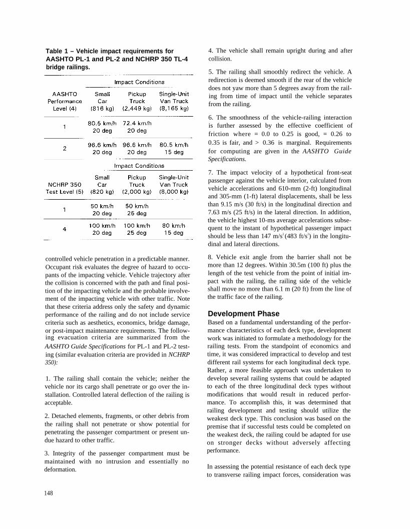
Table 1 – Vehicle impact requirements forAASHTO PL-1 and PL-2 and NCHRP 350 TL-4bridge railings.
controlled vehicle penetration in a predictable manner.Occupant risk evaluates the degree of hazard to occu-pants of the impacting vehicle. Vehicle trajectory afterthe collision is concerned with the path and final posi-tion of the impacting vehicle and the probable involve-ment of the impacting vehicle with other traffic. Notethat these criteria address only the safety and dynamicperformance of the railing and do not include servicecriteria such as aesthetics, economics, bridge damage,or post-impact maintenance requirements. The follow-ing evacuation criteria are summarized from theAASHTO Guide Specifications for PL-1 and PL-2 test-ing (similar evaluation criteria are provided in NCHRP350):
1. The railing shall contain the vehicle; neither thevehicle nor its cargo shall penetrate or go over the in-stallation. Controlled lateral deflection of the railing isacceptable.
2. Detached elements, fragments, or other debris fromthe railing shall not penetrate or show potential forpenetrating the passenger compartment or present un-due hazard to other traffic.
3. Integrity of the passenger compartment must bemaintained with no intrusion and essentially nodeformation.
4. The vehicle shall remain upright during and aftercollision.
5. The railing shall smoothly redirect the vehicle. Aredirection is deemed smooth if the rear of the vehicledoes not yaw more than 5 degrees away from the rail-ing from time of impact until the vehicle separatesfrom the railing.
6. The smoothness of the vehicle-railing interactionis further assessed by the effective coefficient offriction where = 0.0 to 0.25 is good, = 0.26 to0.35 is fair, and > 0.36 is marginal. Requirementsfor computing are given in the AASHTO GuideSpecifications.
7. The impact velocity of a hypothetical front-seatpassenger against the vehicle interior, calculated fromvehicle accelerations and 610-mm (2-ft) longitudinaland 305-mm (1-ft) lateral displacements, shall be lessthan 9.15 m/s (30 ft/s) in the longitudinal direction and7.63 m/s (25 ft/s) in the lateral direction. In addition,the vehicle highest 10-ms average accelerations subse-quent to the instant of hypothetical passenger impactshould be less than 147 m/s2 (483 ft/s2) in the longitu-dinal and lateral directions.
8. Vehicle exit angle from the barrier shall not bemore than 12 degrees. Within 30.5m (100 ft) plus thelength of the test vehicle from the point of initial im-pact with the railing, the railing side of the vehicleshall move no more than 6.1 m (20 ft) from the line ofthe traffic face of the railing.
Development PhaseBased on a fundamental understanding of the perfor-mance characteristics of each deck type, developmentwork was initiated to formulate a methodology for therailing tests. From the standpoint of economics andtime, it was considered impractical to develop and testdifferent rail systems for each longitudinal deck type.Rather, a more feasible approach was undertaken todevelop several railing systems that could be adaptedto each of the three longitudinal deck types withoutmodifications that would result in reduced perfor-mance. To accomplish this, it was determined thatrailing development and testing should utilize theweakest deck type. This conclusion was based on thepremise that if successful tests could be completed onthe weakest deck, the railing could be adapted for useon stronger decks without adversely affectingperformance.
In assessing the potential resistance of each deck typeto transverse railing impact forces, consideration was
148
given to the strength of the wood and mechanical rein-forcement. Of primary concern was loading that couldintroduce tension perpendicular to grain stress in thewood deck.
Of the three deck types, the stress-laminated deck wasconsidered the strongest for transverse railing loads,because the high strength steel bars are continuousacross the deck width. Loads developed at vehicle im-pact can be effectively distributed across the deck bythe bars, making the entire deck width effective in re-sisting the applied loads.
The spike-laminated deck was considered to be of in-termediate strength. If rail loads are applied transverseto the panel length, the loads are resisted by the spikesin withdrawal. Because of this, tension perpendicularto grain in the lumber laminations is not a concern;however, the spikes could be pulled from the deck re-sulting in longitudinal separations between the lami-nations, and additional reinforcement could berequired.
The glulam timber deck was considered to be theweakest in resisting railing loads, because the glulamtimber panels act as solid pieces of wood, and loadsapplied transverse to the panel length are most likelyto introduce tension perpendicular to grain and failurein the upper panel section. Mechanical reinforcementwas considered necessary for longitudinal glulam tim-ber decks to resist railing loads without damage. Thus,the glulam timber deck was considered the weakestdeck for transverse railing loads and was selected forfull-scale crash testing. If bridge railings performedacceptably on the glulam timber system, it was ratio-nalized that the railings could be adapted to other lon-gitudinal wood bridge decks with no reduction in rail-ing performance.
The primary emphasis of the railing design processwas to develop rails that would meet the requirementsof the AASHTO Guide Specifications and NCHRP350. Additionally, it was determined that considera-tion should be given to (1) extent of probable damageto the structure after vehicle impact and the difficultyand cost of required repairs; (2) adaptability of therailing to different wood deck types; (3) rail systemcost to the user, including material, fabrication, andconstruction; (4) ease of railing construction andmaintenance; and (5) aesthetics.
The conclusion of the development phase involved thedesign of several railing systems and preparation ofplans and specifications for testing. The selection and
design of these final systems were based on a reviewof other railings that had been successfully crashtested, as well as those that are currently used on woodbridges but had not been crash tested. To the extentpossible, feasible designs were evaluated using com-puter simulation models. Although several provencomputer models were used, it was difficult to adaptthe programs for wood components because the be-havior and properties of the wood systems at ultimateloading were unknown. Data collected during thecrash testing were used to refine input parameters andto more accurately predict railing performance insubsequent tests.
Test MethodologyTesting of all bridge rails was conducted at the Mid-west Roadside Safety Facility in Lincoln, Nebraska.The site is located at an airport and was formerly ataxiway and parking area for military aircraft. It in-cludes approximately 11 ha (27 acres) of concretepavement and 1.6 ha (4 acres) of soil surface. To per-form the rail testing, a test bridge was constructed thatmeasured approximately 2.4 m (8 ft) wide and 28.6 m(93.75 ft) long, in five simply-supported spans mea-suring 5.72 m (18.75 ft) each. The deck was con-structed of 273-mm (10.75 -in.) thick glulam timberpanels, 1.2 m (4 ft) wide. The glulam timber for thedeck was Combination No. 2 Douglas Fir given in theAASHTO Standard Specifications for HighwayBridges (1) and was treated with pentachlorophenol inheavy oil in accordance with American Wood Pre-servers’ Association (AWPA) Standard C14 (10). Twoglulam timber panels were placed side by side toachieve the 2.4-m (8-ft) width, and transverse distrib-utor beams were attached to the deck underside perAASHTO requirements (l). The test bridge was sup-ported by concrete footings that were placed in exca-vations so that the top of the test bridge was level withthe concrete surface at the site.
Vehicle propulsion and guidance were provided bysteel cable configurations. For propulsion, a reversecable tow with a 1:2 mechanical advantage was used.A cable was attached to the front of the vehicle, routedthrough a series of pulleys, and was connected to atow vehicle that traveled in a direction opposite to thetest vehicle. The unoccupied test vehicle was thenpulled by the tow vehicle and released from the towcable approximately 9.2 m (30 ft) prior to impact. Avehicle guidance system developed by Hinch wasused to steer the test vehicle (11). Using this system,the the left front wheel hub is attached to a tensionedsteel cable that maintains the vehicle’s direction alonga designated straight path. Approximately 9.2 m (30
149
ft) from impact, the guidance connection is shearedoff and the vehicle separates from the guidance cable.
Data acquisition parameters and techniques for thecrash testing program were based on requirements ofthe AASHTO Guide Specifications and NCHRP 350and followed three testing phases: pretest, test, andpost-test. In the pretest phase, the as-built bridge railand vehicle were documented using photography anddrawings that indicated the applicable configuration,dimensions, and vehicle weight. During the test phase,data regarding the vehicle impact speed, impact angle,trajectory, and accelerations were collected primarilythrough the use of high-speed motion picture photog-raphy and accelerometers mounted on the vehicle. Inthe post-test phase, the condition of both the railing,bridge superstructure, and vehicle were documentedusing photography and standardized damage assess-ment methods, including the Traffic Accident DataScale (12) and Vehicle Damage Index (13). Addi-tional instrumentation was placed on some railings toassess vehicle impact forces transmitted to the bridgerail and superstructure (14).
Successfully Tested RailingsAs a result of the development and testing program,nine bridge railings were successfully developed andtested for longitudinal wood decks. Three of the rail-ings were tested at PL-1, one was tested at PL-2, threewere tested to TL-1, one was tested at TL-4, and onewas tested primarily for low-volume forest road appli-cations at impact conditions less than TL-1. Each rail-ing was tested on the glulam timber deck and is adapt-able to the spike-laminated and stress-laminateddecks. All the PL-1, PL-2, and TL-4 designs em-ployed posts spaced 1.9 m (6.25 ft) on-center and uti-lized high strength steel bars through a portion of thebridge deck to act as reinforcement in distributing rail-ing loads without damage to the bridge. Two of thethree TL-1 designs employed posts spaced 1.9 m (6.25ft) on-center, while the third TL-1 design was a curbrailing configured with scuppers spaced 3.0 m (10 ft)on-center. The railing design for conditions less thanTL-1 consisted of a curb railing with scuppers spaced2.9 m (9.5 ft) on-center. Glulam timber for the railmembers was Combination No. 2 Douglas Fir asgiven in the AASHTO Standard Specifications forHighway Bridges (1), treated with pentachlorophenolin heavy oil to AWPA Standard C14 requirements(10). Sawn lumber for posts, curbs, scuppers, andspacer blocks was No. 1 Douglas Fir (1), treated withcreosote to AWPA Standard C14 requirements (10).
A detailed discussion of the testing and results foreach railing system is beyond the scope of this paperand, for most of the railing systems, is presented indetail in previous publications (14-18). Overall, nosignificant damage to the test bridge was evident fromany of the vehicle impact tests. For the railing systemswith glulam timber rails, damage to the railing wasprimarily gouging and scraping resulting from the ve-hicle impact. All glulam timber railing remained intactand serviceable after the tests and replacement of therailing was not considered necessary. For the steelthrie beam railings, there was permanent deformationin the rail and post in the vicinity of the impact loca-tion. This would necessitate replacement of specificrailing and post members, but damage was relativelyminor considering the severity of the impact. A briefdescription of each railing that met all test criteria fol-lows.
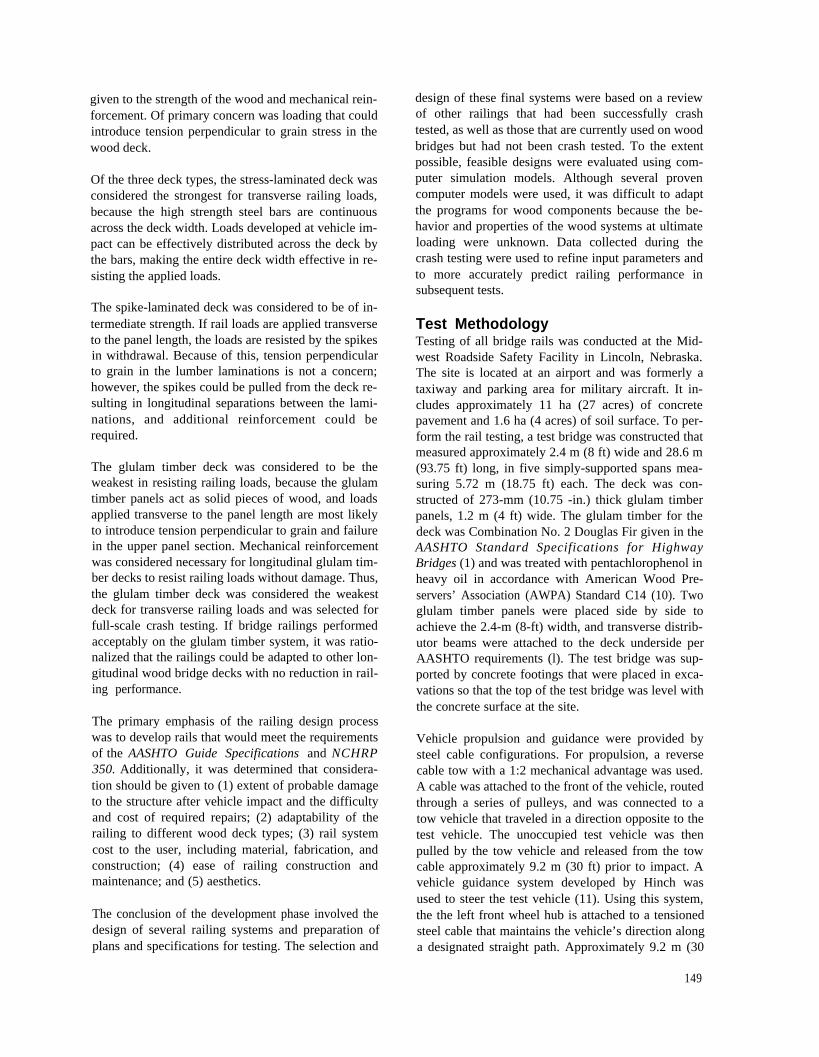
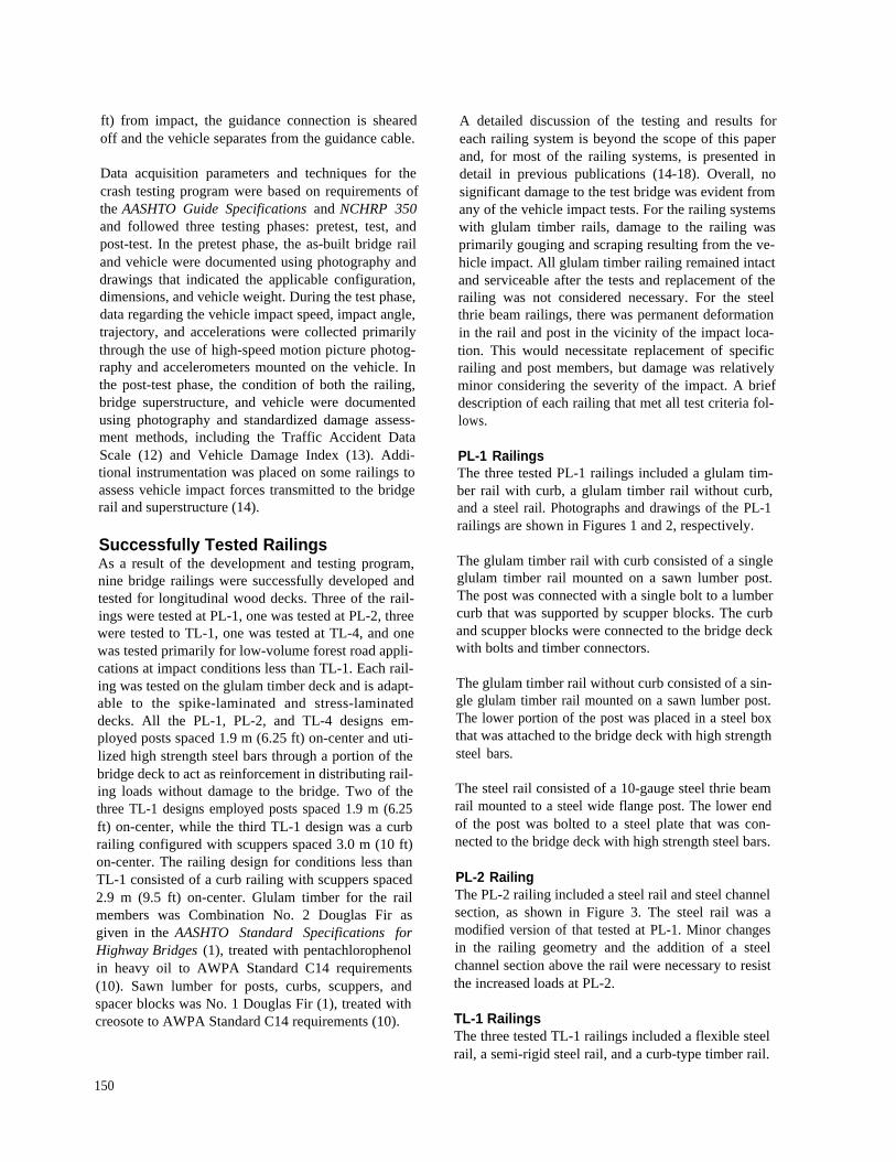
PL-1 RailingsThe three tested PL-1 railings included a glulam tim-ber rail with curb, a glulam timber rail without curb,and a steel rail. Photographs and drawings of the PL-1railings are shown in Figures 1 and 2, respectively.
The glulam timber rail with curb consisted of a singleglulam timber rail mounted on a sawn lumber post.The post was connected with a single bolt to a lumbercurb that was supported by scupper blocks. The curband scupper blocks were connected to the bridge deckwith bolts and timber connectors.
The glulam timber rail without curb consisted of a sin-gle glulam timber rail mounted on a sawn lumber post.The lower portion of the post was placed in a steel boxthat was attached to the bridge deck with high strengthsteel bars.
The steel rail consisted of a 10-gauge steel thrie beamrail mounted to a steel wide flange post. The lower endof the post was bolted to a steel plate that was con-nected to the bridge deck with high strength steel bars.
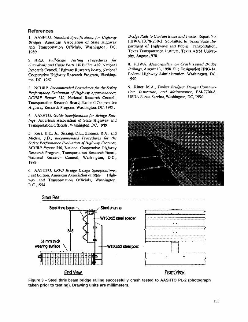
PL-2 RailingThe PL-2 railing included a steel rail and steel channelsection, as shown in Figure 3. The steel rail was amodified version of that tested at PL-1. Minor changesin the railing geometry and the addition of a steelchannel section above the rail were necessary to resistthe increased loads at PL-2.
TL-1 RailingsThe three tested TL-1 railings included a flexible steelrail, a semi-rigid steel rail, and a curb-type timber rail.
150
Photographs and drawings of the TL-1 railings areshown in Figures 4 and 5, respectively.
The flexible steel rail consisted of a 12-gauge W-beamrail mounted to a breakaway sawn lumber post. Thelower end of the post was placed between two steelangles that were connected to the vertical edge of thebridge deck with lag screws.
The semi-rigid steel rail consisted of a 12-gauge W-beam rail mounted to a steel wide flange post. Thepost was bolted to a steel plate which was bolted to thebridge deck surface.
The low-height, curb-type timber rail was constructedwith a glulam timber rail and supported with scupperblocks. The curb and scupper blocks were connectedto the bridge deck with bolts and timber connectors.
TL-4 RailingThe TL-4 railing included a glulam timber rail withcurb, as shown in Figure 6. The glulam timber raiIwith curb consisted of a single glulam timber railmounted on a sawn lumber post and was a modifica-tion of the curb system tested at PL-1. Because of thegreater loads at TL-4, rail and post sizes were in-creased and bolts and timber connectors attaching thecurb and scupper to the bridge deck were increased.
Low Performance RailingThe low performance railing developed for impactconditions less than TL-1 included a low-height tim-ber curb rail, as shown in Figure 7. Three geometrieswere considered for the curb rail — a square shape, arectangular shape, and a trapezoidal shape. The curbrail was constructed with sawn lumber and supportedwith scupper blocks. The curb and scupper blockswere connected to the bridge deck with bolts.
Concluding RemarksThis program clearly demonstrates that crashworthyrailing systems are feasible for longitudinal wooddecks. Even at high-impact conditions required byAASHTO PL-2 and NCHRP 350 TL-4, the railingsystems performed well with no significant damage tothe bridge superstructure. With the development ofcrashworthy railing systems, a significant barrier tothe use of longitudinal deck wood bridges has beenovercome.
Figure 1 — Photographs of bridge railings suc-cessfully crash tested to AASHTO PL-1(photographs taken prior to testing).
151
Figure 2 – Drawings of bridge railings successfully crashare millimeters
tested to AASHTO PL-1. Drawing units
152
References
Figure 3 – Steel thrie beam bridge railing successfully crash tested to AASHTO PL-2 (photographtaken prior to testing). Drawing units are millimeters.
153
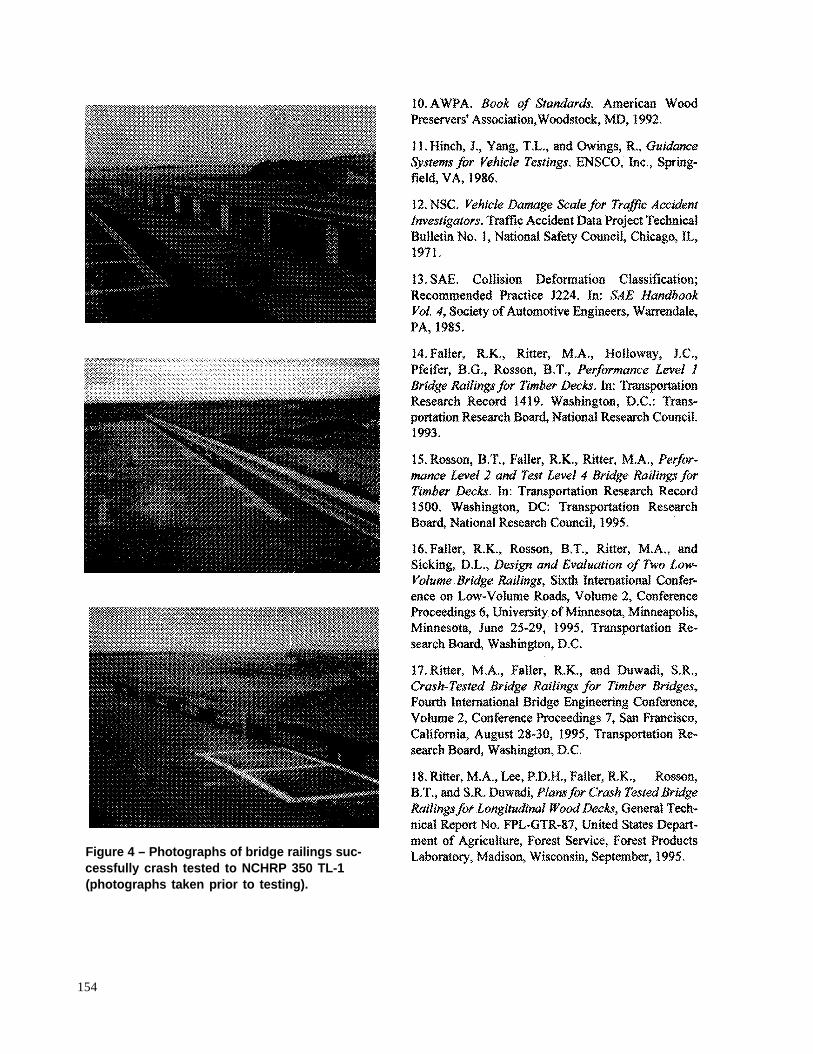
Figure 4 – Photographs of bridge railings suc-cessfully crash tested to NCHRP 350 TL-1(photographs taken prior to testing).
154
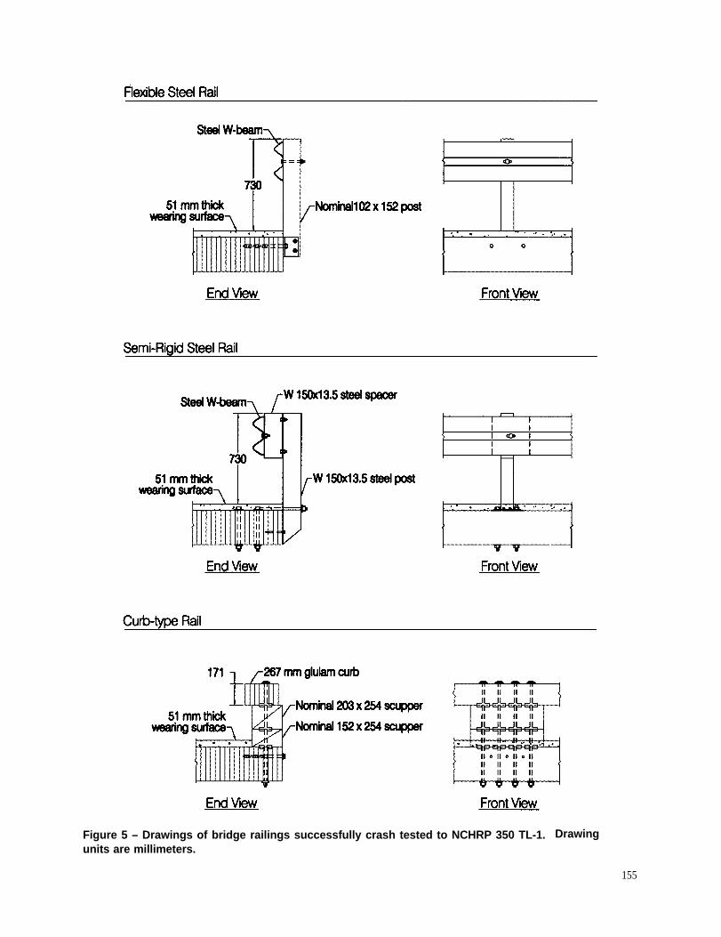
Figure 5 – Drawings of bridge railings successfully crash tested to NCHRP 350 TL-1.units are millimeters.
Drawing
155
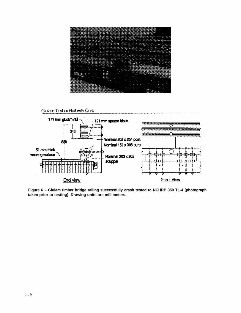
Figure 6 – Glulam timber bridge railing successfully crash tested to NCHRP 350 TL-4 (photographtaken prior to testing). Drawing units are millimeters.
1 5 6
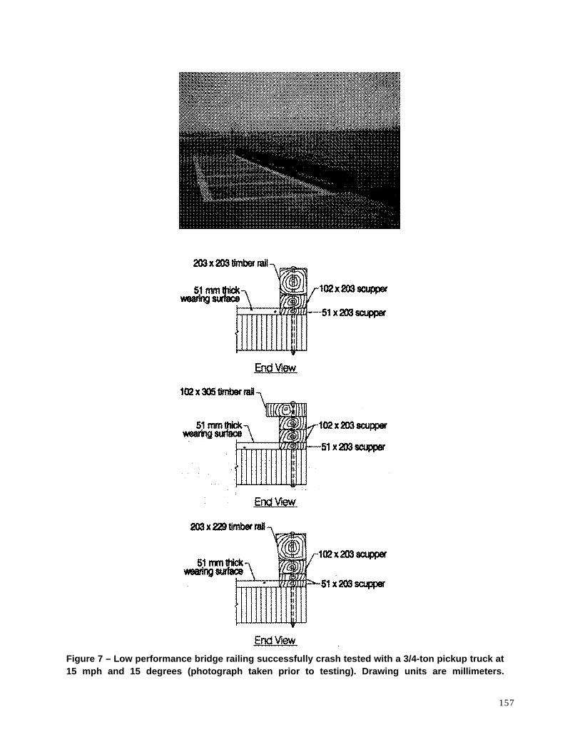
Figure 7 – Low performance bridge railing successfully crash tested with a 3/4-ton pickup truck at15 mph and 15 degrees (photograph taken prior to testing). Drawing units are millimeters.
157

In: Ritter, M.A.; Duwadi, S.R.; Lee, P.D.H., ed(s). Nationalconference on wood transportation structures; 1996 October23-25; Madison, WI. Gen. Tech. Rep. FPL- GTR-94.Madison, WI: U.S. Department of Agriculture, Forest Service,Forest Products Laboratory.