rainplus - syphonics.com.au
TRANSCRIPT

RAINPLUS
Siphonic rainwater drainage system

2
Valsir headquarters and production plant - Vestone (Italy)

3
RAINPLUS
MADE IN ITALY
Watch the Rainplus videovalsir.it/u/rainplus
MADE IN ITALY
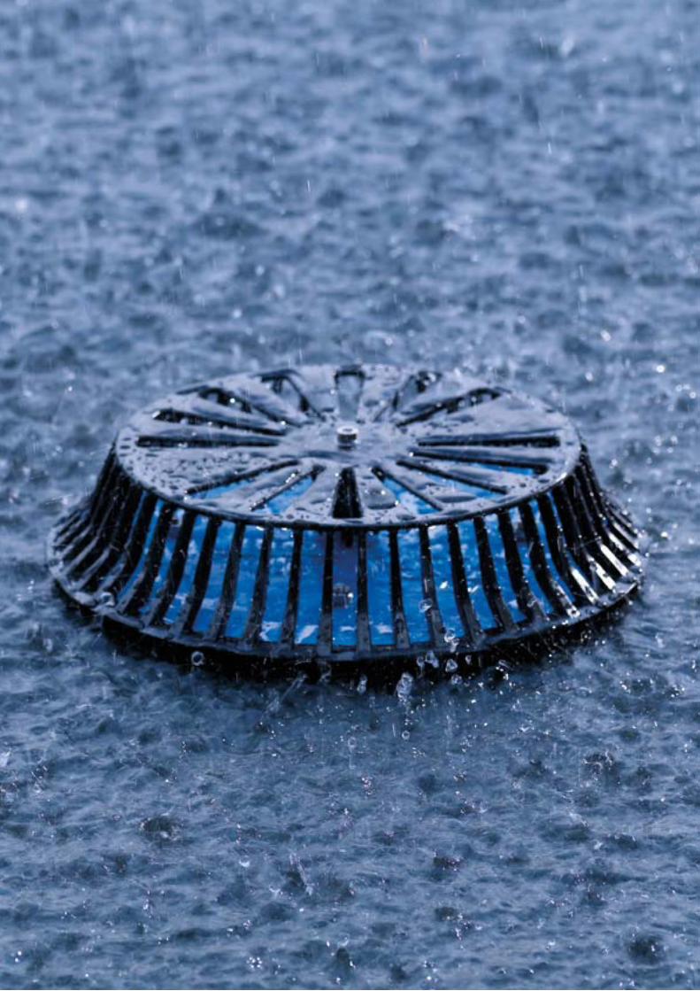
Rainplus®, the ultimate solution in case of rain
Rainplus® is a siphonic rainwater drainage system designed to reach maximum drainage performance with the lowest levels of water accumulation on the roof.Valsir Rainplus® fully meets the demands of increasing rainfall levels rainwater drainage from medium to large size buildings in total safety.
The system uses the building height as the driving force to generate high speed flow rates thus maximizing drainage efficiency.
Rainplus® allows the entire quantity rainwater to be directed to any part of the building, thus enabling the implementation of the most modern rainwater harvesting systems.The harvesting and conservation of water are essential parameters to obtain the of Green Building marks.
This technology has many advantages; such as the significant reduction in costs and installation times, as well as an increase in the performance of the entire drainage system.
The Rainplus® siphonic system is made up of special roof outlets that are designed and tested according to American Standard ASME A112.6.9 and European Standard EN 1253.
These outlets are connected to Valsir HDPE pipes and fittings, which are sized in order to work under negative pressures, at high flow rates and with a full bore. This is possible thanks to the special configuration of the Rainplus® roof outlets, which prevent air from entering the pipes when the design rainfall intensity value is reached. In this way, the “hydraulic engine” of the system is generated by the height of the roof in relation to the drainage point and not by the amount of water accumulated on the roof.
The hydraulic principles of Rainplus® are therefore different from those of conventional drainage systems thus requiring a decidedly more advanced technical preparation in design and calculation as well as in system installation, since the accurate and proper design and installation of the hydraulic circuits has a direct influence on the performance of the entire siphonic system.
4

A quality system
The Rainplus® siphonic system is made up of roof outlets, pipe clamps and other clamping accessories, Valsir HDPE pipes and fittings, a software for 3D design and extremely professional computations.Valsir HDPE pipes and fittings are manufactured according to EN 1519 and have been approved to many standards worldwide (CSTB, IIP, KIWA, SKZ, ETA, Lloyd’s Register, etc.).
The light weight and wide range of pieces available make Valsir HDPE the ideal solution for the construction of siphonic drainage circuits. Valsir HDPE also offers great installation flexibility thanks to the various jointing methods, such as butt-welding and electrofusion.
HU NL SEBE DK NOCHAT UKDE IT ROFRAU ZARU UASGPL RS
5
CHARACTERISTICS OF EXCELLENCE
The advantages of Rainplus®
•Cheap. When compared to conventional systems, Rainplus® requires a lower number of roof outlets and allows a substantial reduction in pipe diameters, in the number of fittings required and in the number of downpipes: this results in savings of up to 80% on vertical pipes and from 20% to 30% across the entire system.
•Space saving. The roof outlets are connected to single horizontal collector pipes that are fitted without fall and the downpipes are positioned anywhere along the building perimeter, thus avoiding any interference.
•High performance. When in operation drainage pipes flow at 100% over the entire system. Draining speed is therefore greater resulting in the self cleaning action of the pipework.
•Sustainability. The ease in directing pipes to storage tanks makes the collection of rainwater easier for reuse in irrigation systems, fire ponds and tanks for non-potable uses.
•Time and labour saving. Construction programmes are accelerated due to reduced installation times moreover. Less groundwork is required due to the reduced number of embedded pipes.
•Increased design flexibility. Complete control over downpipe location and absence of embedded pipes causes increased design flexibility of the siphonic system.
•The Valsir Rainplus® system and HDPE are produced with completely recyclable materials which can be recovered at the end of their useful life. The production processes employed are energy efficient and have reduced impact. Valsir has adopted the Green Building principles in terms of respect for the environment and conservation of resources, pipes and fittings are in fact certified by the prestigious Singapore Green Building.
SGBP-2015-415

Flow in a conventional outlet
In conventional roof drainage systems, the outlet does not incorporate any sort of insert or device, hence the flow entering the system is characterized by a vortex pulling air into the pipes.
6
IN COMPARISON WITH CONVENTIONAL SYSTEMS
A conventional drainage system can be designed for large surfaces but does not cut off air flow into the pipe. For this reason pipes are sized for filling ratios of 20% or 33% (depending on national or local standards and regulations) allowing considerable amounts of air into the pipes up to 80% or 67% of the pipe section.
In conventional roof drainage, outlets are simple “funnels” installed on the roof covering and connected to the downpipes which are as high as the building and water collectors, which require a gradient of at least 1%, are dimensioned for a maximum filling factor of 70%.
When water collectors are very long and it is not possible to provide the minimum slope necessary due to the limited space available, the only solution is to increase the size of the pipes with a consequent rise in installation costs.
There are two types of rainwater drainage systems: conventional systems that are incorrectly called gravity systems, and the Rainplus® siphonic system, which is also known as vacuum system or full section system.
Both use the force of gravity but in a decidedly different manner, resulting in differences in performance, design and calculation.

Flow in a Rainplus® outlet
With the Rainplus® siphonic drainage system, at design flow values, the roof outlets prevent air from entering and forming vortex, thus ensuring the system works at full capacity; in such conditions design can be based on the equations of fully developed flow rates operating at positive or negative pressures (Bernoulli’s energy conservation principle).
7
The Rainplus® siphonic drainage system is made up of special outlets incorporating an anti-vortex plate that prevents air from entering the pipes. The outlets are connected through short pipes of relatively small diameters to the horizontal water collector which is located just under the building roof.
The collector pipe, generally installed at the highest possible position, runs horizontally (no fall angle is required) until it is connected to the downpipe. The downpipe drops into the drainage line which is buried in the ground and conveys the water straight into a collection tank or into the municipal stormwater mains.
The absence of air in the system allows it to work 100% full of water, making use of the entire pipe section and vastly increasing flows, that are 10 times faster when compared to conventional drainage systems.

8
Valsir production and logistic plant - Vobarno (Italy)

Bernoulli’s principle
In fluid dynamics, Bernoulli’s principle states that for an inviscid flow, an increase in the speed of the fluid occurs simultaneously with a decrease in pressure or a decrease in the fluid potential energy. Bernoulli’s principle is named after the Dutch-Swiss mathematician Daniel Bernoulli who published his principle in his book Hydrodynamica in 1738.
9
p2
v2
h2
h1
v1
p1
12⋅ ρ ⋅ v 1
2 + ρ⋅ g ⋅ h1 + p1 =12⋅ ρ ⋅ v 2
2 + ρ⋅ g ⋅ h2 + p2 + ∆ploss
Rainplus® is defined as a siphonic rainwater drainage system because it is based on the same principle as a siphon. The siphon is in general a reversed U shaped pipe used to pour a fluid from one container to another located in a lower position.When the pipe is full, the fluid contained in the longer stretch of pipe tends to fall due to its weight causing the suction of the liquid in the shorter section, which is lighter in weight.
This process only starts when the pipe is completely full and continues until a balance between the two containers is reached: either when the two containers reach the same level or when the fluid level in the higher container goes below the pipe inlet section.
The driving force that causes this effect is a result of the difference in height of the two containers: the bigger the difference, the stronger the driving force and, as a consequence, the greater the flow speed in the pipe.
RAINPLUS®, HOW DOES IT WORK?
The performances of the Rainplus® siphonic drainage system are therefore decidedly better than those of a conventional system where the driving force is generated exclusively by the amount of water that accumulates on the roof. When the siphonic drainage system works at full capacity, the “siphon effect” is triggered resulting in a driving force that is proportionate to the height of the roof and the end of the circuit, which is typically located at ground level.
Such power generates levels of positive and negative pressures in specific points of the circuit in this way the speed and, as a consequence, the flow rates of the system (Bernoulli’s principle) are rapidly increased.

Rainplus®, integrated engineering
A high degree of understanding of the Rainplus® operating rules and system flow regime is required to design and construct correctly performing siphonic systems.Unlike conventional gravity systems, a high degree of engineering and expertise is necessary, both in the design and construction phase.
10
EN 1253 and ASME A112.6.9 technical standards are used to evaluate the performances of a siphonic system and, as they define the measurement method of the flow rates as a function of the water depth on the roof, they allow the flow regime phases to be analyzed.
FLOW STAGES

11
Q1
h1
Stage 1. With a moderate flow, of 10 or 15% of the design rainfall intensity value, the roof outlet works as in a conventional system and the flow is defined “gravity flow”, since air content in the pipes is elevated.
Q2
h2
Stage 2. When the water discharged from the roof is between 10 to 15% and 60% of the full bore flow condition, water flow is discontinuous and the system therefore fluctuates from a gravitational flow regime to a full siphonic action. At these rainfall values the water that accumulates on the roof fills the outlet, cutting off air flow into the pipe and triggering the siphonic action. The speed of water discharged therefore increases, which results in falling water levels, allowing air to be drawn into the piping network and breaking the siphon; for this reason this stage is called “plug flow”.
Q3
h3
Stage 3. When the water discharged is between 60% and 95% of the design rainfall intensity value, the pipes are completely full of water, although many air bubbles are still present. This stage is called “bubble flow” and features high flow speed generated by the siphonic effect.
Q4
h4
Stage 4. When the flow is over 95% of the design rainfall intensity value, the siphonic effect operates at full capacity reaching maximum velocity with no air entering the pipes. This stage is called “full flow” and does not produce noise or vibrations.
12

Rainplus® Overflow Kit
Local regulations or standards on the design of rainwater systems may require emergency systems (also known as overflow systems) able to drain unexpectedly intense rainfall exceeding the design rainfall level.
Valsir supplies a patented product that allows a Rainplus® siphonic outlet to be transformed into an emergency siphonic outlet by simply adding an Overflow Kit that is adjustable in height and capable of maintaining the same drainage performance.
13
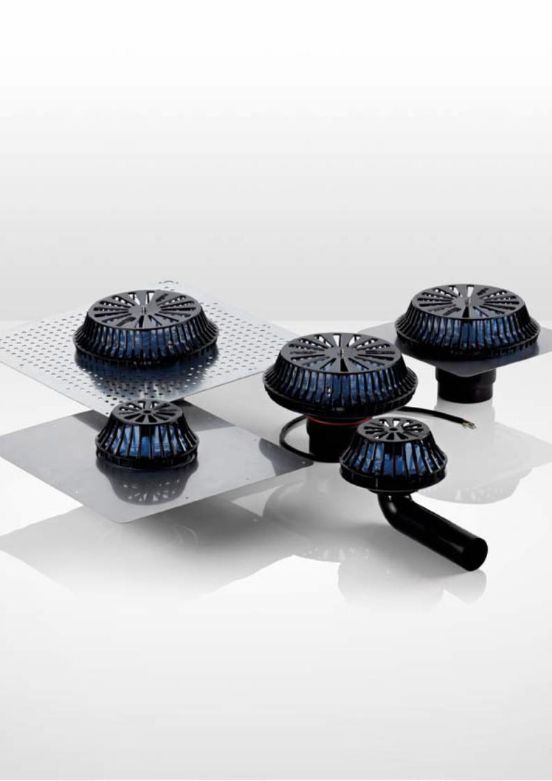
THE COMPONENTS: OUTLETS
High performances and safety
One of the key elements of the system is the Rainplus® outlet that has been designed and manufactured to meet the requirements and testing criteria set by the international standards EN 1253 and ASME A112.6.9. The main components of the Rainplus® outlets are made of stainless steel or molded aluminium alloy, protected by a special resin making them long-lasting.
These are the main features.•Wide range of drainage flows (up to 65 l/s with
Rainplus® 110 and up to 14 l/s with Rainplus® 56);•reduced roof water levels required to trigger the
siphonic action;•no swirls thanks to the special profile of the anti-
vortex disk and reduced pressure losses at the inlet;
•low noise levels and maximum operation stability;•easy installation thanks to the reduced number
of components and compact size. For example, Rainplus® 56, in the version with horizontal connection, can be installed inside the roof slab thanks to a height of just 104 mm;
•connection with the Valsir HDPE system is extremely reliable;
•suitable for installation in gutters, even of small dimensions, or on roofs covered with any type of waterproofing material.

14

15
THE COMPONENTS: BRACKETING SYSTEMS
Bracketing systems
Valsir offers a wide range of bracketing systems and accessories to install the entire drainage network. The Rainplus® bracketing system, composed of special clips as well as support rails and relative accessories, is designed to resist the forces of heat contraction and expansion in the drainage network and is available in diameter 40 mm up to diameter 315 mm.The Rainplus® system also includes clips with M10 expansion anchors, clips for M10 threaded rods for mounting on support rails, clips for 1/2” and 1” threaded rods for wall and ceiling mounting.
The bracketing system range allows:•easy pre-fabrication;•rapid and simple ceiling mounting of long
stretches of collector pipes;•mounting of the entire drainage network using a
reduced number of bracketing pieces;•alignment of clips and Valsir HDPE pipes with the
support rail;•capacity of absorbing heat expansion and
contraction of the drainage network;•installation without special tools;•the clips are anchored to the pipes and support rail
using high resistance bolts.

16

17
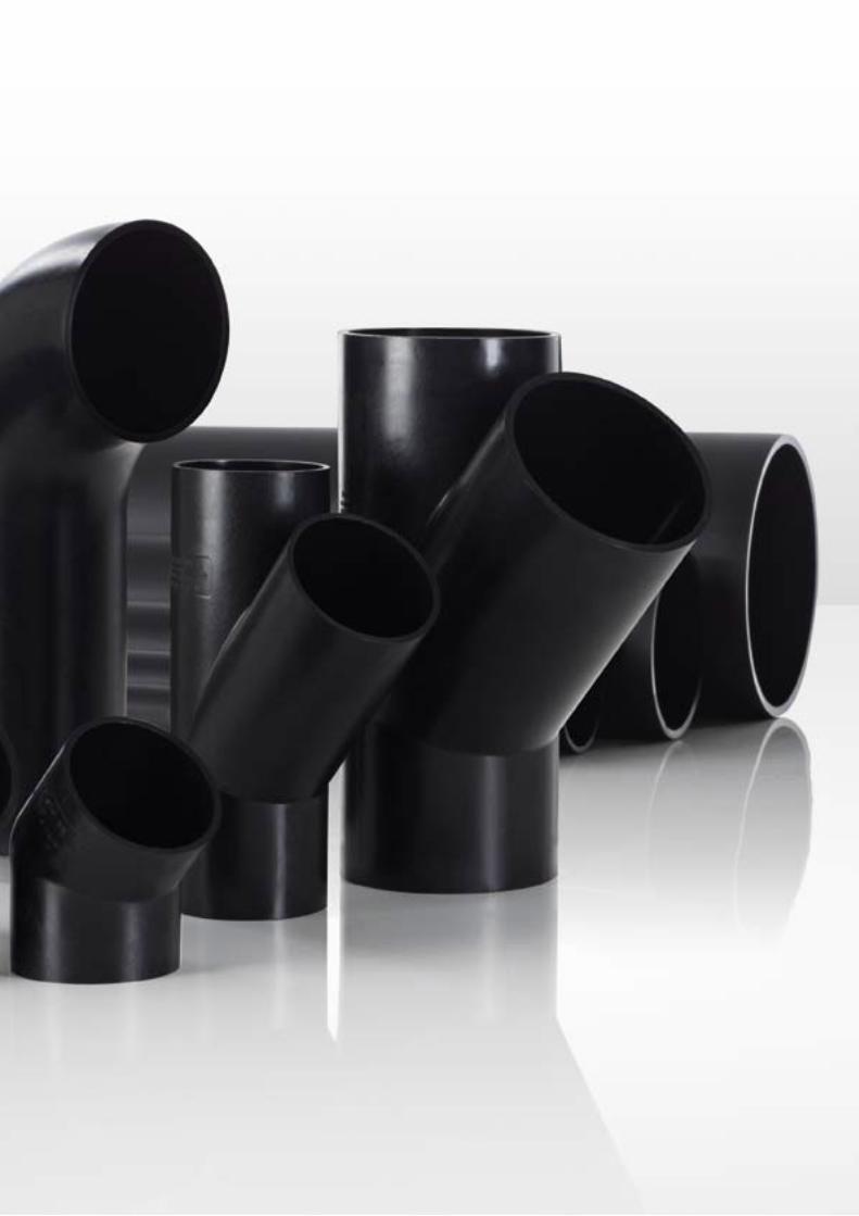
The advantages of using the Valsir HDPE system
The Valsir HDPE product line has been developed conventional and siphonic drainage systems and it is characterised by a wide range of fittings such as access pipes, elbows, reducers and reduced branches.
•Wide range of diameters from DN 32 mm to DN 315 mm, available in SDR 26 and SDR 33.
•The pipes are stabilized to reduce dimensional variations and contain carbon black for UV light resistance.
•Possibility of prefabrication to reduce assembly time on site and possibility of creating special pieces for particular applications and solutions.
•High chemical resistance to substances dissolved in civil and industrial waste waters.
•Resistance to intermittent discharges at temperatures as high as 95°C.
•High resistance to extremely rigid temperatures as low as -40°C.
•Excellent abrasion resistance and mechanical strength.
•Highly versatile and easy to install thanks to its light weight and numerous connection methods that allow wastage to be reduced to a minimum.
•Wide range of transition fittings for connection to other waste systems such as cast iron, PE, PP, PVC.
•The completely recyclable product and the production processes used are all based on the Green Building principles, respecting the environment and conserving resources.
THE COMPONENTS: PIPES AND FITTINGS
High density polyethyleneThe pipes and fittings are made of high density UV light resistant polyethylene that guarantees high mechanical resistance, excellent abrasion resistance, extremely smooth surfaces and high resistance to chemical agents.
18

19
Watch the video
EASY AND QUICK INSTALLATION
Manual butt-welding
Thanks to the extremely light weight of polyethylene, pipes and/or fittings up to a 63 mm diameter can be butt-welded using a manual process which involves the use of a heating plate only. It’s an extremely convenient jointing method on site.
Machine butt-welding
Valsir supplies butt-welding machines that weld up to 315 mm diameters. This process is extremely useful for the prefabrication of system parts that are then installed and connected on site using other jointing methods, such as welding through electrofusion sleeves.
Electrofusion couplings
By means of the electrofusion couplers that are available in 40 mm diameters to 315 mm diameters, all system parts can be prepared. Valsir supplies two types of welding machines that guarantee rapid, easy and extremely reliable welding.

20
Renault - Novo Mesto (Slovenia)

21
REFERENCES
Blue Route Mall - Capetown (South Africa)
Prima Pearl - Melbourne (Australia)
General Electric Oil & Gas - Perth (Australia)
Claudelands - Hamilton (New Zealand)
Theater Daoiz e Velarde - Madrid (Spain)
22
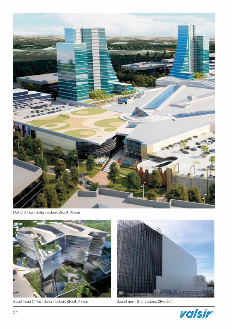
Spendrups - Grängesberg (Sweden)Sasol Head Office - Johannesburg (South Africa)
Mall of Africa - Johannesburg (South Africa)

23
Other referencesCalzedonia factory (Serbia), Bridgestone plant (India), KRKA plant (Slovenia), McDonald’s (Italy), Spar market (Slovenia), K-Mart market (Australia), Mercator market (Slovenia), Unilever logistic (Greece), Milano Orio al Serio airport (Italy), Nave de Vero shopping center (Italy), Globo Calzature factory (Italy), Radisson Hotel (South Africa), Coca Cola Amatil factory (Australia), Weleda (France), Mall of the South (South Africa), 90 Grayston (South Africa), The Villa Mall - Pretoria (South Africa), Menlyn Park Mall - Pretoria (South Africa).
BBVA - Madrid (Spain)
Standard Bank - Johannesburg (South Africa)
Pick Point Heliport - Auckland (New Zealand)
IKEA - Tempe - Sydney (Australia)
Valeo - Skawina (Poland)
TWP Melrose Arch - Johannesburg (South Africa)
Adria - Novo Mesto (Slovenia)

24

25
TECHNICAL SUPPORTAND ASSISTANCE
Valsir provides complete support both during the designing phase and on site, thanks to a first class technical office made up of a team of highly experienced engineers, capable of dealing with the most complex system requirements.
Valsir also boasts an important training centre called Valsir Academy catering for clients, distributors, plumbers and planners. Two highly equipped halls are available where theoretical and practical courses are organized on the use and design of water supply systems using the Silvestro software, a program that was developed specifically within Valsir.

26
THE RAINPLUS®
SOFTWARE
Siphonic drainage systems are designed with the use of the advanced Rainplus® software that is capable of calculating and sizing in compliance with technical Standards VDI 3806 and BS 8490. This software has many strong points:•import of 2D or 3D drawings of the building;•circuit observation point variation with three-
dimensional rotation;•numerous drawing commands including automatic
generation of inlet branches and 45° double elbows;
•calculation and verification of dimensional limits imposed by technical standards with diagnostics window;
•automatic flow optimization for system balancing;•complete calculation of the material list and the
necessary welding operations;•export of results and drawings.

27
QUALITY AND SUSTAINABILITY
Efficient processes and reliable products are not the only parameters used to evaluate a company conduct: today, in fact, the capacity of the company and its management team to design and implement production processes that are sustainable from an environmental point of view are of equal importance.
Valsir has always been committed to the manufacture of recyclable products and the implementation of sustainable processes, in line with the most advanced Green Building principles (green building and environmentally friendly project design), and today boasts highly sustainable production plants which, thanks to the use of renewable energy and planning that aim at the conservation of resources, have obtained a Class A energy certificate.
The consistency of Valsir commitment is demonstrated by its product approvals which amount to 170 in total, obtained around the world from the most severe certification bodies (figure updated on 01/06/2015), and by the certified quality system in compliance with the European Standard UNI EN ISO 9001:2008.
Production processes and management systems that are verified, monitored and certified.
Sustainable production plants and processes, use of renewable energies, sustainability of resources.
Products that are verified, monitored and certified by recognized certification bodies.
Recyclable products and low impact production processes in line with the Green Building principles.

L02-401/5 – Giugno 2015
THE VALSIR RANGE
WASTE SYSTEMS SUPPLY SYSTEMS GAS SYSTEMS
FLUSH SYSTEMS BATHROOM SYSTEMS TRAPS
RADIANT SYSTEMS DRAINAGE SYSTEMS ACADEMY
VALSIR S.p.A.Località Merlaro, 2 25078 Vestone (BS) - ItalyTel. +39 0365 877.011Fax +39 0365 81.268e-mail: [email protected]
www.valsir.it