randomly spaced phased arrays with large interelement spacing
TRANSCRIPT
Randomly spaced phased arrays with large interelement spacing Vincent J. Corcoran
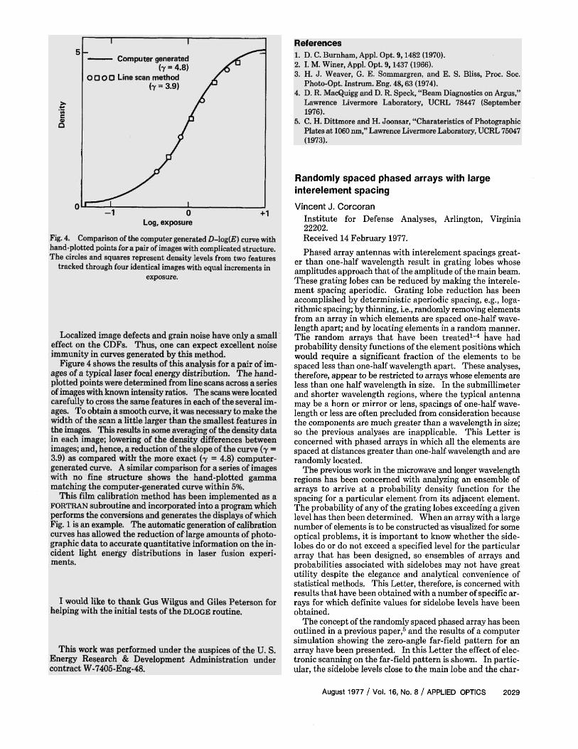
Institute for Defense Analyses, Arlington, Virginia 22202. Received 14 February 1977. Phased array antennas with interelement spacings great
er than one-half wavelength result in grating lobes whose amplitudes approach that of the amplitude of the main beam. These grating lobes can be reduced by making the interelement spacing aperiodic. Grating lobe reduction has been accomplished by deterministic aperiodic spacing, e.g., logarithmic spacing; by thinning, i.e., randomly removing elements from an array in which elements are spaced one-half wavelength apart; and by locating elements in a random manner. The random arrays that have been treated1–4 have had probability density functions of the element positions which would require a significant fraction of the elements to be spaced less than one-half wavelength apart. These analyses, therefore, appear to be restricted to arrays whose elements are less than one half wavelength in size. In the submillimeter and shorter wavelength regions, where the typical antenna may be a horn or mirror or lens, spacings of one-half Wavelength or less are often precluded from consideration because the components are much greater than a wavelength in size; so the previous analyses are inapplicable. This Letter is concerned with phased arrays in which all the elements are spaced at distances greater than one-half wavelength and are randomly located.
The previous work in the microwave and longer wavelength regions has been concerned with analyzing an ensemble of arrays to arrive at a probability density function for the spacing for a particular element from its adjacent element. The probability of any of the grating lobes exceeding a given level has then been determined. When an array with a large number of elements is to be constructed as visualized for some optical problems, it is important to know whether the side-lobes do or do not exceed a specified level for the particular array that has been designed, so ensembles of arrays and probabilities associated with sidelobes may not have great utility despite the elegance and analytical convenience of statistical methods. This Letter, therefore, is concerned with results that have been obtained with a number of specific arrays for which definite values for sidelobe levels have been obtained.
The concept of the randomly spaced phased array has been outlined in a previous paper,5 and the results of a computer simulation showing the zero-angle far-field pattern for an array have been presented. In this Letter the effect of electronic scanning on the far-field pattern is shown. In particular, the sidelobe levels close to the main lobe and the char-
August 1977 / Vol. 16, No. 8 / APPLIED OPTICS 2029

Fig. 2. Computer run for far-field pattern of a ninety-one element symmetrical array, with unequal spacing between elements, which
is electronically scanned with ΘO = 1 mrad.
Fig. 1. Illustration of the far field; (a) group pattern; (b) unit pattern; and (c) resultant pattern, which is the product of the group pattern and the unit pattern for an array whose elements are spaced a distance
d apart and whose apertures are b.
acteristics of the main lobe are considered. Also, the difference in the approach to designing random arrays vs deterministic or pseudo random arrays is discussed.
The far-field pattern of an array antenna is given by the Fourier transform of the aperture pattern. The result for the case where the elements whose apertures have a linear dimension b are equally spaced a distance d apart is illustrated in Fig. 1. The resultant pattern is seen to be the product of a group pattern, which will also be called a grating pattern, and a unit pattern, which will also be called the aperture pattern.
The specific type of array to be considered in this Letter is an array in which the elements are symmetrical about the center of the array and in which an element may be located at the center. In this case the far-field intensity is given by
where λ is the wavelength, b is the aperture width, θ is the angle from the normal to the array, and dn is the distance from the center of array to the center of the nth aperture. The first term in this equation is the aperture pattern, and the second term is the grating pattern for the case when an element is located at the origin. When there is no term at the origin, then the grating function reduces to
The equation for the far-field pattern of an antenna was programmed and run to obtain information on the perfor
mance of the array. The results for the zero-angle far-field pattern have been previously given.5
The next step was to attempt to scan the array. The scanning is accomplished by digitally selecting the angular position of the desired maximum and adjusting the phases of the symmetrical elements so they interfere as desired. This technique is accomplished by choosing the phase of one element of the nth pair to be øn1 = – k dn sinθ and the other element to be øn2 = + k dn sinθ. The intensity is then a maximum at 0.
The result of scanning the array with the computer program is shown in Fig. 2 for θ = 10–3 rad. In each case the grating lobe level remains essentially as it is for θ = 0 modified by the unit pattern. In addition, it should be observed that close to the main beam the energy is essentially zero on the linear scale that has been used for Fig. 2.
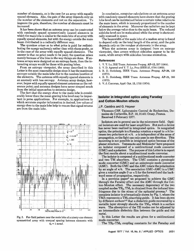
If the scale is expanded to examine the details of the energy distribution close to the main lobe, the results shown in Fig. 3 are obtained. For each scan angle considered, the grating lobe level is 20-30 dB below the main beam. For a random array with ninety-one elements, the mean grating lobe level is calculated to be 19.6 dB below the main lobe. This is an example where the values for a specific array differ from the mean value obtained by averaging over an ensemble of arrays. This difference between what is actually achieved and the value obtained by an ensemble average can be important in some applications, such as high resolution angular tracking using a phased array.
The low value of the radiation at angles close to the main beam can be explained by the fact that each symmetrical pair of antenna elements produces energy in the main lobe and at harmonics of the inverse of the separation of the pair. The pair with the widest separation from its neighbors produces harmonic energy closest to the main beam. All other pairs produce energy at greater distances from the main beam. Hence, all the grating lobe energy is outside some minimum angle in this idealized case. Some energy is available in this region close to the main lobe due to the fact that each antenna pair actually distributes some of its energy over all angles.
When these computer calculations are carried out for a number of arrays, the beamwidth of the main lobe is found to depend only on the separation of the two elements that are most distant from the center. It is also independent of the
2030 APPLIED OPTICS / Vol. 16, No. 8 / August 1977
number of elements, as is the case for an array with equally spaced elements. Also, the gain of the array depends only on the number of the elements and not on the separation. To improve the gain, therefore, the number of elements must be increased.
It has been shown that an antenna array can be constructed with randomly spaced symmetrically located elements in which the main lobe is similar to the main lobe of an array with equally spaced elements, but with the energy outside the main beam distributed in a radically different way.
The question arises as to what price is paid for redistributing the energy uniformly rather than with sharp peaks, as in the case of the array with equally spaced elements. The answer is that no price needs to be paid; the question arises merely because of the bias in the way things are done. If antenna arrays were designed on an entropy basis, then the interesting arrays would be those with grating lobes.
From an entropy viewpoint, the array described in this Letter is the most reasonable design since it has the maximum entropy outside the main lobe due to the random location of the elements. The antenna with equally spaced elements is an anomaly with less entropy. Antenna array design, however, began with equally spaced element antennas as the reference point; and antenna designs have never strayed much from the initial approaches to antenna design.
The fact that the energy close to the main lobe is considerably lower than the mean grating lobe level may be important in some applications. For example, in applications in which accurate angular information is desired, low values of energy close to the main lobe help to ensure that signal returns are from the main lobe.
Fig. 3. Far-field pattern near the main lobe of a ninety-one element symmetrical array with unequal spacing between elements with
θ0 = 1 mrad.
In conclusion, computer calculations on an antenna array with randomly spaced elements have shown that the grating lobe level can be maintained below a certain value relative to the main beam, which is inversely proportional to the number of elements in the array. Moreover the radiation can be kept below the average value close to the main beam. The reduced sidelobe level can be maintained while the array is electronically scanned in space.
The beamwidth of the main lobe of a random array is found to depend only on the total length of the array, and the gain depends only on the number of elements in the array.
When the antenna array is designed from an entropy viewpoint, then arrays without sidelobes appear to be the norm, while arrays with sidelobes become anomalous.
References 1. Y. T. Lo, IRE Trans. Antennas Propag. AP-12, 257 (1964). 2. V. D. Agrawal and Y. T. Lo, Proc IEEE 57, 1764 (1969). 3. B. D. Steinberg, IEEE Trans. Antennas Propag. AP-20, 129
(1972). 4. B. D. Steinberg, IEEE Trans. Antennas Propag. AP-21, 366
(1973). 5. V. J. Corcoran, Appl. Opt. 13, 1755 (1974).
August 1977 / Vol. 16, No. 8 / APPLIED OPTICS 2031