rapid and reconfigurable tooling methods for …cats-fs.rpi.edu/tves07presentations/tves 07...
TRANSCRIPT

CATS is a NYSTAR-Designated Center for Advanced Technology
Rapid and Reconfigurable Tooling Methods for Manufacturing Large-Scale Plastic and Composite Parts
By
Daniel F. Walczyk, PhD, PE
Associate Professor
Department of Mechanical, Aerospace & Nuclear Engineering

Outline of Talk
• Motivation• Profiled Edge Laminae (PEL) Tooling
– Case study: Thermoforming mold
• Reconfigurable Pin-type (RPT) Tooling– Case study: Active forming of advanced
composites
• Concluding Remarks

Motivation – Rapid Tooling
• In manufacturing, tooling refers to a a die or a mold. – Die – Cavity (2-piece) or shape used in
deformation processes in which the starting material is a ductile solid (commonly metal) which is deformed to shape the part (e.g., sheet metal forming die).
– Mold – Cavity or shape used in casting, molding, and other manufacturing processes in which the starting material is a heated liquid or semifluid (e.g., plastic injection mold).

Motivation – Rapid Tooling
• The primary method of tooling fabrication in industry is CNC (computer numerical control) machining a billet of material, which is referred to as a subtractive approach.
• Rapid Prototyping (RP) is “a special class of machine technology that quickly produces models and prototype parts from 3-D data using an additive approach to form the physical models.”
• Rapid Tooling (RT) means “tooling driven by RP.”
Source: Wohlers, T., www.wohlersassociates.com

Motivation – Subtractive vs. Additive
Subtractive Additive

Motivation – RT Niche• CNC machining of tooling is so prevalent within the
manufacturing industry because of easy-to-use equipment and software, rapid cycle times, unattended operation, and ability to machine hard materials.
• The niche that RT methods fill is providing enhanced tool capabilities such as complex geometry, conformal cooling/heating channels, multiple materials, functionally gradient materials, and embedded sensors.

Motivation – Current Limitations of RT
1. Most RT methods currently available are only suitable for manufacturing small- to medium-size components. One solution is Profiled Edge Laminae(PEL) Tooling.
2. RT (and CNC machining) still involves the creation of a permanent tool that must be stored and maintained. What if we could completely do away with permanent tooling altogether? One possible alternative is Reconfigurable Pin-Type Tooling.

PEL Tooling

Profiled Edge Laminated (PEL) Tooling
• Method developed and implemented with funding from NSF (5 years) and implemented with state and industrial funding from NYSERDA, Kintz Plastics (1 year)
• Thick layer tooling fabrication method• Each lamination has a profiled and beveled top
edge

PEL Tooling
• Laminations are stacked together vertically in an array
• Clamping bolt holes, conformal cooling/heating channels, unneeded thermal mass, sensor routing channels are cut simultaneously using AWJ or laser cutting along with top edge
• Laminations can be bonded together• Ideal for large-scale tools (automotive and
aerospace industries)Structural Supports
Forming Surface of Mold
Through Bolt or Conformal
Channel Holes
Cut-out Sections of Lamina

Similar Technology to PEL -Fast 4m™ Tooling
• Located in Dearborn, MI.• Laminae are first laser cut, CNC
machined, and bonded to previous layer.
• Tool thickness is checked constantly, so that slicing must be in real time.
• Adjacent laminae are bonded together using a proprietary high-temperature bonding process.
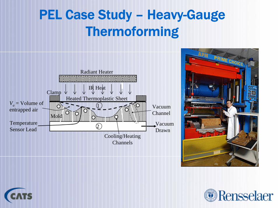
PEL Case Study – Heavy-Gauge Thermoforming
MoldVacuum Drawn
Vacuum Channel
Radiant Heater
IR Heat
Temperature Sensor Lead
1
2
Clamp
Va = Volume of entrapped air
Cooling/Heating Channels
Heated Thermoplastic Sheet

PEL Case Study – Test Part & Mold Design
• CRT Bezel for digital picture printing kiosk (e.g., in Walmart)– 38×270×347mm – 4.7 mm thick, Acrylic/PVC
blend
• Mold Design– Mold temperature = 60°C– Vacuum holes– 3 conformal cooling loops– 3 embedded thermocouples

PEL Case Study – Vacuum Channel Design
Outer
Inner
Middle
Top View of Mold
Scored vacuum channels in one lamina

PEL Case Study – Conformal Channel Design
Working Fluid
PEL Tool Surface
Sealant in between laminae and localized near channelConformal
Channel
Lamina
Three conformal channel loops
Localized sealing at lamina interfaces by pressurizing
with sealant
Eout
Ein
Est
Negligible
Ta(t)
Tm(t)
Tc & hc
D
lm
lp
W
Part
Mold
Conformal Channel
Channels designed using unit cell modeling approach

PEL Case Study – CAD Modeling of Mold
• Modeled with Solidworks• Profile, conformal channel
holes, bolt holes, vacuum channels, and sensor channels included.
• Stock lamina thickness used (1/8”, 1/4”, 3/8”, 1/2”, 1”)

PEL Case Study – Mold Fabrication
• Each lamina was AWJ cut on a 2-axis CNC machine based on CAD model
• Lamina were assembled with thermocouples and bolted together, and conformal loops were sealed
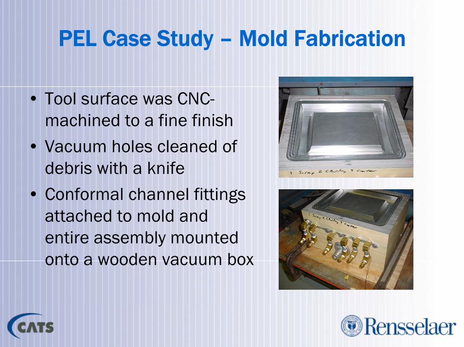
PEL Case Study – Mold Fabrication
• Tool surface was CNC-machined to a fine finish
• Vacuum holes cleaned of debris with a knife
• Conformal channel fittings attached to mold and entire assembly mounted onto a wooden vacuum box

PEL Case Study – Thermoforming Trials• Water temperature flowing through
all three conformal loops in the mold was set to 60°C.
• Flat plastic blank was heated with infrared heaters for 150 seconds until the plastic temperature was approximately 177°C.
• Once the part was formed by drawing vacuum of 0.8 bar, it was held in the mold for about 5 minutes to cool down.
• 10 quality parts were successfully formed

PEL Case Study – Temperature Sensor Measurements
58.00
60.00
62.00
64.00
66.00
68.00
70.00
0 100 200 300 400
Time (sec)
Mol
d Te
mpe
ratu
re (d
egC
)
Outer
Middle
Inner
Outer
Inner
Middle

RPT Tooling

Commercial RPT Systems
Cyril Bath, Inc. Tool (co-developed by NG and MIT) – 2 systems in use
Huntsman Advanced Materials Tool (one-of-a-kind)
North Sails Tool for Composite Sails with scissor-type mechanisms (one-of-a-kind)

RPT Case Study – Composites Forming
• Cyril Bath’s discrete bed-of-pins tool was designed for stretch forming of aircraft body panels (Northrop Grumman Corp.)
• Each pin is actuated with a motor-driven leadscrew• Could bed-of-pins tooling be applied to composites
forming to increase the range of parts that are formable?
• Incremental forming of composite parts using a bed-of-pins tool (sponsored by NSF & Northrop Grumman)

• Heat is required to reduce the viscosity of the epoxy matrix before fiber movement can occur
• Force is required to slide the fibers and to conform the softened composite material to the mold
• Active control over the mold shape (i.e., mold shape is changed incrementally from flat shape to final part shape during the forming process) is required.
RPT Case Study – Manufacturing Requirements

RPT Case Study – Incremental Forming using Active Tooling
• Basic Process based on Double Diaphragm Forming (DDF) & Low-Powered Conductive Heating over a bed-of-pins tool that actively changes shape during process.
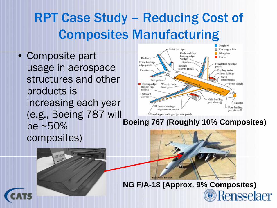
RPT Case Study – Reducing Cost of Composites Manufacturing
• Composite part usage in aerospace structures and other products is increasing each year (e.g., Boeing 787 will be ~50% composites)
Boeing 767 (Roughly 10% Composites)
NG F/A-18 (Approx. 9% Composites)

RPT Case Study – Northrop Grumman’s DDF Capabilities (El Segundo, CA)

Advantages of Double DiaphgramForming (DDF)
• Traditional hand layup of composite pre-preg layers into multi-layer parts is too labor-intensive and automation is too expensive. DDF is much quicker and lower cost than either method.

RPT Case Study - Shape Change Control with Active Bed-of-Pins Tooling
• Simple Proportional Control of Pin Positions
• Sequential forming, i.e., shape is developed about the ellipse short axis first, followed by a bend about the ellipse long axis (Short-Long shown).

RPT Case Study - Example Forming Sequence with an 8×12 Bed-of-Pins Tool

RPT Case Study – Forming Hardware & Software
Pin Control Interface
Inner and Outer Diaphragm Clamping Frames
Formed Composite Lay-up
Temperature Readout
Inner Vacuum Supply Line
9-Zone Heating Blanket

CAD Representation of Part
Simulation of Forming
Shape Change
Sequence Planning
Data File Containing Pin Height
Information for Tool Software
Pin Placementfrom File
Uniform Compression of the Interpolator is Assumed
RPT Case Study – Virtual Part Shape Generation
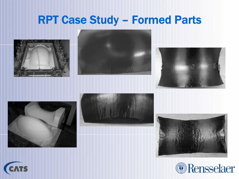
RPT Case Study – Formed Parts

Concluding Thoughts