rapid conceptual design evaluation using a virtual product model
TRANSCRIPT
Pergamon PII:S0952-1976(96)00035-8
EngngApplic. Artif lntelL Vol. 9, No. 4, pp. 439-451, 1996 Copyright O 1996 Elsevier Science Lid
Printed in Great Britain. All rights reserved 0952-1976/96 $15.00 + 0.00
Contributed Paper
Rapid Conceptual Design Evaluation Using a Virtual Product Model
MARK J. CLAYTON Texas A&M University, U.S.A.
JOHN C. KUNZ Stanford University, U.S.A.
MARTIN A. FISCHER Stanford University, U.S.A.
(Received December 1995; in revised form March 1996)
This paper presents an architecture and test results for a computer-based system for assisting the conceptual phase of building design. The system uses 3D CAD to represent a graphic model of the design, and it uses A1 symbolic models of the geometric forms, intended functions and computed and assigned behaviors of the design. The system uses AI symbolic reasoning methods to analyze design behavior and compare predicted behavior with intended function. The Semantic Modeling Extension (SME) system incorporates a virtual product model: a small but extendible set of classes that define generic forms, functions and behaviors of facilities. After drawing a design using 3D CAD, a designer interactively creates interpretation objects as instances of the virtual product model. The interpretation objects express the meaning of the graphic representation with respect to a particular engineering issue, such as energy use or cost. The interpretation represents geometric and topological attributes of the features for use by automated design analysis tools. Interpretation objects unite support for graphically-oriented design thinking with support for automated symbolic reasoning. The paper includes an example building design scenario using the software prototype, illustrating how interpretation of the geometric model produces a symbolic model and supports multiple and changing analyses and evaluations during design. Students and practising engineers have tested the system in classes and workshops. Copyright © 1996 Elsevier Science Ltd
Keywords: Behavior, CAD, evaluation, SME, virtual product model.
1. INTRODUCTION
Design involves creating graphic models of the artifact, and cognitive models of design intent and content. Researchers and practitioners have long tried to introduce automation into the design process to improve the quality and consistency of design. The challenge in automating design is to introduce automation in a way that makes design faster and more effective, and stimulates rather than hinders designers' creativity and freedom. Symbolic models describe the cognitive models, make their contents explicit
Correspondence should be sent to: John C. Kunz, Center for Integrated Facility Engineering, Stanford University, Stanford, CA 94305-4020, U.S.A. Email: [email protected].
and support design automation. A fundamental problem is to assign design intent and content to graphic elements. This problem is more difficult because design is inherently an iterative process, and graphic and cognitive models need to evolve, be kept consistent, and support each other.
This paper presents the Semantic Modeling Extension (SME). SME distinguishes drawing a design from assigning meaning to a graphic form. The SME user interprets graphic forms to identify their symbolic form, functions and behaviors. The explicit interpretation approach used by SME builds on the rich and well-established tradition of graphic thinking for design. The designer interactively interprets the semantics of the graphic representations created during design explorations.
439
440 MARK J. CLAYTON et al.: VIRTUAL PRODUCT MODEL
A virtual product model provides a foundation for the creation of computer-aided design (CAD) systems that allow designers to work in a graphic environment yet obtain many benefits of automated design evaluation and predic- tion software. A virtual product model explicitly and separately represents the design form, function and behav- ior. The designer can independently and explicitly manipulate the form and its functions. A virtual product model avoids the necessity for a rigidly defined component library, yet provides the designer with the benefits of automated critiques integrated with a CAD system. By providing easy-to-use tools to link graphic representations of the building form with symbolic representations of form, function and behavior, a virtual product model provides an extensible, flexible environment to support exploratory design.
In contrast, the STEP model explicitly represents form in great detail, but it does not explicitly represent function and behavior, t Like a conventional product model, SME addresses the goal of support for information exchange among multiple applications. Unlike a conventional product model, SME does not employ a central, comprehensive product representation defining complex interrelationships among components. In support of conceptual design, the virtual product model defines just enough detail about form to allow associated reasoning methods to make predictions about behavior.
2. RELATED RESEARCH
The evolution of computer graphics into true computer- aided design systems depends upon formalizing and representing relevant design semantics in computer models. In the commercial world, the approach has generally been to encode meaning into drawings by use of drawing layers. Researchers have generally adopted a component-oriented approach. Virtual product modeling presents an alternative method.
2.1. Layer paradigm
Virtually all commercial CAD systems provide the functionality to assign graphic entities to "layers", analo- gous to the overlays in pin-bar drafting. As layers can be made visible or invisible, the user can control the visual portrayal of the drawing by toggling layers on and off and moving entities from one layer to another. Layers provide a means to collect entities with related meanings, often by professional discipline, such as all structural elements onto one layer, all architectural elements onto another, and all mechanical elements onto a third layer.
Unfortunately, the layer paradigm has several critical limitations. A layer name can only provide a semantic identifier to a collection of entities. The layering scheme cannot explicitly represent the semantic content of individ- ual entities on the layer. The use of complex primitives, known variously as blocks, cells or symbols, provides a means for naming individual entities. A more serious limitation is that an entity may exist on only one layer.
Designers rarely decompose building into collections of entities with single, distinct meanings. For example, a wall may appropriately concern architectural, structural and mechanical issues, but it can appear on only one layer. Work-arounds can address this limitation, but none of them are fully satisfying. The layer paradigm, while appropriate to automating overlay drafting, is inappropriate to support detailed analysis of functions and behaviors required to evaluate designs of buildings. Nevertheless, layer-based representations of building semantics are widely used in commercial CAD tools, such as ASG and LightCAD.
2.2. Component paradigm
The layer paradigm has been rejected by researchers, generally in favor of a component-oriented approach. In this view, a building is decomposable into its parts, each of which has pre-determined semantic content. Research using a component approach focuses on the correct and compre- hensive definition of components so that they may support a variety of design purposes. The KAAD system, for example, provides components for the design of hospital suites that may be viewed at several degrees of abstraction and analyzed within several evaluative contexts. 2
Product models, e.g. STEP, assume an explicit repre- sentation of components. Researchers devote attention to the development of specialization (kind-of or is-a) hier- archies and part-of hierarchies and to the definition of attributes and relations among classes and instances. Much of this research blends implementation methods using relational databases, object-orientation, and frame-based semantic networks. Many interesting projects have pro- posed frameworks for expressing the meaning of design components within a single reasoning context or across several reasoning c o n t e x t s . 3'4
Numerous research prototypes of integrated CAD sys- tems have been built. 5'6 Typically, these systems manipulate a database, use rules, apply constraints, or use some computer science approach to synthesize graphic forms from a statement of function. These approaches tightly bind semantic values to the graphic representation. The design process becomes a process of component selection. There remains an uneasiness that such computer-synthesis meth- ods diminish the creativity and delight inherent in traditional drawing-based design methods.
The drawback of the component paradigm is that the comprehensive definition of component semantics is an extremely difficult task. It requires that the researchers or software developers preparing the object hierarchies must be fluent in many diverse design disciplines, and must define terminology for design attributes that can be accepted across disciplines. There is a tendency toward a profusion of attributes of each object to accommodate any conceivable use of the object in a design project. Due to designers' well- known predilection for clever, or even perverse, use of design objects, one might speculate that real designers would take pleasure in breaking whatever system of component semantics developers devise.
The component approach perhaps suffers from an over-
MARK J. CLAYTON et al.: VIRTUAL PRODUCT MODEL 441
emphasis upon the physical and non-physical objects that compose a building, without careful consideration of the purpose of those objects.
2.3. Modularized design environments
Both the layer-based approach and the component- oriented approach provide predefined, rather inflexible semantic representations. At some point before designers can begin sketching and portraying design ideas, the semantic content of the project must be prescribed, either in a layer structure or in the attributes of a component representation. Some researchers have recognized the limitations inherent in predefined design semantics. East- man describes a building modeling system that can be dynamically composed for the purpose of a particular project. 7 An engineering environment could consist of application modules that communicate via messaging using an object-oriented operating system. An engineer could collect preferred documentation and evaluation tools into a virtual product model.
The virtual product model idea differs from the compo- nent-oriented paradigm because it creates relationships among explicitly represented semantic and graphic entities, rather than unifying the two. The semantics of each entity are considered only within a reasoning context that defines function and behavior representations. The architect or engineer interactively identifies features within an inter- pretation and thereby specifies semantics. During the course of the building design effort, new entities may be added to the design, new semantics may be added to entities, and old semantics may be removed. The product model is intan- gible, rapidly reconfigurable, and adaptive to the needs that may arise.
3. ARCHITECTURE OF THE SME VIRTUAL PRODUCT MODEL
This section discusses the representation of form, func- tion and behavior and describes the linking of graphic and symbolic models through interpretations. Form, function and behavior are represented explicitly with declarative, symbolic object-oriented models. An issue of a design, e.g. space or cost, describes a particular form and its associated functions and behaviors.
3.1. Form In SME, f o r m is defined as the geometry of the design.
Form is what architects draw in plan, section, elevation and perspective. Form describes physical components, such as a wall or column, or abstract entities, such as a space or region. Form references associated function and behavior. Form is naturally represented and manipulated using computer graphics techniques. Examples of form entities are planes, boxes and complex 3D shapes. Forms are the result of the synthesis step in Asimow's design cycle, s and "follow" from function.
3.2. Function
Synonyms for funct ion include requirements, needs, intents and design objectives. Functions express desires for the building: the client desires a space to accommodate a cyclotron; the client desires a pleasing exterior finish; or the client desires construction within a stated budget. Clients specify some functions; codes and industry practice deter- mine others; needs and preferences of contractors, suppliers, operators and users specify others. Functions are the result of the Formulate step (see Fig. 5) and originate from a desire to address a design objective. A design will have different classes of functions, such as providing spaces specified in an architectural program, energy use and cost objectives.
3.3. Behavior
Behavior is the expected performance of the design within a particular design situation, concerning a particular engineering issue. Behavior is typically derived from the form model by a process of prediction. 2 Behaviors normally map in some well-defined way to the functions to support evaluation of the design. Conseqt~ently, much of the research literature uses the two terms interchangeably. However, others, e.g. Luth et al., 9 make the distinction between desired performance (function) and predicted performance (behavior).
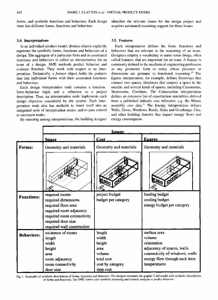
Behaviors are measurable, computable or observable attributes of design forms, such as the examples shown in Fig. 1. Many authors limit behavior to those attributes that are computed (e.g. volume, cost), assigning to form those geometric attributes that are assigned (e.g. length, width). Although the definition is arbitrary, both assigned and predicted values are grouped in SME under the generic class of behaviors. This convention leads to a very simple definition of evaluation: it compares behaviors with func- tions.
SME represents a number of behaviors. Length is the larger of the two horizontal dimensions of the bounding box of a solid. Width is the smaller of the two. Height is the vertical dimension of the bounding box. Volume is comput- able for any solid. Area is defined with respect to various planes. Connectivity is a behavior that serves as a base class to both supported-by behavior and door-room connectivity. These basic geometric and topological behaviors form the foundation for more complex, issue-centered behaviors.
Behaviors may be very simple, such as the area of a form, or much more complex and subtle, such as the energy flow through a wall in a particular climate at various time intervals. Each issue concerns a particular collection of forms, functions and related behaviors. The spatial issue concerns areas and adjacencies of rooms, connectivity of doors to rooms, and sizes of doors. The cost issue concerns the quantities of various elements. The scheduling issue defines construction activities and construction dates as behaviors of the form. The energy issue concerns con- vective, conductive and solar radiation energy flows through various features.
Figure 1 shows examples for symbolic and graphic
442 MARK J. CLAYTON et al.: VIRTUAL PRODUCT MODEL
forms, and symbolic functions and behaviors. Each design identifies the relevant issues for the design project and issue has different forms, functions and behaviors, acquires automated reasoning support for those issues.
3.4. Interpretations In an individual product model, distinct objects explicitly
represent the symbolic forms, functions and behaviors of a design. The aggregate of a particular form and its associated functions and behaviors is called an interpretation for an issue of a design. SME methods predict behavior and evaluate function. They work with respect to an inter- pretation. Technically, a feature object holds the pointers that link individual forms with their associated functions and behaviors.
Each design interpretation node contains a function- form-behavior triple and a reference to a project description. Thus, an interpretation node implements each design objective considered by the system. Each inter- pretation node also has methods to insert itself into an integrated suite of interpretation nodes, and to pass control to successor nodes.
By selecting among interpretations, the building designer
3.5. Features Each interpretation defines the form, functions and
behaviors that are relevant to the reasoning of an issue. Designers employ a vocabulary to name some things, often called features, that are important for an issue. A feature is commonly defined in the mechanical engineering profession as any geometric form or entity whose presence or dimensions are germane to functional reasoning. '° The Egress interpretation, for example, defines Doorways that connect two spaces, Entrances that connect a space to the outside, and several kinds of spaces, including Classrooms, Storerooms, Corridors. The Construction interpretation defines an extensive list of construction assemblies derived from a published industry cost reference, e.g. the Means assembly cost data." The Energy interpretation defines Walls, Doors, Windows, Roofs, Slabs and Overhangs, Fins, and other building features that impact energy flows and energy consumption.
Forms:
Functions:
Behaviors:
Sna¢¢
Geometry and materials
.... j j
required rooms
required dimensions
required floor area required room adjacency
required room connectivity
required door size
required wall construction
existence o f rooms
l ~ u e s ;
Geometry and materials
project budget
budget per category
length length
width height
a r e a
room adjacency room connectivity
door size
width
height area volume
total cost
cost by category item cost
Ener~v
Geometry and materials
heating budget
cooling budget
energy budget per category
surface area volume
orientation
adjacency o f spaces, walls connectivity o f windows, walls
energy flow through each item temperatures
Fig. I. Examples of symbolic descriptions of forms, functions and behaviors. The designer annotates the graphic CAD model with symbolic descriptions of forms and functions. The SME system uses symbolic reasoning and numeric analysis to predict behavior.
MARK J. CLAYTON et al•: VIRTUAL PRODUCT MODEL 443
3.6. Interpretation manager
An interpretation manager supports dynamic schema extension. This manager object maintains the list of loaded interpretations, and allows the user to add new inter- pretations and to delete unneeded interpretations. The interpretation manager also supports functionality that ranges across interpretations. SME supports Boolean opera- tions on the feature lists of interpretations, and query of a graphic entity for its membership among multiple inter- pretations. Refinements to the interpretation manager could implement consistency checks among non-graphic attri- butes of features across interpretations.
The interpretation manager links the virtual product modeling with a commercial CAD system.
4. SCENARIO
This section discusses how SME fits into the design process and supports creative graphic design and partial design automation.
Consider the following case example: an architect needs to design a suite of rooms for a hospital. This scenario is built on observations of a recently-completed building project. The architect has a top-level objective: design spaces to accommodate a cyclotron to provide radioisotopes for a radiology lab. The architect's role is to specify the spaces, enclosures and equipment in enough detail to permit construction, while meeting budgetary and functional
requirements and aesthetic goals• The hospital administrator has given the architect a rough
estimate of the size of the new hospital addition in terms of overall floor area, approximate budget, and a time frame for the project. The administrator also provides contacts at the cyclotron manufacturer, and brochures describing the equipment.
4.1. Initial drawings
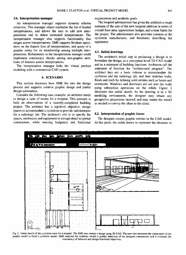
The architect's initial step in producing a design is to formulate the design, as a conceptual-level 3D CAD model and as a statement of building functions. Architects call the statement of function the "architectural program". The architect lays out a basic volume to accommodate the cyclotron and the radiology lab, and then sketches walls, floors and roofs by defining solid entities such as boxes and extrusions. Windows and doorways are cut into the walls using subtraction operations on the solids. Figure 2 illustrates this initial sketch. As the drawing is in a 3D modeling environment, the designer may obtain any perspective projections desired~ and may render the model as needed to convey the ideas to the client.
4.2. Interpretation of graphic forms
The designer creates graphic entities in the CAD model. At this point, the solids drawn to represent the elements in
I•
7 K It,,
. . . . i
-II
41
- ~ . | 1
L Fig. 2. Initial sketch of the cyclotron room for a hospital. The SME user creates a design using 3D CAD. The user then interprets the components of the graphic model to build a symbolic model. SME analyzes the symbolic model to predict behaviors of the designed components, and it evaluates the
consistency of behavior and design functional objectives.
444 MARK J. CLAYTON et al.: VIRTUAL PRODUCT MODEL
the design have no explicitly expressed semantics, and automated evaluation is thus not possible. In the process of interpretation, the designer creates symbolic entities to describe each form, and links corresponding graphic and symbolic form entities. The symbolic form objects refer- ence symbolic functions that describe the design intent of including the forms. Finally, forms have associated pre- dicted behaviors.
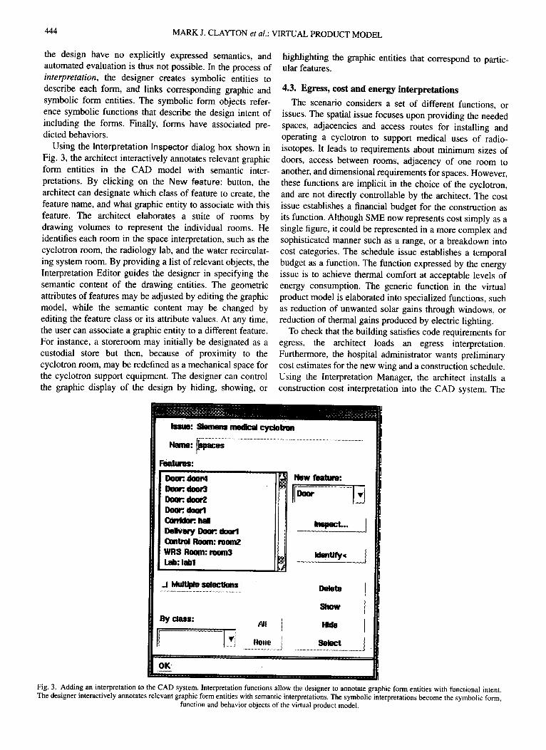
Using the Interpretation Inspector dialog box shown in Fig. 3, the architect interactively annotates relevant graphic form entities in the CAD model with semantic inter- pretations. By clicking on the New feature: button, the architect can designate which class of feature to create, the feature name, and what graphic entity to associate with this feature. The architect elaborates a suite of rooms by drawing volumes to represent the individual rooms. He identifies each room in the space interpretation, such as the cyclotron room, the radiology lab, and the water recirculat- ing system room. By providing a list of relevant objects, the Interpretation Editor guides the designer in specifying the semantic content of the drawing entities. The geometric attributes of features may be adjusted by editing the graphic model, while the semantic content may be changed by editing the feature class or its attribute values. At any time, the user can associate a graphic entity to a different feature. For instance, a storeroom may initially be designated as a custodial store but then, because of proximity to the cyclotron room, may be redefined as a mechanical space for the cyclotron support equipment. The designer can control the graphic display of the design by hiding, showing, or
highlighting the graphic entities that correspond to partic- ular features.
4.3. Egress, cost and energy interpretations
The scenario considers a set of different functions, or issues. The spatial issue focuses upon providing the needed spaces, adjacencies and access routes for installing and operating a cyclotron to support medical uses of radio- isotopes. It leads to requirements about minimum sizes of doors, access between rooms, adjacency of one room to another, and dimensional requirements for spaces. However, these functions are implicit in the choice of the cyclotron, and are not directly controllable by the architect. The cost issue establishes a financial budget for the construction as its function. Although SME now represents cost simply as a single figure, it could be represented in a more complex and sophisticated manner such as a range, or a breakdown into cost categories. The schedule issue establishes a temporal budget as a function. The function expressed by the energy issue is to achieve thermal comfort at acceptable levels of energy consumption. The generic function in the virtual product model is elaborated into specialized functions, such as reduction of unwanted solar gains through windows, or reduction of thermal gains produced by electric lighting.
To check that the building satisfies code requirements for egress, the architect loads an egress interpretation. Furthermore, the hospital administrator wants preliminary cost estimates for the new wing and a construction schedule. Using the Interpretation Manager, the architect installs a construction cost interpretation into the CAD system. The
i Immo: 81ms'ions n ~ cy, c ~ Nwnm" ~ ........................................................................................................................
Foaturos: ° " ' ' " "
ooo,: , doo,, , t - Doer: ~ ~ aoorl ~ h a l l I ~ Door:. nooa 1 O m t ~ Room: room2 ~lS Room: roolld khmtify,t / I ~I~: lab1 J
I[ooo,. Insl0oct...
_l ~ $OlOCtioos
By class: ,all i +
If I" ........ OKI
snow I
Fig+ 3. Adding an interpretation to the CAD system. Interpretation functions allow the designer to annotate graphic form entities with functional intent. The designer interactively annotates relevant graphic form entities with semantic interpretations. The symbolic interpretations become the symbolic form,
function and behavior objects of the virtual product model.
MARK J. CLAYTON et al.: VIRTUAL PRODUCT MODEL 445
architect creates solid CAD objects to represent the footings, HVAC units, lighting systems and building equipment. During preliminary design, the components are drawn abstractly. Using the Interpretation Editor, the architect designates the meaning of each CAD object within the context of the construction interpretation by identifying construction features. The construction features refer to items in an assembly-based estimating database such as spread footings, block walls and drywall partitions. ~ The architect also types in values for the cost budget and the project time constraints.
To address the energy-consumption issue, the architect loads another interpretation for examining the energy consumption of a building. Once again, he identifies the features of the building, this time considering energy use. These include the exterior walls, the windows, the roof, the lighting systems, and other feature classes. The designer has already drawn most, if not all, of these features; they need only be annotated as features in the energy interpretation, and assigned appropriate semantic values. The architect designates the climate for the project and a set of energy- consumption objectives.
4.4. Design critique
Having annotated graphic forms with their functional intents, the architect now invokes an automated prediction of the behavior of the design and critiques its behavior with respect to functions. In a few seconds a reasoning module analyzes the design and evaluates its sufficiency in accom- modating a cyclotron room and a radiology lab. It examines
the dimensions of the rooms, vertical clearances, accessi- bility for installation, maintenance and operational requirements, and adjacency of related spaces. Another reasoning module provides the evaluation that the design meets the relevant code provisions for egress by examining the size and connectivity of rooms and doors in the egress interpretation. A construction evaluation tool provides a cost estimate and a preliminary construction schedule. In a few more seconds another tool evaluates the design regarding its predicted consumption of energy.
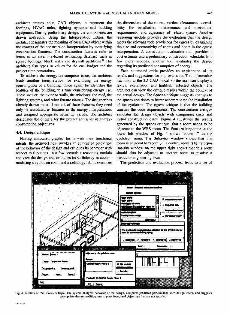
Each automated critic provides an explanation of its results and suggestions for improvements. This information has links to the 3D CAD model so the user can display a textual explanation and highlight affected objects. The architect can view the critique results within the context of the actual design. The Spaces critique suggests changes to the spaces and doors to better accommodate the installation of the cyclotron. The egress critique is that the building satisfies the code requirements. The construction critique annotates the design objects with component costs and initial construction dates. Figure 4 illustrates the results generated by the spaces critique, that a room needs to be adjacent to the WRS room. The Feature Inspector in the lower left window of Fig. 4 shows "room 1" as the cyclotron room. The Behavior window shows that this room is adjacent to "room 3", a control room. The Critique Results window on the upper right shows that this room should also be adjacent to another room to resolve a particular engineering issue.
The prediction and evaluation process leads to a set of
I m
~m:. Ebm~ 1
Qms: C~lwnn Roem
~ . j Him j .mtJ
Tho ~ ~ ~ m memm ~ uw wna ~ re"
~ Repine
l l a m w ~ o , i
Remm: I ' ~ I~mm:mm~ 3 I I~ UPW 4Mm
| . . . . .
I ~ d u m : ~ ROom: mewl 1
oK j ~ i
Fig. 4. Results of the Spaces critique. The system analyzes behavior of the design, compares predicted performance with design intent, and suggests appropriate design modifications to meet functional objectives that are not satisfied.
446 MARK J. CLAYTON et al.: VIRTUAL PRODUCT MODEL
suggestions about design conflicts. The architect chooses one or more conflicts to resolve, changes the form appropriately, and then invokes the prediction and critique process again to check that the introduced change has the desired effect, and to identify any unintended adverse consequences of the change. Changes to the graphic form may include drawing new objects, changing old objects, and re-interpreting the semantic functions of graphic entities. Most of the work is in editing the form of the building using the graphic editing tools.
4.5. Presentation
The interpretation and initial prediction and evaluation process takes perhaps an hour, including some iterative design of the cyclotron facilities and experimentation with different wall constructions to study their effects upon energy consumption, construction cost and schedule. The architect now has preliminary descriptions of the building's appearance, spatial layout, code conformance, construction cost, construction schedule and energy consumption to show the client. Each of the critiques is available to the user as an annotation of the 3D graphic model.
The architect and hospital administrator examine the issues together. By hiding the graphic model related to some interpretations and showing the graphics related to others, the architect and administrator can focus upon a single interpretation or combinations of interpretations. The administrator expresses some concern with the construction cost, but larger concern with the operating cost. She suggests brick exterior walls to provide a more pleasant, less utilitarian image for the new wing. In addition, she informs the architect that the hospital has begun discussing the purchase of the cyclotron from another manufacturer, and that she needs to compare the fully installed costs for each cyclotron option. She would like to study a design that allows the hospital to defer the selection of the cyclotron until after completion of the building.
4.6. Iteration with new information
The architect refines the design based upon the instruc- tions from the client. He obtains another critiquing tool from the second cyclotron manufacturer, perhaps down- loading it across a wide-area network, and loads it into the SME environment. He adjusts the room dimensions and access routes and builds a new interpretation to address the new issue of the second cyclotron manufacturer. In the hope of reducing operating costs, the architect inserts skylights in the lab space to provide natural lighting and reduce lighting- based energy consumption. He adds these new graphic entities to the construction and energy interpretations.
The architect uses automated critiques of the design to explore alternatives and balance the various issues. By carefully adjusting the dimensions of the cyclotron room and lab space, the architect achieves a design that satisfies both cyclotron alternatives. He explores the cost and energy impact of changing the exterior walls to brick construction and adding the skylights to the lab space, by examining the results of the construction and energy evaluation tools. The
critiques of each alternative provide a documented trail of the evolution of the design, and guidance toward improving performance.
At the end of the day, the architect has studied several design alternatives and produced accurate comparative evaluations of the alternatives and convincing visual- izations.
5. ANALYSIS OF THE SCENARIO
The scenario describes a believable design process and computer tools that support that process. The SME prototype provides an environment that automates some parts of the design process. It partially automates the behavior prediction and evaluation. It considers multiple issues in design. It provides mechanisms for accommodat- ing changing information needs as a project progresses. It integrates graphic thinking and symbolic analysis, allowing for consideration of the design in both modes.
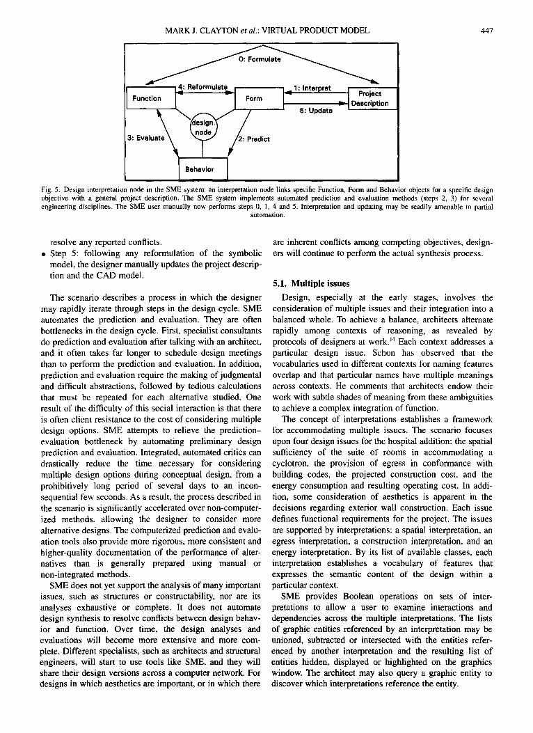
Design involves an iterative cycle of activities in which a design idea is formulated in response to requirements and tested for sufficiency to those requirements. Asimow 8 describes these activities as "analysis", in which the design requirements are formulated from a study of a problematic situation, synthesis, in which alternative solutions to the problem are conceived and documented, and evaluation, in which the solutions are tested for predicted performance and judged for suitability and optimality. SME assumes a slightly refined description of the design process. Figure 5, based on Refs 12 and 13 shows a design interpretation node in the SME system for one issue of one engineering discipline. Each design interpretation node supports a particular functional issue, such as cost estimation, energy use or building egress. The user and SME together perform the steps shown in Fig. 5:
• Step 0: the SME user describes intended functions of the design and creates a project description. Normally, the project description includes a CAD model, the archi- tectural program, and other documentation such as a schedule and references to parts in a component pricing catalog. In the SME system, the user creates a CAD model using a small set of 3D CAD primitives defined in the AutoCAD AME system.
• Step 1: the user manually "interprets" the project description, or identifies 3D objects in the CAD model as symbolic forms (e.g. doors, corridors) that are relevant to the particular issue. This interpretation process creates a symbolic model of the design.
• Step 2: SME methods automatically compute the pre- dicted behavior of form entities.
• Step 3: SME methods, called "critics", automatically compare the consistency of the predicted behavior with the intended function. SME critics now compute and check construction cost, egress, energy use and archi- tectural space use.
• Step 4: following an evaluation, the user can manually change the symbolic description of function or form to
MARK J. CLAYTON et al.: VIRTUAL PRODUCT MODEL 447
Function
3: Evaluate~
14,4: Re formula te I ~ 1 : Interpret
Behavior
Form
2.'~Predict
Project
l - - 5: Update ~-~ Description
Fig. 5. Design interpretation node in the SME system: an interpretation node links specific Function, Form and Behavior objects for a specific design objective with a general project description. The SME system implements automated prediction and evaluation methods (steps 2, 3) for several engineering disciplines. The SME user manually now performs steps 0, 1, 4 and 5. Interpretation and updating may be readily amenable to partial
automation.
resolve any reported conflicts. . Step 5: following any reformulation of the symbolic
model, the designer manually updates the project descrip- tion and the CAD model.
The scenario describes a process in which the designer may rapidly iterate through steps in the design cycle. SME automates the prediction and evaluation. They are often bottlenecks in the design cycle. First, specialist consultants do prediction and evaluation after talking with an architect, and it often takes far longer to schedule design meetings than to perform the prediction and evaluation. In addition, prediction and evaluation require the making of judgmental and difficult abstractions, followed by tedious calculations that must be repeated for each alternative studied. One result of the difficulty of this social interaction is that there is often client resistance to the cost of considering multiple design options. SME attempts to relieve the prediction- evaluation bottleneck by automating preliminary design prediction and evaluation. Integrated, automated critics can drastically reduce the time necessary for considering multiple design options during conceptual design, from a prohibitively long period of several days to an incon- sequential few seconds. As a result, the process described in the scenario is significantly accelerated over non-computer- ized methods, allowing the designer to consider more alternative designs. The computerized prediction and evalu- ation tools also provide more rigorous, more consistent and higher-quality documentation of the performance of alter- natives than is generally prepared using manual or non-integrated methods.
SME does not yet support the analysis of many important issues, such as structures or constructability, nor are its analyses exhaustive or complete. It does not automate design synthesis to resolve conflicts between design behav- ior and function. Over time, the design analyses and evaluations will become more extensive and more com- plete. Different specialists, such as architects and structural engineers, will start to use tools like SME, and they will share their design versions across a computer network. For designs in which aesthetics are important, or in which there
are inherent conflicts among competing objectives, design- ers will continue to perform the actual synthesis process.
5.1. Multiple issues
Design, especially at the early stages, involves the consideration of multiple issues and their integration into a balanced whole. To achieve a balance, architects alternate rapidly among contexts of reasoning, as revealed by protocols of designers at work. ~4 Each context addresses a particular design issue. Schon has observed that the vocabularies used in different contexts for naming features overlap and that particular names have multiple meanings across contexts. He comments that architects endow their work with subtle shades of meaning from these ambiguities to achieve a complex integration of function.
The concept of interpretations establishes a framework for accommodating multiple issues. The scenario focuses upon four design issues for the hospital addition: the spatial sufficiency of the suite of rooms in accommodating a cyclotron, the provision of egress in conformance with building codes, the projected construction cost, and the energy consumption and resulting operating cost. In addi- tion, some consideration of aesthetics is apparent in the decisions regarding exterior wall construction. Each issue defines functional requirements for the project. The issues are supported by interpretations: a spatial interpretation, an egress interpretation, a construction interpretation, and an energy interpretation. By its list of available classes, each interpretation establishes a vocabulary of features that expresses the semantic content of the design within a particular context.
SME provides Boolean operations on sets of inter- pretations to allow a user to examine interactions and dependencies across the multiple interpretations. The lists of graphic entities referenced by an interpretation may be unioned, subtracted or intersected with the entities refer- enced by another interpretation and the resulting list of entities hidden, displayed or highlighted on the graphics window. The architect may also query a graphic entity to discover which interpretations reference the entity.
448 MARK J. CLAYTON et al.: VIRTUAL PRODUCT MODEL
5.2. Changing issues
At the early stages of a project, the designer must identify the engineering issues that affect design quality. As the owner juggles budgets and schedules, she may change the objectives for the project or defer some objectives to a later project. The architect is on the lookout for both emerging opportunities and the client's unstated objectives. In the scenario above, the hospital administrator adjusts the functional requirements of the building addition by request- ing that it accommodate cyclotrons from either of two manufacturers. This change imposes new requirements for spatial allocation and access.
Design tools for the early stages of a project must accommodate changing issues. The informational structure for such tools must be adaptable to new information needs and relations. This capability has been explored in design database research in the GLIDE project and has been referred to as "dynamic schema extension". 7 To accom- modate this need for changes to informational needs, SME supports dynamic loading of interpretations during a design session. To consider a new issue, such as the cyclotron by a second manufacturer, the architect need only load the new interpretation design system and associate features with particular graphic entities in the CAD model.
5.3. Graphic thinking and symbolic analysis
A characteristic of this scenario as a design process is its fluid integration of tools for graphic thinking and for symbolic analysis. The notion of graphic thinking has been well established in design methodology. ~5 The graphic portrayal of design ideas is an invaluable tool toward comprehending situations and consequences, and exploiting emergent opportunities.
Computational methods of reasoning, however, depend upon symbolic analysis. In architecture, numerous proto- types and commercial systems implement symbolic reasoning that assists in design tasks. Using predominantly procedural methods, DOE-2 and Solar 5 provide design evaluation in the area of energy. 16 Expert systems such as HI-RISE for structural design, and ICADS for integrated architectural design provide examples of rule-based methods applied to architectural evaluation. 5'~7
The SME prototype integrates tools for both graphic thinking and symbolic analysis. In the scenario, the architect first uses graphic thinking to compose a design synthesis. Evaluative thinking is suspended to allow the focus on design ideas. After a design idea has been modeled graphically, the architect invokes automated reasoning tools that use symbolic analysis to evaluate the design. The architect can move freely between the graphical representa- tions that facilitate internal graphic thinking and the symbolic representations that externalize reasoning in computer software. The interpretations provide the linkage between these two reasoning modes. They map a graphic representation of the design into symbolic representations.
Although this scenario emphasizes a design cycle in which drawing comes first, SME allows the designer to begin the design process with symbolic representations. For
instance, the first step in the design process could be to enumerate a list of spatial features and adjacencies that must be satisfied by the design. This list would be represented as an interpretation that has not yet been mapped to a graphic model. After completion of the symbolic spatial representa- tion, the architect can create graphic representations and link the graphic entities to the features. An architect need not complete the symbolic representation before beginning the graphic representation. SME supports both modes of representation.
6. IMPLEMENTATION
SME implements a virtual product model for building design. Most of the development work was done on Sun Sparc workstations, although versions of the software also run on DOS, Windows and Macintosh platforms with reduced functionality. This section describes the software components, development tools and class definitions used for its implementation. Initial experience with the imple- mentation has led to an understanding of tradeoffs resulting from the basic concepts and the particular implementation.
AutoCAD and the AME solid modeler provide the graphics editor for SME. AME provides rectangular boxes, cylinders, spheres, wedges, extrusions and solids of revolu- tion, as well as Boolean operations of union, subtraction and intersection on any solid. Subtraction operations are used to define openings in walls and the roof, as the most intuitive method of constructing doorways and windows. AutoCAD's construction tools are all available to the designer. The virtual product modeling system, the Semantic Modeling Extension proper, was implemented with Autodesk ADS C routines and AutoLISP functions. Autodesk development tools were used extensively for preparing user interfaces. The evaluation processes for each interpretation were written using the Kappa object-oriented and rule-based development environment. SME uses interprocess com- munication to send messages to each of the evaluation processes and receive messages back in the AutoCAD model.
6.1. Testing
SME has been used since 1994 in the graduate course "Computer-Integrated Architecture, Engineering, and Con- struction" at Stanford University. ~8 Students in the course use SME to conduct the design of an educational facility from multiple perspectives. SME has also been used since 1994 in professional engineering workshops at the Center for Integrated Facility Engineering. Fruchter ~9 extended SME for mechanical engineering test cases.
A series of design "charrettes" tested the effectiveness of the SME system. The charrettes were short (60-90 min) design evaluation tasks. Both students and professional engineers tested the system. Each tester received a three- page design program that describes the function of the different rooms in the cyclotron suite of a local hospital, as described in Section 4. The program also described certain special requirements such as budget and the need of the
MARK J. CLAYTON et al.: VIRTUAL PRODUCT MODEL 449
cyclotron room for radiation shielding. In addition, each tester was given a graphic design. Testers were divided into two groups: manual testers and SME users. The manual testers received a paper drawing of the design; the SME users were shown the 3D model as shown in Figs 2 and 4. Finally, each manual tester received a four-page list of components and their prices. The SME user had the contents of the database in the computer, but the values were slightly different, so that some of the analysis results would be different. The charrette method was to ask each tester to analyze the design twice, once manually and once using the SME system. Half of the testers did the manual process first, then used SME; the other half of the testers used SME first. The randomized trial controlled for both the design analysis skill of testers and the learning effects of the first trial. Each tester evaluated the design with respect to conformance to requirements on cost, egress, spaces and energy use. In addition, testers proposed design modifica- tions to the initial design that they had received a partial design that deliberately included a number of problems.
The tests measured several aspects of performance, including:
• problems properly identified; • number of design versions and time to produce each;
and • quality of the modified design with respect to the
carefully considered final design (of Clayton).
The results of the design charrette showed unequivocally that SME users were more effective than users of manual analysis:
• SME users properly identified significantly more prob- lems than users of the manual procedure;
• SME users typically produced 1-3 new design versions-- most manual users did not complete a single redesign; and
• the quality of the modified design proposed by SME users was generally improved over the initial partial design.
7. SUMMARY
The Semantic Modeling Extension (SME) system allows the user to:
• Create conceptual designs using tools that are natural. With SME, the designer uses 3D CAD.
• Develop and evaluate a conceptual design significantly faster than using traditional methods. Evaluating a design now takes days or weeks of calendar time, although not necessarily more than a few days of actual work time. The objective is to use automation to analyze design behavior and to evaluate the extent to which behavior conforms to functional requirements.
• Generate and evaluate many design versions. Design- ers are perfectly able to generate design versions; time
pressures constrain them. Extensions to SME will allow very rapid (minutes vs days) design behavior prediction and evaluation, and enable the rapid creation of design versions.
• Extend and modify the product model easily. Pre- defined libraries of product models are unlikely to satisfy the continuing needs and preferences of diverse projects and designers. The objective is to support product models that use a generic set of foundation classes that users can extend as needed.
To achieve these goals, SME uses several development methods including AI and CAD.
• Declarative, AI symbolic (non-numeric) models are used to: 1. Represent forms of a design. SME represents the
forms, functions and behaviors of the design in an object-oriented knowledge-representation and manip- ulation system. The symbolic forms, functions and behaviors constitute the foundation classes in the SME virtual product model. The form descriptions link to CAD graphics. The symbolic representation supports behavior prediction, evaluation and explanation.
2. Use symbolic reasoning to predict behavior. The SME system uses symbolic prediction methods to identify topological properties of a design such as connectivity and architectural properties, e.g. egress paths. In addition, SME uses numeric methods, as found in spreadsheet models, to compute properties such as volumes, distances, costs, solar incidence and energy loss.
3. Use symbolic reasoning to evaluate the consistency of predicted behavior with respect to intended function. The system uses symbolic evaluation meth- ods to identify discrepancies between designed behavior and function, e.g. conflict between cost and budget, or between designed and required space volumes, or conformance of actual egress to code requirements.
• 3D CAD models are used to: Represent graphic forms of a design. SME represents the graphic forms in 3D CAD. The graphic representation allows users to design using graphic methods and to view the design. It also provides input to the symbolic design model.
The SME analysis software modules are linked together in a "circle" integration architecture. 2° This architecture integrates prediction and evaluation processes with a control structure that enables simple and predictable system behav- ior. Both students and professional engineers tested the SME system using a real test case. The charrette test method provided feedback to SME developers about the effectiveness of each SME version.
The SME architecture places the specification of function and act of drawing first in the design process. After drawing a design idea using a computer graphic system, the designer identifies the semantic content of graphic forms by annotat- ing each graphic entity with its intended functions. An interpretation expresses the meaning of the design within a
450 MARK J. CLAYTON et al.: VIRTUAL PRODUCT MODEL
particular context, such as structural sufficiency, energy consumption, or requirements for egress. A design may have many interpretations to express complex and multi- disciplinary semantics. As the design model now represents both the geometry and the semantics, knowledge-based and algorithmic critiquing tools may be used to evaluate the sufficiency of the design behavior with respect to the design functional intent. In a new design version, the designer changes the form or function of the design to resolve conflicts.
8. CONCLUSIONS
The design, implementation and testing of SME have been undertaken to improve the design process through computer-based tools and methods. This research has produced a testbed to allow an exploration of the usability of virtual product models and interpretations. It shows that technical integration of CAD and analysis functions is achievable. It suggests that this technical integration can be effective in increasing the number of design options considered and ultimately in improving design quality. It points to future systems that could significantly alter the composition and effectiveness of design teams through desktop engineering.
8.1. Usability Interpretations integrate graphic and symbolic design
representations. By allowing designers to draw their design ideas first and then apply the semantics necessary for evaluative reasoning, SME may appeal to a different segment of the design community than other computer- integrated design systems.
An open question that quickly arose in this project was whether an interactive approach to applying semantic values to graphic entities would provide benefits competitive with those promised by the predefined semantics of other integrated CAD research. Although the interpretation of designs using the tools incorporated into SME appears tedious, testers generally perform this activity rapidly and easily. Most of the interpretation activity is performed at the beginning of the development of a graphic model. As the design is adjusted in response to evaluation, many design changes to the graphic model do not require any changes to the interpretation, and thus are updated automatically to the symbolic models.
Nevertheless, the use of interpretations appears most appropriate for early design stages in which the problem conditions and design solutions are not yet well-defined. The approach allows the designer to withhold commitments and defer analytical thinking while using graphic tools to explore design ideas. The flexibility achieved could be very important during preliminary design, especially in non- routine problem-solving situations.
As an architectural design project progresses into detailed design, design decisions become more oriented toward selection from catalogues of components with well-defined functional characteristics. Perhaps the ideal integrated
design system would allow the user to move seamlessly from a virtual product modeling system like SME to a component-based product-modeling system.
8.2. Tradeoffs
There are prominent tradeoffs resulting from the basic concepts behind SME. A virtual product model sacrifices some power and automation for increased flexibility. The interpretation process in SME requires manual activity, although some of it could probably be automated. 2~ As the evaluation tools execute in merely seconds, the inter- pretation process is potentially a bottleneck in completing a design iteration. However, the interactive approach to interpretation provides generality and flexibility to the system. Component-based integrated CAD automates the interpretation process but sacrifices flexibility, as the components provide only the information that has been pre- defined by the developer.
8.3. Circle integration
One of the initiating speculations for this research has been the concept of circle integration. 2° The premise is that a designer may more rapidly achieve a design that satisfies multidisciplinary design objectives by employing design analysis software that integrates reasoning from multiple disciplines. Circle integration can support both multi- participant collaborative design and desktop engineering in which a chief designer or a small design team develops the design with little support from specialist consultants. In collaborative design, each team member may use the software to evaluate design ideas as if the whole team were present, "going around the circle" with each design change. Circle integration presumes a common design representa- tion and automation of some of the reasoning required for analysis of each issue. The SME prototype demonstrates that circle integration can be implemented using a commer- cial CAD system and interpretations that link graphic elements to a symbolic form-function-behavior product model.
8.4. Desktop engineering
Analogous to desktop publishing, the concept of desktop engineering postulates that the capabilities of a design team may be replicated by a software tool used by a single designer. 22 Although this speculation is threatening to many professionals, it promises enticing benefits to building owners, and significant increases in a design firm's com- petitiveness. The reasoning provided by the SME prototype falls far short of the expertise necessary for a commercial desktop engineering system, but it demonstrates the concept of desktop engineering and provides some evidence that commercial desktop engineering systems are achievable. Desktop engineering could lead to the concentration of knowledge and authority for a building project under an individual who can be more responsive to building owners than a diverse team. Such an individual might act as a project director, spanning not only across disciplinary
MARK J. CLAYTON et al.: VIRTUAL PRODUCT MODEL 451
responsibilities, but also across lifecycle stages of a building.
8.5. Effectiveness
The results of charrette testing to date provide evidence that circle integration using a virtual product model, by virtue of automated design evaluation in response to multiple issues, can provide significant value in the architectural design process. Even with the simple prototype design critics used in this research, interesting consequences and interactions resulting from design decisions emerge rapidly and are substantiated by accurate and concrete evidence. The execution of the design evaluation software, generally within fractions of a second, is at sufficient speed that it does not significantly interrupt the design thought process. The designer is equipped with much improved evaluation of design alternatives, allowing for more rapid design stages and consideration of more alternatives, leading to designs of potentially higher quality.
Acknowledgements--Dr Renate Fruchter helped develop early versions of this system. Chris Young of Dillingham Construction Company, Project Manager, provided valuable specifications of the scenario. The Center for Integrated Facility Engineering provided financial support for this work, and its members provided continuing encouragement, helpful suggestions, and enthusiastic participation in testing.
REFERENCES
1. ISO/TC184. Part 1: Overview and fundamental principles. Industrial automation systems and integration--Product data representation and exchange, Draft International Standard, ISO, Geneva, Switzerland, ISO DIS 10303-1 (1993).
2. Carrara G., Kalay Y. E. and Novembri G. Knowledge-based computa- tional support for architectural design. Knowledge-based Computer-Aided Architectural Design (Edited by Carrara and Kalay), pp. 147-201. Elsevier, Amsterdam (1994).
3. Bjork B.-C. A Unified Approach for Modeling Construction Informa- tion. Build. Environ. 27(2), 173-194 (1992).
4. Luiten G. T. Computer-aided design for construction in the building industry. Ph.D. thesis, Delft University of Technology (1994).
5. Maher M. L. and Fenves S. HI-RISE: an expert system for the preliminary design of high rise buildings. Knowledge Engineering in Computer-Aided Design (Edited by Gero J.). Elsevier, Amsterdam (1985).
6. Ball N. R. and Bauert E The integrated design framework. Artificial Intelligence in Design '92 (Edited by Gero J. S. and Sudweeks E), pp. 349-370. Kluwer Academic (1992).
7. Eastman C. M. Modeling of buildings: evolution and concepts. Automation in Construction 1(2), 99-109 (1992).
8. Asimow M. Introduction to Design. Prentice-Hall, Englewood Cliffs, NJ (1962).
9. Luth G. P., Jain D., Krawinkler H. and Law K. H. A formal approach to automating conceptual structural design. Part I--methodology. Engng with Computers 7(2), 79-89 (1991).
10. Dixon J. R. Artificial intelligence and design: a mechanical engineer- ing view. AAAI-86: Proc. Fifth Natl Conf. on Artificial Intelligence, Philadelphia, PA, pp. 872-877. Morgan-Kaufmann, Los Altos, CA (1986).
11. Means Building Construction Cost Data, 53rd Edn. R. S. Means Co. (1995).
12. Clayton M., Fischer M., Kunz J. and Fruchter R. Behavior follows form follows function: a theory of design Evaluation. ASCE Second Cong. on Computing in Civil Engineering, Atlanta, GA, pp. 310-317 (1995).
13. Gero J. S. Design prototypes: a knowledge representation schema for design. AI Mag. 11(4), 26-36 (1990).
14. Schon D. The Reflective Practitioner. Basic Books, NY (1983). 15. Laseau P., Graphic Thinking for Architects and Designers, 2nd Edn.
Van Nostrand Reinhold, NY (1989). 16. Milne M. Tools for climate responsive building design. Progressive
Architecture, August (1993). 17. Pohl J. and Chapman A., Expert systems for architectural design. J.
Real Estate Construction 1, 29-45 (1990). (Singapore University Press, National University of Singapore.)
18. Fruchter R., Conceptual collaborative building design through shared graphics. IEEE Expert, in press.
19. Fruchter R., Reiner K. A., Toye G. and Leifer L. J. Collaborative mechatronic system design. Proc. CE 95: Concurrent Engineering, McLean, VA, pp. 231-242. Concurrent Technologies, Johnstown, PA (1995).
20. Fischer M. and Kunz J. The circle: an architecture for software integration. J. Computing in Civil Engng ASCE 9(2), 122-133 (1995).
21. Howie C., Kunz J., Law K. H., Binford T. and Chen T. Computer interpretation of process and instrumentation drawings. Developments in Computer Aided Design and Modeling for Civil Engineering (Edited by Topping B. H. V.), pp. 13-20 (1995).
22. Kunz J. C., Fischer M. A., Levitt R. E. and Teicholz P. A. Toward desktop engineering, bridging the generations, Proc. oflnt. Workshop on the Future Directions of Computer-Aided Engineering (Edited by Rehak D. R.), Carnegie Mellon University, Pittsburgh, PA, pp. 123-127 (1994).