rapid development of complex shaped customized products
TRANSCRIPT

TECHNICAL PAPER
Rapid development of complex shaped customized products
Mushtaq Ahmad • Nasir Hayat • Fiaz Hussain Shah
Received: 21 July 2013 / Accepted: 25 April 2014
� The Brazilian Society of Mechanical Sciences and Engineering 2014
Abstract In this work, two complex-shaped products
have been reverse engineered through rapid prototyping
(RP). First product is a single unit with a number of
complex features while the second product has sub-parts to
be assembled together. These sub-parts have various
complexities. One sub-part will frequently be in motion.
Target points are set on complex features of the scanned
3D point data to measure deviations of generated surface
models from scanned data and subsequently from physical
models. Two layer-by-layer manufacturing systems, i.e.
one employing ceramic powder-based 3D printing and
other fused deposition method have been used to develop
RP models of complex shapes. Suitability of the process for
complex-shaped prototypes has been discussed and rec-
ommendations have been made for parameter settings and
suitable process. Moreover, economic analysis has also
been performed with an objective to minimize the devel-
opment time and cost.
Keywords Reverse engineering � Rapid prototyping �Complex shapes � Product development cycle � Time-to-
market � Customized products
1 Introduction
The customized products are being developed and used in
the fields of automobiles, electronics and biomedical
implants. With the changing socio-economic scenario, the
demand for customized products is increasing. On one
hand, the customized products are expensive and on the
other hand, the product delivery time is excessively longer.
In the biomedical field, there is a pressing need to shorten
the product delivery time in case of emergency. This can be
achieved by minimizing the development time of the cus-
tomized implant. The developments in reverse engineering
(RE) and rapid prototyping (RP) may be helpful in mini-
mizing the development cycle time and lowering the fixed
cost, thus leading towards customized products at afford-
able price [1–4]. A large number of RP techniques are
available in the market but the most commonly used rapid
prototyping/rapid manufacturing techniques are stereo-
lithography (SL), fused deposition modeling (FDM),
selective laser sintering (SLS), three-dimensional printing
(3DP), laminated object manufacturing (LOM) and ink-jet
printing (IJP) [5–7]. Applications of RP techniques include
development of models for concept presentation, design
verification, rapid tooling (RT) and direct manufacturing of
parts [5–9]. The prototype models are being used as a
diagnostic aid in surgery [10]. The performance of above-
mentioned RP systems varies and the accuracy with which
the intricate details and complex features can be repro-
duced remains the focus of attention during the selection of
a process for particular application. The accuracy (or
dimensional error) in RP model depends upon a range of
technique-specific factors and needs to be investigated in a
systematic way [11–14]. There may be errors associated
with every stage during RP process from acquisition of
point cloud data till manufacturing and finishing processes
regardless of technique used.
Selective laser sintering (SLS) rapid prototyping is
dimensionally more precise technique in comparison to
3DP as concluded by Silva et al. [15] in their recent study
on dry skull. Reported mean dimensional errors for SLS
Technical Editor: Fernando Antonio Forcellini.
M. Ahmad � N. Hayat (&) � F. H. Shah
Faculty of Mechanical Engineering, UET, Lahore, Pakistan
e-mail: [email protected]
123
J Braz. Soc. Mech. Sci. Eng.
DOI 10.1007/s40430-014-0185-4

and 3DP models as compared to dry skull are 2.10 and
2.67 %, respectively. Also, the anatomical details were
reproduced more accurately with SLS technique. However,
3DP is advantageous for faster model build time and has
lower cost. An average dimensional deviation of 0.56 %
between original dry skull and RP model fabricated with
SL technique has been reported in [16]. To evaluate the
suitability of SL technique for surgical planning in dental
and craniofacial surgery, Nizam et al. [17] compared four
dry skull RP models with respective original dry skulls and
obtained an overall percentage difference of 0.08 % with a
standard deviation of 1.25 %. Comparison of three differ-
ent studies shows that SL technique, even with different RP
machines, has better dimensional accuracy as compared to
SLS and 3DP techniques, respectively. Ibrahim et al. [10]
compared SLS, 3DP, and PolyJet rapid prototyping tech-
niques based on dimensional accuracy and ability to
reproduce mandibular anatomy. They have reported SLS as
the most precise technique in dimensional perspective in
their particular study. The reported mean dimensional
errors are 1.79, 2.14 and 3.14 % for SLS, PolyJet and 3DP,
respectively. Ibrahim et al. [10] further highlighted that
anatomical details can more accurately be reproduced
employing PolyJet technique as compared to SLS and 3DP
techniques, respectively. In a similar study, Safira et al.
[11] obtained a mean discrepancy of 3.78 % for different
measurements made on dry mandibles and their respective
RP models fabricated with 3DP technique. This study
further strengthens the conclusion of Ibrahim et al. [10]
regarding the least dimensional accuracy of 3DP technique
as compared to SLS and PolyJet techniques. However, for
assisting in mandibular reconstruction 3DP has advantages
of greater accuracy, faster build time and lower cost over
SL technique as discussed by Cohen et al. [18]. For
auricular prosthesis, fused deposition modeling (FDM) RP
system showed better dimensional accuracy for larger
features as compared to ink-jet printing (IJP) system [19].
Nevertheless, IJP process showed greater dimensional
accuracy to capture fine details and acquire improved
surface finish. Subburaj et al. [19] further highlighted that
FDM is comparatively cost-effective system. Noy [20]
showed that FDM process results in higher average surface
roughness and delivers poor surface details as compared to
SL and IJP processes. However, FDM process delivered
better dimensional accuracy for simple and larger features
as compared to SL and IJP processes. Childs et al. [21]
compared the performance of four different RP techniques
[stereo-lithography (SL), selective laser sintering (SLS),
fused deposition modeling (FDM) and laminated object
manufacturing (LOM)] based on linear accuracies, geo-
metric tolerances, resolution, repeatability, ability to man-
ufacture free-form surfaces, filets and draft angles. Childs
et al. [21] ranked techniques based on their overall
performances with respect to the size of different features
and concluded that for features below than 5 mm, stereo-
lithography (SL) process performs better than SLS, LOM
and FDM techniques, respectively. For medium-scale fea-
tures (20–25 mm), the techniques showed similar perfor-
mance. For large-size features (up to 240 mm), selective
laser sintering (SLS) is better than the others.
It can be summarized that for the same part geometry,
different RP processes will yield different dimensional
accuracy, surface finish, build time, detailing and
mechanical properties. Also, for parts with different
geometries, same RP technique delivers different perfor-
mances with respect to various performance parameters.
Moreover, other than the process specific factors, layer
thickness is a factor that has an effect on the quality, build
time and cost of the prototype from all RP processes to
varying degree depending upon the RP process. Reduction
in layer thickness improves surface quality but increases
the prototype build time [22, 23]. Therefore, selection of
same layer thickness across different RP techniques being
compared will enhance the reliability of the results of the
study. However, the reported work mainly focuses on the
biomedical field. Also, only single-unit product was con-
sidered to evaluate the performance of various RP tech-
niques, except in [20]. Noy [20] considered the assembly of
two round hollow parts with internal and external threads.
No work has been reported in which assembly of a number
of curved geometry sub-parts and a part in motion through
slots, ribs, and protrusions has been considered. Thus,
assembly considered in the present work is relatively
complex and demands for more dimensional accuracy of
sub-parts as compared to [20].
In this work, an experimental investigation has been
carried out to compare FDM and 3DP and to select suitable
technique for intricate details, complex features and sub-
assembly having motion. The two techniques have been
compared by employing same layer thickness. Moreover,
linear measurements on landmark features have been made
to quantify the error. Furthermore, surface roughness of
produced models has also been considered.
2 Experimental procedures
Two complex-shaped products namely bald-headed doll
face (subsequently Compshprod-I) [24] and ergonomically
designed computer mouse (subsequently Compshprod-II)
[25, 26] have been selected (Table 1) for the present study
with an objective to develop customized complex products
with minimum time and cost. It is clear from Table 1 that
both products have varying degree of complex features, i.e.
rapid changes in contours, sudden thin sections, increased
number of features per unit surface area (ear, nose and lips)
J Braz. Soc. Mech. Sci. Eng.
123

and hollow sections. Compshprod-I as shown in Fig. 1 is a
single unit, whereas Compshprod-II has various sub-parts
to be assembled upon development. Moreover, Compsh-
prod-II also has a rotating sub-part and a part which will be
frequently pressed.
As a first instance, prototype models of Compshprod-I
were produced with fused deposition modeling (FDM) and
plaster powder-based 3D printing (3DP) methods. Subse-
quently, based on the findings of models of Compshprod-I,
prototype model of Compshprod-II was produced with
plaster powder-based 3D printing (3DP) method only.
2.1 Materials and methods
HTS-300 (subsequently Sys-I) and Spectrum Z-510 (sub-
sequently Sys-II), shown in Fig. 2b, c, have been employed
to develop prototype models. Both systems build products
layer by layer from a series of virtual cross-sections from
Table 1 Complex-shape
products and their featuresS. No. Complex-shape product
(Compshprod)
Features Remarks
1 Bald-headed doll face
(Compshprod-I)
Lips, nose, ears, facial features Single unit
Bald headed
No beard, no eye brow
2 Ergonomically designed computer
mouse (Compshprod-II)
Curves, steps, valleys, ridges,
rotating parts, minor impressions
on wheel-like knurling,
graduation, etc.
With sub-parts to be
assembled
Names of parts
(a) Bottom casing
(b) Main body
(c) Left-click cover and
right-click cover
(d) Top casing
(e) Scroll wheel
(a) (b) (c) (d)
(e) (f) (g)
Various curves
Fig. 1 Different views of physical model of Compshprod-I showing complex features: a front face, b left-side ear, c right-side ear and various
curves, d back head, e enlarged view of nose, f enlarged view of left ear, g enlarged view of right ear
J Braz. Soc. Mech. Sci. Eng.
123

CAD models; however, they differ in the basic working
principles. Sys-I is based on fused deposition modeling
(FDM) technique in which filament of a thermoplastic
material such as acrylonitrile butadiene styrene (ABS) is
squeezed out a fine-heated nozzle (shown schematically in
Fig. 2a) that is deposited in layers to build the part. Quality
of the final product depends upon a number of factors such
as orientation of the part, size and complexity, layer
thickness, material, speed and feed rates. Sys-II is based on
powder-based 3D printing (3DP) technique in which a
liquid binder is printed into the powder through a head
containing multiple nozzles in a layer-by-layer fashion.
Accuracy of the prototype is affected by a number of
factors that include part orientation, size and complexity,
powder and binder materials, layer thickness, saturation
level and infiltration method. Materials employed along
with technique and specifications of both systems are
presented in Table 2. Specifications show the differences in
various parameters of two systems. The products devel-
oped with Sys-II were submerged in an infiltrant (Z-Bond
101TM) solution and cured for a sufficient time to enhance
strength and life.
(a) (b) (c)
Cooled Platform
Nozzle
liquifier
ABS FilamentDrive wheels
Fig. 2 RP systems employed during current study: a schematic of FDM process, b HTS-300 [27], c Spectrum Z-510 [27]
Table 2 RP systems, materials and methods used in present study
S.
No
RP system Materials used Techniques Specifications
1 HTS-300
(Sys-I)
Acrylonitrile butadiene styrene (ABS)
(Mat-I)
Fused deposition modeling (FDM)
prototype technique
Max. Speed = 100 mm/s,
Accuracy = ±0.2 mm,
Layer thickness = 0.1 mm
Auto generate support
Slicing software
Power = 6 A
2 Spectrum
Z-510
(Sys-II)
Plaster Powder(ZP-131) Binder (Zb-60) and
Infiltrant (Z-Bond-101TM)
(Mat-II)
Powder-based 3D printing (3DP)
technique
Build speed = 2–4 layers/
min
Layer thickness = 0.089-
0.203 mm
Resolution = 600 9 540 dpi
No. of print heads = 4
No. of jets = 1,216
Power = 6.2 A
J Braz. Soc. Mech. Sci. Eng.
123

2.2 Procedure
Procedure adopted to develop rapid prototype (RP) models
of complex-shaped products through reverse engineering
(RE) has been outlined in Fig. 3. 3D point cloud data have
been obtained with 3D laser scanner FARO Platinum
FaroArm (V3 ScanArm 6ft) which has an accuracy of
±0.061 mm. The complex features as depicted in Fig. 1
are identified and target points are set on different features
in 3D point cloud data for alignment and statistical analysis
to ensure the accuracy of 3D surface model to be gener-
ated. The point cloud data are filtered and sampled to
reduce noise and number of data points. The surface
models are generated by employing polygonal surface and
curved surface for Compshprod-I and Compshprod-II,
respectively. After ensuring that deviation in the complex
features is within acceptable range, i.e. no loss of feature
and no change in shape, *.stl files are generated. All above
steps including target points setting, data filtering, data
sampling, polygonal and curved surface generation, post
Fig. 3 Methodology adopted for reverse engineering of complex-shape products
J Braz. Soc. Mech. Sci. Eng.
123

processing and statistical analysis for both of the products
have been performed with Geomagic Studio12 Software.
However, curved surface model of Compshprod-II was
imported into Pro/ENGINEER software to extrude parts to
the desired thickness, create protrusions and other such
features. Necessary changes to the size of different parts
were made to ensure proper assembly. To explore the
suitability of method and material keeping in view the
functional requirements for complex-shape products, two
materials ABS and plaster powder employing FDM and 3D
printing system (powder based) respectively have been
utilized.
Preliminary experiments were carried out to select the
suitable parameter settings. During the preliminary exper-
iments it was revealed that different parameters are needed
for intricate parts, i.e. minimum layer thickness with lowest
feed rate for both part and support. The parameter settings
are shown in Table 3.
3 Results and discussions
It is evident from Fig. 3 that same procedure has been
adopted for both products except methodology adopted for
surface model generation. Figures 4 and 5 show the 3D point
cloud data obtained with 3D laser scanner. It is evident from
Fig. 4 that there are clusters of noise present in the complex
features of Compshprod-I. However, point cloud data of
Compshprod-II have relatively low noise with noise in main
body (Fig. 5b) and left- and right-click cover (Fig. 5c) at
edge holes. The scroll wheel (Fig. 5e) of Compshprod-II has
intricate impressions, i.e. knurling with noise at some inner
Fig. 4 3D point cloud data of Compshprod-I showing noise clusters in complex features: a front face, b left-side ear, c right-side ear and various
curves, d back head
Table 3 Parameter settings
Name of product Parameters Remarks
Sys-I (HTS-300) Sys-II (Spectrum Z-510)
Compshprod-I Layer thickness = 0.1 mm
Maximum
acceleration = 1420 mm/s2
Maximum speed = 45 mm/s
Feed rate for part = 34
Feed rate for support = 27
Layer
thickness = 0.1 mm
Bleed compensation
feature not enabled
Saturation level = 85 %
Layer thickness is set same for both processes to
make true comparison for the two RP models. This
is minimum layer thickness for FDM process
Compshprod-II
(a) Bottom casing
(b) Main body
(c) Left-click cover
and right-click cover
(d) Top casing
(e) Scroll wheel
– Bleed compensation
feature not enabled
Saturation level = 85 %
(a) Layer
thickness = 0.1 mm
(b) Layer
thickness = 0.1 mm
(c) Layer
thickness = 0.1 mm
(d) Layer thickness = 0.1 mm
(e) Layer
thickness = 0.089 mm
Minimum layer thickness for scroll wheel is set due
to intricate features (knurling/graduations) on the
part
J Braz. Soc. Mech. Sci. Eng.
123
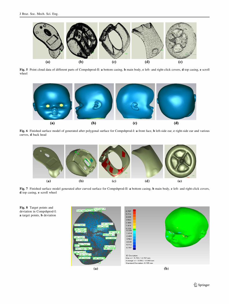
Fig. 5 Point cloud data of different parts of Compshprod-II: a bottom casing, b main body, c left- and right-click covers, d top casing, e scroll
wheel
Fig. 6 Finished surface model of generated after polygonal surface for Compshprod-I: a front face, b left-side ear, c right-side ear and various
curves, d back head
Fig. 7 Finished surface model generated after curved surface for Compshprod-II: a bottom casing, b main body, c left- and right-click covers,
d top casing, e scroll wheel
Fig. 8 Target points and
deviation in Compshprod-I:
a target points, b deviation
J Braz. Soc. Mech. Sci. Eng.
123

portion but remaining part is almost noise free. The noise
needs to be carefully reduced to ensure the accuracy of
complex features. Compshprod-I is without hair (no beard,
no eye brow and bald headed). This was selected to avoid
unnecessary shape. Moreover, due to restriction in layer
thickness hair are difficult to reverse engineer.
Figures 6 and 7 show the surface models obtained from
polygonal surface and curved surface for Compshprod-I
and Compshprod-II, respectively. As a result of close
visual comparison of actual Compshprod-I and Compsh-
prod-II with the respective finished surface model it can be
said that complex features have been reproduced with a
reasonable degree of accuracy. Moreover, no feature is lost
during this process.
The curved surface model was generated for Compsh-
prod-II to compensate for size variation which might result
due to noise reduction. The sub-parts of Compshprod-II are
thin with curved features and some have holes as well. This
led to the formation of saw-toothed shape at edges and
holes due to the presence of noise. To remove saw tooth
shapes, the edges might be smoothened via creating
boundary around the part which in turn would result in
reduction of size of sub-parts. Variation in sizes of sub-
parts could be problematic during the final assembly and
fitting. The problem was overcome by generating patches
on polygonal model and then curves were created (Fig. 7).
These curves can be easily modified as per scale to ensure
proper assembly of sub-parts. In the case of holes, all holes
were filled and created again as per required size.
Figure 8a, b shows the set target points on different
features for alignment and statistical analysis, respectively,
for Compshprod-I. Similar procedure was used for the
statistical analysis of the surface model of Compshprod-II.
Deviations of the surface models from the original 3D
scanned data are presented in Table 4. It is clear from
Fig. 8b that the regions that deviated more are those where
corrections have been made to remove dents and other
imperfections in the model. All other regions deviated
within a range of ±0.339 mm. Such an analysis is helpful
in making early decisions for the acceptance or rejection of
the surface model and for taking necessary actions to
improve the product quality.
Figures 9, 10 and 11 show reverse-engineered models of
Compshprod-I developed through Sys-I and Sys-II and
Compshprod-II developed through Sys-II, respectively. For
the same layer thickness (0.1 mm), Compshprod-I devel-
oped through Sys-I by employing Mat-I has rough surface
as compared to Compshprod-I developed through Sys-II by
employing Mat-II. The reasons behind better surface finish
generated through Sys-II lie with the material as well as
nature of the process itself. There is a room for further
improvements in surface finish and strength as the layer
thickness can be further reduced to the lowest value of
0.089 mm as per specifications of Sys-II. The roughness
values taken with surface texture meter (Surtronic S 25,
Taylor Hobson Precision) for both models of Compshprod-
Table 4 Deviations between surface models and original 3D data
S. No. Product Max.
deviation
(mm)
Average
deviation
(mm)
Standard
deviation
(mm)
1 Compshprod-I ?5.703/
-6.787
?0.056/
-0.040
0.195
2 Compshprod-II
Main body ?1.685/
-3.089
?0.009/
-0.009
0.020
Top casing ?0.040/
-3.024
?0.006/
-0.003
0.006
Bottom casing ?0.162/
-2.605
?0.014/
-0.006
0.020
Left-click cover and
right-click cover
?0.182/
-0.072
?0.018/
-0.006
0.030
Scroll wheel ?2.680/
-1.785
?0.072/
-0.020
0.153
Fig. 9 Different views of RP model of Compshprod-I with Sys-I: a front face, b left-side ear, c right-side ear and various curves, d right ear
enlarged
J Braz. Soc. Mech. Sci. Eng.
123
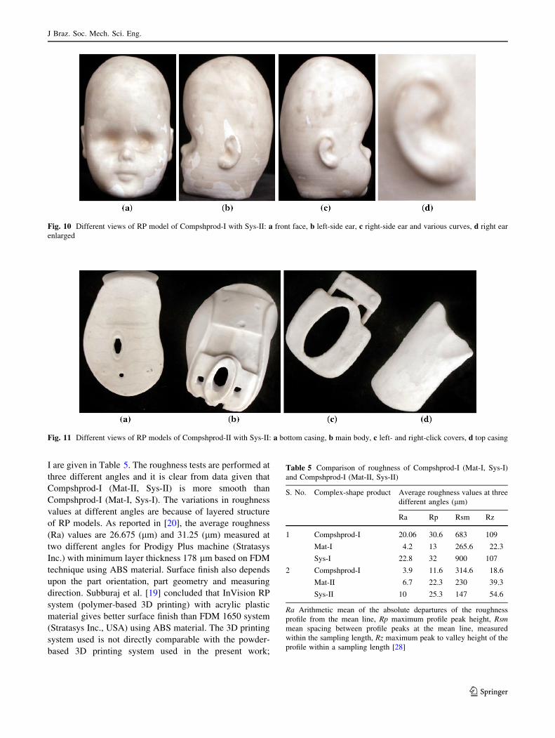
I are given in Table 5. The roughness tests are performed at
three different angles and it is clear from data given that
Compshprod-I (Mat-II, Sys-II) is more smooth than
Compshprod-I (Mat-I, Sys-I). The variations in roughness
values at different angles are because of layered structure
of RP models. As reported in [20], the average roughness
(Ra) values are 26.675 (lm) and 31.25 (lm) measured at
two different angles for Prodigy Plus machine (Stratasys
Inc.) with minimum layer thickness 178 lm based on FDM
technique using ABS material. Surface finish also depends
upon the part orientation, part geometry and measuring
direction. Subburaj et al. [19] concluded that InVision RP
system (polymer-based 3D printing) with acrylic plastic
material gives better surface finish than FDM 1650 system
(Stratasys Inc., USA) using ABS material. The 3D printing
system used is not directly comparable with the powder-
based 3D printing system used in the present work;
Fig. 10 Different views of RP model of Compshprod-I with Sys-II: a front face, b left-side ear, c right-side ear and various curves, d right ear
enlarged
Fig. 11 Different views of RP models of Compshprod-II with Sys-II: a bottom casing, b main body, c left- and right-click covers, d top casing
Table 5 Comparison of roughness of Compshprod-I (Mat-I, Sys-I)
and Compshprod-I (Mat-II, Sys-II)
S. No. Complex-shape product Average roughness values at three
different angles (lm)
Ra Rp Rsm Rz
1 Compshprod-I 20.06 30.6 683 109
Mat-I 4.2 13 265.6 22.3
Sys-I 22.8 32 900 107
2 Compshprod-I 3.9 11.6 314.6 18.6
Mat-II 6.7 22.3 230 39.3
Sys-II 10 25.3 147 54.6
Ra Arithmetic mean of the absolute departures of the roughness
profile from the mean line, Rp maximum profile peak height, Rsm
mean spacing between profile peaks at the mean line, measured
within the sampling length, Rz maximum peak to valley height of the
profile within a sampling length [28]
J Braz. Soc. Mech. Sci. Eng.
123

however, both techniques are very close. Thus, it can be
said that FDM process gives higher roughness values than
3D printing system.
Feature details in regions of rapid changes in contours and
increased number of features per unit surface area (ear, nose,
lips and eyes) have not been captured properly in RP model
of Compshprod-I manufactured on Sys-I by employing Mat-
I. Some features even cannot be distinguished as shown in
upper part of right ear (Fig. 9c, d) where curved features are
not visible due to excessive accumulation of fused material.
Experimental results reported in [19, 20] using FDM and
ABS material show an increase in error with a reduction in
size of the features. Moreover, Noy [20] concluded that the
FDM process is not adequate for generating slots below
0.4 mm and ribs below 0.4 mm. Similar trend is apparent in
the present work. The RP model of Compshprod-I developed
through Sys-II by employing Mat-II with binder closely
resembles the actual object with clear feature details.
Moreover, Compshprod-I produced by Sys-I by employing
Mat-I (based on fused deposition method) showed lack of
continuity (disjointed) in layers whenever there is a
D1
D2
D3
D4
D5
D6
Fig. 12 Various dimensions of Compshprod-I
Table 6 Comparison of RP
models with original physical
model (Compshprod-I)
Dimensions
(Fig. 8)
Original physical model
(mm)
Sys-I Sys-II
RP model
(mm)
Difference
(%)
RP model
(mm)
Difference
(%)
D1 62.68 60.71 3.14 60.68 3.19
D2 10.12 9.54 5.73 9.86 2.57
D3 76.83 74.94 2.45 75.00 2.38
D4 60.11 62.21 3.49 62.30 3.64
D5 17.94 17.07 4.85 17.49 2.51
D6 13.56 12.86 5.16 13.24 2.36
Fig. 13 Assembly of Compshprod-II developed with Sys-II
J Braz. Soc. Mech. Sci. Eng.
123

considerable change in circumference during upward
movement along vertical direction. No such shortcoming was
observed in Compshprod-I RP model developed through
Sys-II by employing Mat-II with binder. Due to this reason,
RP model of Compshprod-II was developed through Sys-II
by employing Mat-II only. It can be attributed to slicing
limitation in FDM process.
Various dimensions (Fig. 12) were measured on original
physical model and then comparison was made with RP
models (Table 6). It is clear from Table 6 that dimensional
accuracy of RP model with Sys-II and Mat-II is within
acceptable limits.
It is clear from Fig. 13 that sub-parts can be easily
assembled which indicates dimensional accuracy of the
produced sub-parts. The knurling/graduation on the scroll
wheel to facilitate grip and avoid slippage has been produced
with minimum layer thickness (0.089 mm). Thus, it can be
said that powder-based layer-by-layer manufacturing method
is more appropriate for reverse engineering of complex-
shape products of small size with low weight. Features can be
modified during surface model generation to customize the
products. In this way, development cycle of customized
complex-shape products can be shortened. Finally, virtual
model can be developed and after analysis RP system can be
used to make a mold. However, this is limited to material and
one such example has been reported by [19].
It is evident from Table 7 that layer-by-layer manufac-
turing through fused deposition method (FDM) took longer
time (20� h) as compared to ceramic powder-based layer-
by-layer manufacturing (5� h) to produce same complex-
shape product. On the other hand, variable cost (material and
electricity) as well as fixed cost (initial cost of machine) are
higher for ceramic powder-based layer-by-layer manufac-
turing to produce customized complex-shape products.
4 Conclusions
The present study was carried out to explore the suitable
method and material for the development of complex-shape
products with the dual objectives of minimization of product
development cycle time and cost. The speed of fabrication
processes, reproduction of intricate features, incorporation of
customized features, surface quality of produced models,
material and method selection and process shortcoming/
limitations have been discussed in detail. Following con-
clusions can be drawn from the present study.
1. Time-to-market plays a crucial role in the successful
marketing of customized products. This can be
successfully reduced by minimizing the product
development time.
2. Setting of target points accompanied by statistical
analysis of generated surface models is helpful in
improving product quality by ensuring dimensional
accuracy within acceptable limits.
3. RE of complex shapes can be accomplished if suitable
material and method are selected. Ceramic-based layer-
by-layer manufacturing is appropriate method to produce
customized complex-shape products with small size. FDM
cannot capture complex feature details like rapid changes
in contours, increased number of features/area, etc.
4. The results of roughness tests show that ceramic-based
layer-by-layer manufacturing has better surface finish
as compared to fused deposition method.
5. The parameter settings play a significant role in the
reproduction of intricate features, rotating parts, parts
to be assembled and surface finish during RE of
complex-shape products.
6. Fixed and variable costs are higher for ceramic-based
layer-by-layer printing as compared to FDM layer-by-
layer manufacturing; however, time consumed is
considerably low in case of earlier system.
Acknowledgments The authors acknowledge the support of
Department of Industrial and Manufacturing Engineering, UET La-
hore in carrying out the experimental work.
References
1. Hosni YA, Harrysson OLA (2002) Design and manufacturing of
customized implants. IERC 2002, Orlando, Florida, USA, May 19–21
Table 7 RP models and economic analysis
S. No. Complex-shape product Material Method Materialconsumed (g)
Time (h)
1 Compshprod-I Acrylonitrile butadiene styrene (ABS)
(Mat-I)
Layer-by-layer manufacturing through FDM
Sys-I
140 g 20�
2 Compshprod-I (i) Plaster Powder (ZP-131)
(ii) Binder (Zb-60)
(iii) Infiltrant (Z-Bond-101)
(Mat-II)
Layer-by-layer manufacturing through powder-based printing 3DP
Sys-II
(i) 230 gm
(ii) 65.7 ml
(iii) 5 g
5�
3 Compshprod-II (i) 122 g
(ii) 43 ml
(iii) 6 gm
4�
J Braz. Soc. Mech. Sci. Eng.
123

2. Zhang Y, Liu H (2009) Application of rapid prototyping tech-
nology in die making of diesel engine. Tsinghua Sci Technol
21/38, 14(S1):127–131
3. Al Mardini M, Ercoli C, Graser GN (2005) A technique to pro-
duce a mirror-image wax pattern of an ear using rapid proto-
typing technology. J Prosthet Dent 94(2):195–198
4. Lohfeld JS, McHugh P, Serban D, Boyle D, O’ Donnell G,
Peckitt N (2007) Engineering assisted surgery: a route for digital
design and manufacturing of customized maxillofacial implants.
J Mater Process Tech 183:333–338
5. Pham DT, Gault RS (1998) A comparison of rapid prototyping
technologies. Int J Mach Tool Manuf 38:1257–1287
6. Yan Y, Li S, Zhang R, Lin F, Wu R, Lu Q, Xiong Z, Wang X
(2009) Rapid prototyping and manufacturing technology: prin-
ciple, representative technics, applications, and development
trends. Tsinghua Sci Technol 01/38, 14(S1):1–12
7. Olszewski R (2013) Three-dimensional rapid prototyping models
in cranio-maxillofacial surgery: systematic review and new
clinical applications. In: Proceedings of the Belgian Royal
Academies of Medicine
8. Chua CK, Hong KH, Ho SL (1999) Rapid tooling technology. Part
1. A comparative study. Int J Adv Manuf Technol 15:604–608
9. Horvath I, Yang D-Y (2002) Rapid technologies: solutions for
today and tomorrow. Comput Aided Des 34:679–682
10. Ibrahim D, Broilo TL, Heitz C, De Oliveira MG, De Oliveira
HW, Nobre SM, Dos Santos Filho JH, Silva DN (2009)
Dimensional error of selective laser sintering, three-dimensional
printing and PolyJet models in the reproduction of mandibular
anatomy. J Craniomaxillofac Surg 37:167–173
11. Safira LC, Bastos LC, Beal VE, de Azevedo RA, Francischone
CE, Sarmento VA (2013) Accuracy of rapid prototyping bio-
models plotted by three dimensional printing technique: ex vivo
study. Adv Comput Tomogr 2:41–45
12. Bill JS, Reuther JF, Dittmann W, Kubler N, Meir JL, Pistner H,
Wittenberg G (1995) Stereolithography in oral and maxillofacial
operation planning. Int J Oral Maxillofac Surg 24:98–103
13. D’Urso PS, Atkinson RL, Lanigan MW, Earwaker WJ, Bruce IJ,
Holmes A, Barker TM, Effeney DJ, Thompson RG (1998) Ste-
reolithographic (SL) biomodelling in craniofacial surgery. Br J
Plast Surg 51:522–530
14. D’Urso PS, Earwaker WJ, Barker TM, Redmond MJ, Thompson
RG, Effeney DJ, Tomlinson FH (2000) Custom cranioplasty
using stereolithography and acrylic. Br J Plast Surg 53:200–204
15. Silva DN, Gerhardt de Oliveira M, Meurer E, Meurer MI, Lopes
da Silva JV, Santa-Barbara A (2008) Dimensional error in
selective laser sintering and 3D-printing of models for cranio-
maxillary anatomy reconstruction. J Craniomaxillofac Surg
36:443–449
16. Choi JY, Choi JH, Kim NK, Kim Y, Lee JK, Kim MK, Lee JH,
Kim MJ (2002) Analysis of errors in medical rapid prototyping
models. Int J Oral Maxillofac Surg 31(1):23–32
17. Nizam A, Gopal RN, Naing L, Hakim AB, Samsudin AR (2006)
Dimensional accuracy of the skull models produced by rapid
prototyping technology using stereolithography apparatus. Arch
Orofac Sci 1:60–66
18. Cohen A, Laviv A, Berman P, Nashef R, Abu-Tair J (2009)
Mandibular reconstruction using stereolithographic 3-dimen-
sional printing modeling technology. Oral Surg Oral Med Oral
Pathol Oral Radiol Endodontol 108(5):661–666
19. Subburaj K, Nair C (2007) Rapid development of auricular
prosthesis using CAD and rapid prototyping technologies. J Oral
Maxillofac Surg Med 36:938–943
20. Noy L (2005) An investigation of the performance of low cost
rapid prototyping machines. M.Sc. Thesis, DE Montfort Uni-
versity. Available on. http://www.Google.com
21. Childs THC, Juster NP (1994) Linear and geometric accuracies
from layer manufacturing. CIRP Ann 43(1):163–166
22. Jacobs PF (1992) Rapid prototyping and manufacturing: funda-
mentals of stereolithography. Soc Manuf Eng 1992:32–52
23. Ma’aram A, Sharif S, Zakaria K, Mohamed J (2003) Quality
assessment of hollow prototypes model in fused deposition
modelling. Master thesis, Universiti Teknologi Malaysia
24. Hayat N, Ashraf R, Javed O, Zulfiqar Z (2009) Reverse engi-
neering of doll’s head using 3D laser scanning, printing and rapid
prototyping. Under graduate project Department of Industrial and
Manufacturing Engineering, UET, Lahore
25. Hayat N, Adrees A, Sipra SN, Umer Farooq M (2009) Reverse
engineering of ergonomically designed mouse and design of its
Virtual mold. Under graduate project Department of Industrial
and Manufacturing Engineering, UET, Lahore
26. Hayat N et al (2011) Rapid product development: a case study of
ergonomically designed mouse. Pak J Sci 63(2):32–48
27. Rapid prototyping lab, UET, Lahore. www.uet.edu.pk
28. Taylor-Hobson Surtronic S 25 operational manual
J Braz. Soc. Mech. Sci. Eng.
123