rapid loading system - engineering projects specs... · rapid loading system volume ... schedule of...
TRANSCRIPT
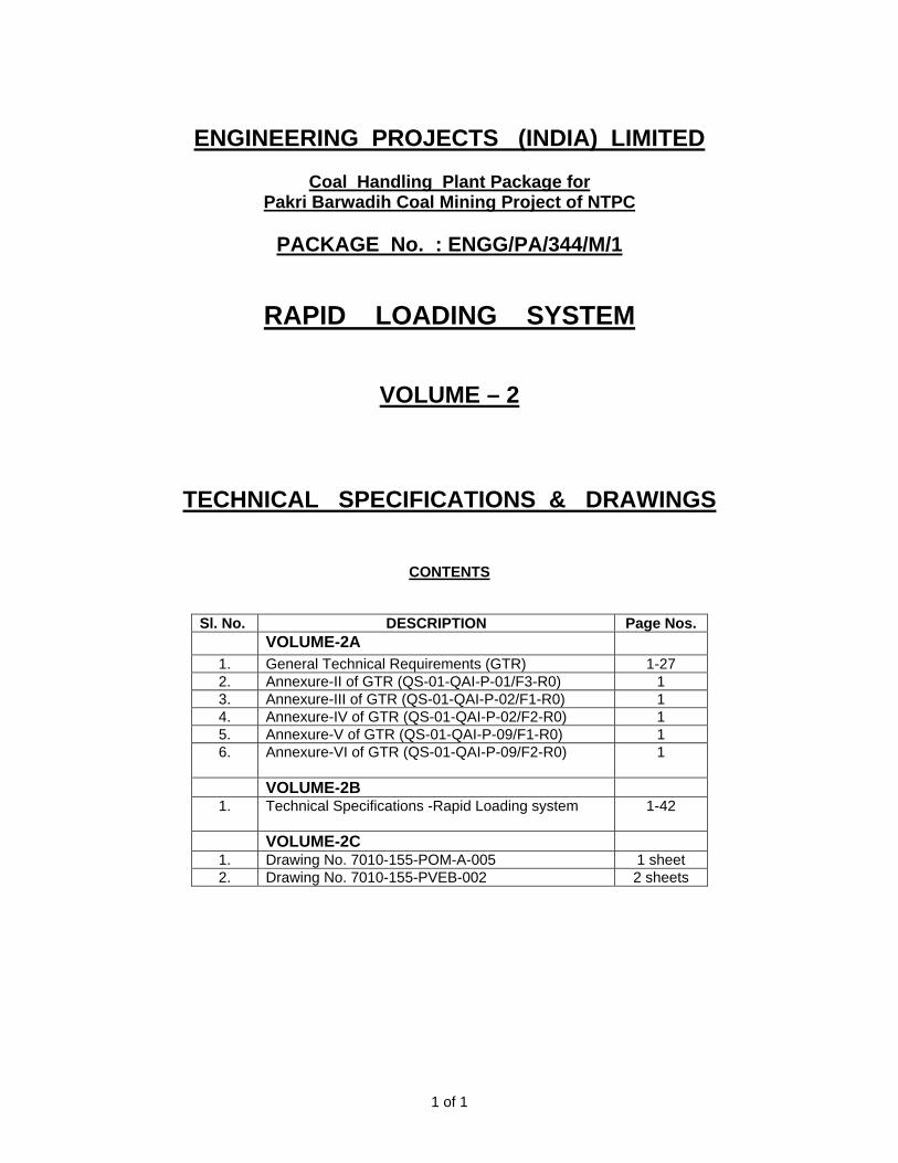
ENGINEERING PROJECTS (INDIA) LIMITED
Coal Handling Plant Package for
Pakri Barwadih Coal Mining Project of NTPC
PACKAGE No. : ENGG/PA/344/M/1
RAPID LOADING SYSTEM
VOLUME – 2
TECHNICAL SPECIFICATIONS & DRAWINGS
CONTENTS
Sl. No. DESCRIPTION Page Nos. VOLUME-2A
1. General Technical Requirements (GTR) 1-27 2. Annexure-II of GTR (QS-01-QAI-P-01/F3-R0) 1 3. Annexure-III of GTR (QS-01-QAI-P-02/F1-R0) 1 4. Annexure-IV of GTR (QS-01-QAI-P-02/F2-R0) 1 5. Annexure-V of GTR (QS-01-QAI-P-09/F1-R0) 1 6. Annexure-VI of GTR (QS-01-QAI-P-09/F2-R0)
1
VOLUME-2B 1. Technical Specifications -Rapid Loading system
1-42
VOLUME-2C 1. Drawing No. 7010-155-POM-A-005 1 sheet 2. Drawing No. 7010-155-PVEB-002 2 sheets
1 of 1

GENERAL TECHNICAL REQUIREMENTS
1.00.00 INTRODUCTION
This part covers technical requirements, which will form an integral part of the specifications. The following provisions shall supplement all the detailed technical requirements brought out in the Technical Specifications and the Technical Data Sheets.
2.00.00 BASE OFFER
Vendor’s proposal shall be based upon the use of equipment and material complying fully with the requirements specified herein. It is recognized that the Vendor may have standardized on the use of certain components, materials, processes or procedures different than those specified herein.
3.00.00 COMPLETENESS OF FACILITIES
3.01.00 Vendor may note that this is a contract inclusive of the scope as indicated elsewhere in the specification. Each of the plant/equipment shall be engineered and designed in accordance with the specification requirement. All engineering and associated services are required to ensure that a completely engineered plant/equipment is provided.
3.02.00 All equipments furnished by the Vendor shall be complete in every respect, with all mountings, fittings, fixtures and standard accessories normally provided with such equipment and/or those needed for erection, completion and safe operation & maintenance of the equipment and for the safety of the operating personnel, as required by applicable codes, though they may not have been specifically detailed in the respective specifications, unless included in the list of exclusions. All similar standard components/ parts of similar standard equipment provided, shall be interchangeable with one another.
4.00.00 CODES & STANDARDS
4.01.00 In addition to the codes and standards specifically mentioned in the relevant technical specifications for the equipment / plant / system, all equipment parts, systems and works covered under this specification shall comply with all currently applicable statutory regulations and safety codes of the Republic of India as well as of the locality where they will be installed, including the following:
(a.) Bureau of Indian Standards (BIS)
(b.) Indian electricity act
(c.) Indian electricity rules
(d.) Indian Explosives Act
(e.) Indian Factories Act and State Factories Act
(f.) Indian Boiler Regulations (IBR)
(g.) Regulations of the Central Pollution Control Board, India
(h.) Regulations of the Ministry of Environment & Forest (MoEF), Government of India
(i.) Pollution Control Regulations of Department of Environment, Government of India
(j.) State Pollution Control Board.
(k.) Rules for Electrical installation by Tariff Advisory Committee (TAC).
(l.) Any other statutory codes / standards / regulations, as may be applicable.
1 of 27

4.02.00 The codes, and/or standards referred to in these specifications shall govern, in all the cases wherever such references are made for design of various equipments/system etc. Latest edition shall be followed by the Vendor for all the codes and /or Standards. In case of a conflict between such codes and/or standards and the specifications, the latter shall govern such codes and/or standard referred to shall mean the latest revision, amendments/changes adopted and published by the relevant agencies. In case of any further conflict in this matter the same shall be referred to the Employer whose decision shall be final and binding.
4.03.00 Other internationally acceptable standards which ensure equal or higher performance than those specified shall also be accepted subject to the EPI / Employer's approval, for which the Vendor shall furnish, adequate information to justify that these standards are equivalent or superior to the standards referred. In all such cases the Vendor shall furnish specifically the variations and deviations from the standards mentioned else where in the specification together with the complete word to word translation of the standard that is normally not published in English.
4.04.00 In case of any change in codes, standards & regulations between the date of bid opening and the date when vendors proceed with fabrication, the EPI/Employer shall have the option to incorporate the changed requirements or to retain the original standard. It shall be the responsibility of the Vendor to bring to the notice of the Employer such changes and advise EPI/Employer of the resulting effect.
5.00.00 EQUIPMENT FUNCTIONAL GUARANTEE
5.01.00 The functional guarantees of the equipment under the scope of the Contract is given elsewhere in the technical specification. These guarantees shall supplement the general functional guarantee provisions covered under General Conditions of Contract.
5.02.00 Liquidated damages for shortfall in meeting functional guarantee(s) during the performance and guarantee tests shall be assessed and recovered from the Vendor as specified elsewhere in this specification.
6.00.00 DESIGN OF FACILITIES/MAINTENANCE & AVAILABILITY CONSIDERATIONS
6.01.00 Design of Facilities
All the design procedures, systems and components proposed shall have already been adequately developed and shall have demonstrated good reliability under similar conditions elsewhere.
Vendor shall be responsible for the selection and design of appropriate equipments to provide the best co-ordinated performance of the entire system. The basic requirements are detailed out in various clauses of the Technical Specifications. The design of various components, assemblies and subassemblies shall be done so that it facilitates easy field assembly and dismantling. All the rotating components shall be so selected that the natural frequency of the complete unit is not critical or close to the operating range of the unit.
6.02.00 Maintenance and Availability Considerations
Equipment/facilities offered shall be designed for high availability, low maintenance and ease of maintenance. Vendor shall specifically state the design features incorporated to achieve high degree of reliability/ availability and ease of maintenance.
Lifting devices i.e. hoists and chain pulley jacks, etc. shall be specified separately by the Vendor for handling of any equipment or any of its part having weight in excess of 500 Kgs during erection and maintenance activities.
Lifting devices like lifting tackles, slings, etc. to be connected to hook of the hoist / crane shall be provided by the Vendor for lifting the equipment and accessories covered under the specification during erection & commissioning.
2 of 27

All the valves and other equipments shall be provided with operating platforms, ladders, lifting lugs etc as required by Employer and such appurtenances if required during /after commissioning of the plant shall be provided by the Vendor at plant within the contract price.
7.00.00 DOCUMENTS, DATA DRAWINGS AND ENGINEERING CO-ORDINATION PROCEDURE.
7.01.00 Vendor may note that this is a contract inclusive of the scope as indicated elsewhere in the specification. Each of the plant and equipment shall be fully integrated, engineered and designed to perform in accordance with the technical specification. All engineering and technical services required ensuring a completely engineered plant shall be provided in respect of mechanical, electrical, control & instrumentation, civil & structural works as per the scope.
Vendor shall furnish engineering data/drawings and manuals in accordance with the schedule of information as specified in Technical Specification and data sheets.
7.02.00 The number of copies/prints/floppy discs/CD-ROMs/manuals to be furnished for various types of documents is given in Annexure-I of this Section. In addition to numbers indicated, 2 sets of each of drawings & 1 set CD/Floppies shall also be furnished.
7.03.00 The documentation that shall be provided by the Vendor is indicated in the various sections of specification. This documentation shall in general include (whichever applicable for the package) but not be limited to the following as mentioned below.
7.03.01 Detailed Engineering Documents i) General layout ii) Layouts, general arrangements, elevations and cross-sections drawings for all
the equipment and facilities of the plant. iii) Flow diagrams, Process & Instrumentation Diagrams. iv) Piping isometric /composite layout and fabrication drawings. v) Piping engineering diagrams, pipe and fittings schedules, valve schedules,
hanger and support schedules, insulation schedules. vi) Technical data sheets for all bought out and manufactured items. Vendor shall
use the technical specifications as a base for placement of orders on their sub-vendors.
vii) Detailed design calculations for components, system, piping etc., wherever applicable.
viii) Transient, hydraulic and thermal stress analysis of piping and system wherever applicable & input and output data alongwith stress analysis isometrics showing nodes.
ix) Characteristic Curves/ Performance Correction Curves applicable for various equipments.
x) Comprehensive list of all terminal points which interface with Employer's facilities. giving details of location, terminal pressure, temperature, fluid handled & end connection details, forces, moments etc.
xi) Power supply single line diagram, block logics, control schematics, electrical schematics, etc.
xii) Protection system diagrams and settings. xiii) Cables schedules and interconnection diagrams. xiv) Cable routing plan. xv) Instrument schedule, measuring point list, I/O list, Interconnection & wiring
diagram, functional write-ups, installation drawings for field mounted instruments, logic diagrams, control schematics, wiring and tubing diagrams of panels and enclosures etc. Drawings for open loop and close loop controls (both hardware and software). Motor list and valve schedule including type of actuator etc.
xvi) Alarm and annunciation/ Sequence of Event (SOE) list and alarms & trip set points.
3 of 27

xvii) Sequence and protection interlock schemes. xviii) Type test reports. xix) Control system configuration diagrams and card circuit diagrams and
maintenance details. xx) Detailed software manuals & source software listing. xxi) Detailed flow chart for digital control system. xii) Mimic diagram layout. xxiii) Civil drawings for architectural works, foundations and super-structural works,
civil calculation sheets including structural analysis and design along with output results.
xxiv) Underground facilities, levelling ,sanitary, landscaping drawings. xxv) Geo-technical investigation and site survey reports (as applicable). xxvi) Model study reports wherever applicable. xxvii) Functional & guarantee test procedures and test reports. xxviii) Documentation in respect of Quality Assurance System as listed out elsewhere in
this specification.
Vendor's while submitting the above documents/ drawings for approval/ reference as the case may be, shall mark on each copy of submission the reference letter along with the date vide which the submissions are made.
7.03.02 Instruction Manuals
Vendor shall submit to EPI, draft Instruction Manuals for all the equipments and as well as for the complete system covered under the Contract within the time agreed upon between EPI and the Vendor. The Instruction manuals shall contain full details required for erection, commissioning, operation and maintenance of each equipment. The manual shall be specifically compiled for this project.
The Instruction Manuals of plant / equipment / system shall comprise of the following :
i) Erection Manuals
The erection manuals shall be submitted atleast three (3) months prior to the commencement of erection activities of particular equipment/system. The erection manual should contain the following as a minimum. a) Erection strategy. b) Sequence of erection. c) Erection instructions. d) Critical checks and permissible deviation/tolerances. e) List of tool, tackles, heavy equipments like cranes, dozers, etc. f) Bill of Materials g) Procedure for erection. h) General safety procedures to followed during erection/installation. i) Procedure for initial checking after erection. j) Procedure for testing and acceptance norms. k) Procedure / Check list for pre-commissioning activities. l) Procedure / Check list for commissioning of the system. m) Safety precautions to be followed in erection all equipments and electrical supply
distribution during erection.
ii) Operation & Maintenance (O & M) Manuals
a) The manual shall be a two rim PVC bound stiff sided binder able to withstand constant usage or where a thicker type is required it shall have locking steel pins, the size of the manual shall not be larger than international size A3. The cover shall be printed with the Project Name, Services covered and Volume / Book number Each section of the manual shall be divided by a stiff divider of the same
4 of 27

size as the holder. The dividers shall clearly state the section number and title. All written instructions within the manual not provided by the manufacturers shall be typewritten with a margin on the left hand side.
b) The arrangement and contents of O & M manuals shall be as follows : 1) Chapter 1 - Plant Description : To contain the following sections specific to the
equipment/system supplied (a) Description of operating principle of equipment / system with schematic drawing /
layouts. (b) Functional description of associated accessories / controls. Control interlock
protection writeup. (c) Integrated operation of the equipment alongwith the intended system. (The is to
be given by the supplier of the Main equipment by taking into account the operating instruction given by the associated suppliers).
(d) Exploded view of the main equipment, associated accessories and auxiliaries with description. Schematic drawing of the equipment alongwith its accessories and auxiliaries.
(e) Design data against which the plant performance will be compared. (f) Master list of equipments, Technical specification of the equipment/ system and
approved data sheets. (g) Identification system adopted for the various components, (it will be of a simple
process linked tagging system). (h) Master list of drawings (as built drawing - Drawings to be enclosed in a separate
volume). 2) Chapter 2.0 - Plant Operation : To contain the following sections specific to the
equipment supplied (a) Protection logics provided for the equipment alongwith brief philosophy behind
the logic, Drawings etc. (b) Limiting values of all protection settings. (c) Various settings of annunciation/interlocks provided. (d) Startup and shut down procedure for equipment alongwith the associated
systems in step mode. (e) Do's and Don'ts related to operation of the equipment. (f) Safety precautions to be take during normal operation. Emergency instruction on
total power failure condition/lubrication failure/any other conditions. (g) Parameters to be monitored with normal value and limiting values. (h) Equipment isolating procedures. (i) Trouble shooting with causes and remedial measures. (j) Routine testing procedure to ascertain healthiness of the safety devices
alongwith schedule of testing. (k) Routine Operational Checks, Recommended Logs and Records (l) Change over schedule if more than one auxiliary for the same purpose is given. (m) Preservation procedure on long shut down. (n) System/plant commissioning procedure. 3) Chapter 3.0 - Plant Maintenance: To contain the following sections specific to the
equipment supplied. (a) Exploded view of each of the equipments. Drawings alongwith bill of materials
including name, code no. & population. (b) Exploded view of the spare parts and critical components with dimensional
drawings (In case of Electronic cards, the circuit diagram to be given) and spare parts catalogue for each equipment.
5 of 27

(c) List of Special T/ P required for Overhauling /Trouble shooting including special testing equipment required for calibration etc.
(d) Stepwise dismantling and assembly procedure clearly specifying the tools to be used, checks to be made, records to be maintained etc. Clearance to be maintained etc.
(e) Preventive Maintenance schedules linked with running hours/calendar period alongwith checks to be carried out.
(f) Overhauling schedules linked with running hours/calendar period alonwith checks to be done.
(g) Long term maintenance schedules (h) Consumables list alongwith the estimated quantity required during normal
running and during maintenance like Preventive Maintenance and Overhauling. (i) List of lubricants with their Indian equivalent, Lubrication Schedule including
charts showing lubrication checking, testing and replacement procedure to be carried daily, weekly, monthly & at longer intervals to ensure trouble free operation and quantity required for complete replacement..
(j) Tolerance for fitment of various components. (k) Details of sub vendors with their part no. in case of bought out items. (l) List of spare parts with their Part No, total population, life expediency & their
interchangeability with already supplied spares. (m) List of mandatory and recommended spare list along with manufacturing
drawings, material specification & quality plan for fast moving consumable spares.
(n) Lead time required for ordering of spares from the equipment supplier, instructions for storage and preservation of spares.
(o) General information on the equipment such as modification carried out in the equipment from its inception, equipment population in the country / foreign country and list of utilities where similar equipments have been supplied.
7.03.03 After finalization and approval of the Employer, the O & M Manuals shall be submitted as indicated in Annexure-I. The Contract shall not be considered to be completed for purposes of taking over until the final Instructions manuals (both erection and O & M manuals have been supplied to EPI / Employer.
If after the commissioning and initial operation of the plant, the instruction manuals (Erection and /or O &M manuals) require modifications/additions/ changes, the same shall be incorporated and the updated final instruction manuals shall be submitted by the Vendor to the EPI/Employer for records and number of copies shall be as mentioned in Annexure-1.
7.03.04 Project Completion Report.
Vendor shall submit a Project Completion Report at the time of handing over the plant/equipment.
7.04.00 Engineering Data / Drawings
7.04.01 All data/ information furnished by Vendor in the form of drawings/ documents/catalogues or in any other form for NTPC’s information/ interface and or review and approval are referred by the general term “drawings”.
7.04.02 All documents submitted by the Vendor for EPI/Employer's review shall be in electronic form (soft copies) along with the desired number of hard copies as per Annexure-I . The soft copies to be supplied shall be either in CDs, Floppies or through direct transfer via E-mail, etc. depending upon the nature/volume/size of the document. The drawings submitted for approval shall be in the Image form / Autocad drawing format / pdf format readable through Acrobat Reader as mutually agreed to between Vendor and EPI before award of Contract. All documents/text /calculations etc
6 of 27

information shall be in MS Office application such as MS – WORD or MS-Excel as the case may be.
7.04.03 All drawings submitted by the Vendor including those submitted at the time of bid shall be in sufficient detail indicating the type, size, arrangement, weight of each component for packing and shipment, the external connection, fixing arrangement required, the dimensions required for installation and interconnections with other equipments and materials, clearance and spaces required between various portions of equipment and any other information specifically requested in the drawing schedules.
7.04.04 Each drawing submitted by the Vendor (including those of sub-vendors of Vendor) shall bear a title block at the right hand bottom corner with clear mention of the name of EPI & Employer, the system designation, the specifications title, the specification number, the name of the Project, drawing number and revisions. If standard catalogue pages are submitted the applicable items shall be indicated therein. All titles, noting, markings and writings on the drawing shall be in English. All the dimensions should be in metric units. A sample of ‘TITLE’ Block shall be furnished to the successful vendor.
7.04.05 The drawings submitted by the Vendor (or their sub-vendors) shall bear Employer’s drawing number wherever available in addition to Vendor’s (their sub-vendor’s) own drawing number. Employer’s drawing numbering system shall be made available to the successful Vendor so as to enable him to assign Employer’s drawing numbers to the drawings to be submitted by him during the course of execution of the Contract.
7.04.06 Vendor shall also furnish a “Master Drawing List” which shall be a comprehensive list of all drawings/ documents/ calculations envisaged to be furnished by him during the detailed engineering to EPI along with the schedule of submission of each drawing/document. Such list should clearly indicate the purpose of submission of these drawings i.e. “FOR APPROVAL” or “FOR INFORMATION ONLY”.
7.04.07 The review of these drawings by EPI/Employer will cover only general conformance of the data to the specifications and documents, interfaces with the equipment provided under specifications, external connections, and of the dimensions which might affect plant layout. This review by EPI/Employer may not indicate a thorough review of all dimensions, quantities and details of the equipment, materials, any devices or items indicated or the accuracy of the information submitted. This review and/or approval by the Employer shall not be relieve the Vendor of any of his responsibilities and liabilities under this Contract.
7.04.08 After the approval of the drawings, further work by the Vendor shall be in strict accordance with these approved drawings and no deviation shall be permitted without the written approval of EPI/Employer.
7.04.09 All manufacturing, fabrication and execution of work in connection with the equipment / system, prior to the approval of the drawings, shall be at the Vendor’s risk.
7.04.10 Vendor is expected not to make any changes in the design of the equipment /system, once they are approved by the Employer. However, if some changes are necessitated in the design of the equipment/system at a later date, vendor may do so, but such changes shall promptly be brought to the notice of the Employer indicating the reasons for the change and get the revised drawing approved again in strict conformance to the provisions of the Technical Specification.
7.04.11 Drawings shall include all installations and detailed piping layout drawings. Layout drawings for all piping of 65 mm and larger diameter shall be submitted for review/ approval of Employer prior to erection. Small diameter pipes shall however be routed as per site conditions in consultation with site authority / representative of Employer based on requirements of such piping indicated in approved / finalized Flow Scheme / Process & Instrumentation Diagrams and/or the requirements cropping up for draining
7 of 27

& venting of larger diameter piping or otherwise after their erection as per actual physical condition for the entire scope of work of this package.
7.04.12 Assessing & anticipating the requirement and supply of all piping and equipment hall be done by the contractor well in advance so as not to hinder the progress of piping & equipment erection, subsequent system charging and its effective draining venting arrangement as per site suitability.
7.04.13 Final copies of the approved drawings shall be submitted in vector form on CD-ROM long with the requisite number of hard copies as per Annexure-I.
7.04.14 As Built Drawings
After final acceptance of individual equipment / system by the Employer at the plant/site, the Vendor will update all original drawings and documents for the equipment / system to “as built” conditions.
7.04.15 All engineering data submitted by the Vendor after final process including review and approval by the Employer/Project Manager shall form part of the contract documents and the entire works covered under these specification shall be performed in strict conformity with technical specifications unless otherwise expressly requested by the Employer / Project Manager in writing.
7.05.00 Engineering Information Submission Schedule Prior to the award of Contract, a Detailed Engineering Information Submission
Schedule shall be tied up with EPI. For this, Vender shall furnish a detailed list of engineering information alongwith the proposed submission schedule. This list would be a comprehensive one including all engineering data / drawings / information for all bought out items and manufactured items. The information shall be categorised into the following parts. (a) Information that shall be submitted to EPI for the approval of the Employer before proceeding further, and (b) Information that would be submitted to EPI for Employer’s information only.
The schedule should allow adequate time for proper review and incorporation of
changes/ modifications, if any, to meet the contract without affecting the equipment delivery schedule and overall project schedule. The early submission of drawings and data is as important as the manufacture and delivery of equipment and hardware and this shall be duly considered while determining the overall performance and progress.
7.06.00 Engineering Co-ordination Procedure 7.06.01 The following coordinators will be identified by respective organizations at time of
award of contract :
NTPC Engineering Coordinator (NTPC FC): Name : Designation : Address : a) Postal : b) Telegraphic / e-Mail : c) FAX : TELEPHONE : EPI’s Engineering Coordinator: Name : Designation : Address : a) Postal : b) Telegraphic / e-Mail : c) FAX : TELEPHONE :
8 of 27

Vendor’s Engineering Coordinator (VENDOR EC): Name : Designation : Address : a) Postal : b) Telegraphic / e-Mail :
c) FAX : TELEPHONE 7.06.02 All engineering correspondence shall be in the name of above coordinators on behalf of
the respective organizations.
7.06.03 Vendor’s Drawing Submission and Approval Procedure :
a) All data/information furnished by vendor in the form of drawings/documents/ catalogues or in any other form for EPI/NTPC’s information/ interface and or review and approval are referred by the general term “drawings”.
b) The ‘Master drawings list’ indicating titles, Drawing Number, Date of submission and approval etc. shall be finalised mutually between Vendor, EPI and Employer before the award of contract. This list shall be updated if required at suitable interval during detailed engineering.
c) All drawings (including those of sub-vendor’s) shall bear at the right hand bottom corner the ‘title plate’ with all relevant information duly filled in. Vendor shall furnish this format to his sub-vendor along with his purchase order for sub-vendor’s compliance.
d) Employer, EPI and Vendor shall follow their own numbering systems for the drawings. However, EPI shall intimate to the Vendor, NTPC drawing number on receipt of the first submission of each drawing. Vendor, thereafter, shall indicate NTPC’s drawing number in subsequent Submission, in the space provided for this purpose in title plate, in addition to his own drawing number.
e) Vendor shall make a visit to site to see the existing facilities and understand the
layout completely and collect all necessary data / drawings at site which are needed as an input to the engineering. Vendor shall do the complete engineering including interfacing and integration of all his equipment, systems & facilities within his scope of work as well as interface engineering & integration of systems, facilities, equipment & works under Employer’s scope and submit all necessary drawings/ documents for the same.
f) Drawings must be checked by the Vendor in terms of its completeness, data adequacy and relevance with respect to Engineering schedule prior to submission to the Employer. In case drawings are found to be submitted without proper endorsement for checking by the Vendor, the same shall not be reviewed and returned to the Vendor for re-submission.
g) Vendor shall submit to EPI, adequate prints of drawing / data / document for Employer’s review and approval. The drawings submitted by the vendor shall be reviewed by EPI/NTPC and their comments shall be forwarded within four (4) weeks of receipt of drawings. Upon review of each drawing, depending on the correctness and completeness of the drawing, the same will be categorized and approval accorded in one of the following categories :
CATEGORY- I : Approved
CATEGORY- II : Approved, subject to incorporation of comments/ modification as noted. Resubmit revised drawing incorporating the comments.
9 of 27

CATEGORY –III : Not approved. Resubmit revised drawings for approval after incorporating comments/ modification as noted.
CATEGORY –IV : For information and records.
h) Vendor shall resubmit the drawings approved under Category II, III & IV within two (2) weeks or earlier of receipt of comments on the drawings, incorporating all comments. Every revision of the drawing shall bear a revision index wherein such revisions shall be highlighted in the form of description or marked up in the drawing identifying the same with relevant revision Number enclosed in a triangle (eg. 1, 2, 3 etc). Vendor shall not make any changes in the portions of the drawing other than those commented. If changes are required to be made in the portions already approved, the Vendor shall resubmit the drawing identifying the changes for EPI/Employer’s review and approval. Drawings resubmitted shall show clearly the portions where the same are revised marking the relevant revision numbers and EPI/Employer shall review only such revised portion of documents.
i) In case, the Vendor does not agree with any specific comment, he shall furnish the explanation for the same to EPI/NTPC for consideration. In all such cases the Vendor shall necessarily enclose explanations along with the revised drawing (taking care of balance comments) to avoid any delay and/or duplication in review work.
j) It is responsibility of the Vendor to get all the drawings approved in the Category I & IV (as the case may be) and complete engineering activities within the agreed schedule. Any delay arising out of submission and modification of drawings shall not alter the contract completion schedule.
k) If Vendor fails to resubmit the drawings as per the schedule, construction work at site will not be held up and work will be carried out on the basis of comments furnished on previous issues of the drawing.
l) These comments will be taken care by the Vendor while submitting the revised drawing.
m) Vendor shall use a single transmittal for drawings submission. This shall include transmittal numbers and date, number of copies being sent, names of the agencies to whom copies being sent, drawing number and titles, remarks or special notes if any etc.
7.06.04 Engineering Progress Reporting /Exception Report
Vendor shall prepare every calendar month, at his own cost progress reports describing the engineering activities in the reporting month, in a from and size acceptable to the Engineering coordinator. The progress report shall be in three sections.
In the first, all major engineering activities that took place during the reporting month
shall be clearly described, indicating major delays the agency responsible and any corrective actions taken.
The second section shall show an exception report showing the list of
drawings/engineering information which remains unapproved for more than four (4) weeks after the date of submission.
The third shall comprise drawings. Submission and approval status, listed separately
(i.e). for drawings submitted during the reporting month and drawings commented and approved during the reporting month.
10 of 27

Lastly the fourth section shall contain the ordering status of bought out items. The formats for ‘Drawing submission and approval Status’ and ‘Bought out’ items ordering status shall be furnished to the Vendor for his compliance, at the time of award of contract.
7.06.05 Technical Co-Ordination Meeting
a) Vendor shall be called upon to organise and attend monthly Design/ Technical Co-ordination Meetings(TCMs) with EPI/Employer/Employer’s representatives and other Vendors of EPI/ Employer during the period of contract. Vendor shall attend such meetings at his own cost at NEW DELHI / NOIDA or at mutually agreed venue as and when required and fully co-operate with such persons and agencies involved during the discussions.
b) Vendor should note that Time is the essence of the contract. In order to expedite the early completion of engineering activities, Vendor shall submit all drawings as per the agreed Engineering Information Submission Schedule. The drawings submitted by the Vendor will be reviewed by EPI/ Employer as far as practicable within four (4) weeks from the date of receipt of the drawing .The comments of EPI/Employer shall then be discussed across the table during the above Technical Co-ordination Meeting (s) wherein best efforts shall be made by both sides to ensure the approval of the drawing.
c) Vendor shall ensure availability of the concerned experts / consultants/ personnel/sub-vendor who are empowered to take necessary decisions during these meetings. Vendor shall be equipped with necessary tools and facilities so that the drawings/documents can be resubmitted after incorporating necessary changes and approved during the meeting itself.
d) Should any drawing remain unapproved for more than six (6) weeks after it’s first submission, this shall be brought out in the monthly Engineering Progress and Exception Report with reasons thereof.
e) Any delays arising out of failure by the Vendor to incorporate Employer’s comments and resubmit the same during the TCM shall be considered as a default and in no case shall entitle the Vendor to alter the Contract completion date.
7.07.00 Design Improvements
The Employer/ EPI may propose changes in the specification of the equipment or quality thereof and if the parties agree upon any such changes the specification shall be modified accordingly.
If any such agreed upon change is such that it affects the price and schedule of completion, the parties shall agree in writing as to the extent of any changing the price and/or schedule of completion before the Vendor proceeds with the change. Following such agreement, the provision thereof, shall be deemed to have been amended accordingly.
7.08.00 Equipment Bases
A cast iron or welded steel base plate shall be provided for all rotating equipment which is to be installed on a concrete base, unless otherwise specifically agreed to by EPI/ Employer. Each base plate which support the unit and its drive assembly, shall be of a neat design with pads for anchoring the units, shall have a raised lip all around, and shall have threaded drain connections.
11 of 27

8.00.00 PROTECTIVE GUARDS
Suitable guards shall be provided for protection of personnel on all exposed rotating and/or moving machine parts. All such guards shall be designed for easy installation and removal for maintenance purpose.
9.00.00 LUBRICANTS, SERVO FLUIDS AND CHEMICALS
9.01.00 Vendor’s scope includes all the first fill and one year’s topping, requirements of consumables such as oils, lubricants including grease, servo fluids, gases and essential chemicals etc. Consumption of all these consumables during the initial operation and final filling after the initial operation shall also be included in the scope of the Vendor. Vendor shall also supply a quantity not less than 10% of the full charge of each variety of lubricants, servo fluids, gases, chemicals etc. used which is expected to be utilised during the first year of operation. This additional quantity shall be supplied in separate Containers.
9.02.00 As far as possible lubricants marketed by the Indian Oil Corporation shall be used. The variety of lubricants shall be kept to a minimum possible. Detailed specifications for the lubricating oil, grease, gases, servo fluids, control fluids, chemicals etc. required for the complete plant covered herein shall be furnished. On completion of erection, a complete list of bearings/ equipment giving their location and identification marks shall be furnished to the Employer alongwith lubrication requirements.
9.03.00 Equipment shall be lubricated by systems designed for continuous operation. Lubricant level indicators shall be furnished and marked to indicate proper levels under both standstill and operating conditions.
10.00.00 MATERIAL OF CONSTRUCTION
All materials used for the construction of the equipment shall be new and shall be in accordance with the requirements of this specification. Materials utilised for various components shall be those which have established themselves for use in such applications.
11.00.00 RATING PLATES, NAME PLATES & LABELS
a) Each main and auxiliary item of plant including instruments shall have permanently attached to it in a conspicuous position, a rating plate of non-corrosive material upon which shall be engraved manufacturer’s name, equipment, type or serial number together with details of the ratings, service conditions under which the item of plant in question has been designed to operate, and such diagram plates as may be required by the Employer.
b) Each item of plant shall be provided with nameplate or label designating the service of the particular equipment. The inscriptions shall be approved by EPI/Employer or as detailed in appropriate section of the technical specifications.
c) Such nameplates or labels shall be of white nonhygroscopic material with engraved black lettering or alternately, in the case of indoor circuit breakers, starters, etc. of transparent plastic material with suitably coloured lettering engraved on the back. The name plates shall be suitably fixed on both front and rear sides.
d) Items of plant such as valves, which are subject to handling, shall be provided with an engraved chromium plated nameplate or label with engraving filled with enamel. The name plates for valves shall be marked in accordance with MSS standard SP- 25 and ANSI B 16.34 as a minimum.
e) Hanger/ support numbers shall be marked on all pipe supports, anchors, hangers, snubbers and restraint assemblies. Each constant and variable spring support shall
12 of 27
also have stamped upon it the designed hot and cold load which it is intended to support. Suitable scale shall also be provided to indicate load on support/hanger.
f) Valves, steam traps and strainers shall be identified by Employer’s tag number of a metal tap permanently attached to non pressure parts such as the yoke by a stainless steel wire. The direction of flow shall also be marked on the body.
g) Safety and relief valves shall be provided with Manufacturer’s identification, Nominal inlet and outlet sizes in mm, Set pressure in Kg/cm2 (abs), Blow down and accumulation as percentage of set pressure and Certified capacity in Kg of saturated steam per hour or in case of liquid certified capacity in litres of water per minute.
h) All such plates, instruction plates, etc. shall be bilingual with Hindi inscription first, followed by English. Alternatively, two separate plates one with Hindi and the other with English inscriptions may be provided.
i) All segregated phases of conductors or bus ducts, indoor or outdoor, shall be provided with coloured phase plates to clearly identify the phase of the system
12.00.00 TOOLS AND TACKLES
Vendor shall supply with the equipment one complete set of all special tools and tackles and other instruments required for the erection, assembly, disassembly and proper maintenance of the plant and equipment and systems (including software). These special tools will also include special material handling equipment, jigs and fixtures for maintenance and calibration / readjustment, checking and measurement aids etc. A list of such tools and tackles shall be submitted by the Vendor alongwith the offer.
The price of each tool / tackle shall be deemed to have been included in the total bid price. These tools and tackles shall be separately packed and sent to site. Vendor shall also ensure that these tools and tackles are not used by him during erection, commissioning and initial operation. For this period Vendor should bring his own tools and tackles. All the tools and tackles shall be of reputed make acceptable to the Employer.
13.00.00 WELDING
If the manufacturer has special requirements relating to the welding procedures for welds at the terminals of the equipments to be per formed by others the requirements shall be submitted to EPI/ Employer in advance of commencement of erection work.
14.00.00 COLOUR CODE FOR ALL EQUIPMENTS/ PIPINGS/ PIPE SERVICES
All equipment/ piping/ pipe services are to be painted by the Vendor in accordance with Employer’s standard colour coding scheme, which will be furnished to the Vendor during detailed engineering stage.
15.00.00 PROTECTION AND PRESERVATIVE SHOP COATING PROTECTION
15.01.00 All coated surfaces shall be protected against abrasion, impact, discoloration and any other damages. All exposed threaded portions shall be suitably protected with either metallic or a nonmetallic protection device. All ends of all valves and pipings and conduit equipment connections shall be properly sealed with suitable devices to protect them from damage. The parts which are likely to get rusted, due to exposure to weather, should also be properly treated and protected in a suitable manner. All primers/paints/coatings shall take into account the hot humid, corrosive & alkaline, subsoil or overground environment as the case may be.
13 of 27

15.02.00 Preservative Shop Coating
15.02.01 All exposed metallic surfaces subject to corrosion shall be protected by shop application of suitable coatings. All surfaces which will not be easily accessible after the shop assembly, shall be treated beforehand and protected for the life of the equipment. All surfaces shall be thoroughly cleaned of all mill scales, oxides and other coatings and prepared in the shop. The surfaces that are to be finish-painted after installation or require corrosion protection until installation, shall be shop painted with atleast two coats of primer unless otherwise mentioned in the technical specification.
15.02.02 Transformers and other electrical equipments if included shall be shop finished with one or more coats of primer and two coats of high grade resistance enamel. The finished colors shall be as per manufacturer’s standards, to be selected and specified by the Employer at a later date.
15.02.03 Shop primer for all steel surfaces which will be exposed to operating temperature below 95 degrees Celsius shall be selected by the Vendor after obtaining specific approval of the Employer regarding the quality of primer proposed to be applied. Special high temperature primer shall be used on surfaces exposed to temperature higher than 95 degrees Celsius and such primer shall also be subject to the approval of the Employer.
15.02.04 All other steel surfaces which are not to be painted shall be coated with suitable rust preventive compound subject to the approval of the Employer.
15.02.05 All piping shall be cleaned after shop assembly by shot blasting or other means approved by the Employer. Lube oil piping or carbon steel shall be pickled.
15.02.06 Painting for Civil structures shall be done as per relevant part of technical specification
16.00.00 QUALITY ASSURANCE PROGRAMME
16.01.00 Vendor shall adopt suitable quality assurance programme to ensure that the equipment and services under the scope of contract whether manufactured or performed within the Vendor’s works or at his sub-Vendor’s premises or at the Employer’s site or at any other place of work are in accordance with the specifications. Such programmes shall be outlined by the Vendor and shall be finally accepted by the Employer/authorised representative after discussions before the award of the contract. The QA programme shall be generally in line with IS/ISO- 9001.A quality assurance programme of the Vendor shall generally cover the following:
a) His organisation structure for the management and implementation of the proposed quality assurance programme
b) Quality System Manual
c) Design Control System
d) Documentation and Data Control System
e) Qualification data for Vendor’s key personnel.
f) The procedure for purchase of materials, parts, components and selection of sub-Vendor’s services including vendor analysis, source inspection, incoming raw-material inspection, verification of materials purchased etc.
g) System for shop manufacturing and site erection controls including process, fabrication and assembly.
h) Control of non-conforming items and system for corrective actions and resolution of deviations.
i) Inspection and test procedure both for manufacture and field activities.
14 of 27

j) Control of calibration and testing of measuring testing equipment.
k) System for Quality Audits.
l) System for identification and appraisal of inspection status.
m) System for authorising release of manufactured product to the Employer.
n) System for handling, storage and delivery.
o) System for maintenance of records, and
p) Quality plans for manufacturing and field activities detailing out the specific quality control procedure adopted for controlling the quality characteristics relevant to each item of equipment/component.
16.02.00 General Conditions - Quality Assurance
16.02.01 All materials, components and equipment covered under this specification shall be procured, manufactured, erected, commissioned and tested at all the stages, as per a comprehensive Quality Assurance Programme. An indicative programme of inspection/tests to be carried out by the Vendor for some of the major items is given in the respective technical specification. This is, however, not intended to form a comprehensive programme as it is the Vendor’s responsibility to draw up and implement such programme duly approved by the Employer. The detailed Quality Plans for manufacturing and field activities shall be drawn up by the Vendor and will be submitted to Employer for approval. Schedule of finalisation of such quality plans will be finalised before award. Monthly progress reports on Manufacturing Quality Plan (MQP)/ Field Quality Plan (FQP) submission/approval shall be furnished on enclosed format No. QS-01-QAI-P-02/F1.
16.02.02 MQP will detail out for all the components and equipment, various tests/inspection, to be carried out as per the requirements of this specification and standards mentioned therein and quality practices and procedures followed by Vendor’s/ Sub- Vendor’s/ sub-supplier's Quality Control Organisation, the relevant reference documents and standards, acceptance norms, inspection documents raised etc., during all stages of materials procurement, manufacture, assembly and final testing/performance testing. The Quality Plan shall be submitted on electronic media e.g. floppy or E-mail in addition to hard copy, for review and approval. After approval the same shall be submitted in compiled form on CD-ROM.
16.02.03 FQPs will detail out for all the equipment, the quality practices and procedures etc. to be followed by the Vendor’s "Site Quality Control Organisation", during various stages of site activities starting from receipt of materials/equipment at site.
16.02.04 Vendor shall also furnish copies of the reference documents/plant standards/acceptance norms/tests and inspection procedure etc., as referred in Quality Plans along with Quality Plans. These Quality Plans and reference documents/standards etc. will be subject to Employer’s approval without which manufacturer shall not proceed. These approved documents shall form a part of the contract. In these approved Quality Plans, Employer shall identify customer hold points (CHP), i.e. test/checks which shall be carried out in presence of the Employer’s Project Manager or his authorised representative and beyond which the work will not proceed without consent of Employer in writing. All deviations to this specification, approved quality plans and applicable standards must be documented and referred to Employer along with technical justification for approval and dispositioning.
16.02.05 No material shall be despatched from the manufacturer’s works before the same is accepted, subsequent to predespatch final inspection including verification of records of all previous tests/inspections by Employer’s Project Manager/Authorised representative
15 of 27

and duly authorised for despatch by issuance of Material Despatch Clearance Certificate (MDCC).
16.02.06 All material used for equipment manufacture including casting and forging etc. shall be of tested quality as per relevant codes/standards. Details of results of the tests conducted to determine the mechanical properties; chemical analysis and details of heat treatment procedure recommended and actually followed shall be recorded on certificates and time temperature chart. Tests shall be carried out as per applicable material standards and/or agreed details.
16.02.07 Vendor shall submit to the Employer Field Welding Schedule for field welding activities in the enclosed format No.: QS-01-QAI-P-02/F3. The field welding schedule shall be submitted to the Employer along with all supporting documents, like welding procedures, heat treatment procedures, NDT procedures etc. at least ninety days before schedule start of erection work at site.
16.02.08 All welding and brazing shall be carried out as per procedure drawn and qualified in accordance with requirements of ASME Section IX/BS-4870 or other International equivalent standard acceptable to the Employer.
16.02.09 All welding/brazing procedures shall be submitted to the Employer or its authorized representative for approval prior to carrying out the welding/brazing.
16.02.10 All brazers, welders and welding operators employed on any part of the contract either in Vendor’s/sub- Vendor ‘s works or at site or elsewhere shall be qualified as per ASME Section-IX or BS-4871 or other equivalent International Standards acceptable to the Employer.
16.02.11 Welding procedure qualification & Welder qualification test results shall be furnished to the Employer for approval. However, where required by the Employer, tests shall be conducted in presence of Employer/authorised representative.
16.02.12 For all pressure parts and high pressure piping welding, the latest applicable requirements of the IBR (Indian Boiler Regulations) shall also be essentially complied with. Similarly, any other statutory requirements for the equipment/systems shall also be complied with. On all back-gauged welds MPI/LPI shall be carried before seal welding.
16.02.13 Unless otherwise proven and specifically agreed with the Employer, welding of dissimilar materials and high alloy materials shall be carried out at shop only.
16.02.14 No welding shall be carried out on cast iron components for repair.
16.02.15 All the heat treatment results shall be recorded on time temperature charts and verified with recommended regimes.
16.02.16 All non-destructive examination shall be performed in accordance with written procedures as per International Standards, The NDT operator shall be qualified as per SNT-TC-IA (of the American Society of non-destructive examination). NDT shall be recorded in a report, which includes details of methods and equipment used, result/evaluation, job data and identification of personnel employed and details of correlation of the test report with the job.
All plates of thickness above 40mm & all bar stock/Forging above 40mm dia shall be ultrasonically tested. For pressure parts, plate of thickness equal to or above 25mm shall be ultrasonically tested.
16.02.17 Vendor shall list out all major items/ equipment/ components to be manufactured in house as well as procured from sub- Vendor (BOI). All the sub Vendor proposed by the Vendor for procurement of major bought out items including castings, forging, semi-finished and finished components/ equipment etc., list of which shall be drawn up by the Vendor and finalised with the Employer, shall be subject to Employer's approval.
16 of 27

The Vendor’s proposal shall include vendor’s facilities established at the respective works, the process capability, process stabilization, QC systems followed, experience list, etc. along with his own technical evaluation for identified sub-Vendor enclosed and shall be submitted to the Employer for approval within the period agreed at the time of pre-awards discussion and identified in "DR" category prior to any procurement. Monthly progress reports on sub-Vendor detail submission / approval shall be furnished on enclosed on format no. QS-01-QAI-P-02/F2. Such vendor approval shall not relieve the Vendor from any obligation, duty or responsibility under the contract.
16.02.18 For components/equipment procured by the Vendor for the purpose of the contract, after obtaining the written approval of the Employer, the Vendor’s purchase specifications and inquiries shall call for quality plans to be submitted by the suppliers. The quality plans called for from the sub-Vendor shall set out, during the various stages of manufacture and installation, the quality practices and procedures followed by the vendor’s quality control organisation, the relevant reference documents/standards used, acceptance level, inspection of documentation raised, etc. Such quality plans of the successful vendors shall be finalised with the Employer and such approved Quality Plans shall form a part of the purchase order/contract between the Vendor and sub-Vendor. With in three weeks of the release of the purchase orders /contracts for such bought out items /components, a copy of the same without price details but together with the detailed purchase specifications, quality plans and delivery conditions shall be furnished to the Employer on the monthly basis by the Vendor along with a report of the Purchase Order placed so far for the contract.
16.02.19 Employer reserves the right to carry out quality audit and quality surveillance of the systems and procedures of the Vendor’s or their sub-Vendor’s quality management and control activities. Vendor shall provide all necessary assistance to enable the Employer carry out such audit and surveillance.
16.02.20 Vendor shall carry out an inspection and testing programme during manufacture in his work and that of his sub-Vendor’s and at site to ensure the mechanical accuracy of components, compliance with drawings, conformance to functional and performance requirements, identity and acceptability of all materials parts and equipment. Vendor shall carry out all tests/inspection required to establish that the items/equipment conform to requirements of the specification and the relevant codes/standards specified in the specification, in addition to carrying out tests as per the approved quality plan.
16.02.21 Quality audit/surveillance/approval of the results of the tests and inspection will not, however, prejudice the right of the Employer to reject the equipment if it does not comply with the specification when erected or does not give complete satisfaction in service and the above shall in no way limit the liabilities and responsibilities of the Vendor in ensuring complete conformance of the materials/equipment supplied to relevant specification, standard, data sheets, drawings, etc.
16.02.22 For all spares and replacement items, the quality requirements as agreed for the main equipment supply shall be applicable.
16.02.23 Repair/rectification procedures to be adopted to make the job acceptable shall be subject to the approval of the Employer/ authorised representative.
16.02.24 Burn in and Elevated Temperature Test Requirement for Electronics Solid State Equipment All solid state electronic systems/equipment shall be tested as a complete system/equipment with all devices connected for a minimum of 168 hours (7 Days) continuously under energized conditions prior to shipment from manufacturing works, as per the following cycle.
a) Elevated Temperature Test Cycle
During the elevated temperature test which shall be for 48 hours of the total 168 hours of testing, the ambient temperature shall be maintained at 50 deg.C. The equipment
17 of 27
shall be interconnected with devices which will cause it to repeatedly perform all operations it is expected to perform in actual service with load on various components being equal to those which will be experienced in actual service.
During the elevated temperature test the cubicle doors shall be closed (or shall be in the position same as they are supposed to be in the field) and inside temperature in the zone of highest heat dissipating components/modules shall be monitored. The temperature rise inside the cubicle should not exceed 10 deg.C above the ambient temp. at 50 deg.C.
b) Burn in Test Cycle
The 48 hours elevated temperature test shall be followed by 120 hours of burn in test as above except that the temperature shall be reduced to the ambient temperature prevalent at that time.
During the above tests, the process I/O and other load on the system shall be simulated by simulated inputs and in the case of control systems, the process which is to be controlled shall also be simulated. Testing of individual components or modules shall not be acceptable.
In case Vendor /sub-Vendor is having any alternate established procedure of eliminating infant mortile components, the detail procedures followed by the Vendor/ sub- Vendor along with the statistical figures to validate the alternate procedure to be forwarded.
Vendor/Sub- Vendor shall carry out routine test on 100% item at Vendor /sub-Vendor’s works. The quantum of check/test for routine & acceptance test by employer shall be generally as per criteria/sampling plan defined in referred standards. Wherever standards have not been mentioned quantum of check/test for routine / acceptance test shall be as agreed during detailed engineering stage.
16.03.00 QA DOCUMENTATION PACKAGE
16.03.01 Vendor shall be required to submit the QA Documentation in two hard copies and two CD ROMs, as identified in respective quality plan with tick (#) mark.
16.03.02 Each QA Documentation shall have a project specific Cover Sheet bearing name &identification number of equipment and including an index of its contents with page control on each document.
The QA Documentation file shall be progressively completed by the Supplier’s subsupplier to allow regular reviews by all parties during the manufacturing.
The final quality document will be compiled and issued at the final assembly place of equipment before dispatch. However CD-Rom may be issued not later than three weeks.
16.03.03 Typical contents of QA Documentation is as below:-
a) Quality Plan
b) Material mill test reports on components as specified by the specification and approved Quality Plans.
c) Manufacturer / works test reports/results for testing required as per applicable codes and standard referred in the specification and approved Quality Plans.
d) Non-destructive examination results /reports including radiography interpretation reports. Sketches/drawings used for indicating the method of traceability of the radiographs to the location on the equipment.
e) Heat Treatment Certificate/Record (Time- temperature Chart).
18 of 27

f) All the accepted Non-conformance Reports (Major/Minor)/ deviation, including complete technical details/repair procedure).
g) CHP / Inspection reports duly signed by the Inspector of the Employer and Vendor for the agreed Customer Hold Points.
h) Certificate of Conformance (COC) wherever applicable.
i) MDCC
16.03.04 Similarly, Vendor shall be required to submit two sets (two hard copies and two CD ROMs), containing QA Documentation pertaining to field activities as per Approved Field Quality Plans and other agreed manuals/ procedures, prior to commissioning of individual system.
16.03.05 Before Dispatch / commissioning of any equipment, the Supplier shall make sure that the corresponding quality document or in the case of protracted phased deliveries, the applicable section of the quality document file is completed. The supplier will then notify the Inspector regarding the readiness of the quality document (or applicable section) for review.
If the result of the review carried out by the Inspector is satisfactory, the Inspector shall stamp the quality document (or applicable section) for release.
If the quality document is unsatisfactory, the Supplier shall endeavor to correct the incompleteness, thus allowing to finalize the quality document (or applicable section) by time compatible with the requirements as per contract documents. When it is done, the quality document (or applicable section) is stamped by the Inspector.
If a decision is made Dispatch, whereas all outstanding actions cannot be readily cleared for the release of the quality document by that time. The supplier shall immediately, upon shipment of the equipment, send a copy of the quality document Review Status signed by the Supplier Representative to the Inspector and notify of the committed date for the completion of all outstanding actions & submission. The Inspector shall stamp the quality document for applicable section when it is effectively completed. The submission of QA documentation package shall not be later than 3 weeks after the Dispatch of equipment.
16.03.06 Transmission of QA Documentation
On release of QA Documentation by Inspector, one set of quality document shall be forwarded to Corporate Quality Assurance Department and other set to respective Project Site of Employer.
For the particular case of phased deliveries, the complete quality document to the Employer shall be issued not later than 3 weeks after the date of the last delivery of equipment.
16.04.00 Project Manager’s Supervision 16.04.01 To eliminate delays and avoid disputes and litigation, it is agreed between the parties to
the Contract that all matters and questions shall be referred to the Project Manager and without prejudice to the provisions of ‘Arbitration’ clause in Section GCC of Vol.I, Vendor shall proceed to comply with the Project Manager's decision.
16.04.02 The work shall be performed under the supervision of the Project Manager. The scope
of the duties of the Project Manager pursuant to the Contract, will include but not be limited to the following: a) Interpretation of all the terms and conditions of these documents and
specifications: b) Review and interpretation of all Vendor’s drawing, engineering data, etc:
19 of 27

c) Witness or his authorised representative to witness tests and trials either at the manufacturer’s works or at site, or at any place where work is performed under the contract :
d) Inspect, accept or reject any equipment, material and work under the contract : e) Issue certificate of acceptance and/or progressive payment and final payment
certificates f) Review and suggest modifications and improvement in completion schedules from
time to time, and
g) Supervise Quality Assurance Programme implementation at all stages of the works.
16.05.00 Inspection, Testing And Inspection Certificates
16.05.01 The word ‘Inspector’ shall mean the Project Manager and/or his authorized representative and/or an outside inspection agency acting on behalf of the Employer to inspect and examine the materials and workmanship of the works during its manufacture or erection.
16.05.02 The Project Manager or his duly authorised representative and/or an outside inspection agency acting on behalf of the Employer shall have access at all reasonable times to inspect and examine the materials and workmanship of the works during its manufacture or erection and if part of the works is being manufactured or assembled on other premises or works, the Vendor shall obtain for the Project Manager and for his duly authorised representative permission to inspect as if the works were manufactured or assembled on the Vendor’s own premises or works.
16.05.03 Vendor shall give the Project Manager/Inspector fifteen (15) days written notice of any material being ready for testing. Such tests shall be to the Vendor’s account except for the expenses of the Inspector’s. The Project Manager/Inspector, unless the witnessing of the tests is virtually waived and confirmed in writing, will attend such tests within fifteen (15) days of the date on which the equipment is noticed as being ready for test/inspection failing which Vendor may proceed with test which shall be deemed to have been made in the inspector’s presence and he shall forthwith forward to the inspector duly certified copies of test reports in two (2) copies.
16.05.04 The Project Manager or Inspector shall within fifteen (15) days from the date of inspection as defined herein give notice in writing to the Vendor, or any objection to any drawings and all or any equipment and workmanship which is in his opinion not in accordance with the contract. Vendor shall give due consideration to such objections and shall either make modifications that may be necessary to meet the said objections or shall inform in writing to the Project Manager/Inspector giving reasons therein, that no modifications are necessary to comply with the contract.
16.05.05 When the factory tests have been completed at the Vendor’s or sub-Vendor’s works, the Project Manager /Inspector shall issue a certificate to this effect fifteen (15) days after completion of tests but if the tests are not witnessed by the Project Manager /Inspectors, the certificate shall be issued within fifteen (15) days of the receipt of the Vendor’s test certificate by the Project Manager /Inspector. Project Manager /Inspector to issue such a certificate shall not prevent the Vendor from proceeding with the works. The completion of these tests or the issue of the certificates shall not bind the Employer to accept the equipment should it, on further tests after erection be found not to comply with the contract.
16.05.06 In all cases where the contract provides for tests whether at the premises or works of the Vendor or any sub-Vendor, the Vendor, except where otherwise specified shall provide free of charge such items as labour, material, electricity, fuel, water, stores, apparatus and instruments as may be reasonably demanded by the Project Manager /Inspector or his authorised representatives to carry out effectively such tests on the
20 of 27

equipment in accordance with the Vendor and shall give facilities to the Project Manager/Inspector or to his authorised representative to accomplish testing.
16.05.07 The inspection by Project Manager / Inspector and issue of Inspection Certificate thereon shall in no way limit the liabilities and responsibilities of the Vendor in respect of the agreed Quality Assurance Programme forming a part of the contract.
16.05.08 To facilitate advance planning of inspection in addition to giving inspection notice as specified above the Vendor shall furnish quarterly inspection programme indicating schedule dates of inspection at Customer Hold Point and final inspection stages. Updated quarterly inspection plans will be made for each three consecutive months and shall be furnished before beginning of each calendar month.
16.05.09 All inspection, measuring and test equipment used by Vendor shall be calibrated periodically depending on its use and criticality of the test/measurement to be done. Vendor shall maintain all the relevant records of periodic calibration and instrument identification, and shall produce the same for inspection by NTPC. Wherever asked specifically, Vendor shall re-calibrate the measuring/test equipment in the presence of Project Manager / Inspector.
16.06.00 Associated Document For Quality Assurance Programme:
a) List of items requiring quality plan and sub supplier approval. Format No.:QS- 01-QAI-P-01/F3-R0 (Annexure-II).
b) Status of items requiring Quality Plan and sub supplier approval. Format No.: QS-01-QAI-P-02/F1-R0 (Annexure-III).
c) Field Welding Schedule Format No.: QS-01-QAI-P-02/F2-R0 (Annexure-IV).
d) Manufacturing Quality Plan Format No.: QS-01-QAI-P-09/F1-R0 (Annexure-V).
e) Field Quality Plan Format No.: QS-01-QAI-P-09/F2-R0 (Annexure-VI).
17.00.00 PRE-COMMISSIONING AND COMMISSIONING FACILITIES
a) As soon as the facilities or part thereof has been completed operationally and structurally and before start-up, each item of the equipment and systems forming part of facilities shall be thoroughly cleaned and then inspected jointly by the Employer and the Vendor for correctness of and completeness of facility or part thereof and acceptability for initial pre-commissioning tests, commissioning and start-up at Site. The list of pre-commissioning tests to be performed shall be as mutually agreed and included in the Vendor’s quality assurance programme as well as those included elsewhere in the Technical Specifications.
b) Vendor’s pre-commissioning/ commissioning/start-up engineers, specially identified as far as possible, shall be responsible for carrying out all the pre-commissioning tests at Site. On completion of inspection, checking and after the pre-commissioning tests are satisfactorily over, the commissioning of the complete facilities shall be commenced during which period the complete facilities, equipments shall be operated integral with sub-systems and supporting equipment as a complete plant.
c) All piping system shall be flushed, steam blown, air blown as required and cleanliness demonstrated using acceptable industry standards. Procedures to accomplish this work shall be submitted for approval to the Employer six months prior to the respective implementations. The Employer will approve final verification of cleanliness.
d) The time consumed in the inspection and checking of the units shall be considered as a part of the erection and installation period.
21 of 27

e) The check outs during the pre - commissioning period should be programmed to follow the construction completion schedule. Each equipment/system, as it is completed in construction and turned over to Employer's commissioning (start-up) Engineer(s), should be checked out and cleaned. The checking and inspection of individual systems should then follow a prescribed commissioning documentation [SLs (Standard Check List) / TS (Testing Schedule) / CS (Commissioning Schedule)] approved by the Employer.
f) Vendor during initial operation and performance testing shall conduct vibration testing to determine the ‘base line’ of performance of all plant rotating equipment. These tests shall be conducted when the equipment is running at the base load, peak load as well as lowest sustained operating condition as far as practicable.
g) Vendor shall furnish the commissioning organization chart for review & acceptance of employer at least eighteen months prior to the schedule date of synchronization of 1st unit. The chart should contain :
i) Biodata including experience of the Commissioning Engineers.
ii) Role and responsibilities of the Commissioning Organisation members.
iii) Expected duration of posting of the above Commissioning Engineers at site.
18.00.00 Initial Operation
(a) On completion of all pre-commissioning activities / tests and as a part of commissioning the complete facilities shall be put on 'Initial Operation' during which period all necessary adjustments shall be made while operating over the full load range enabling the facilities to be made ready for the Guarantee Tests.
(b) The duration of 'Initial Operation” of the complete equipment shall be fourteen (14) days out of which at least seventy two (72) hours shall be continuous operation on full load or any other duration as may be agreed to between the Engineer and the Vendor.
(c) The 'Initial Operation” shall be considered successful provided that each item of the equipment can operate continuously at the specified operating characteristics, for the period of 'Initial Operation”. For the period of 'Initial Operation”, the time of operation with any load shall be counted. Minor interruptions not exceeding four (4) hours at a time caused during the continuous operation shall not affect the total duration of trial Operation. However if in the opinion of the Engineer the interruption is long, the initial operation shall be prolonged for the period of interruption.
(d) A 'Initial Operation” report comprising observations and recordings of various parameters to be measured in respect of the above initial operation shall be prepared by the Vendor. This report, besides recording the details of the various observations during initial run shall also include the dates of start and finish of the 'Initial Operation” and shall be signed by the representatives of both the parties. The report shall have sheets, recording all the details of interruptions occurred, adjustments made and any minor repair done during the 'Initial Operation”. Based on the observations, necessary modifications/ repair to the plant shall be carried out by the Vendor to the full satisfaction of the Engineer to enable to the latter to accord permission to carry out Performance and Guarantee Tests on the Plant. However, minor defects, which do not endanger the safe operation of the equipment, shall not be considered as reasons for with holding the aforesaid permission.
19.00.00 GUARANTEE TESTS
(a) The final tests as to the guarantees shall be conducted at Site, by the Vendor. Vendor's Commissioning and start-up Engineers shall make the unit ready for such tests. Such test will be commenced, within a period of three (3) months after the
22 of 27

successful completion of Trial Operation. Any extension of time beyond the above three months shall be subject to Employer's approval.
(b) These tests shall be binding on both the parties of the Contract to determine compliance of the equipment with the performance guarantee.
(c) The Project Manager will apply proper corrections in calculations as elaborated in Appendix-8, Section-VII of the specification to take into account conditions which do not correspond to the specified cycle.
(d) Any special equipment, tools and tackles required for the successful completion of the Guarantee Tests shall be provided by the Vendor, free of cost.
(e) The guarantee figures and design/performance parameters of the equipment shall be proved by Vendor during these Guarantee Tests/ and or during the 'Trial operation' as detailed out elsewhere. Should the results of these tests show any deterioration from the guaranteed values, the Vendor shall modify the equipment as required to enable it to meet the guarantees. In such case, the Guarantee Tests shall be repeated and all cost for modifications including labour, materials and the cost of additional testing to prove that the equipment meets the guarantees, shall be borne by the Vendor.
(f) The specific tests to be conducted on equipment have been brought out in Appendix-8 (enclosed in Volume-I of the specifications) read in conjunction with the technical specification.
20.00.00 TAKING OVER
Upon successful completion of Initial Operations and all the tests conducted to the Employer's satisfaction, the Employer shall issue to the Vendor a Taking over Certificate as a proof of the final acceptance of the equipment.
Such certificate shall not unreasonably be with held nor will the Employer delay the issuance thereof, on account of minor omissions or defects which do not affect the commercial operation and/or cause any serious risk to the equipment. Such certificate shall not relieve the Vendor of any of his obligations which otherwise survive, by the terms and conditions of the Contract after issuance of such certificate.
21.00.00 TRAINING OF EMPLOYER'S PERSONNEL
21.01.00 The scope of service under training of Employer’s engineers (min. 3 nos.) shall include a training module in the areas of Operation & Maintenance.
Such training should cover the following areas as a minimum in order to enable these personnel to individually take the responsibility of operating and maintaining the power station in a manner acceptable to the Employer:
21.02.00 The scope of services under training shall also necessarily include training of Employer's Engineering personnel covering a training module of upto 15 man days. This shall cover all disciplines viz, Mechanical, Electrical, C&I, & QA etc. and shall include all the related areas like Design familiarization, training on product design features and product design softwares of major equipment and systems, engineering, manufacturing, erection, commissioning, training on operating features of equipment, quality assurance and testing, plant visits, exposure to various kinds of problems which may be encountered in fabrication, manufacturing, erection, welding etc.
21.03.00 Vendor shall furnish in his offer, details of training module(s) covering above requirements which shall be subject to Employer's approval. Consolidated training period included above is indicative only.
23 of 27

21.04.00 Exact details, extent of training and the training schedule shall be finalised based on the Vendor proposal within two (2) months from placement of award.
21.05.00 Wherever the training of Employer's personnel is arranged at the works of the manufacturer's it shall be noted that the lodging and boarding of the Employer's personnel shall be born by the Employer.
22.00.00 SAFETY ASPECTS DURING CONSTRUCTION AND ERECTION
In addition to the requirements given in Erection Conditions of Contract (ECC) the following shall also cover:
a) Working platforms should be fenced and shall have means of access.
b) Ladders in accordance with Employer’s safety rules for construction and erection shall be used. Rungs shall not be welded on columns. All the stairs shall be provided with handrails immediately after its erection.
23.00.00 NOISE LEVEL
The equivalent 'A' weighted sound pressure level measured at a height of 1.5 m above floor level in elevation and at a distance of one (1) metre horizontally from the nearest surface of any equipment / machine, furnished and installed under these specifications, expressed in decibels to a reference of 0.0002 microbar, shall not exceed 85 dBA.
24.00.00 PACKAGING AND TRANSPORTATION
All the equipments shall be suitably protected, coated, covered or boxed and crated to prevent damage or deterioration during transit, handling and storage at Site till the time of erection. While packing all the materials, the limitation from the point of view of the sizes of railway wagons available in India should be taken account of. Vendor shall be responsible for any loss or damage during transportation, handling and storage due to improper packing. Vendor shall ascertain the availability of Railway wagon sizes from the Indian Railways or any other agency concerned in India well before effecting despatch of equipment. Before despatch it shall be ensured that complete processing and manufacturing of the components is carried out at shop, only restricted by transport limitation, in order to ensure that site works like grinding, welding, cutting & preassembly to bare minimum. The Employer's Inspector shall have right to insist for completion of works in shops before despatch of materials for transportation.
25.00.00 ELECTRICAL ENCLOSURE
All electrical equipments and devices, including insulation, heating and ventilation devices shall be designed for ambient temperature and a maximum relative humidity as specified elsewhere in the specification.
26.00.00 INSTRUMENTATION AND CONTROL
26.01.00 All instrumentation and control systems/ equipment/ devices/ components, furnished under this contract shall be in accordance with the requirements stated herein, unless otherwise specified in the detailed specifications.
26.02.00 All instrument scales and charts shall be calibrated and printed in metric units and shall have linear graduation. The ranges shall be selected to have the normal reading at 75% of full scale. All scales and charts shall be calibrated and printed in Metric Units as follows: a) Temperature - Degree centigrade (deg C) b) Pressure - Kilograms per square centimetre (Kg/cm2). Pressure
instrument shall have the unit suffixed with 'a' to indicate absolute pressure. If nothing is there, that will mean that the indicated pressure is gauge pressure.
c) Draught - Millimetres of water column (mm wc).
24 of 27

d) Vacuum - Millimeters of mercury column (mm Hg) or water column (mm Wcl).
e) Flow (Gas) - Tonnes/ hour f) Flow (Steam) - Tonnes/ hour g) Flow (Liquid) - Tonnes / hour h) Flow base - 760 mm Hg. 15 deg.C i) Density - Grams per cubic centimetre.
26.03.00 All instruments and control devices provided on panels shall be of miniaturized design, suitable for modular flush mounting on panels with front draw out facility and flexible plug-in connection at rear.
26.04.00 All electronic modules shall have gold plated connector fingers and further all input and output modules shall be short circuit proof. These shall also be tropicalised & components shall be of industrial grade or better.
27.00.00 ELECTRICAL NOISE CONTROL
The equipment furnished by the Vendor shall incorporate necessary techniques to eliminate measurement and control problems caused by electrical noise. Areas in Vendor's equipment which are vulnerable to electrical noise shall be hardened to eliminate possible problems. Any additional equipment, services required for effectively eliminating the noise problems shall be included in the proposal. The equipment shall be protected against ESD as per IEC-801- 2. Radio Frequency interference (RFI) and Electro Magnetic Interference (EMI) protection against hardware damage and control system mal-operations/errors shall be provided for all systems.
28.00.00 INSTRUMENT AIR SYSTEM
The instrument air supply system as supplied by the Vendor for various pneumatic control & instrumentation devices like pneumatic actuators, power cylinders, E/P converters, piping / tubing etc. shall be as per the details furnished elsewhere. Each pneumatic instrument shall have an individual air shut - off valve. The pressure regulating valve shall be equipped with an internal filter, a 50 mm pressure gauge and a built-in filter housing blow down valve.
29.00.00 TAPPING POINTS FOR MEASUREMENTS
Tapping points shall include probes, wherever applicable, for analytical measurements and sampling.
For direct temperature measurement of all working media, one stub with internal threading of approved pattern shall be provided along with suitable plug and washer. Vendor will be intimated about thread standard to be adopted.
The following shall be provided on equipment by Vendor. The standard which is to be adopted, will be intimated to the Vendor.
a) Temperature test pockets with stub and thermowell
b) Pressure test pockets
30.00.00 ELECTRONIC MODULE/COMPONENT DETAILS
Vendor shall have to furnish all technical details including circuit diagrams, specifications of components, etc., in respect of each and every electronic card/module as employed on the various solid state as well as microprocessor based systems and equipment including conventional instruments, peripherals etc. It is mandatory for the Vendor to identify clearly the custom built ICs used in the package. The Vendor shall also furnish the details of any equivalents of the same.
25 of 27

Annexure-1 of GTR
S. No.
Description of Documents No of Prints (Sets)
NO. OF CD-ROMs/ Floppy
1 Drawings for Initial Submission (Either “FOR APPROVAL" or “FOR INFORMATION Category) and re-submissions after review by NTPC (including Data sheets/ Calculations, all Equipment/instrument schedule, BOM etc)
8 1 Soft Copy (through 2 sets of Floppy or 1 no of CD-Rom or through E-Mail)
2 Final Approved Drawings (Cat-I & Cat– IV Approved) (As referred in Sl no: 1 above)
3 4 CD-Roms
3 Documents / Drawings "AS BUILT " 3 4 CD-Roms 4 Type test report (Initial) 8 1 Soft Copy (through 2 sets of
Floppy or 1 no of CD-Rom or through E-Mail)
5 Type test report (Final) 1 2 CD ROMS 6 Piping / equipment Analysis (Transient) etc.
Model study reports (Draft) including the input/ output data etc.
8 1 Soft Copy (through 2 sets of Floppy or 1 no of CD-Rom or through E-Mail)
7 Piping / equipment Analysis (Transient) etc. Model study reports (Final Approved) including the input/ output data etc.
2 4 CD ROMS
8 Erection manual "Draft " 4 sets 1 CD ROMS 9 Erection manual "Final " 4 sets 1 CD ROMS 10 Operation & Maintenance manual "DRAFT" 4 sets 2 CD ROMS 11 Operation & Maintenance manual "FINAL” 4 sets 4 CD ROMS
12 Commissioning Procedure (If applicable) (DRAFT)
4 sets 1 CD ROMS
13 Commissioning Procedure (If applicable) (FINAL)
4 sets 1 CD ROMS
14 Performance and Guarantee test Procedure (Draft)
8 1 Soft Copy (through 2 sets of Floppy or 1 no of CD-Rom or through E-Mail)
15 Performance and Guarantee test Procedure (Final)
8 1 Soft Copy ( 2 Floppy or 1 no of CD-Rom or through E-Mail)
16 Progress Reports 8 3 FLOPPIES 17 Project completion report 3 Sets 3CD ROMS 18 QA programme including Organisation for
implementation and QA system manual (with revision-servicing)
1 1 CD-ROM
19 Vendor details in respect of proposed vendors including vendor’s evaluation report.
1 1 CD –ROM
20 Manufacturing QPs, Field QPs, Field welding schedules and their reference documents like test procedures, WPS, POR etc.
21 i) For review/comment 3 1 set of soft copy
26 of 27

S. No.
Description of Documents No of Prints (Sets)
NO. OF CD-ROMs/ Floppy
(ii) For final approval 1 set floppies 4 1 CD ROM
22 Welding Manual, Heat Treatment Manuals, Storage & preservation manuals
Draft 4 Sets Final 4 Sets 2 CD ROMS Monthly vendor approval / QP approval
status 2 Sets 1 Floppy
23 QA Documentation Package for items / equipment manufactured and dispatched to site
2 Sets 2 CD ROMS
24 QA Documentation Package for field activities on equipment / systems at site
2 Sets 2 CD ROMS
Note: 2 copies of drawings / document and 1 copy of CD shall be considered in addition to above for EPI.
27 of 27

PAKRI BARWADIH COAL MING PROJECT COAL HANDLING PLANT
TECHNICAL SPECIFICATIONS Annexure of GTR
Page 38 of 42
Annexure-II of GTR
DOC. NO.: REV. NO.: DATE :
Project : Stage : Package : Supplier : Contractor No. :
LIST OF ITEMS REQUIRING QUALITY PLAN AND SUB-SUPPLIER APPROVAL
SUB-SYSTEM : PAGE : OF
S. N.
Item QP/ Insp. Cat.
QP No.
QP Sub. Schedule
QP approval schedule
Proposed sub-supplier
Place Sub-suppliers approval status/ category
Sub-supplier Details submission schedule
Remarks
LEGENDS SYSTEM SUPPLIER/SUB-SUPPLIER APPROVAL STATUS CATEGORY (SHALL BE FILLED BY NTPC) A – For these items proposed vendor is acceptable to NTPC. To be indicated with letter “A” in the list alongwith the condition of approval, if any. DR – For these items “Detailed required” for NTPC review. To be identified with letter “DR” in the list. NOTED – For these items vendors are approved by Main Supplier and accepted by NTPC without specific vendor approval from NTPC. To be identified with “NOTED.’ QP/INSPN CATEGORY: CAT-I : For these items the Quality Plans are approved by NTPC and the final acceptance will be on physical inspection witness by NTPC. CAT-II : For these items the Quality Plans approved by NTPC. However no physical inspection shall be done by NTPC. The final acceptance by NTPC shall be on the basis review of documents as per approved QP. CAT-III : For these items Main Supplier approves the Quality Plans. The final acceptance by NTPC shall be on the basis certificate of conformance by the main supplier. UNITS/WORKS : Place of manufacturing Place of Main Supplier of multi units/works.
FORMAT NO.: QS-01-QAI-P-1/F3-R0 1/1 Engg. Div. / QA&I

PAKRI BARWADIH COAL MING PROJECT COAL HANDLING PLANT
TECHNICAL SPECIFICATIONS Annexure of GTR
Page 39 of 42
Annexure- III of GTR
DOC. NO.: REV. NO.: DATE :
Project : Stage : Package : Contractor : Contractor No. :
STATUS OF ITEM REQUIRING QP& SUB-SUPPLIER APPROVAL
PAGE : OF
S. N.
Item / Service QP/ Insp. Cat.
QP Sub. Schedule Approval schedule
Date of sub-mission
Date of commt Appl.
Status Code C/II/I
Proposed Sub-suppliers
Place of manufacturing works
Approval Status
Sub-supplier detail submission schedule
Remarks
FORMAT NO.: QS-01-QAI-P-02/F1-R0 1/1 Engg. Div. / QA&I

PAKRI BARWADIH COAL MING PROJECT COAL HANDLING PLANT
TECHNICAL SPECIFICATIONS Annexure of GTR
Page 40 of 42
Annexure-IV of GTR DOC. NO.: REV. NO.: DATE :
Project : Stage : Contractor : Contractor No. : System :
FIELD WELDING SCHEDULE (To be raised by the contractor)
Welding Code: ……………………………………… PAGE : OF
Dimensions Heat treatment REF Sl. No.
DRG No. for Weld Location and Identification mark
Description of parts to welded
Matl. Spec
Process of welding
Type of Weld
Electrode filler spec.
WPS. No.
Min. pre-heat Temp. Holding
time
NDT method/ Quantum Spec. No. ACC Norm
Ref.
Remarks
NOTES:
SIGNATURE FORMAT NO.: QS-01-QAI-P-02/F2-R0 1/1 Engg. Div. / QA&I
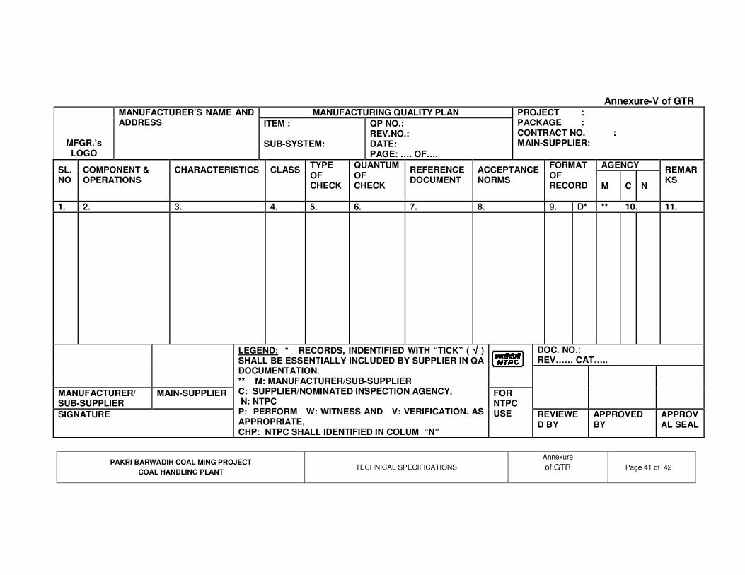
PAKRI BARWADIH COAL MING PROJECT COAL HANDLING PLANT
TECHNICAL SPECIFICATIONS Annexure of GTR
Page 41 of 42
Annexure-V of GTR
MANUFACTURING QUALITY PLAN
MFGR.’s LOGO
MANUFACTURER’S NAME AND ADDRESS ITEM :
SUB-SYSTEM:
QP NO.: REV.NO.: DATE: PAGE: …. OF….
PROJECT : PACKAGE : CONTRACT NO. : MAIN-SUPPLIER:
AGENCY SL. NO
COMPONENT & OPERATIONS
CHARACTERISTICS
CLASS
TYPE OF CHECK
QUANTUM OF CHECK
REFERENCE DOCUMENT
ACCEPTANCE NORMS
FORMAT OF RECORD
M C N
REMARKS
1. 2. 3. 4. 5. 6. 7. 8. 9. D* ** 10. 11.
DOC. NO.: REV…… CAT…..
MANUFACTURER/ SUB-SUPPLIER
MAIN-SUPPLIER
SIGNATURE
LEGEND: * RECORDS, INDENTIFIED WITH “TICK” ( √√√√ ) SHALL BE ESSENTIALLY INCLUDED BY SUPPLIER IN QA DOCUMENTATION. ** M: MANUFACTURER/SUB-SUPPLIER C: SUPPLIER/NOMINATED INSPECTION AGENCY, N: NTPC P: PERFORM W: WITNESS AND V: VERIFICATION. AS APPROPRIATE, CHP: NTPC SHALL IDENTIFIED IN COLUM “N”
FOR NTPC USE REVIEWE
D BY APPROVED BY
APPROVAL SEAL

PAKRI BARWADIH COAL MING PROJECT COAL HANDLING PLANT
TECHNICAL SPECIFICATIONS Annexure of GTR
Page 42 of 42
Annexure-VI of GTR
FIELD QUALITY PLAN
MFGR.’s LOGO
SUPPLIER’S NAME AND ADDRESS ITEM :
SUB-SYSTEM :
QP NO.: REV.NO.: DATE: PAGE: …. OF….
PROJECT : PACKAGE : CONTRACT NO. : MAIN-SUPPLIER:
SLNO
ACTIVITY AND OPERATION
CHARACTERISTICS / INSTRUMENTS
CLASS# OF CHECK
TYPE OF CHECK
QUANTUM OF CHECK
REFERENCE DOCUMENT
ACCEPTANCE NORMS
FORMAT OF RECORD
REMARKS
1. 2. 3. 4. 5. 6. 7. 8. 9. D* 10.
DOC. NO.: REV…… CAT ….
MANUFACTURER/ SUB-SUPPLIER
MAIN-SUPPLIER
SIGNATURE
LEGEND: * RECORDS, INDENTIFIED WITH “TICK” (√) SHALL BE ESSENTIALLY INCLUDED BY SUPPLIER IN QA DOCUMENTATION. LEGEND TO BE USED: CLASS # : A = CRITICAL, B=MAJOR, C=MINOR; ‘A’ SHALL BE WITNESSED BY NTPC FQA, ‘B’ SHALL BE WITNESSED BY NTPC ERECTION / CONSTRUCTION DEPTT. AND ‘C’ SHALL BE WITNESSED BY ERECTION SUPPLIER (A & B CHECK SHALL BE NTPC CHP STAGE)
FOR NTPC USE
REVIEWED BY
APPROVED BY
APPROVAL SEAL
Format No.: QS-01-QAI-P-09/F2-R0 1/1 Engg. Div./QA&I

ENGINEERING PROJECTS (INDIA) LIMITED
Coal Handling Plant Package for
Pakri Barwadih Coal Mining Project of NTPC
PACKAGE No. : ENGG/PA/344/M/1
RAPID LOADING SYSTEM
VOLUME – 2B
TECHNICAL SPECIFICATIONS
CONTENTS
Sl. No. DESCRIPTION Page Nos.
1. Cover page 2
Documents/information to be furnished alongwith offer 3 2.
3. 4 Project Synopsis
4. 6 Scope of Supply Technical Specifications 5. 8
6. Spares 35
7. 39 Reference Drawings
8. 40 Technical data sheet (to be filled by the vendor)
9. Attachment 3A-3 (to be filled by the vendor) 42
1 of 42

Format No : DLI / ENGG / F - 08
ENGINEERING PROJECTS (I) LTD Engineering Division
Pakri Barwadih Mining Project, CHP - NTPC Mechanical 2 of 42
Enquiry Technical Specifications
For
RAPID LOADING SYSTEM
42 Total No of Pages
No. of Drgs. Enclosed 3
PREPARED BY CHECKED BY APPROVED BY
DATE : DATE : DATE :
PROJECT SPECIFICATION NO. REV.NO
Pakri Barwadih Mining Project, CHP-NTPC
ENGG/PA/344/M/1 0
2 of 42

DOCUMENTS/ INFORMATION TO BE FURNISHED ALONGWITH OFFER 1. Clear Scope of supply.
2. Exclusions, if any.
3. Type and quantity of oil, lubricants & consumables for initial fill till successful commissioning of equipment.
4. List of Commissioning spares and start-up spares with unit rates (cost to be included in equipment supply price).
5. List with price of special tools and tackles, if any required (cost to be included in equipment supply price).
6. Price Schedule for equipment, mandatory spares & erection work as per Format enclosed.
7. List of Recommended spares for 3 years trouble free operation and maintenance alongwith unit rates as per format enclosed in price schedule.
8. Technical Data sheets duly filled by the vendor (blank data sheets enclosed ).
9. Duly filled Attachment 3A-3 (blank enclosed) alongwith the certificates from clients.
10. Weight of the equipment in Kgs.
11. Catalogues/ Leaflets and O&M Manuals.
12. Copies of G. A. Drawing of the equipment/ System.
13. Reference list of your Customers for the similar supply of items.
14. Quality Assurance Plan.
15. List of electrical load with kW rating.
16. SLD and interlocking details.
17. Input output list of PLC for rapid loading system and interfacing details to have interface/ communications with main plant PLC system (as shown in enclosed configuration drg. No. 7010-155-PVEB-002, sheet 1 of 2).
18. Silo control work stations and printer connectivity details on dual data communication link (refer configuration drg no. 7010-155-PVEB-002, sheet 1 of 2)
3 of 42

PROJECT SYNOPSIS 1.00.00 BACKGROUND 1.01.00 Pakri Barwadih Block is located in North Karanpura Coalfields in Hazaribagh district
of Jharkhand state, India. The block has been allotted to NTPC Limited by Ministry of Coal, Government of India.
2.00.00 Location and Approach 2.01.01 The Pakri-Barwadih block is located in the north eastern part of North Karanpura
Coal Field, It is bounded by longitudes 850 0 010’ to 85 15’E and latitude 23 51’30” to 23055’30” North and is covered by the Survey of India Topo-sheet no. 73E/1 (R.F 1: 50000) and special sheets no. 21, 23 & 24 ( R.F. 1:10000).
2.01.02 The entire block falls in the Hazaribagh district of Jharkhand State. The nearest township is Hazaribagh located at a distance of around 25 kms from Barkagaon in the southern part of the block. Ranchi, which is the state capital of Jharkhand, is around 120-130 kms from the block.
2.01.03 The Hazaribagh – Khelari – Ranchi State highway passes through the eastern part of
the block touching Barkagaon and Tandwa Villages. This locality is connected from Hazaribagh by an all weather 24 Km metalled road which has been extended along the northern & western part of the coalfield touching Kerendari and Tandwa. This can serve as a useful road link from Pakri-Barwadih to Tandwa where a proposed Super Thermal Power Station of NTPC is also considered to be located.
2.01.04 The nearest rail stations are Ranchi Road and Chitarpur on the Gomoh Barkakana –
Dehri-on-Sone loop lines of South East Railway both around 70- 75 kms from the block.
2.01.05 The coalfield is likely to be connected by a new railway network under initial phases
of execution as described in clause no. 3.01.07 of this chapter. 2.01.06 Further to the information given in this sub-section, Bidders are also advised visit the
project site and collect data on local site conditions. 2.01.07 Information on existing/ planned Indian Railway line in the area :
The existing nearest Railway line to the Pakri – Barwadih coal block is the Barkakana loop popularly known as the CIC loop running between Gomoh – Barkakana – Garhwa Road. Pakri Barwadih Mine block is situated to the North of this railway line. The Railway’s Grand Chord i.e. Gomoh-Koderma-Gaya-Dehri-on-Sone line lies on the North of the said mine. Two new railway links are also under construction around the Pakri-Barwadih and Amrapali Coal Block in North Karanpura area. One rail link is from existing Koderma station on the Grand Chord. It would connect Barkakana station on the CIC section in the South and will extend up to Ranchi. In between Koderma and Barkakana a new junction station viz Hazaribagh would be created. This new rail link from Koderma will also connect Rajgir and Tilaya station in the North. The entire link is the project of East Central Railway. The other rail link will take off from the new Hazaribagh Jn and would connect Tori station on CIC line in the South. This second rail link is being constructed at the cost of Central Coalfield Limited (CCL) to facilitate coal loading from North Karanpura mine area. Shivpur will be an important station over this link to provide rail access to mining area. The Pakri- Barwadih mine block lies in between the above two Rail links i.e. from Hazaribagh to Shivpur and Hazaribagh to Barkakana. The nearest station under construction over the two sections is Banadag station about 7.5 km from Hazaribagh station on Hazaribagh-Shivpur line – proposed formation level at Banadag is about 627 M above MSL. Banadag station is being planned as a 3 lines station over Hazaribagh – Shivpur single line section (about 7 km from Hazaribagh).
4 of 42

2.01.08 Location of Mine Block
Location of Pakri Barwadih Mine Block o oa) Longitude : 85 09’ to 85 15’ E
o o 51’ to 23 55’ 30’’ N b) Latitude : 23 2.01.09 Meteorological Data: The Pakri Barwadih block being a virgin block has no rain
gauging station, The nearest station is at Barkagaon block office, situated in Barkagaon village in the south eastern corner of eastern sector, where daily rain fall is recorded. The rainfall data for the period from 1979-2004 were collected and enclosed at Annex. I.
2.01.10 Water Source: There is no perennial source of water in the area. Thus ground water
needs to be tapped for industrial and domestic use. 2.01.11 Criteria for Wind Resistant Design of Structures and Equipment All structures and
equipment of the coal handling plant including all plant auxiliary structures and equipment, shall be designed for wind forces as given in Civil Specifications.
2.01.12 Criteria for Earthquake Resistant Design of Structures and Equipment All coal
handling plant structures and equipment, including auxiliary structures and equipment shall be designed for relevant seismic forces.
5 of 42

SCOPE OF SUPPLY 1.0 The scope of the work includes Design, engineering, manufacture, shop fabrication.
assembly, testing and inspection at manufacturer’s works, packing , despatch ,transportation, transit insurance, delivery to site, receipt, unloading, handling, storage at site, inplant transportation at site, fabrication at site, installation/Erection and testing & commissioning , completion of facilities, performance guarantee testing, final painting at site and handing over to the Employer of Rapid Loading System as per specifications and scope defined in tender documents complete with all accessories and electricals, which are not mentioned specifically but are required for the efficient and trouble free operation of the equipment/system.
Following items are also included in vendor’s scope.
1.1 Complete Rapid loading system as per the details given in the specifications.
1.2 Consumables like first fill of lubricating oils etc. for the initial operation of the equipment till handing over.
1.3 Commissioning spares and start-up spare parts.
1.4 Special tools & tackles, if any required.
1.5 Mandatory spares as per the list enclosed in Price schedule.
1.6 Recommended spare parts for 3 years trouble free operation and maintenance.
1.7 Painting of complete equipment (Including final painting before handing over to Employer).
1.8 Supervision, erection/Installation, inspection, testing & commissioning at site and handing over to the Employer.
1.9 All drawings / documents along with operation and maintenance manuals as per requirement mentioned elsewhere in the tender document.
1.10 Approval of design/drawings and any other design calculation related to the equipment from EPI / NTPC.
1.11 System voltage shall be 415V ± 10% TPN.
2.0 Broad List of items in vendor’s scope of supply shall be as follows. Broad list of all items from maintenance gates (below silo opening) to wagon loading chute except civil works, have been included in vendor’s scope of supply.
Following items shall be in vendor’s scope of supply exactly as per enquiry
specifications.
a) Maintenance gates–-- 8 nos (hydraulically operated).
b) Silo discharge gates --– 8 nos (hydraulically operated).
c) Pre-weigh bins --– 2 nos alongwith one set of test weights of 18000 kg with each preweigh bin for weigh bin calibration.
d) Flow control gate --– 2 nos (hydraulically operated).
e) Telescopic / swing chute --– 2 nos (hydraulically operated).
f) Air cannon system / Arch breaker --– 20 nos of Air cannons complete with air vessel, dryer, mountings, accessory, interconnecting pipes, air compressor, programmable electronic controller etc.
g) Complete Hydraulic system with piping, valves & fittings etc.--– 2 sets
6 of 42

h) Steel structural supports for all equipment below silo alongwith, nuts, bolts, washers, fixtures, foundation bolts and grouting etc.
i) Interconnecting control cables and their terminations. Power cable shall be provided by EPI however laying & their termination with equipment & MCC shall be in the scope of vendor.
j) MCC Panel shall be provided by EPI however electrical details (rating of each load) to be furnished along with SLD and interlocking details.
k) Instrumentation items:
(i) High temperature detectors & indicators for silo and cables upto the control room for the same shall be in vendor’s scope as per NIT specifications.
(ii) System software and application software for operation shall be in the vendor’s scope.
(iii) Continuous level indicator ultrasonic type (As per the NTPC’s specifications) and cables upto the control roomfor the same shall be in vendor’s scope.
(iv) Silo control room shall have the operating & programming PLC based work stations – 2 nos. and laser colour printer--1 no. Both work stations shall have communication with HMI servers in main control room over dual redundant data communication link. All required hardware and software for establishing communication of Silo PLC with main CHP work stations and Silo control room work stations, control desk, printer , power supply system etc. shall be in vendor’s scope of supply.
(v) Work station monitor size shall be 21” (industrial grade) with membrane key board. CRT shall be IBM compatible, digital colour CRT (multi Sync with 0.25 dots/ inch resolution; CRT shall have graphic display facility.
(vi) Main control desk with stop push buttons for drives / system, mimic and PLC driven annunciation system alongwith mandatory spares shall be in vendor’s scope as per NIT specifications.
(vii) Processors of PLC shall be 2 x 100 % in hot stand by mode.
(viii) PLC system shall be provided with redundant power supply unit.
(ix) Training on system shall be in vendor’s scope and type test reports shall be submitted for PLC system.
(x) Isolation between inputs, outputs and controller of PLC shall be 1.5 KV opto couplers.
(xi) Vendor shall furnish total input / output list for PLC system to have the interfacing with main plant PLC system for operation from Main Control Room.
7 of 42

Technical Specifications
of
RAPID LOADING SYSTEM 1.00.00 GENERAL : The fast loading system shall be installed at the bottom of RCC silo and shall include
but not limited to, silo discharge hoppers, maintenance gates, silo discharge gates, pre-weigh-bins, flow control gates, telescopic /swing chute, calibration weigh system, Air cannon system, Hydraulic system, Silo level indication system and Silo maintenance facility.
2.00.00 SILO DESIGN DATA The silo will be designed for the following :
a) Capacity (live) bulk density 4000 tonne at 0.8 t/m3 b) Self flowing coal volume in the Silo 5000 m3 (min.) c) Maximum weight of coal in the Silo 4315 tonne d) Material size (-) 50 mm
0e) Silo slope angle 67 (minimum) f) No. of outlets for wagon loading Two g) Outlet size for flood loading Suitable for a discharge rate of
7500 tph. h) Diameter of silo 20 m (inside)
3.00.00 Technical Details of Equipment.
3.01.0 Maintenance Gates (8 Nos.)
i) The gates are to be fitted below the underside of the silo and are intended for maintenance/ isolation purposes. The gates will be kept in open position during the entire loading operation and may be closed at the end of each rake loading operation.
ii) The slide gate framework will be manufactured from structural channel of suitable design/size.
iii) The slide doors will be made from 32 mm thick mild steel plates and will be flat. It will be lined with abrasion resistant liner, 10 mm thick 220-240 BHN. It will move on heavy duty needled type cam followers. The cam followers will be located outside the flow of coal and will be easily re-greasable. The leading edges of the slide gate will be chamfered. It will have nominal opening as 1525 x 1525 mm.
iv) The gate operation shall be by a portable hydraulic system v) Operating clearance would be provided above and along the sides of the
doorplates. External grease lubrication facilities would be provided to serve all locating hoses and point needing regular lubrication.
vi) The painting/finish will be in accordance with IS 1477 (Current). Three coats of approved paint would be applied.
8 of 42

3.02.0 Silo Discharge Gates (8 Nos.) i) Eight overlapping double bladed horizontal rolling slide gates 1525 x 1525 mm
nominal opening will be fitted on the eight 1525 mm square opening flanges at the bottom of the silo below the maintenance gates. This would ensure a minimum free fall discharge rate of 12000 TPH. These gates will be control the flow of coal to pre weigh bin. There will be four set of outlets for each pre weigh bin.
ii) The gate framework would be of heavy-duty structural channels rigidly reinforced. The gate blade will be of 32 mm mild steel with 10 mm plug welded abrasion resistant stainless steel liner to 220-240 BHN.
iii) Actuation would be by heavy-duty hydraulic cylinder, cushioned at both ends and suitable mounted on the frame of the gate. Four limit switches will provide position indication.
iv) The gate blade will be mounted on antifriction rollers of needle type Regreasable cam followers shall be located outside the flow of coal.
3.03.0 Pre-Weigh Bin (2 nos.) The arrangement of pre-weigh bin is to be designed to have a nominal flush capacity
of 149 m3. This is to be located below the silo and mounting would be by means of four compression load cells and attached to brackets forming integral part of the weigh bin. Controlled filling of the weigh bin will be by means of four hydraulically operated horizontal rolling slide gates positioned immediately above. The emptying shall be by means of a swing gate at the bottom of the weigh bin. Flexible seals are to be' provided between the silo discharge gates and top of the weigh bin to prevent any interference with the weighing. There will be one outlet for each pre weigh bin. These outlets will be controlled by flow control gates located at the bottom of the swing.
Lifting point to be provided for use during the initial erection of the weigh bin and jacking pockets are to be incorporated adjacent to each load cell for their, lifting and removal for routine maintenance.
The weigh bin will be made of 10 mm thick mild steel plates provided with corner angles and rolled steel section for all conditions of Ioading. The weigh bin will be lined with replaceable 8 mm stainless steel plates. The sloping sides will be at minimum 70 degree to the horizontal.
3.04.0 Flow Control Gate (2 Nos.) This gate will be located at the bottom of the chute and will have a nominal 1525 mm
x 1525 mm internal opening and will be of curved blade non jamming type design. It will have the following specific features. i) The gate wall will be of 12 mm mild steel plates with 10 mm abrasion resistant
steel liner (TISCRAL) to 220-240 BHN plug welded. ii) The curved blade will be of 25 mm mild steel plate with 5 mm thick SS 304 top
liner. iii) The blade will pivot on a shaft supported by two flange bearings with external
lubrication fittings. iv) Actuation will be by two hydraulic cylinders. v) The gate opening can be varied between fully close and fully open position, if
required. Facility shall be kept for providing position feed back. 3.05.00 Telescopic/ Swing Chute (2 Nos.) The telescopic /swing chute with bottom discharge gate would have nominal 1525 x
1525 mm opening and have the following specific features:
9 of 42

i) Chutes wall shall be of 12 mm mild steel plate. The abrasion resistant lining steel plates (TISCRAL) shall be provided at places where coal flow is expected.
ii) The Chutes would pivot in the direction of train travel in case of swing chute. The pivoting action will be such that positive control over positioning of chute with respect to the wagon is possible under all conditions.
iii) Chutes shall have necessary replaceable urethane seal system to minimize dust.
iv) Necessary arrangement shall be provided to give automatic retraction of chute if contact with forward moving wagon or locomotive is made.
v) The chute will have shear section such that in the event of a roll back by the locomotive or a wagon and the chute not retracting in time, the shear bolts would be cut and the lower gate section will merely drop into the wagon safely without any damage to other parts of the chute gate system.
vi) A crushable section will be provided at the lower most section of the chute so that any wagon hitting this section will crush it without causing any other damage to the chute. This crushable section shall be replaceable.
vii) The chute shall be actuated by heavy-duty hydraulic cylinder cushioned at both ends.
viii) The chute shall be capable of being raised to clear position in fully loaded condition also.
3.06.00 Calibration Weight System i) There are two pre weigh bins. One set of test weights of 18000 kg would be
supplied with each pre weigh bin for weigh bin calibration. These weights would be integrally mounted in the weigh system and could be activated by hydraulic cylinders from the control room.
The certified calibration weight shall be in the form of a number of cast iron weights placed symmetrically on either side of the weigh bin. They shall be removed from/applied to the weigh bin by hydraulic power.
The test weights shall be certified and stamped by the Indian weights and measures department, and would be constructed from a material such as cast iron.
ii) The electronic check of the weighing instrumentation would correct any drift of
zero or gain irregularity and this check will be carried out prior to each train loading as part of the automatic initialising procedures.
iii) Weight calibration is to be carried out on a regular weekly basis immediately
before train loading and would be completed in 30 minutes maximum. The frequency of calibration may require to be varied by circumstances and by experience build up, once system is in operation.
3.07.00 (a) Air Cannon System/Arch Breaker To ensure trouble free material flow from the coal silo minimum 20 numbers of Air
Cannons are to be provided. The Air Cannon would be complete with air vessel, dryer, mountings, accessory package and inter connecting piping etc.
The Air Cannons would be of tried and proven design and would have discharge
valve assembly suitably mounted to the Vessel with metallic piston and high
10 of 42

temperature resistant soft seat. The entire Air Cannon would be suitable for sustained temperature of minimum 150 degree C that may be encountered if hot coal is contained in the silo, which may raise the temperature in areas adjacent to the Air Cannon. Air Cannons are to be provided as follows: i) Air Cannons of minimum 625 litre capacity would be mounted on the concrete
portion of the silo in two levels. ii) Location and firing sequence, however, is to be decided during detail design
stage. Each Air Cannon would consist of a reservoir tank to store air under pressure with
suitable discharge valve assembly. On command through a programmable electronic controller energising solenoid valve, a given quantity of air would suddenly be injected into the stuck up material, to help flow of material.
The air Canon Vessel should be fabricated from boiler quality plates to IS2002 and
will be designed as per IS 2825 code for unfired pressure vessels. The vessel shall be painted with corrosion resistant, epoxy paint on inside surfaces over one coat of epoxy primer and one coat of red oxide primer followed by two coats of synthetic enamel over external surfaces. The discharge valve Assembly shall be of carbon steel with chrome plating on inner surface and must be mounted suitably to the Air Cannon Vessel for ease of maintenance and cleaning of piston without dismantling the Air Cannon. Size of Air Cannon discharge should be minimum 100 mm NB with free flow area at all points corresponding to 100 mm diameter.
Each Air Cannon should be provided with safety valve, drain plugs, quick exhaust
valve. The quick exhaust valve would be connected to the Air Cannon by means of suitable flexible hose with stainless steel wire braiding.
The Accessory Package for each Air Cannon shall consist of 3-way solenoid valve. Ball Valve, Check Valve, Air Filter, Air lubricator and connecting Hose.
Each Air Cannon would have a suitable designed mounting package for mounting on
the silo with minimum 100 mm FB pipe complete with mounting plant, a pair of forged flanges, nuts, bolts and gaskets.
Operation of the Air Cannon system will be automatic by means of a programmable
electronic controller with an adjustable firing time of 0-99 seconds, between firings, and 0 to 24 hours adjustable cycle time. The timer would be fitted with manual bypass arrangement for individual circuits. The controller would have LED display to indicate individual circuit fired condition.
Compressed air will be supplied at pressure of approximate 7 kg/sq.cm. However, air
cannons would be suitable for maximum working pressure of 9 kg/sq.cm. and hydraulically tested at 13.25 kg/sq.cm.
(b) Air Compressor Two (2) nos. 100% capacity (one working & one standby) screw compressor having
capacity of 100 cum per hour at a discharge pressure of 8.5 kg / cubic meter. The compressor shall be complete with 5 cubic meter. minimum capacity of air receiver, inter cooler, after cooler and all inter connecting pipe work. The compressor shall be driven by suitable totally enclosed fan cooled squirrel cage induction motor to suit 3- phase 50-cycle 415V supply. All necessary air filters, pressure gauges, safety valves, non-return valve, low oil and water pressure switches, pressure reducing valve, etc. shall be provided.
11 of 42

The compressor shall be capable for working at an altitude of 100 mtr. and above see level at maximum ambient temperature of 50 degree and 100% humidity. Air supply is not required to be oil free as some lubrication is desirable for operation of the air blaster.
3.08.00 High Temperature Detection For heat detection, minimum (30) thirty temperature sensors are to be embedded in
the silo inside walls at three levels to detect any local heating and to give a warning in the loading control room and at the main control room. In the event of over heating being detected, the system will provide audible and visual warning to enable the loading major supervisor to take preventive action before a major fire occurs. The system must have battery back up to operate even in the event of power shut down or failure and be of proven type for similar duty application.
The complete system shall be provided with cables from sensors to control room, required conduit and indication unit in control room.
3.09.00 Hydraulic Equipment
i) Two(2) sets of hydraulic system shall be provided, one set for each of the two
loading systems within the silo. Each hydraulic system shall be served by separate hydraulic power pack. The two power packs shall be identical. Each power pack should be capable to operate the hydraulic cylinders of the following equipment:
a) 4 Nos. silo discharge gates.
b) 1 No. the swing chute.
c) 1 No. the flow control gate
d) 2 sets of calibration weights on weigh bin.
ii) The complete system shall be sized to provide sufficient rapid action at all cylinder to achieve the required equipment closing times. These times must satisfy the fastest duty cycle, which is likely to occur when the coal is in its best state for flow and the train is over-speeding to maximum tolerance allowed. All equipment shall be rated for continuous duty in the range of climatic conditions prevailing at the site.
iii) The loading system shall be provided with a independent hydraulic accumulator station having sufficient capacity so that in the event of total power failure, closing of the silo discharge gates, the flow control gate and raising of loading chute to high level as desired could still be achieved.
vi) The power pack reservoir capacity, type and size of pump, size of motor operating and test pressure, type of oil etc. shall be designed to suit the required duty of the system. Each power pack will be completed with all necessary pipe work fittings and valves etc. The power packs shall incorporate an oil cooler, in view of high ambient air temperature. Cross over facilities between the two power packs are to be provided for stand by purposes.
v) The hydraulic system will be controlled from the central microprocessor based weighing loading control system located in the silo control room. Provision is to be made for the system to react to operating signals from this control room, and the return system status information for displaying in the control panel. The system shall be designed for fail to safe operation. Hydraulic fluid used will be fire resistant type.
12 of 42

3.10.00 Level Indication inside Silo
The level indicators provided shall monitor the following:
i) Continuous level of coal in the silo
ii) Pre-determined high coal level in the silo, which will automatically stop the silo in feed conveyor. This will also ensure that coal in the highest position will not touch structures on top of the silo.
iii) Pre determined intermediate level. Pre determined low level in the silo, which will automatically close the silo outlet gates. It may be just above the RCC cross mounts inside the silo. This is to prevent damage to any RCC work and the silo outlet gates. The gates will remain closed and inoperative until pre determined intermediate level of coal is reached.
The equipment will be ultra sonic type complete with sensors, transmitter and limit controllers together with audio-visual signaling system for different levels. In addition to the direct reading device, comparator shall also be incorporated to detect excessive differential levels across the silo which may occur in the event of certain adverse flow conditions. This will initiate an audio-visual signal to alarm the supervisor and enable him to initiate necessary measures. Continuous silo level/high/low level indication and alarm/annunciation shall be available both in the silo control room as well as CHP control room.
All required cables from sensors/transmitters to control room indicators & conduits as required shall be provided.
3.11.00 Silo control room shall be provided for fast loading silo. The silo control room shall be located to give the operator full view of the loading operation. The silo operation shall be controlled through control desk provided in the silo control room. The silo control room shall be air-conditioned. Vendor to indicate size and control room.
Facility for printout of silo pre-weigh system as well as in motion weigh bridges shall be available in the silo control room. This data shall also be available in the main CHP control room.
3.12.0 Control Desk
Main control desk
Mosaic based control desk type for mounting push buttons/metres etc. with doors at the rear. The mosaic grid tiles shall be of 24mmx48mm (or 25mmx50mm) size, made of heat and flame retardant, self-extinguishing and non-hygroscopic material with flat-matt finish without glare and non-reflecting type. PC based OWS (Operator Work Station) of PLC shall be mounted on control desk to house PC/ keyboards/ mouse etc. The profile and dimension shall be decided during detailed engineering and shall be subject to Employer’s approval.
Necessary controls, indications and annunciations for all the above equipment shall also be provided in main control desk as described elsewhere.
3.13.00 SILO CONSTRUCTIONAL DETAILS (Silo construction is not in bidder’s scope of supply)
The RCC silo will be designed on “Mass Flow” basis for the material to be handled, such that the chances of bridging or arching over the silo outlets are reduced to a minimum.
One railway track will be passing under the silo. The scope of civil works will also include the necessary drainage, leveling and grading up to 15 meters all around the silo portion.
13 of 42

The silo hopper will have minimum 67 degree slope to the horizontal. The hopper portion will be provided with stainless steel liner with 8mm thickness of hardness 220 – 240 BHN. The vertical portion will be provided with 25 mm thick ironite lining of suitable specifications.
The 8 (Eight) numbers Silo Discharge RCC Hoppers at the bottom of the RCC silo will be made of 20 mm thick mild steel plate and lined with stainless steel liner of 8 mm thickness of hardness 220-240 BHN.
The hoppers will be properly grouted with the mother RCC of the silo with suitable reinforcement, capable to support a minimum load of 94 Te for each hopper. Staircase and lift approach will be provided at all working levels of silo and up to the top of the silo. The top of silo will be covered and provided with handrail. The equipment necessary for periodical inspection of silo from in side and out side will be provided. The coal sampling system equipment for the belt conveyers feeding the silo will be installed at the top of silo.
14 of 42
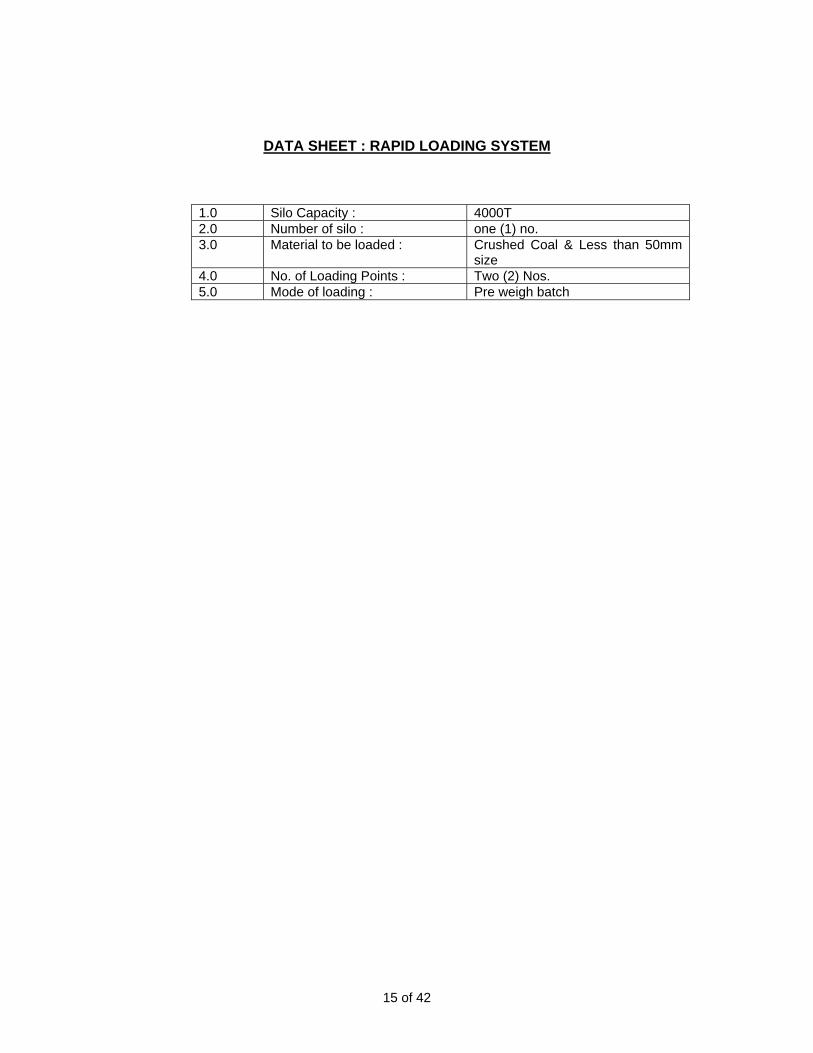
DATA SHEET : RAPID LOADING SYSTEM
1.0 Silo Capacity : 4000T 2.0 Number of silo : one (1) no. 3.0 Material to be loaded : Crushed Coal & Less than 50mm
size 4.0 No. of Loading Points : Two (2) Nos. 5.0 Mode of loading : Pre weigh batch
15 of 42

GUARANTEE TEST PROCEDURE 2.03.16 Rapid Loading System
i) Demonstration of operation of maintenance gate, silo discharge gates, flow control gates
ii) Demonstration of batching process. iii) Satisfactory operation of Telescopic / swing chute. iv) Demonstration of mass flow in silo in rainy season. v) Demonstration of fast loading at specified rate without any coal spillage
2.03.17 Equipment Testing Rapid Loading system discharge rate = 7500 tph
16 of 42

DESIGN PARAMETERS
2.10.00 Loading Silo
The silo will be designed for the following:
3a) Capacity (live) bulk density 4000 tonne at 0.8 t/mb) No. of silos 1 no. c) Material size (-) 50 mm
0 d) Silo slope angle 67 (minimum) e) No. of outlets for wagon loading 2 Nos. f) Outlet size of flood loading Suitable for a discharge rate of
5500 – 9200 tph. g) Diameter of silo. 20 m (inside)
2.10.01 All equipment under the scope shall be suitable to the system capacities parameters
as specified in the technical specifications of rapid loading system.
17 of 42

QUALITY ASSURANCE REQUIREMENT 1.20.00 Rapid Loading System 1.20.01 Gates/Chutes
a) All plates equal to or above 25mm thickness shall be ultrasonically tested. b) Following minimum NDT requirements to be carried out for welds:
i) Butt welds - 10% UT/RT and 100% MPI/DPT. ii) Fillet Welds - 10% MPI/DPT.
c) Functional checks on the slide and other gates shall be carried out alongwith
respective hydraulic cylinder, if applicable. 1.20.02 Air Canon System 1.20.02 (a) Air Compressor
i. Air Compressor - In addition to Hydraulic tests of pressure parts, performance
run test of the compressor shall be done for FAD, pressure, , power consumption, as per relevant code.
ii. All pressure parts of Air Cannon system shall be hydraulically / pneumatically
tested iii. Assembled Air cannons shall be subjected to functional / performance test
1.20.03 Hydraulic System 1.20.03 (a) The hydraulic system and its constituent items for various gates operation
consisting of Hydraulic Cylinders, Hydraulic Power Packs, Hydraulic Pumps and motors, Hydraulic Pipes & Valves etc. shall be subjected to pressure test, functional test as applicable.
18 of 42

CONVEYOR PARAMETERS (Conv. feeding to silo)
1 Conveyor No. 7A/7B
2 Capacity
Rated 2500 TPH
Designed 2750 TPH
3 Belt Width 1800 mm
4 Belt Speed 3.2 M/sec. (Min.) 05 Troughing angle 35
19 of 42

SYSTEM DESIGN BASIS 3.00.00 SYSTEM DESIGN BASIS 3.01.00 The rated capacity of the Belt Conveyors shall be 2500 TPH. The mechanical and
structural / civil system shall be designed for 2750 TPH capacity and round the clock operation with both the streams operating simultaneously throughout the year.
3.02.00 Following shall be considered while designing the Equipment :
a) The Coal conveyed shall be of size (-) 50 mm & below. However occasionally
1-2% coal of 150 mm lump size may also be encountered. b) HGI of the Coal shall be between 44 to 65. Normally moisture content in coal
will vary between 12% to 15%. However for design purposes, moisture content of 20% shall be considered.
c) Due to open cast method of mining involved, the coal may occasionally contain
metal pieces like broken shovel teeth, brake shoe, wires etc. d) The “as received” coal shall contain varying percentage of fines. Coal with such
fines may tend to form adhesive lumps, particularly during monsoon when surface moisture is at its maximum value.
e) The sizing and selection of the vital equipment covered under the scope shall
be based on the above characteristic of coal and operating conditions. Vendor shall ensure that equipment/ system efficiency shall not be affected particularly during monsoon when surface moisture is at its maximum value.
3.03.00 For the purpose of volumetric computation, the bulk density of the coal shall be taken
as 800 kg/ m3. Therefore for calculation of belt conveyor capacity, for their drives & drive motors kW requirement, and sizing (volume calculations) of chute, hoppers etc. the above bulk density shall be considered. For all other purposes viz. for stresses/ load on structures sizing of actuators for flap gates, gate calculations of plugged chute/ hopper loads etc. the bulk density of the coal shall be taken as 1100 kg/ m3.
3.04.00 All mechanical, and structural / civil system design shall consider simultaneous
running of both the streams at rated load, starting of one stream with the other stream in standstill condition as well as starting of one stream with the other stream in operation.
20 of 42

SPECIAL CLEANING, PROTECTION AND PAINTING All equipment’s of Coal Handling Plant inclusive of belt conveyor system and technological structures shall be kept clean. Surfaces to be painted shall be thoroughly cleaned of loose mill scale, rust etc. by wire brushing. All ferrous surfaces shall be applied with one shop coat of 35 micron and one 35 micron site coat of red oxide zinc chromate and two coats, each of 25 micron, synthetic enamel finishing paints unless specified otherwise. A minimum of 120 microns Dry Film Thickness (DFT) after finished coat of paint shall be ensured. The painting colour code shall be provided to the vendor during detailed engineering.
21 of 42

DRIVE EQUIPMENT 1.00.00 GENERAL
Suitable Drive Chain Equipment like electric motors, gearboxes (where applicable), fluid couplings (where applicable), flexible couplings and other accessories shall be provided for all the belt conveyors, various pumps of dust suppression system, fans for ventilation system, monorail electrical hoists and other equipment’s specified in this specifications. Various requirements as spelt out in the Technical Specifications for individual equipment shall be taken into consideration while designing the associated drive chain equipment.
2.00.00 CODES AND STANDARDS
The design, manufacture, inspection and testing of Drive Equipment shall comply with all the currently applicable statutes, regulations and safety codes in the locality where the equipment in to be installed. The Drive Equipment’s shall conform to the latest edition of the following standards and codes. Other internationally acceptable standards/codes, which ensure equal or higher performance than those, specified, shall also be accepted. Nothing in this specification shall be construed to relieve the vendor of the required statutory responsibility. In case of any conflict in the standard and this specification, the decision of the Engineer shall be final and binding.
IS:3688 : Dimensions for shaft ends IS:3681: General plan for spur & helical gears IS:7403 : Code of practice for selection of standard worm and helical gear boxes
3.00.00 DESIGN AND CONSTRUCTION REQUIREMENTS
3.01.00 GEAR BOXES
3.01.01 Gear Boxes shall be of sealed type and mounted on machined or ground surfaces.
3.01.02 The gearboxes shall be designed for 24 hours continuous duty in very dusty conditions. For thermal and mechanical rating of the gearbox the data sheet shall be referred to. Gearboxes with cooling coils are not acceptable.
3.01.03 The gears used shall be helical conforming to IS:3681 (latest revision) or worm reduction units or spiral bevel speed reduction units conforming to suitable Indian Standards. The dimensions of the shaft end shall conform to IS:3688 or its latest revision. Above 30 HP drive rating, all gearboxes shall be helical or bevel helical type only.
3.01.04 Recommended oil grade shall be compatible with gear internals like material of bearing, cages. Further, all gearboxes shall have suitable breather plugs, dipstick, drain plug etc.
3.02.00 Couplings
3.02.01 Flexible / Rigid Couplings
Approved type of couplings shall be used for power transmission depending upon duty requirements. The design of the coupling shall be such that it can take shock and misalignment without sacrificing its efficiency. Geared type flexible coupling shall be used on low speed side for all conveyors and other drive chains where gear box is provided. Other couplings in the drive chains shall be either rigid or flexible type, depending upon the requirement of equipment design and shall be finalized during detailed engineering.
22 of 42

3.02.02 Fluid Couplings
Fluid couplings shall be provided in all the drive machinery for belt conveyor systems if the actual power requirement at motor output shaft is more than 40 kW. The fluid coupling for LT motors shall be of traction type. Cooling water coils for traction type fluid coupling shall not be accepted. Scoop tube type fluid coupling shall be provided for conveyors with HT motors. Suitable electrically operated actuators shall be provided for scoop tube operation from local as well as remote. Suitable provision for alternate manual operation shall also be kept. Separate pump with motor shall necessarily be provided for circulating the fluid coupling oil through oil cooler. Independent arrangement for forced cooling water supply using 2X100% capacity pumps to oil cooler shall be provided by Vendor. Suitable interlock using flow switches shall be provided in both oil as well as water lines to trip the drive motor in the event of flow in either lines falling below/ acceptable levels. Suitable pressure indicators and flow indicators shall be provided in the cooling water lines along with all-relevant valves, strainers and accessories. Necessary isolation valves shall be provided in the oil / water line for maintenance of any equipment in the line. Necessary interlock shall also be provided so that the HT motor cannot be started from remote / local unless position of scoop tube permits no load start of the motor. Tripping of downstream equipment while the system is under normal operation shall result in scoop tube re-positioning to permit no load run of the concerned HT motor. Temperature switch shall be provided in the oil circuit and shall trip the system in case of high oil temperature.
Selection of rating & speed of actuator for scoop type fluid coupling shall be made taking into consideration the coasting time of down stream and up stream conveyors and the engagement/disengagement time achievable. The scoop tube operation must be such so to ensure quick draining out of oil from the operating circuit.
23 of 42

DATA SHEET : DRIVE EQUIPMENT 1.0.0 GENERAL 1.1.0 Continuous Motor Rating (Name Plate Rating) at 50 Degree Centigrade Ambient temp. for Electric Motors a) For conveyors of belt conveyor systems and *120% of actual power at belt for In line magnetic separator drive motor output shaft at specified design capacity b) Mono-rail hoists (travel and hoisting), *110% of actual power elevators, all the drives in coal sampling units, requirement at drive motor various pumps of DS systems, service water output shaft at guaranteed systems, cooling water system, potable & Fire (rated) capacity. water system.
c) Ventilation Fans *110% of actual power requirement at drive motor output shaft at guaranteed (rated) capacity. In case of belt drive, the efficiency of transmission shall be considered as 95%.
*The actual power at drive motor output shaft shall be calculated after considering all the losses of down the line equipment’s of the drive train. 1.2.0 Drive Equipment Rating
a) For Conveyors 120% of actual design requirement b) Other Equipment 1 x 100 % duty 120% of actual design requirement c) Other Equipment 2 x 50 % duty 110 % of actual design
requirement 2.0.0 DESIGN & CONSTRUCTION REQUIREMENT 2.1.0 Gear Box 2.1.1 Type
(a) Below 30 HP Helical, worm, bevel as per requirement without cooling coil (b) Above 30 HP Helical / bevel helical without
cooling coil 2.1.2 Service Factor minimum Service factor of gear box shall be
as per accepted engineering practice / manufacturer’s recommendations.
o2.1.3 Ambient temperature for Thermal rating 50 C Minimum
24 of 42

2.1.4 Mounting On Machined/Ground Surfaces 2.1.5 Output Rating a) For belt conveyor systems Service factor of gear box shall be
as per accepted engineering practice / manufacturer’s recommendations.
b) For other equipment Service factor of gear box shall be
as per accepted engineering practice / manufacturer’s recommendations.
2.1.6 Duty 24 Hrs. Continuous 2.2.0 Flexible Couplings 2.2.1 Type Geared capacity. 2.2.2 Rating Not less than motor rating. 2.3.0 Fluid Couplings For all motors having rating more than 40 KW. 2.3.1 Type (a) L.T. Motors Traction type (b) H.T. motors Scoop tube type. 2.3.2 Rating Not less than motor rating
25 of 42

MOTORS
1.00.00 GENERAL REQUIREMENTS
1.01.00 For the purpose of design of equipment/systems, an ambient temperature of 50 deg. Centigrade and relative humidity of 95% shall be considered. The equipment shall operate in a highly polluted environment.
1.02.00 All equipments shall be suitable for rated frequency of 50 Hz with a variation of +3%& -5%, and 10% combined variation of voltage and frequency.
1.03.00 Vendor shall provide fully compatible electrical system, equipments, accessories and services.
1.04.00 All the equipment, material and systems shall, in general, conform to the latest edition of relevant National and international Codes & Standards, especially the Indian Statutory Regulations.
1.05.00 The auxiliary AC voltage supply arrangement shall have 6.6 kV and 415V systems. It shall be designed to limit voltage variations as given below under worst operating conditions:
(a) 6.6 kV +/- 6%
(b) 415/240V +/- 10%
1.06.00 The voltage level for motors shall be as follows :-
a) Upto 0.2KW : Single phase 240V AC / 3 phase 415V AC
b) Above 0.2KW and upto 200KW : 3 phase, 415V AC
1.07.00 Fault level shall be limited to 40kA RMS for 1 second for 6.6 kV system and 45 kARMS for 1 second for 415V system. 415V system shall be solidly grounded and 110 VDC system shall be isolated type.
1.08.00 Paint shade shall be as per RAL 5012 (Blue).
1.09.00 The responsibility of coordination with electrical agencies and obtaining all necessary clearances shall be of the contractor.
1.10.00 Degree of protection for various enclosures as per IS:13947 shall be as follows :- i) Indoor motors - IP 54 ii) Outdoor motors - IP 55
2.00.00 CODES AND STANDARDS 1) Three phase induction motors : IS:325, IEC:60034 2) Single phase AC motors : IS:996, IEC:60034 3) Crane duty motors : IS:3177, IEC:60034 4) DC motors/generators : IS:4722 3.00.00 TYPE 3.01.00 AC Motors:
(a) Squirrel cage induction motor suitable for direct-on-line starting. (b) Crane duty motors shall be slip ring/ squirrel cage Induction motor as per the
requirement. 3.02.00 DC Motors : Shunt wound.
26 of 42

4.00.00 RATING (a) Continuously rated (S1). However, crane motors shall be rated for S4 duty,40%
cyclic duration factor. (b) Whenever the basis for motor ratings are not specified in the corresponding
mechanical specification sub-sections, maximum continuous motor ratings shall be at least 10% above the maximum load demand of the driven equipment under entire operating range including voltage and frequency variations.
5.00.00 TEMPERATURE RISE Air cooled motors 70 deg. C by resistance method for both class B&F insulation. Water cooled 80 deg. C over inlet cooling water temperature mentioned elsewhere, by resistance
method for both class B&F insulation.
6.00.00 OPERATIONAL REQUIREMENTS
6.01.00 Starting Time
6.01.01 For motors with starting time upto 20 secs. at minimum permissible voltage during starting, the locked rotor withstand time under hot condition at highest voltage limit shall be at least 2.5 secs. more than starting time.
6.01.02 For motors with starting time more than 20 secs. and upto 45 secs. at minimum permissible voltage during starting, the locked rotor withstand time under hot condition at highest voltage limit shall be at least 5 secs. more than starting time.
6.01.03 For motors with starting time more than 45 secs. at minimum permissible voltage during starting, the locked rotor withstand time under hot condition at highest voltage limit shall be more than starting time by at least 10% of the starting time.
6.01.04 Speed switches mounted on the motor shaft shall be provided in cases where above requirements are not met.
6.02.00 Torque Requirements
6.02.01 Accelerating torque at any speed with the lowest permissible starting voltage shall be at least 10% motor full load torque.
6.02.02 Pull out torque at rated voltage shall not be less than 205% of full load torque. It shall be 275% for crane duty motors.
6.03.00 Starting voltage requirement
(a) 85% of rated Voltage upto 1500KW motors
7.00.00 DESIGN AND CONSTRUCTIONAL FEATURES
7.01.00 Suitable single-phase space heaters shall be provided on motors rated 30KW and above to maintain windings in dry condition when motor is standstill. Separate terminal box for space heaters & RTDs shall be provided.
7.02.00 All motors shall be either Totally enclosed fan cooled (TEFC) or totally enclosed tube ventilated (TETV) or Closed air circuit air cooled (CACA) type.
7.03.00 Winding and Insulation (a) Type : Non-hygroscopic, oil resistant, flame resistant
27 of 42

(b) Starting duty : Two hot starts in succession, with motor initially at normal running temperature. However, conveyor motors shall be suitable for 3 consecutive hot starts followed by one hour interval at standstill with maximum 20 starts per day and minimum 20,000 starts during life time of motor.
(d) 240VAC, : Class B or better 415V AC & 220V DC motors
( e) Short circuit rings of conveyor motors shall be either jointless or welded type. Brazed joint is not acceptable.
7.05.00 Motors with heat exchangers shall have dial type thermometer with adjustable alarm
contacts to indicate inlet and outlet primary air temperature. 7.06.00 Noise level for all the motors shall be limited to 85dB(A) except for BFP motor for
which the maximum limit shall be 90dB(A). Vibration shall be limited within the limits prescribed in IS:12075 . Motors shall withstand vibrations produced by driven equipment.
7.08.00 Motor body shall have two earthing points on opposite sides. 7.10.00 The spacing between gland plate & centre of terminal stud shall be as per Table-I. 7.11.00 All motors shall be so designed that maximum inrush currents and locked rotor and
pullout torque developed by them at extreme voltage and frequency variations do not endanger the motor and driven equipment.
7.12.00 The motors shall be suitable for bus transfer schemes provided on the 6.6 KV /415V systems without any injurious effect on its life.
7.15.00 The size and number of cables (for LT motors) to be intimated to the successful bidder during detailed engineering and the contractor shall provide terminal box suitable for the same.
7.16.00 The ratio of locked rotor KVA at rated voltage to rated KW shall not exceed the following (without any further tolerance) except for BFP motor. (a) Upto 110KW : 11.0 (b) Above 110KW & upto 1500KW : 10.0
8.00.00 TYPE TESTS 8.02.00 LT Motors
8.02.01 LT motors shall be of type tested quality. For each type & rating of LT motors rated above 50 KW, the contractor shall submit for Owner's approval the reports of all the type tests as per relevant standards and carried out within last five years from the date of bid opening. These reports should be for the tests conducted on the equipment similar to those proposed to be supplied under this contract and the test(s) should have been either conducted at an independent laboratory or should have been witnessed by a client.
8.02.02 In case the Vendor is not able to submit report of the type test(s) conducted within last five years from the date of bid opening, or in case the type test report(s) are not found to be meeting the specification requirements, the Vendor shall conduct all such tests under this contract free of cost to the Owner and submit the reports for approval.
8.03.00 All acceptance and routine tests as per the specification and relevant standards shall be carried out. Charges for these shall be deemed to be included in the equipment price.
28 of 42

TABLE – I
DIMENSIONS OF TERMINAL BOXES FOR LV MOTORS Motor MCR in KW Minimum distance between centre of
stud and gland plate in mm.UP to 3 KW As per manufacturer's practice. Above 3 KW - upto 7 KW 85 Above 7 KW - upto 13 KW 115 Above 13 KW - upto 24 KW 167 Above 24 KW - upto 37 KW 196 Above 37 KW - upto 55 KW 249 Above 55 KW - upto 90 KW 277 Above 90 KW - upto 125 KW 331 Above 125 KW-upto 200 KW 203 Note: Minimum inter Phase and Phase – earth air clearances for LT motors with
lugs installed shall be as follows:
Motor MCR in KW Clearances in T-bonesUP to 110 KW 10mm Above 110 KW and upto 150 KW 12.5mm Above 150 KW 19mm
29 of 42
CONTROL CABLES
1.00.00 CODES & STANDARDS
1.01.00 All standards, specifications and codes of practice referred to herein shall be the latest editions including all applicable official amendments and revisions as on date of opening of bid. In case of conflict between this specification and those (IS : codes, standards, etc.) referred to herein, the former shall prevail. All the cables shall conform to the requirements of the following standards and codes : IS :1554 –I PVC insulated (heavy duty) electric cables for working voltages upto and including 1100V. IS : 3961 Recommended current ratings for cables IS : 3975 Low carbon galvanised steel wires, formed wires and tapes for armouring of cables. IS : 5831 PVC insulation and sheath of electrical cables. IS : 8130 Conductors for insulated electrical cables and flexible cords. IS : 10418 Specification for drums for electric cables. IS : 10810 Methods of tests for cables. ASTM-D – 2843 Standard test method for density of smoke from the burning or decomposition of plastics. IEC-754 (Part-I) Tests on gases evolved during combustion of electric cables. IEC-332 Tests on electric cables under fire conditions. Part-3:Tests on bunched wires or cables (Category-B).
2.00.00 TECHNICAL REQUIREMENTS
2.01.00 The cables shall be suitable for laying on racks, in ducts, trenches, conduits and under ground buried installation with chances of flooding by water.
2.02.00 Cables shall be Armoured, flame retardant, low smoke (FRLS) type designed to withstand all mechanical, electrical and thermal stresses develop under steady state and transient operating conditions as specified elsewhere in this specification.
2.03.00 Conductor of control cables shall be made of stranded, plain annealed copper.
2.04.00 PVC insulation shall be suitable for continuous conductor temperature of 70 deg C and short circuit conductor temperature of 160 deg. C.
2.05.00 The cable cores shall be laid up with fillers between the cores wherever necessary. It shall not stick to insulation and inner sheath. All the cables, other than single core unarmoured cables, shall have distinct extruded PVC inner sheath of black colour as per IS: 5831.
2.06.00 For multicore armoured cables, the armouring shall be of galvanised steel as follows:
Calculated nominal dia of cable under armour Size and Type of armour Upto 13 mm 1.4mm dia GS wire Above 13 upto 25 mm 0.8 mm thick GS formed wire / 1.6 mm dia GS wire Above 25 upto 40 mm 0.8mm thick GS formed wire / 2.0mm dia GS wire Above 40 upto 55mm 1.4 mm thick GS formed wire/2.5mm dia GS wire Above 55 upto 70 mm 1.4mm thick GS formed wire / 3.15mm dia GS wire Above 70mm 1.4
30 of 42

mm thick GS formed wire / 4.0 mm dia GS wire The gap between armour wires / formed wires shall not exceed one armour wire / formed wire space and there shall be no cross over / over-riding of armour wire / formed wire. The minimum area of coverage of armouring shall be 90%. The breaking load of armour joint shall not be less than 95% of that of armour wire / formed wire. Zinc rich paint shall be applied on armour joint surface.
2.07.00 Outer sheath shall be of PVC as per IS: 5831 and grey in colour. In addition to meeting all the requirements of Indian Standards referred to, outer sheath of all the cables shall have the following FRLS properties.
(a.) Oxygen index of min. 29. (As per IS 10810 Part-58)
(b.) Acid gas emission of max. 20% (As per IEC-754-I)
(c.) Smoke density rating shall not be more than 60% during Smoke Density
Test as per ASTMD-2843.
2.08.00 Cores of the cables of upto 5 cores shall be identified by colouring of insulation. Following colour scheme shall be adopted.
1 core - Red, Black, Yellow or Blue
2 core - Red & Black
3 core - Red, Yellow & Blue
4 core - Red, Yellow, Blue and Black
5 core - Red, Yellow, Blue, Black and Grey
2.09.00 For cables having more than 5 cores, core identification shall be done by numbering the insulation of cores sequentially, starting by number 1 in the inner layer (e.g. say for 10 core cable, core numbering shall be from 1 to 10). The number shall be printed in Hindu-Arabic numerals on the outer surfaces of the cores. All the numbers shall be of the same colour, which shall contrast with the colour of insulation. The colour of insulation for all the cores shall be grey only. The numerals shall be legible and indelible. The numbers shall be repeated at regular intervals along the core, consecutive numbers being inverted in relation to each other. When the number is a single numeral, a dash shall be placed underneath it. If the number consists of two numerals, these shall be disposed one below the other and a dash placed below the lower numeral. The spacing between consecutive numbers shall not exceed 50 mm.
2.10.00 In addition to manufacturer's identification on cables as per IS, following marking shall also be provided over outer sheath:
(a.) Cable size and voltage grade - To be embossed
(b.) Word 'FRLS' at every 5 metre - To be embossed
(c.) Sequential marking of length of the cable in metres at every one metre - To be embossed / printed.
The embossing / printing shall be progressive, automatic, in line and marking shall be legible and indelible.
2.11.00 All cables shall meet the fire resistance requirement as per Category-B of IEC-332 Part-3.
31 of 42

2.12.00 Allowable tolerances on the overall diameter of the cables shall be +\-2 mm maximum over the declared value in the technical data sheets.
2.13.00 In plant repairs to the cables shall not be accepted. Pimples, fish eye, blowholes etc. are not acceptable.
2.14.00 Cable selection & sizing Control cables shall be sized based on the following considerations:
(a) The minimum conductor cross-section shall be 1.5 sq.mm.
(b) The minimum number of spare cores in control cables shall be as follows: No. of cores in cable Min. No. of spare cores 2C, 3C NIL 5C 1 7C-12C 2 14C & above 3
2.14.01 Cable lengths shall be considered in such a way that straight through cable joints are avoided.
3.00.00 CONSTRUCTIONAL FEATURES
3.01.00 1.1 KV Grade Control Cables shall have stranded copper conductor and shall be multicore PVC insulated, PVC inner sheathed armoured FRLS, PVC outer sheathed conforming to IS: 1554. (Part-I).
4.00.00 CABLE DRUMS
(a.) Cables shall be supplied in non-returnable wooden or steel drums of heavy construction. The surface of the drum and the outer most cable layer shall be covered with water proof cover. Both the ends of the cables shall be properly sealed with heat shrinkable PVC/ rubber caps secured by 'U' nails so as to eliminate ingress of water during transportation, storage and erection. Wood preservative anti-termite treatment shall be applied to the entire drum. Wooden drums shall comply with IS: 10418.
(b.) Each drum shall carry manufacturer's name, purchaser’s name, address and contract number, item number and type, size and length of cable and net gross weight stenciled on both the sides of the drum. A tag containing same information shall be attached to the leading end of the cable. An arrow and suitable accompanying wording shall be marked on one end of the reel indicating the direction in which it should be rolled.
(c.) The standard drum length for control cables shall not be less than 1000 metres. The length per drum shall be subjected to a maximum tolerance of +/- 5% of the standard drum length. The Employer shall have the option of rejecting cable drums with shorter lengths. For each size, the variance of total quantity, adding all the supplied drum lengths, from the ordered quantity, shall not exceed +/- 2%.
5.00.00 TESTS
(a) All equipments to be supplied shall be of type tested quality. The Contractor shall submit for Owner's approval the reports of all the type tests as listed in this specification and carried out within last five years from the date of bid opening. These reports should be for the tests conducted on the equipment similar to those proposed to be supplied under this contract and the test(s) should have been either conducted at an independent laboratory or should have been witnessed by a client.
32 of 42
(b) In case the Contractor is not able to submit report of the type test(s) conducted within last five years from the date of bid opening, or in case the type test report(s) are not found to be meeting the specification requirements, the Contractor shall conduct all such tests under this contract free of cost to the Owner and submit the reports for approval.
(c) All acceptance and routine tests as specified below and relevant standards shall be carried out. Charges for these shall be deemed to be included in the equipment price.
5.01.00 TYPE TESTS
5.01.01 The reports for the following type tests shall be submitted for one size of control cables :
S. No. Type Test Remarks
For Conductor
1. Resistance test
For Armour Wires / Formed Wires (If applicable)
2. Measurement of Dimensions
3. Tensile Test
4. Elongation test
5. Torsion test For round wire only
6. Wrapping test F or aluminium wires/ formed wires only.
7. Resistance test
8(a). Mass of zinc Coating test For GS wires/formed wires only
8(b). Uniformity of zinc coating
For GS wires/formed wires only
9. Adhesion test For GS wires/formed wires only For PVC insulation & PVC Sheath
10. Test for thickness
11. Tensile strength and elongation test before ageing and after ageing
12. Ageing in air oven
13. Loss of mass test F o r P V C i n s ulation and sheath only
14. Hot deformation test For PVC insulation and sheath only
15. Heat shock test For PVC insulation and sheath only
16. Shrinkage test
17. Thermal stability test For PVC insulation and sheath only
18. Oxygen index test For outer sheath only
33 of 42

19. Smoke density test For outer sheath only
20. Acid gas generation test For outer sheath only
For completed cables
21. Insulation resistance test(Volume resistivity method)
22. High voltage test
23. Flammability test as per IEC-332 Part-3 (Category-B)
5.02.00 Indicative list of tests/checks, Routine and Acceptance tests shall be as per Quality Assurance & Inspection table of Control Cables.
34 of 42
SPARES
1.00.00 SPARES GENERAL Vendor shall include in his scope of supply all the necessary Mandatory spares, start
up and commissioning spares and recommended spares and indicates these in the relevant schedules of the Price Schedules. The general requirements pertaining to the supply of these spares have been described in the following paras.
1.01.00 MANDATORY SPARES
(a.) The list of mandatory spares considered essential by the Owner is included in the price schedule. Vendor shall indicate the prices for each and every item (except for items not applicable to the vendor design) in the ‘Schedule of mandatory Spares’ whether or not he considers it necessary for the Owner to have such spares. In case spares indicated in the list are not applicable to the particular design offered by the vendor, the vendor should offer spares applicable to offered design with quantities generally in line with the approach followed in the list. If the vendor fails to comply with the above or fails to quote the price of any spare item, the cost of such spares shall be deemed to be included in the bid price unless the bidder specifies "not applicable" for the type of equipment/system offered by him. However during execution if such spares are found to be applicable, the vendor shall supply them without extra cost to the Owner. Vendor shall furnish the population per unit of each item in the relevant Schedules. Whenever the quantity is mentioned in “sets” the Vendor has to give the item details and prices of each item. Price of each and every item is to be given separately.
Unless stated otherwise a ‘set’ means items or sub-items required for each
type/size range of the assembly/ sub-assembly, required for replacement in one main equipment. It is further intended that the assembly/ sub-assembly which have different orientation( like left hand or right hand, top or bottom), different direction of rotation or morrior image positioning or any other reasons which result in maintaining two different sets of the spares to be used for the subject assembly/ sub-assembly, these shall be considered as different types of assembly/ sub-assembly.
(b.) Whenever the quantity is indicated as a percentage, it shall mean percentage
of total population of that item in the Package, unless specified otherwise, and the fraction will be rounded off to the next higher whole number. Wherever the requirement has been specified as a ‘set’ it will include the total requirement of the item for a unit, module or the station or as specified. Where it is not specified a ‘set’ it will include the total requirement of the item for a unit, module or the station or a as specified. Where it is not specified a ‘set’ would mean the requirement for the single equipment/system as the case may be. Also one set for the particular equipment. e.g. ‘set’ of bearings for a pump would include the total number of bearings in a pump. Also the ‘set’ would include all components required to replace the item; for example, a set of bearings shall include all hardware normally required while replacing the bearings.
(c) Whenever the quantities have been indicated for each type, size, thickness,
material, radius, range etc., these shall cover all the items supplied and installed and the breakup for these shall be furnished in the bid.
35 of 42

(d) The Owner reserves the right to buy any or all the mandatory spares parts. (e) The prices of mandatory spares indicated by the Vendor in the Price Schedules
shall be used for bid evaluation purposes. (f) All mandatory spares shall be delivered at site at least two months before
scheduled date of initial operation of the first unit. However, spares shall not be dispatched before dispatch of corresponding main equipments.
(g) Wherever quantity is specified both as a percentage and a value, the vendor
has to supply the higher quantity until and unless specified otherwise. . 1.02.00 RECOMMENDED SPARES
(a) In addition to the spare parts mentioned above, the Vendor shall also provide a list of recommended spares for 3 years of normal operation of the plant and indicate the list and total prices in the Price Schedules. This list shall take into consideration the mandatory spares specified in price schedule and should be independent of the list of the mandatory spares. The Owner reserves the right to buy any or all of the recommended spares. The recommended spares shall be delivered at project site at least two months before the scheduled date of initial operation of first unit. However, the spares shall not be dispatched before the dispatch of the main equipment.
(b) Price of recommended spares will not be used for evaluation of the bids. The
price of these spares will remain valid upto 12 months after placement of Notification of Award for the main equipment during which the vendor shall provide necessary justification for the quoted prices for these spares. However, if the vendor fails to provide the aforesaid justification of the quoted prices, the prices of recommended spare shall remain valid for 3 months from the last date of providing such justification to the satisfaction of the Owner.
1.03.00 START-UP & COMMISSIONING SPARES Start-up and commissioning spares are those spares which may be required during
the start-up and commissioning of the equipment/system. All spares used till the plant is handed over to the Owner shall come under this category. The vendor shall provide for an adequate stock of such start up and commissioning spares to be brought by him to the site for the plant erection and commissioning. They must be available at site before the equipments are energized. The unused spares, if any, should be removed from there only after the issue of Taking Over certificate. All start up spares which remain unused at the time shall remain the property of the vendor.
2.00.00 COMMON REQUIREMENTS: 2.01.00 Vendor shall include in his scope of supply all the necessary Mandatory spares, start
up and commissioning spares and recommended spares and indicates these in the relevant schedules of the Price Schedules. The general requirements pertaining to the supply of these spares is given below.
2.02.00 Vendor shall indicate the service expectancy period for the spares parts (both
mandatory and recommended) under normal operating conditions before replacement is necessary.
2.03.00 All spares supplied under this contract shall be strictly inter changeable with the parts
for which they are intended for replacements. The spares shall be treated and packed for long storage under the climatic conditions prevailing at the site e.g. small items shall be packed in sealed transparent plastic with desecrator packs as necessary.
36 of 42
2.04.00 All the spares (both recommended and mandatory) shall be manufactured along with
the main equipment components as a continuous operation as per same specification and quality plan.
2.05.00 Vendor will provide Owner with cross-sectional drawings, catalogues, assembly
drawings and other relevant documents so as to enable the Owner to identify and finalise order for recommended spares.
2.06.00 Each spares part shall be clearly marked or labeled on the outside of the packing
with its description. When more than one spares part is packed in a single case, a general description of the content shall be shown on the outside of such case and a detailed list enclosed. All cases, containers and other packages must be suitably marked and numbered for the purposes of identification.
2.07.00 All cases, containers or other packages are to be opened for such examination as
may be considered necessary by the Owner. 2.08.00 Vendor will provide the Owner with all the addresses and particulars of his sub
suppliers while placing the order on vendors for items/components/equipments covered under the contract and will further ensure with his vendors that the Owner, if so desires, will have the right to place order for spares directly on them on mutually agreed terms based on offers of such vendors.
2.09.00 Vendor shall warrant that all spares supplied will be new and in accordance with the
contract Documents and will be free from defects in design, material and workmanship.
2.10.00 In addition to the recommended spares listed by the vendor, if the Owner further
identifies certain particular items of spares, the vendor shall submit the prices and delivery quotation for such spares within 30 days of receipt of such request with a validity period of 12 months for consideration by the Owner and placement of order for additional spares if the Owner so desires.
2.11.00 Vendor shall guarantee the long term availability of spares to the Owner for the full
life of the equipment covered under the contract. Vendor shall guarantee that before going out of production of spares parts of the equipment covered under the Contract, he shall give the Owner atleast 2 years advance notice so that the latter may order his bulk requirement of spares, if he so desires. The same provision will also be applicable to sub-contractors. Further, in case of discontinuance of manufacture of any spares by the vendor and/or his sub vendors, vendor will provide the Owner, two years in advance, with full manufacturing drawings, material specifications and technical information including information on alternative equivalent makes required by the Owner for the purpose of manufacture/procurement of such items.
2.12.00 In case of equipment supplied with grease/lubricants from imported origin, the
supplier shall clearly indicate the indigenous equivalent of the grease/lubricant and source of supply so as to enable the Owner to procure these items from indigenous sources.
37 of 42

REFERENCE DRAWINGS Following tender drawings are enclosed with the document. 1. Drg. No. 7010-155-POM-A-005 --- GA of SILO & TP-8
2. Drg. No. 7010-155-PVEB-002 (2 Sheets) --- PLC configuration & 24 VDC power supply system
38 of 42

TECHNICAL DATA SHEET (To be filled by the vendor)
1.00.00 Rapid Loading System
1.01.00 Experience & details of design &
execution on rapid loading silo Plant 1 Plant 2
i) Name of the associate (if applicable) : ii) Plant location / address : iii) Year of commissioning : iv) Capacity of Silo v) Years of Operation : vi) Certificate of satisfactory operation for at
least two years as on date of bid opening from Clients
:
1.02.00 Sub vendor details : a) Silo discharge gates & maintenance gates :
i) Make : ii) Location of installation : iii) Application : iv) Year of commissioning :
b) Pre-weighing system & calibration system : i) Make : ii) Location of installation : iii) Application : iv) Year of commissioning c) Hydraulic system : i) Make : ii) Location of installation : iii) Application : iv) Year of commissioning d) Telescopic / swing chutes
: i) Make : ii) Location of installation : iii) Application : iv) Year of commissioning e) Air cannon system : i) Make
: ii) Location of installation : iii) Application : iv) Year of commissioning f) Instrumentation for silo (temperature
detection & level monitoring)
: i) Make : ii) Location of installation : iii) Application : iv) Year of commissioning
1.03.00 : Capacity of silo 1.04.00 : Min. self flowing coal volume in the silo
(M
3) 1.05.00 : Max. weight of coal can be handle by the
silo
1.06.00 : Min. slope angle
39 of 42

1.07.00 : No. of outlets for wagon loading 1.08.00 : No. & size of silo discharge hoppers 1.09.00 : Discharge rate of silo (tonnes/hour) 1.10.00 : In side diameter of the silo
1.11.00 Hydraulic power pack : 1.11.01 Power pack reservoir capacity
(i) : (ii) Number, type & size of pump : (iii) Cooling arrangement : 1.12.00 No. and capacity of air compressor : 1.13.00 Nos. & capacity of air cannons : 1.14.00 Nos. & type of level sensor for continuous
monitoring the silo level
: 1.15.00 Type of temperature detectors Technical data for the proposed rapid loading system 1.03.00 : Capacity of silo 1.04.00 : Min. self flowing coal volume in the silo
(M
3) 1.05.00 : Max. weight of coal can be handle by
the silo
1.06.00 : Min. slope angle 1.07.00 : No. of outlets for wagon loading 1.08.00 : No. & size of silo discharge hoppers 1.09.00 : Discharge rate of silo (tonnes/hour) 1.10.00 : In side diameter of the silo
1.11.00 Hydraulic power pack : 1.11.01 Power pack reservoir capacity
(i) : (ii) Number, type & size of pump : (iii) Cooling arrangement : 1.12.00 No. and capacity of air compressor : 1.13.00 Nos. & capacity of air cannons : 1.14.00 Nos. & type of level sensor for
continuous monitoring the silo level
: 1.15.00 Type of temperature detectors
40 of 42
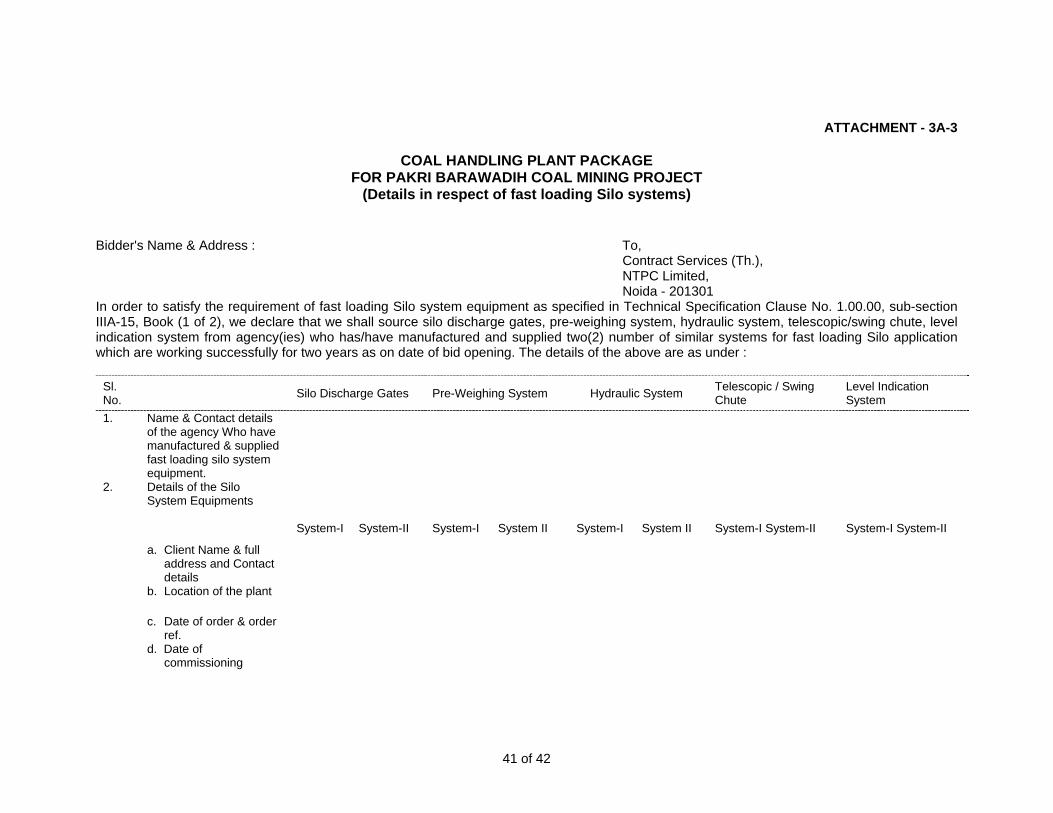
ATTACHMENT - 3A-3
COAL HANDLING PLANT PACKAGE FOR PAKRI BARAWADIH COAL MINING PROJECT
(Details in respect of fast loading Silo systems)
Bidder's Name & Address : To, Contract Services (Th.), NTPC Limited, Noida - 201301 In order to satisfy the requirement of fast loading Silo system equipment as specified in Technical Specification Clause No. 1.00.00, sub-section IIIA-15, Book (1 of 2), we declare that we shall source silo discharge gates, pre-weighing system, hydraulic system, telescopic/swing chute, level indication system from agency(ies) who has/have manufactured and supplied two(2) number of similar systems for fast loading Silo application which are working successfully for two years as on date of bid opening. The details of the above are as under :
Sl. No.
Telescopic / Swing Chute
Level Indication Silo Discharge Gates Pre-Weighing System Hydraulic System System 1. Name & Contact details
of the agency Who have manufactured & supplied fast loading silo system equipment.
2. Details of the Silo System Equipments
System-I System-II System-I System II System-I System II System-I System-II System-I System-II
a. Client Name & full address and Contact details
b. Location of the plant
c. Date of order & order ref.
d. Date of commissioning
41 of 42
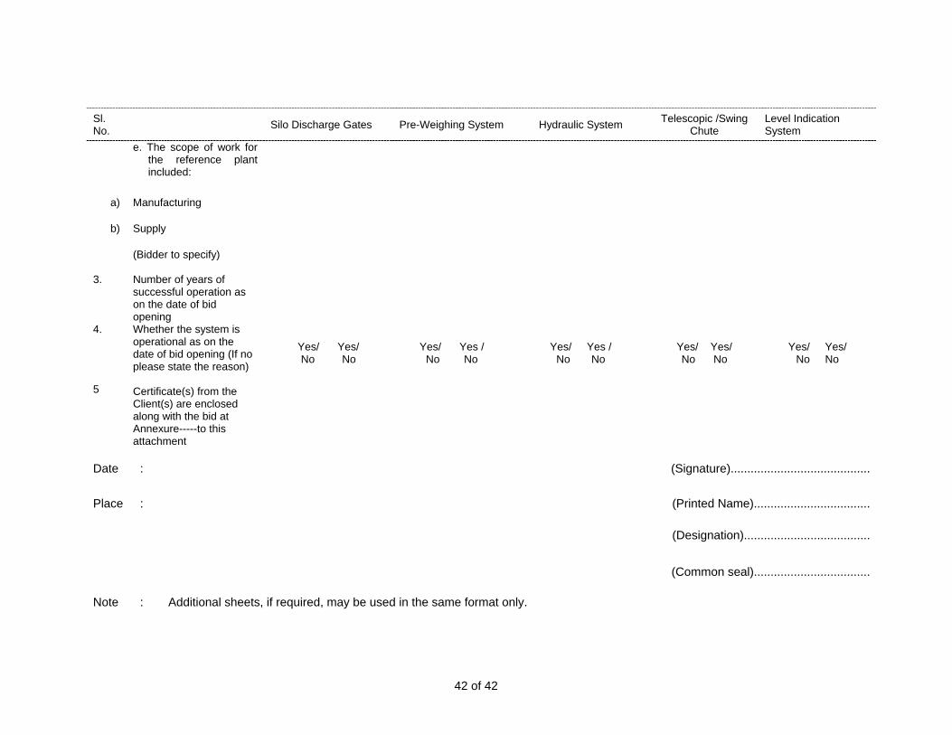
Sl. No.
Telescopic /Swing Chute
Level Indication System Silo Discharge Gates Pre-Weighing System Hydraulic System
e. The scope of work for
the reference plant included:
a) Manufacturing
b) Supply
(Bidder to specify) 3. Number of years of
successful operation as on the date of bid opening
4. Whether the system is operational as on the date of bid opening (If no please state the reason)
Yes/ Yes/ Yes/ Yes / Yes/ Yes / Yes/ Yes/ Yes/ Yes/ No No No No No No No No No No
5 Certificate(s) from the Client(s) are enclosed along with the bid at Annexure-----to this attachment
Date : (Signature)..........................................
Place : (Printed Name)...................................
(Designation)......................................
(Common seal)...................................
Note : Additional sheets, if required, may be used in the same format only.
42 of 42


COLOURCRT LVS-1 LVS-1
COLOURCRT
HMI-1 COLOURCRT
COLOURCRT
OPERATING &PROGRAMMINGPC BASED WORKSTATION # 1
PRINTER-1(132 COL.DOT MATRIX)
OPERATING &PROGRAMMINGPC BASED WORKSTATION # 2
PRINTER-2(LASER COLOR)
PRINTER-1(LASERCOLOR)
OPERATING &PROGRAMMINGPC BASED WORKSTATION # 1
OPERATING &PROGRAMMINGPC BASED WORKSTATION # 2
PLC PROCESSOR-2@
PLC PROCESSOR-1@
DUAL I/O COMMUNICATION LINK
REMOTEI/O RACK # 1
REMOTEI/O RACK # n
SWGR/CONTROL/MCC ROOM # 1
SWGR/CONTROL/MCC ROOM # n
CHP. MAIN CONTROL ROOM 6.6 KV SWGR ROOM-1(NEAR TP-4)
6.6 KV SWGR ROOM-2(NEAR TP-7)
SILO CONTROL ROOM
KBDKBDKBDKBDKBD
NOTES:1. PLC PROCESSORS –1&2 MARKED (@) SHALL CONFIGURED AS
HOT STANDBY TO EACH OTHER.2. NUMBERS AND LOCATIONS OF REMOTE I/O RACKS SHALL BE
DECIDED DURING DETAILED ENGINEERING. HOWEVER 1 NO. OFREMOTE I/O ARE TO BE PROVIDED IN EACH MCC ROOM.
FOR TENDER PURPOSE ONLY
NTPC Limited(A Govt. of India Enterprise)
PAKRI-BARWADIH COAL MINING PROJECT
PLC CONFIGURATION
PROJECT
TITLE
SIZE SCALE DRAWING NO. 7010-155-PVEB-002 SH. 1 OF 2
REV. NO.A
PAKRI-BARWADIH-PLC.DWG
PRINTER-1(LASER COLOR)
HMI-2
PRINTER-2(LASERCOLOR)
KBD
DUAL DATA COMMUNICATION LINK
REDUNDANT HMI SERVERS CLIENT CLIENT CLIENT

NOTES:• IN BOOST CHARGING MODE THE CHARGER SHALL BE
DISCONNECTED FROM LOADS.• SUITABLE INTERLOCK SYSTEM SHALL BE PROVIDED IN
BOOST CHARGING SELECTOR SWITCH TO ENSURE THE BOOST CHARGING CHARGER SHALL BE ISOLATED FROM LOAD BEFORE BOOST CHARGING.
• INTERLOCK SHALLALSO BE MADE TO ENSURE THAT THE TIE (S-3) IS CLOSED BEFORE BATTERY & CHARGER ARE ISOLATED FROM LOAD OUTPUT ISOLATOR (S-2) IS OPEN.
• BIDDER TO PROVIDE ABOVE SYSTEM FOR EACH PLC SYSTEMS FOR OFF SITE PLANTS.
LEGEND:
ISOLATOR
MCBFUSE
240V FLOAT CUM BOOST CHARGER-2 WITH CURRE NT LIMITING DEVICE AT OUTPUT
3ø, 415V AC TO 1ø, 240V AC STEP DOWN TRANSFORMER
3ø, 415V AC TO 1ø, 240V AC STEP DOWN TRANSFORMER
415 AC 50 HZ3 PHASE SUPPLY-1(3 WIRE)
TO MINI UPS24V BATTERY-1
FUSE WITHSTRIKER PIN
+ VE- VE 24V CHARGER BUS-1
+ VE- VE
DCDB-1
TO LOAD (TYP)MAIN
S3
TIE BKRNORMALLY OPEN
240V FLOAT CUM BOOST CHARGER-1 WITH CURRE NT LIMITING DEVICE AT OUTPUT
415 AC 50 HZ3 PHASE SUPPLY-1(3 WIRE)
TO MINI UPS
24V BATTERY-2
FUSE WITHSTRIKER PIN
+ VE
- VE24V CHARGER BUS-2
DCDB-2
TO LOAD (TYP)STANDARD
+ VE- VE
NTPC Limited
PAKRI BARWADIH COAL MINING PROJEC
SINGLE LINE DIAGRAM24 DC SYSTEM
DRAWING NO:7010-155-PVEB-002
SH2 OF 2
ACDC
ACDC
S2
NC
NCS2
NC
NC