raspberry pi networking cookbook - second edition - sample chapter
DESCRIPTION
Chapter No. 6 IoT – Internet of ThingsConnect your Raspberry Pi to the world with this essential collection of recipes for basic administration and common network servicesFor more information: http://bit.ly/1Zz5eQYTRANSCRIPT

Raspberry Pi Networking CookbookSecond Edition
Rick Golden
Raspberry Pi Networking Cookbook Second Edition
What this book will do for you...
Install, update, and upgrade your Raspberry PI
Confi gure a fi rewall to protect your Raspberry Pi and other devices on your local area network
Set up fi le sharing, remote access, a web server, and your own wiki
Create a wireless access point and use it as an Internet gateway
Stream video, audio, and local device data to IoT services as well as your own websites
Control devices connected to the Raspberry Pi from your phone via the web
Discover all the recipes updated for Raspbian Jessie
$ 44.99 US£ 28.99 UK
Prices do not include local sales tax or VAT where applicable
Inside the Cookbook... A straightforward and easy-to-follow format
A selection of the most important tasks and problems
Carefully organized instructions to solve problems effi ciently
Clear explanations of what you did
Solutions that can be applied to solve real-world problems
Quick answers to common problems
With increasing interest in Maker projects and the Internet of Things (IoT), students, scientists, and hobbyists are using the Raspberry Pi as a reliable, inexpensive platform to connect local devices to Internet services.
This book begins with recipes that are essential to installing the Raspberry Pi and confi guring it for network access. Then it continues with recipes for installing common networking services, such as fi rewalls and fi le sharing.
The fi nal chapters include recipes for network monitoring, streaming data from the Raspberry Pi to IoT services, and using clusters of Raspberry Pis to store and analyze large volumes of data.
Rick G
oldenR
aspberry Pi Netw
orking Cookbook
Second Edition
Connect your Raspberry Pi to the world with this essential collection of recipes for basic administration and common network services
P U B L I S H I N GP U B L I S H I N G
community experience dist i l ledP
UB
LIS
HIN
GP
UB
LIS
HIN
G
Visit www.PacktPub.com for books, eBooks, code, downloads, and PacktLib.
Free Sample

In this package, you will find: The author biography
A preview chapter from the book, Chapter 6 ' IoT – Internet of Things'
A synopsis of the book’s content
More information on Raspberry Pi Networking Cookbook Second Edition

About the Author
Rick Golden, in the summer of 1972, sat in the computer lab at SUNY Fredonia and completed his fi rst CAI tutorial on programming in APL. He was 9 years old then.
He has been programming computers for over 40 years. He has designed and developed a multitude of projects, from low-level graphics and database drivers to large-volume e-commerce platforms.
At work, Rick is currently focused on developing software to improve healthcare by mining petabytes of healthcare claims to fi nd opportunities to improve healthcare coordination. After work, Rick teaches 10-14 year olds how to program using Raspberry Pi computers.

PrefaceA Raspberry Pi 2, with its 900MHz quad-core processor, has more processing power than a network server from the late-1990s. Created as an educational tool to inspire the next generation of programmers, the Raspberry Pi is also an excellent network server. It can be used to share fi les, host websites, create Internet access points, and analyze network traffi c. Multiple Raspberry Pis can be clustered to create a single, highly available, and fault-tolerant super computer. This book shows you how.
The Raspberry Pi Foundation recognized that computers had become so expensive and arcane that programming experimentation on them had to be forbidden by parents. The parental restrictions on using computers had created a year-on-year decline in the numbers and skills levels of the A Level students applying to read Computer Science. So, the Foundation set out to create a computer that was "affordable, and powerful enough to provide excellent multimedia, a feature we felt would make the board desirable to kids who wouldn't initially be interested in a purely programming-oriented device".
2 million Raspberry Pis were sold in the fi rst two years of its release, which was not limited to educators and school children. Hobbyists were also excited to use the inexpensive Linux-based computer in their projects. In February 2015, the quad-core Raspberry Pi 2 was released with signifi cantly more power and memory than the original, which was more than enough memory and power for many typical server applications.
In this cookbook, you'll fi nd a collection of server-side recipes for the Raspberry Pi, including recipes to set up fi le servers and web servers, create secure wireless access points, and analyze network traffi c. There is even a recipe to create a highly available fault-tolerant supercomputer.

Preface
What this book covers
Chapter 1, Installation and Setup, has a number of beginner recipes to set up the Raspberry Pi as a network server, which include instructions on how to download and install new operating system images, boot for the fi rst time, and the proper way to shut down the system.
Chapter 2, Administration, has more beginner recipes to confi gure the Raspberry Pi as a network server, which includes instructions on how to execute privileged commands, confi gure remote access, and manage user accounts.
Chapter 3, Maintenance, has intermediate and advanced recipes to maintain the Raspberry Pi server. You'll learn how to update software, read the built-in documentation, and upgrade the system.
Chapter 4, File Sharing, has a number of different intermediate recipes to share fi les.
Chapter 5, Advanced Networking, has a collection of advanced recipes to set up and monitor network applications, including a fi rewall, web server, wireless access point, and network protocol analyzer.
Chapter 6, IoT - The Internet of Things, has several intermediate recipes to connect your Raspberry Pi to the Internet of Things.
Chapter 7, Clustering, has advanced recipes to create a highly available fault-tolerant supercomputer from a cluster of Raspberry Pis.

221
6IoT – Internet of Things
In this chapter, we will cover:
Easy access to hardware
Installing the GrovePi
Controlling devices from a web page
Connecting to an IoT platform
Creating an IoT gateway
IntroductionThe recipes in this chapter show how devices and sensors – things – attached to the Raspberry Pi can be connected to the Internet of Things (IoT).
The (IoT) describes the Internet when it is being used to enable physical objects – Things – to exchange data. When connected to the Internet, the Raspberry Pi can participate in the IoT, exchanging real-time data using its general-purpose input/output (GPIO) and other hardware interfaces. This chapter has a collection of recipes that show how the Raspberry Pi can participate in the Internet of Things.
The recipes in this chapter are specifi c to the Raspberry Pi. They utilize the hardware interfaces of the Raspberry Pi – the GPIO pins. The concepts can be used with other Linux computers; however, the instructions are specifi c to the Raspberry Pi.
After completing the recipes in this chapter, you will have confi gured and controlled devices and sensors attached directly to the Raspberry Pi and via the GrovePi hardware system. You will also have controlled devices attached to the Raspberry Pi from a web page hosted on the Raspberry and through the IoT service providers SmartLiving.io and ThingBox.io.

IoT – Internet of Things
222
Easy access to hardwareThis recipe demonstrates how simple it is to access hardware from a Raspberry Pi.
In this recipe, an LED connected to one of the Raspberry Pi's GPIO pins is made to blink using simple Bash commands (ls, cat, and echo).
After completing this recipe, you will be able to control the GPIO ports attached to your Raspberry Pi from the Bash command line.
Getting readyIngredients:
An Initial Setup or Basic Networking setup for the Raspberry Pi that is not powered on
An LED
A pushbutton switch
Three 330 Ohm resisters
A breadboard
A few breadboarding wires
This recipe does not require the desktop GUI and could either be run from the text-based console or from within an LXTerminal.
If the Raspberry Pi's Secure Shell server is running, this recipe can be completed remotely using a Secure Shell client.
How to do it...The steps to easily accessing hardware from the command line are:
1. Before powering on the Raspberry Pi, use the following two diagrams to connect apushbutton switch to GPIO port 23 (pin 16) and an LED to GPIO port 24 (pin 18).

Chapter 6
223
The following diagram shows the component layout for this recipe:
2. The pushbutton switch should be connected to pin 2 (5V) on one side. The other side of the pushbutton switch should have two 330 Ohm resisters connected – one resister leading to pin 6 (GND) and one resistor leading to pin 16 (GPIO 23).
3. The LED should be connected to pin 18 (GPIO port 24) on one side. The other side of the LED should have a 330 Ohm resistor connected leading to pin 20 (GND).
Turn the LED around if the first try does not work.
An LED is a light emitting diode. Diodes only allow current to flow in one direction. A reversed diode is a common electronic circuit bug.

IoT – Internet of Things
224
4. After you have validated that the pushbutton switch, the LED, and the two 330 Ohm resistors are connected correctly, power on the Raspberry Pi.
The following diagram shows the pin layout of the Raspberry Pi's GPIO interface:
5. Log in to the Raspberry Pi either directly or remotely.
6. Use the cd command to navigate through the Raspberry Pi's kernel parameters to the /sys/class/gpio directory.pi@raspberrypi ~ $ cd /sys/class/gpiocd /sys/class/gpio
pi@raspberrypi ~ $
7. Use the ls command to list the contents of the kernel parameter directory containing GPIO parameters and interfaces.pi@raspberrypi /sys/class/gpio $ lsls
export gpiochip0 unexport
pi@raspberrypi /sys/class/gpio $

Chapter 6
225
8. Use the echo command to tell the Raspberry Pi's kernel to export the interfaces to GPIO ports 23 and 24 into user space.pi@raspberrypi /sys/class/gpio $ echo 23 >exportecho 23 >export
pi@raspberrypi /sys/class/gpio $ echo 24 >exportecho 24 >export
pi@raspberrypi /sys/class/gpio $
9. Use the ls command to once again display the contents of the kernel parameters and interfaces directory, /sys/class/gpio. pi@raspberrypi /sys/class/gpio $ lsls
export gpio23 gpio24 gpiochip0 unexport
pi@raspberrypi /sys/class/gpio $
10. Notice the two new user space accessible kernel interfaces to GPIO port 23 (gpio23) and GPIO port 24 (gpio24).
11. Use the echo command to confi gure GPIO port 23 (gpio23) to receive input signals (in) and GPIO port 24 (gpio24) to send output signals (out).pi@raspberrypi /sys/class/gpio $ echo in >gpio23/directionecho in >gpio23/direction
pi@raspberrypi /sys/class/gpio $ echo out >gpio24/directionecho out >gpio24/direction
pi@raspberrypi /sys/class/gpio $
12. Use the cat command to see the current state of the pushbutton switch when it's not being pressed (0) and when it is pressed (1).pi@raspberrypi /sys/class/gpio $ cat gpio23/valuecat gpio23/value
0
pi@raspberrypi /sys/class/gpio $ # WHILE PRESSING THE BUTTON...
pi@raspberrypi /sys/class/gpio $ cat gpio23/valuecat gpio23/value
1
pi@raspberrypi /sys/class/gpio $
13. The pushbutton switch works!

IoT – Internet of Things
226
14. Use the echo command to turn the LED on (1) and then off (0).pi@raspberrypi /sys/class/gpio $ echo 1 >gpio24/valueecho 1 >gpio24/value
pi@raspberrypi /sys/class/gpio $ echo 0 >gpio24/valueecho 0 >gpio24/value
pi@raspberrypi /sys/class/gpio $
15. The LED works!
16. Use the following while loop to control the LED with the pushbutton. Use Ctrl-C (^C) to stop the while loop.pi@raspberrypi /sys/class/gpio $ in=gpio23/valuein=gpio23/value
pi@raspberrypi /sys/class/gpio $ out=gpio24/valueout=gpio24/value
pi@raspberrypi /sys/class/gpio $ while true; do echo $(cat $in) >$out; while true; do echo $(cat $in) >$out; donedone
^C^C
pi@raspberrypi /sys/class/gpio $
17. The pushbutton switch controls the LED!
18. Use the echo command to unexport GPIO ports 23 and 24 from user space, and use the ls command to see that the Raspberry Pi kernel has removed the gpio23 and gpio24 interfaces.pi@raspberrypi /sys/class/gpio $ lsls
export gpio23 gpio24 gpiochip0 unexport
pi@raspberrypi /sys/class/gpio $ echo 23 >unexportecho 23 >unexport
pi@raspberrypi /sys/class/gpio $ echo 24 >unexportecho 24 >unexport
pi@raspberrypi /sys/class/gpio $ lsls
export gpiochip0 unexport

Chapter 6
227
How it works...This recipe uses a connected input device (pushbutton switch) to activate an output device (LED). The recipe begins by connecting the input and output devices to the Raspberry Pi. Once the devices are connected, each of the devices is tested individually. Finally, a Bash script activates the output device whenever the input device signals.
Before the Raspberry Pi is powered on two devices, a pushbutton switch and an LED, are connected to the Raspberry Pi.
Connect the pushbutton switch to GPIO port 23The pushbutton switch acts as an input device. It is connected to +5v on one side via pin 2 and to GPIO port 23 on the other side via pin 16. When the pushbutton switch is pressed, GPIO port 23 (pin 16) detects a high signal coming from +5v (pin 2) through the closed pushbutton switch.
In addition to the pushbutton switch, two 330 Ohm resistors are necessary to safely complete this part of the circuit. One 330 Ohm resistor is used to limit the current fl ow when the pushbutton switch is pressed (closed) and the signal is high. The other 330 Ohm resistor is used to pull the signal down to low when the pushbutton switch is not pressed (open).
The current-limiting resistor connects the pushbutton switch to GPIO port 23 (pin 16). The pull-down resistor connects GPIO port 23 (pin 16) to GND (pin 6).
When the pushbutton switch is open, GPIO port 23 (pin 16) detects a low signal coming through the pull-down resistor connected to GND (pin 6). When the pushbutton switch is closed, GPIO port 23 (pin 16) detects a high signal coming from +5v (pin 2) through the current-limiting resistor.
Connect the LED to GPIO port 24The LED acts as an output device. It is connected to GPIO port 24 (pin 18) on one side. On the other side, the LED is connected to a current-limiting 330 Ohm resistor leading to GND (pin 20).
When GPIO port 24 (pin 18) emits a high signal, enough current passes through the circuit to light the LED. When the signal is low, the LED remains unlit.
Power on and log inOnce you have validated that the LED, the pushbutton switch, and the three protective 330 Ohm resistors are connected correctly, turn on the Raspberry Pi and log in.

IoT – Internet of Things
228
Navigating the Linux kernel with sysfsAfter you have logged in, the recipe uses the cd command to navigate to the /sys/class/gpio directory within the sysfs virtual fi le system. The sysfs virtual fi le system is a user space mapping of Linux kernel parameters and interfaces. The kernel parameters for the GPIO interface are accessible from /sys/class/gpio.
The ls command is used to see which GPIO port interfaces are currently exported from kernel space to user space. So far, no interfaces have been exported.
The gpio directory only contains three entries: two pseudo-parameters, export and unexport; and one interface, gpiochip0. The interface to gpiochip0 is not used in this recipe. The two pseudo-parameters are used to export and unexport GPIO port interfaces from kernel space to user space.
Export GPIO ports 23 and 24The recipe uses the echo command to write the numbers 23 and 24 to the export pseudo-parameter. This tells the Raspberry Pi's Linux kernel to export the interfaces to GPIO ports 23 and 24 into user space (at /sys/class/gpio).
The command line for exporting the GPIO port 23 interface, echo 23 >export, works because it writes (>) the number 23 (echo 23) to the Linux kernel pseudo-parameter /sys/class/gpio/export telling the kernel to create an interface subdirectory (gpio23) for GPIO port 23.
After the kernel has been told to export the two GPIO ports, the ls command is used once again to show that the Linux kernel has created two new GPIO port interface subdirectories, one for GPIO port 23, /sys/class/gpio/gpio23, and one for GPIO port 24, /sys/class/gpio/gpio24.
Confi gure each interface direction as input or outputThe recipe then uses the echo command to write (>) either in (for input) or out (for output) to the direction parameter within each of the GPIO ports' interface subdirectories (gpio23 and gpio24).
The input device (pushbutton switch) is connected to GPIO port 23, so the direction parameter for GPIO port 23 (gpio23) is set to input (echo in > gpio23/direction).
The output device (LED) is connected to GPIO port 24, so the direction for GPIO port 24 (gpio24) is set to output (echo out > gpio24/direction).
Once the input/output direction for each GPIO port has been confi gured, the interface to each port can be tested.

Chapter 6
229
Testing the input deviceThe input device is tested using the cat command to display the value of GPIO port 23 (gpio23/value).
The value of GPIO port 23 (gpio23/value) is displayed when the pushbutton switch is released and when it is being pressed. When the pushbutton switch is released (the switch is open), the value of GPIO port 23 (gpio23/value) is low (0). When the pushbutton switch is pressed (closed), the value is high (1).
Testing the output deviceThe output device is tested using the echo command.
When the value high is sent to GPIO port 24 (echo 1 >gpio24/value), the LED glows. When the value low is sent (echo 0 >gpio24/value), the LED stops glowing.
Using the input device to activate the output deviceAfter successfully testing the input (pushbutton switch) and output (LED) devices, the recipe connects the two devices with a simple while loop.
First, the shell variable in is defi ned to be an alias for the value of GPIO port 23 (gpio23/value) and the variable out is defi ned to be an alias for the value of GPIO port 24 (gpio24/value).
Then, the two variables are used in an infi nite loop (while true; do) that reads the input signal from GPIO port 23 ($(cat in)) and uses the echo command to write the signal to GPIO port 24 (>$out).
While the loop is running, the LED lights whenever the pushbutton switch is pressed.
Pressing Ctrl+C stops the loop.
CleanupAfter running the loop, the cat command is used to unexport the Linux kernel interfaces from user space to GPIO port 23 (/sys/class/gpio/gpio23) and GPIO port 24 (/sys/class/gpio/gpio24).
After the GPIO port interfaces have been unexported, the ls command is used to validate that the two GPIO port interfaces (gpio23 and gpio24) have been removed from the /sys/class/gpio user space directory.

IoT – Internet of Things
230
See also General-purpose input/output (https://en.wikipedia.org/wiki/General-
purpose_input/output): This Wikipedia article describes how General-purpose input/output interfaces work.
sysfs (https://en.wikipedia.org/wiki/Sysfs): This Wikipedia article describes the sysfs fi lesystem, its history, and how it works.
Pull-up resistor (https://en.wikipedia.org/wiki/Pull-up_resistor): This Wikipedia article describes how pull-up resistors are used to ensure a circuit has valid logic levels.
Diode (https://en.wikipedia.org/wiki/Diode): This Wikipedia article explains diodes in great detail.
Bash Guide for Beginners (http://tldp.org/LDP/Bash-Beginners-Guide/html/index.html): This book is a practical guide for using Bash and the Bash scripting language.
Installing the GrovePiThis recipe confi gures access to the Grove Pi extension board for the Raspberry Pi.
The Grove hardware system by Seeed is a Lego-like system for plugging together electronic components without the need for soldering.
The GrovePi by Dexter Industries turns the Raspberry Pi into a central control hub for Grove components.
The following image shows the GrovePi+ installed on a Raspberry Pi 2:

Chapter 6
231
After completing this recipe, you will be able to control Grove components attached to the GrovePi from your Raspberry Pi using the Python scripting language.
Getting readyIngredients:
An Initial Setup or Basic Networking setup for the Raspberry Pi that has been powered on, but the GrovePi has not yet been installed. You have also logged in as the user pi (see the recipes in Chapter 1, Installation and Setup for how to boot and log in, and the recipes in Chapter 2, Administration for how to log in remotely).
A GrovePi GPIO expansion board.
A Grove LED.
A Grove pushbutton switch.
Two Grove connector wires.
IoT – Internet of Things
232
If the Raspberry Pi's Secure Shell server is running, this recipe can be completed remotely using a Secure Shell client.
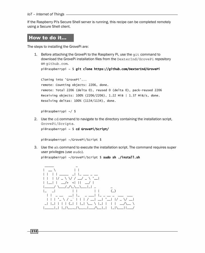
How to do it...The steps to installing the GrovePi are:
1. Before attaching the GrovePi to the Raspberry Pi, use the git command to download the GrovePi installation fi les from the DexterInd/GrovePi repository on github.com. pi@raspberrypi ~ $ git clone https://github.com/DexterInd/GrovePigit clone https://github.com/DexterInd/GrovePi
Cloning into 'GrovePi'...
remote: Counting objects: 2206, done.
remote: Total 2206 (delta 0), reused 0 (delta 0), pack-reused 2206
Receiving objects: 100% (2206/2206), 1.22 MiB | 1.37 MiB/s, done.
Resolving deltas: 100% (1134/1134), done.
pi@raspberrypi ~/ $
2. Use the cd command to navigate to the directory containing the installation script, GrovePi/Scripts.pi@raspberrypi ~ $ cd GrovePi/Script/cd GrovePi/Script/
pi@raspberrypi ~/GrovePi/Script $
3. Use the sh command to execute the installation script. The command requires super user privileges (use sudo).pi@raspberrypi ~/GrovePi/Script $ sudo sh ./install.shsudo sh ./install.sh
_____ _
| __ \ | |
| | | | _____ _| |_ ___ _ __
| | | |/ _ \ \/ / __/ _ \ '__|
| |__| | __/> <| || __/ |
|_____/ \___/_/\_\__\___|_| _ _
|_ _| | | | | (_)
| | _ __ __| |_ _ ___| |_ _ __ _ ___ ___
| | | '_ \ / _` | | | / __| __| '__| |/ _ \/ __|
_| |_| | | | (_| | |_| \__ \ |_| | | | __/\__ \
|_____|_| |_|\__,_|\__,_|___/\__|_| |_|\___||___/

Chapter 6
233
Welcome to GrovePi Installer.
Requirements:
1) Must be connected to the internet
2) This script must be run as root user
Steps:
1) Installs package dependencies:
- python-pip alternative Python package installer
- git fast, scalable, distributed revision control system
- libi2c-dev userspace I2C programming library development fi les
- python-serial pyserial - module encapsulating access for the serial port
- python-rpi.gpio Python GPIO module for Raspberry Pi
- i2c-tools This Python module allows SMBus access through the I2C /dev
- python-smbus Python bindings for Linux SMBus access through i2c-dev
- arduino AVR development board IDE and built-in libraries
- minicom friendly menu driven serial communication program
2) Installs wiringPi in GrovePi/Script
3) Removes I2C and SPI from modprobe blacklist /etc/modprobe.d/ raspi-blacklist.conf
4) Adds I2C-dev, i2c-bcm2708 and spi-dev to /etc/modules
5) Installs gertboard avrdude_5.10-4_armhf.deb package
6) Runs gertboard setup
- confi gures avrdude
- downloads gertboard known boards and programmers
- replaces avrsetup with gertboards version
- in /etc/inittab comments out lines containing AMA0
- in /boot/cmdline.txt removes: console=ttyAMA0,115200 kgdboc=ttyAMA0,115200 console=tty1
- in /usr/share/arduino/hardware/arduino creates backup of boards.txt
- in /usr/share/arduino/hardware/arduino creates backup of programmers.txt
Special thanks to Joe Sanford at Tufts University. This script was derived from his work. Thank you Joe!
Raspberry Pi will reboot after completion.

IoT – Internet of Things
234
4. As the installation continues, it will prompt for permission to install new software packages. Press the Enter key to accept the default answer to the prompts (Y).
5. When the installation script completes, you will be prompted to restart the Raspberry Pi. Instead, use the poweroff command to shut down the Raspberry Pi. _____ ______ _____ _______ _____ _______
| __ \| ____|/ ____|__ __|/\ | __ \__ __|
| |__) | |__ | (___ | | / \ | |__) | | |
| _ /| __| \___ \ | | / /\ \ | _ / | |
| | \ \| |____ ____) | | |/ ____ \| | \ \ | |
|_| \_\______|_____/ |_/_/ \_\_| \_\ |_|
Please restart to implement changes!
To Restart type sudo reboot
pi@raspberrypi ~ $ sudo poweroffsudo poweroff
Broadcast message from root@raspberrypi (pts/0) (Sun Sep 27 21:42:34 2015):
The system is going down for system halt NOW!
6. While the Raspberry Pi is shut down and the power has been disconnected, attach the GrovePi to the Raspberry Pi.
The following image shows how to attach the GrovePi+ to the Raspberry Pi 2:
7. After the GrovePi has been attached to the Raspberry Pi, reconnect the power and log in once the Raspberry Pi fi nishes booting.

Chapter 6
235
8. After logging in, use the i2cdetect command to validate that the GrovePi has been installed correctly. Note: if you are using an original Raspberry Pi, use the option –y 0 instead of –y 1.pi@raspberrypi ~ $ sudo i2cdetect -y 1sudo i2cdetect -y 1
0 1 2 3 4 5 6 7 8 9 a b c d e f
00: -- 04 -- -- -- -- -- -- -- -- -- -- --
10: -- -- -- -- -- -- -- -- -- -- -- -- -- -- -- --
20: -- -- -- -- -- -- -- -- -- -- -- -- -- -- -- --
30: -- -- -- -- -- -- -- -- -- -- -- -- -- -- -- --
40: -- -- -- -- -- -- -- -- -- -- -- -- -- -- -- --
50: -- -- -- -- -- -- -- -- -- -- -- -- -- -- -- --
60: -- -- -- -- -- -- -- -- -- -- -- -- -- -- -- --
70: -- -- -- -- -- -- -- --
9. Now, use the apt-get install command to install the Python setup tools (python-setuptools).pi@raspberrypi ~ $ sudo apt-get install -y python-setuptoolssudo apt-get install -y python-setuptools
Reading package lists... Done
Building dependency tree
Reading state information... Done
The following extra packages will be installed:
python-pkg-resources
Suggested packages:
python-distribute python-distribute-doc
The following NEW packages will be installed:
python-pkg-resources python-setuptools
0 upgraded, 2 newly installed, 0 to remove and 39 not upgraded.
Need to get 0 B/513 kB of archives.
After this operation, 1,308 kB of additional disk space will be used.
Selecting previously unselected package python-pkg-resources.
(Reading database ... 82496 fi les and directories currently installed.)
Unpacking python-pkg-resources (from .../python-pkg-resources_0.6.24-1_all.deb) ...
Selecting previously unselected package python-setuptools.
Unpacking python-setuptools (from .../python-setuptools_0.6.24-1_all.deb) ...
Setting up python-pkg-resources (0.6.24-1) ...
Setting up python-setuptools (0.6.24-1) ...
pi@raspberrypi ~ $
10. Use the cd command to navigate to the GrovePi Python software library (~/GrovePi/Software/Python).
pi@raspberrypi ~ $ cd GrovePi/Software/Pythoncd GrovePi/Software/Python
pi@raspberrypi ~/GrovePi/Software/Python $

IoT – Internet of Things
236
11. Use the python setup.py command to build and install the grovepi module.pi@raspberrypi ~/GrovePi/Software/Python $ python setup.py buildpython setup.py build
running build
running build_py
creating build
creating build/lib.linux-armv7l-2.7
copying grovepi.py -> build/lib.linux-armv7l-2.7
pi@raspberrypi ~/GrovePi/Software/Python $ sudo python setup.py installsudo python setup.py install
running install
Checking .pth fi le support in /usr/local/lib/python2.7/dist-packages/
/usr/bin/python -E -c pass
TEST PASSED: /usr/local/lib/python2.7/dist-packages/ appears to support .pth fi les
running bdist_egg
running egg_info
creating grovepi.egg-info
writing grovepi.egg-info/PKG-INFO
writing top-level names to grovepi.egg-info/top_level.txt
writing dependency_links to grovepi.egg-info/dependency_links.txt
writing manifest fi le 'grovepi.egg-info/SOURCES.txt'
reading manifest fi le 'grovepi.egg-info/SOURCES.txt'
writing manifest fi le 'grovepi.egg-info/SOURCES.txt'
installing library code to build/bdist.linux-armv7l/egg
running install_lib
running build_py
creating build/bdist.linux-armv7l
creating build/bdist.linux-armv7l/egg
copying build/lib.linux-armv7l-2.7/grovepi.py -> build/bdist.linux-armv7l/egg
byte-compiling build/bdist.linux-armv7l/egg/grovepi.py to grovepi.pyc
creating build/bdist.linux-armv7l/egg/EGG-INFO
copying grovepi.egg-info/PKG-INFO -> build/bdist.linux-armv7l/egg/EGG-INFO
copying grovepi.egg-info/SOURCES.txt -> build/bdist.linux-armv7l/egg/EGG-INFO
copying grovepi.egg-info/dependency_links.txt -> build/bdist.linux-armv7l/egg/EGG-INFO
copying grovepi.egg-info/top_level.txt -> build/bdist.linux-armv7l/egg/EGG-INFO
zip_safe fl ag not set; analyzing archive contents...
creating dist
creating 'dist/grovepi-0.0.0-py2.7.egg' and adding 'build/bdist.linux-armv7l/egg' to it
removing 'build/bdist.linux-armv7l/egg' (and everything under it)
Processing grovepi-0.0.0-py2.7.egg
creating /usr/local/lib/python2.7/dist-packages/grovepi-0.0.0-py2.7.egg
Extracting grovepi-0.0.0-py2.7.egg to /usr/local/lib/python2.7/dist-packages

Chapter 6
237
Adding grovepi 0.0.0 to easy-install.pth fi le
Installed /usr/local/lib/python2.7/dist-packages/grovepi-0.0.0-py2.7.egg
Processing dependencies for grovepi==0.0.0
Finished processing dependencies for grovepi==0.0.0
pi@raspberrypi ~/GrovePi/Software/Python $
12. Attach a Grove LED device to port D2 and a Grove pushbutton switch to port D4 of the GrovePi.
13. A Grove pushbutton switch and a Grove LED are attached to the GrovePi+, as depicted in the following image:
14. Now, use the following Python script (button.py), to test the Grove pushbutton switch. Run the test script (button.py) twice – once without pressing the pushbutton switch (0) and once while pressing the pushbutton switch (1). Notice the different results.pi@raspberrypi:~$ cat <<EOD >button.pycat <<EOD >button.py
from grovepi import *from grovepi import *
button = 4button = 4
pinMode( button, "input" )pinMode( button, "input" )
print digitalRead( button )print digitalRead( button )
EODEOD
pi@raspberrypi:~$ # without pressing the pushbutton switch
pi@raspberrypi:~$ python button.pypython button.py

IoT – Internet of Things
238
0
pi@raspberrypi:~$ # while pressing the pushbutton switch
pi@raspberrypi:~$ python button.pypython button.py
1
pi@raspberrypi:~$
15. Next, use the following Python script (led.py) to test the LED. When the script (led.py) is run, the LED should glow for one second.pi@raspberrypi:~$ cat <<EOD >led.pycat <<EOD >led.py
from grovepi import *from grovepi import *
from time import sleepfrom time import sleep
led = 2led = 2
pinMode( led, "output" )pinMode( led, "output" )
digitalWrite( led, 1 )digitalWrite( led, 1 )
sleep( 1 )sleep( 1 )
digitalWrite( led, 0 )digitalWrite( led, 0 )
EODEOD
pi@raspberrypi:~$ python led.pypython led.py
pi@raspberrypi:~$
16. Finally, use the following Python script to light the LED whenever the Grove pushbutton switch is pressed. Press Ctrl+C to stop the script.
pi@raspberrypi:~$ cat <<EOD >loop.pycat <<EOD >loop.py
from grovepi import *from grovepi import *
from time import sleepfrom time import sleep
led = 2led = 2
pinMode( led, "output" )pinMode( led, "output" )
button = 4button = 4
pinMode( button, "input" )pinMode( button, "input" )
while True:while True:
try: try:
state = digitalRead( button ) state = digitalRead( button )
digitalWrite( led, state ) digitalWrite( led, state )
sleep( 0.01 ) sleep( 0.01 )
except KeyboardInterrupt: except KeyboardInterrupt:
digitalWrite( led, 0 ) digitalWrite( led, 0 )
break break
except IOError: except IOError:
print "IOError" print "IOError"
EODEOD
pi@raspberrypi:~$ python loop.pypython loop.py
^C^C

Chapter 6
239
How it works...This recipe uses the GrovePi attached to the Raspberry Pi to activate an output device (Grove LED) when the state of an attached input device (Grove pushbutton switch) changes. The recipe begins by connecting the GrovePi and the input and output devices to the Raspberry Pi. Once the devices are connected, each of the devices is tested individually. Finally, a Python script is used to activate the output device whenever the input device changes state.
Before the GrovePi is attached to the Raspberry Pi, the GrovePi drivers are installed.
Installing the GrovePi drivers and interfacesThe GrovePi drivers and interfaces are downloaded directly from their source repository on GitHub (https://github.com/). The git clone command uses a secure Internet connection (https://) to download the GrovePi interfaces and drivers from their repository, DexterInd/GrovePi. The downloaded fi les include the installation scripts.
The installation script, install.sh, is located in the GrovePi/Scripts directory. The cd command is used to navigate to the GrovePi/Scipts directory.
In the GrovePi/Scipts directory, the sh command is used to run the install.sh script. The script requires super user privileges, so sudo is used as a command prefi x.
Before starting the installation, the install.sh script displays a complete list of the changes it will make to your Raspberry Pi. The installation script prompts you to continue with the install. Press the Enter key to accept the defaults to all questions during the installation process.
After the GrovePi interfaces and drivers are installed, you are prompted to restart the Raspberry Pi. Shut down the Raspberry Pi instead, so that you can remove the power from the Raspberry Pi and attach the GrovePi to it.
Attach the GrovePi to the Raspberry PiFollow the manufacturer's instructions on http://www.dexterindustries.com/grovepi/ to attach the GrovePi to the Raspberry Pi.
If you are attaching the original 26 pin GrovePi to one of the 40 pin models of the Raspberry Pi, make sure that pin 1 is lined up correctly. Even though the GrovePi does not cover all of the pins, it will still work perfectly.
You may need to put a protective layer between the GrovePi and the Raspberry Pi to prevent the bottom of the GrovePi from touching the Raspberry Pi's USB connectors. A snippet of the electrostatic bag in which the GrovePi was shipped is a perfect protective layer.

IoT – Internet of Things
240
Power on and log inOnce you have validated that the GrovePi is attached to the Raspberry Pi correctly, attach the power cable to the Raspberry Pi and log in after it reboots.
The i2cdetect command is used to validate that the GrovePi has been connected correctly. The –y option is used to bypass interactive mode. Only the original Raspberry Pi uses bus 0, whereas all of the newer Raspberry Pis use bus 1.
If the GrovePi is connected correctly, its chip ID 04 will be displayed at address 00 4.
Now that the GrovePi has been attached and detected, it is time to install the GrovePi's Python language Application Programming Interface (API).
Install the Python APIBefore the GrovePi API can be installed, the Python setup tools need to be installed. The apt-get install command is used to install the python-setuptools software package. After Python's setup tools are installed, the GrovePi API can be installed.
The sources for the GrovePi API are located in the GrovePi/Software/Python directory. The cd command is used to navigate to that directory.
The python command is used to run the setup.py script, fi rst to build the API and then to install the API. Installation requires super user privileges, so sudo command is used as a command prefi x during install.
Once the GrovePi Python API is installed, the hardware devices can be tested.
Test the Grove pushbutton switchThe cat command is used to create a new script, button.py, which tests the state of the Grove pushbutton switch. The lines immediately following the cat command up to the end of the data marker (<<EOD) are copied to the new script (>button.py).
The python command is used to run the button.py test script twice.
The fi rst time the button.py script is run, it is run without pressing the pushbutton switch. The result is 0 because the switch is open (not pressed).
The second time the script is run, it is run while pressing the pushbutton switch. The result is 1 because the switch is closed (pressed).
Test the Grove LEDThe cat command is also used to create another test script, led.py, which tests the Grove LED. The lines immediately following the cat command up to the end of data marker (<<EOD) are copied to the new script (>led.py).

Chapter 6
241
The python command is used to run the led.py test script. When the script (led.py) is run, the Grove LED should glow for one second.
Pressing the pushbutton switch lights the LEDThe cat command is used once more to create the loop.py Python script. This short program will loop forever sending signal values from the input device (pushbutton switch) to the output device (LED).
The loop.py script imports the complete (*) grovepi API. It also imports the sleep function from the time API.
A variable, led, is used to represent digital port 2, the port that connects the LED to the GrovePi. The pinMode function from the grovepi API is used to set the signal direction for the LED port to output.
Another variable, button, is used to represent digital port 4, the port that connects the pushbutton switch to the GrovePi. The pinMode function is used to set the signal direction for the button port to input.
The main body of the script is an infi nite loop (while True:) that only breaks when a KeyboardInterrupt exception occurs.
The loop fi rst uses the digitalRead function to receive the current value of the button port. The value received is stored in the variable state.
The value of the state variable is then sent to the led port using the digitalWrite function.
Before the while loop continues, the program sleeps for 0.01 seconds. This gives the Raspberry Pi a chance to do something else in between setting the state of the led port and reading the next state from the button port.
The while loop listens for two exceptions: KeyboardInterrupt and IOError. When a KeyboardInterrupt occurs, the script uses the digitalWrite function to send the LED port the signal for off (0) and the script breaks the while loop ending the program. When an IOError occurs, the message IOError is printed.
The python command is used to run the loop.py script. While the script is running, the LED glows whenever the pushbutton switch is pressed. The LED stops glowing whenever the pushbutton switch is released. Use Ctrl+C to send a KeyboardInterrupt exception and end the program.

IoT – Internet of Things
242
There's more…The GrovePi expansion board from Dexter Industries can connect the Raspberry PI to more than 100 components from the Grove hardware platform developed by Seeed Studio. The offi cial website is http://www.seeedstudio.com/depot/. These components can be manipulated with simple Python scripts as well as integrated into larger applications programmed in C, Go, or Java.
In addition to the digital ports used in this recipe, The GrovePi also has analog ports that can receive signal levels ranging from 0 to 1023 and can end signal levels from 0 to 255. The GrovePi also has 3 I2C ports and a Universal Asynchronous Receiver/Transmitter (UART) serial port that can be used to communicate with more complex devices.
Complete GrovePi documentation, including the Python API, can be found on Dexter Industries' website. More information about the Grove System can be found on Seeed Studio's wiki.
See also GrovePi: at http://www.dexterindustries.com/grovepi/. The GrovePi home
page has a complete list of compatible sensors and devices.
The Grove System: http://www.seeedstudio.com/wiki/Category:Grove. This wiki page describes the Lego-like Grove hardware system in more detail.
The Grove System – Python Library Documentation: http://www.dexterindustries.com/GrovePi/programming/python-library-documentation/. This website documents the Python programming language library for the GrovePi.
Python: https://www.python.org/. The Python website has complete reference documentation for the Python language.
GrovePi Windows IoT: LED Blink: https://www.hackster.io/9381/grove-pi-windows-iot-getting-started-94bf38. A blinking LED example for Windows 10 and the GrovePi.
Dexter Industries: https://en.wikipedia.org/wiki/Dexter_Industries. Dexter Industries is best known for their robotic sensors for the Raspberry Pi.
Seeed Studio: http://www.seeedstudio.com/depot/. Seeed is a hardware innovation platform developed in Shenzhen, China.
GitHub: http://github.com. GitHub is a collaborative repository for open source software.
i2cdetect: http://manpages.debian.org/cgi-bin/man.cgi?query=i2cdetect. The Debian man page for i2cdetect documents the command and its options.

Chapter 6
243
Controlling devices from a web pageThis recipe uses a simple Python script to show how devices attached to the Raspberry Pi can be controlled from a web page.
The web.py programming framework for Python can be used to serve web pages from scripts that are written in the Python programming language. This recipe features a Python script that serves a web page displaying the current state of a GrovePi LED and enables a button on the web page to turn a GrovePi LED on and off. It is a simple example, but is an excellent foundation for simple Internet of Things projects.
After completing this recipe, you will have installed and applied the web.py Python framework to serve a web page that can be used to turn an LED on and off.
Getting readyThe following are the ingredients for controlling devices from a web page:
An initial setup or basic networking setup for the Raspberry Pi that already has the GrovePi interfaces and drivers installed (see the previous recipe, Installing the GrovePi, for instructions). You have also logged in as the user pi (see the recipes in Chapter 1, Installation and Setup, for how to boot and log in and the recipes in Chapter 2, Administration, for how to log in remotely).
A GrovePi should already be attached to the Raspberry Pi.
A Grove LED should be attached to port D2 of the GrovePi.
This recipe does not require the desktop GUI and could either be run from the text-based console or from within an LXTerminal application.
If the Raspberry Pi's secure shell server is running, this recipe can be completed remotely using a secure shell client.
How to do it...The steps to controlling devices from a web page are:
1. Log in to the Raspberry Pi either directly or remotely.
2. Use the apt-get install command to install the web.py web framework for Python.pi@raspberrypi ~ $ apt-get install –y python-webpyapt-get install –y python-webpy
Reading package lists... Done
Building dependency tree
Reading state information... Done
IoT – Internet of Things
244
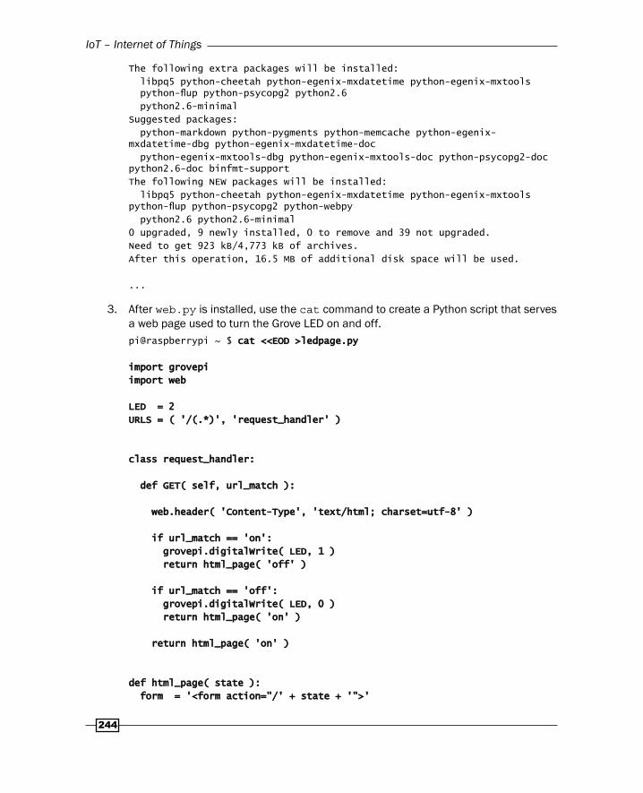
The following extra packages will be installed:
libpq5 python-cheetah python-egenix-mxdatetime python-egenix-mxtools python-fl up python-psycopg2 python2.6
python2.6-minimal
Suggested packages:
python-markdown python-pygments python-memcache python-egenix-mxdatetime-dbg python-egenix-mxdatetime-doc
python-egenix-mxtools-dbg python-egenix-mxtools-doc python-psycopg2-doc python2.6-doc binfmt-support
The following NEW packages will be installed:
libpq5 python-cheetah python-egenix-mxdatetime python-egenix-mxtools python-fl up python-psycopg2 python-webpy
python2.6 python2.6-minimal
0 upgraded, 9 newly installed, 0 to remove and 39 not upgraded.
Need to get 923 kB/4,773 kB of archives.
After this operation, 16.5 MB of additional disk space will be used.
...
3. After web.py is installed, use the cat command to create a Python script that serves a web page used to turn the Grove LED on and off.pi@raspberrypi ~ $ cat <<EOD >ledpage.pycat <<EOD >ledpage.py
import grovepiimport grovepi
import webimport web
LED = 2LED = 2
URLS = ( '/(.*)', 'request_handler' )URLS = ( '/(.*)', 'request_handler' )
class request_handler:class request_handler:
def GET( self, url_match ): def GET( self, url_match ):
web.header( 'Content-Type', 'text/html; charset=utf-8' ) web.header( 'Content-Type', 'text/html; charset=utf-8' )
if url_match == 'on': if url_match == 'on':
grovepi.digitalWrite( LED, 1 ) grovepi.digitalWrite( LED, 1 )
return html_page( 'off' ) return html_page( 'off' )
if url_match == 'off': if url_match == 'off':
grovepi.digitalWrite( LED, 0 ) grovepi.digitalWrite( LED, 0 )
return html_page( 'on' ) return html_page( 'on' )
return html_page( 'on' ) return html_page( 'on' )
def html_page( state ):def html_page( state ):
form = '<form action="/' + state + '">' form = '<form action="/' + state + '">'

Chapter 6
245
form += '<input type="submit" value="' + state + '">' form += '<input type="submit" value="' + state + '">'
form += '</form>' form += '</form>'
return '<html><body>' + form + '</body></html>' return '<html><body>' + form + '</body></html>'
if __name__ == '__main__':if __name__ == '__main__':
grovepi.pinMode( LED, 'output' ) grovepi.pinMode( LED, 'output' )
app = web.application( URLS, globals() ) app = web.application( URLS, globals() )
app.run() app.run()
EODEOD
pi@raspberrypi ~ $
4. Use the python command to start serving the web page. pi@raspberrypi ~ $ python ledpage.pypython ledpage.py
http://0.0.0.0:8080/
5. From a web browser, you will be able to see the web page. Use the IP address of your Raspberry Pi plus the port 8080 to access the web page (for example, http://192.168.2.19:8080).
6. The web page displays one button. If the LED is off, the button is labeled on. If the LED is on, the button is labeled off. Clicking the button sets the LED as stated by the button's label.
7. Use Ctrl+C to stop serving the web page.
How it works...After logging in to the Raspberry Pi, the recipe fi rst uses the apt-get install command to install the python-webpy software package. This software package contains the web.py web framework for Python.
The web.py web framework is a toolkit for creating web servers that use the Python programming language to create web pages. The Python script in this recipe also uses the GrovePi API introduced in the previous recipe, Installing the GrovePi.
Create and run the ledpage websiteThe cat command is used to create a new script, ledpage.py. The lines immediately following the cat command up to the end of the data marker (<<EOD) are copied to the new script (>ledpage.py).
This new script will serve a web page that can be used to control a GrovePi LED. In the example script, the LED is attached to port D2 of the GrovePi.

IoT – Internet of Things
246
The ledpage.py script is run using the python command. When the script is run, a web server is started listening on port 8080 of every network interface attached to the Raspberry Pi (http://0.0.0.0).
The output of the web server can be viewed in a web browser. Open a browser and browse to http://ipaddress:8080, the URL of the running ledpage.py script. Replace the ipaddress in the URL with the IP address of your Raspberry Pi (instructions for determining the IP address can be found in Chapter 2, Administration).
Action URLsThe default view (http://ipaddress:8080/) shows a single button that can be used to change the current state of the LED. The button is labeled on when the LED is off and it's labeled off when the LED is on. When clicked, the button turns the LED to the labeled state.
When the button is labeled on, clicking the button sends the browser to the URL http://ipaddress:8080/on; and when the button is labeled off, clicking the button sends the browser to the URL http://ipaddress:8080/off.
Browsing to the /on URL turns the light on and displays an off button. Browsing to the /off URL turns the light off and displays an on button. The action URLs, /on and /off, are defi ned in ledpage.py.
Use Ctrl+C to quitThe Python web server continues to run until Ctrl+C is pressed.
There's more…The ledpage.py script is a simple yet complete example of a web service that controls a device attached to the Raspberry Pi. The script can be broken into four parts: initialization, the request handler class, the html_page function, and the main loop.
InitializationThe script begins with two import statements: one for the grovepi API and one for the web API. The web API is used to set up the web server and the grovepi API is used to connect to the Grove LED.
After the import statements, two constants are defi ned: LED and URLS. The LED constant defi nes which digital output port will be used on the GrovePi (2), and the URLS constant defi nes a mapping between a regular expression (/(.*)) and a request handler (request_handler).
The defi ned regular expression (/(.*)) matches all URLs. The matched part of the URL, anything after the slash ((.*)), will be passed to the request_handler (as url_match).

Chapter 6
247
The request_handler classThe request_handler class defi nes how HTTP requests are handled by the web server. In this script, only the GET method of the HyperText Transfer Protocol (HTTP) is implemented.
When you browse to the Python web server's URL (http://ipaddress:8080), a GET method is received by the web server and the GET method (GET ( self, url_match )) of the request_handler class is called.
The GET method uses the web API function header to set the Content-type of the HTTP response to be text/html and the character set encoding to be UTF-8 (charset=utf-8). The Content-type response header tells the browser what type of web content (web page, plain text, image, audio, video, and so on) is located at this URL. The response for this URL is a web page (text/html) that uses the UTF-8 character set.
Then, the GET method checks the value of the url_match parameter.
When the url_match is on (http://ipaddress:8080/on), the grovepi API function digitalWrite is used to fi rst turn the LED on (1) and then return an html_page to the browser with an off button.
When the url_match is off (http://ipaddress:8080/off), the digitalWrite function is used to turn the LED off (0) and an html_page is returned to the browser with an on button.
If the matched URL (url_match) is neither on nor off, an html_page with an on button is returned to the browser. The state of the LED is not changed.
The html_page functionThe html_page function (html_page( state )) renders the HTML that will be sent to the browser to display the web page.
The function has one parameter, state, which is used to specify the label (value) for the button (<input type="submit">) and the action for the HTML <form> tag.
A string variable, form, is created to build the HTML <form> part of the web page.
The action attribute of the HTML <form> tag is set either to /on or /off depending on the value of the state parameter. The action attribute defi nes the URL where the browser will be sent when the HTML <form> is submitted (that is, when the button is pressed).
The value attribute (the label) of the <input type="submit"> tag (the button) is set either to on or to off depending on the value of the state parameter. When clicked, the tag (the button) will submit the HTML <form>.
Once the HTML <form> tag is completely defi ned including its end tag </form>, it is wrapped in a <body> tag and an <html> tag to complete the minimal HTML web page.

IoT – Internet of Things
248
The complete web page is returned to the request_handler, which sends the web page to the browser.
The main loopThe main loop begins if __name__ == '__main__': and is called once after the html_page function and the request_handler have been defi ned.
The main loop fi rst uses the grovepi API to initialize the LED to the output pinMode. The GrovePi digital ports can either be used to listen for signals or to trigger them. For this script, the LED port is confi gured for output.
After the LED port is confi gured, the web API's application function is used to create a web application that listens for the specifi ed URLS using Python's default global variables (globals()) as the application context.
The fi rst parameter to the web.application function, URLS, defi nes the mapping between URL request patterns (regular expressions) and their request handlers (Python classes). The second parameter defi nes the application context (in this case, it is the global context). The web.application function returns a web application object (app) that encapsulates the HTTP protocol and manages the web server.
Finally, the web server is started using the run function of the newly created web application object (app).
The web application listens by default on port 8080 of all the network interfaces attached to the Raspberry Pi (0.0.0.0). The app.run function continues until it is interrupted (by Ctrl+C).
More information on using web.py to create web applications using the Python scripting language can be found on the web.py website (http://webpy.org/).
See also web.py (http://webpy.org/): This web framework was originally developed at
reddit.com where it grew to serve millions of page views per day.
web.py – Tutorial (http://webpy.org/docs/0.3/tutorial): This is the root of the web.py tutorial.
Regular Expression HOWTO (https://docs.python.org/2/howto/regex.html): This is an introductory tutorial to using regular expressions in Python.

Chapter 6
249
Hypertext Transfer Protocol (https://en.wikipedia.org/wiki/Hypertext_Transfer_Protocol): This Wikipedia article is about the HTTP protocol.
HTML (https://en.wikipedia.org/wiki/HTML): This Wikipedia article describes the Hypertext Markup Language (HML) and its history.
Connecting to an IoT platformThis recipe connects your Raspberry Pi to the SmartLiving (http://smartliving.io) Internet of Things (IoT) platform.
The SmartLiving IoT platform uses a web browser to confi gure rules that respond to sensors and/or activate IoT devices attached to your Raspberry Pi. The SmartLiving API includes drivers for the GrovePi from Dexter Industries. This recipe integrates your Raspberry Pi with the SmartLiving platform and uses it to control a GrovePi device attached to your Raspberry Pi.
After completing this recipe, you will be able to control Grove devices attached to your Raspberry Pi using the SmartLiving Internet of Things platform.
Getting ready Ingredients:
A Basic Networking setup for the Raspberry Pi that already has the GrovePi interfaces and drivers installed (see the previous recipe, Installing the GrovePi, for instructions). You have also logged in as the user pi (see the recipes in Chapter 1, Installation and Setup for how to boot and log in and the recipes in Chapter 2, Administration for how to log in remotely).
The Raspberry Pi should be connected to the Internet.
A GrovePi should already be attached to the Raspberry Pi.
A Grove LED should be attached to port D2 of the GrovePi.
This recipe does not require the desktop GUI and could either be run from the text-based console or from within an LXTerminal.
If the Raspberry Pi's Secure Shell server is running, this recipe can be completed remotely using a Secure Shell client.

IoT – Internet of Things
250
How to do it...The steps to controlling IoT devices from the SmartLiving platform are:
1. First, create a free account and log in to the SmartLiving platform at http://beta.smnartliving.io.
2. Click on the plus icon to create a new device.

Chapter 6
251
3. Select the device type Raspberry Pi and name the device (MyGoldenPi). Click the right arrow icon to continue.

IoT – Internet of Things
252
4. Select the Raspberry Pi by clicking on the Raspberry Pi logo.
5. Select settings by clicking on the gear icon.
Chapter 6
253
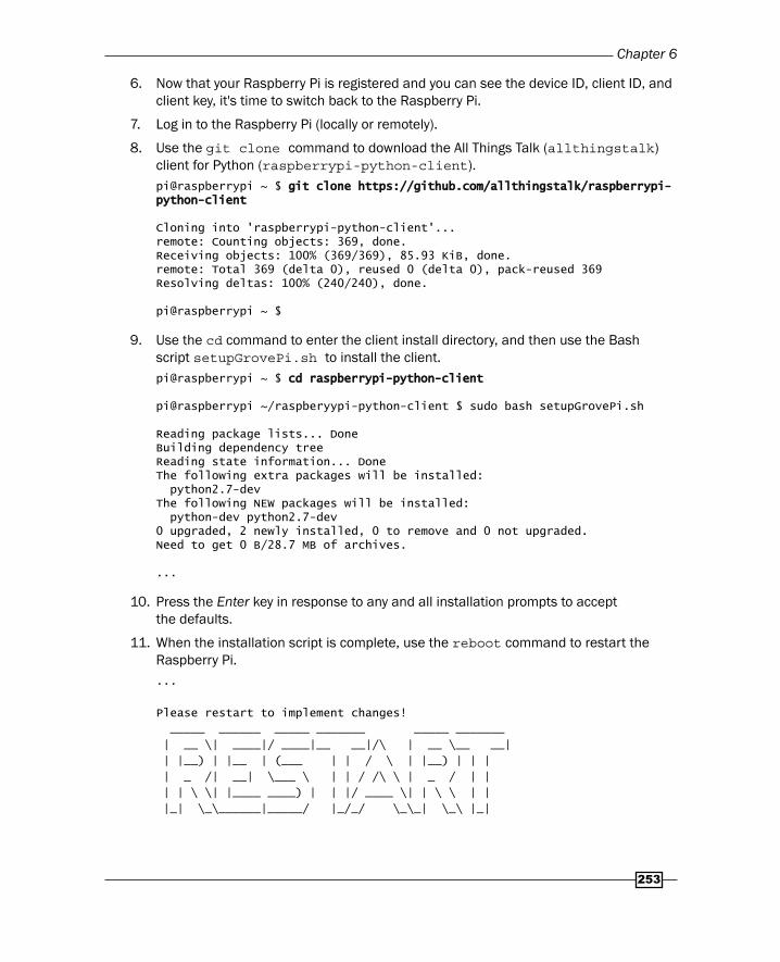
6. Now that your Raspberry Pi is registered and you can see the device ID, client ID, and client key, it's time to switch back to the Raspberry Pi.
7. Log in to the Raspberry Pi (locally or remotely).
8. Use the git clone command to download the All Things Talk (allthingstalk) client for Python (raspberrypi-python-client).pi@raspberrypi ~ $ git clone https://github.com/allthingstalk/raspberrypi-git clone https://github.com/allthingstalk/raspberrypi-python-clientpython-client
Cloning into 'raspberrypi-python-client'...remote: Counting objects: 369, done.Receiving objects: 100% (369/369), 85.93 KiB, done.remote: Total 369 (delta 0), reused 0 (delta 0), pack-reused 369Resolving deltas: 100% (240/240), done.
pi@raspberrypi ~ $
9. Use the cd command to enter the client install directory, and then use the Bash script setupGrovePi.sh to install the client. pi@raspberrypi ~ $ cd raspberrypi-python-clientcd raspberrypi-python-client
pi@raspberrypi ~/raspberyypi-python-client $ sudo bash setupGrovePi.sh
Reading package lists... DoneBuilding dependency tree Reading state information... DoneThe following extra packages will be installed: python2.7-devThe following NEW packages will be installed: python-dev python2.7-dev0 upgraded, 2 newly installed, 0 to remove and 0 not upgraded.Need to get 0 B/28.7 MB of archives.
...
10. Press the Enter key in response to any and all installation prompts to accept the defaults.
11. When the installation script is complete, use the reboot command to restart the Raspberry Pi....
Please restart to implement changes!
_____ ______ _____ _______ _____ _______
| __ \| ____|/ ____|__ __|/\ | __ \__ __|
| |__) | |__ | (___ | | / \ | |__) | | |
| _ /| __| \___ \ | | / /\ \ | _ / | |
| | \ \| |____ ____) | | |/ ____ \| | \ \ | |
|_| \_\______|_____/ |_/_/ \_\_| \_\ |_|

IoT – Internet of Things
254
Please restart to implement changes!
To Restart type sudo reboot
pi@raspberrypi ~/raspberrypi-python-client $ sudo rebootsudo reboot
Broadcast message from root@raspberrypi (pts/0) (Mon Oct 12 17:07:11 2015):
The system is going down for reboot NOW!
12. Now that the All Things Talk (Smart Living) client has been installed, it's time to test the Internet of Things.
13. Log back in to the Raspberry Pi (locally or remotely).
14. Use the cd command to change to the directory with the Smart Living Python client, raspberrypi-python-client.pi@raspberrypi ~ $ cd raspberrypi-python-clientcd raspberrypi-python-client
pi@raspberrypi ~/ raspberrypi-python-client $
15. Use the cat command to create a Python script (ledserver.py) that connects a Grove LED on port D2 to the Smart Living platform. Make sure you replace the values of the three confi guration parameters (IOT.DeviceId, IOT.ClientId, and IO.ClientKey) with the values from your Smart Living account (from step 6).pi@raspberrypi ~/ raspberrypi-python-client $ cat <<EOD >ledserver.pycat <<EOD >ledserver.py
import grovepiimport grovepi
import ATT_IOT as IOTimport ATT_IOT as IOT
import timeimport time
LED = 2LED = 2
def on_message( id, value ):def on_message( id, value ):
if id.endswith( str( LED ) ): if id.endswith( str( LED ) ):
value = value.lower() value = value.lower()
if value == "true": if value == "true":
grovepi.digitalWrite( LED, 1 ) grovepi.digitalWrite( LED, 1 )
if value == "false": if value == "false":
grovepi.digitalWrite( LED, 0 ) grovepi.digitalWrite( LED, 0 )
# ignore unkown ids and values # ignore unkown ids and values
if __name__ == '__main__':if __name__ == '__main__':

Chapter 6
255
grovepi.pinMode( LED, 'output' ) grovepi.pinMode( LED, 'output' )
IOT.DeviceId = "JKi92itLxuwZbLuuYXQug8I" IOT.DeviceId = "JKi92itLxuwZbLuuYXQug8I"
IOT.ClientId = "golden" IOT.ClientId = "golden"
IOT.ClientKey = "jlsvtobazhs" IOT.ClientKey = "jlsvtobazhs"
IOT.on_message = on_message IOT.on_message = on_message
IOT.connect() IOT.connect()
IOT.addAsset( LED, "LED", "Light Emitting Diode", True, "boolean" ) IOT.addAsset( LED, "LED", "Light Emitting Diode", True, "boolean" )
IOT.subscribe() IOT.subscribe()
while True: while True:
time.sleep( .1 ) time.sleep( .1 )
EODEOD
pi@raspberrypi ~ $
16. Use the python command to run the newly created script.pi@raspberrypi ~/ raspberrypi-python-client $ python ledserver.pypython ledserver.py
connected with http server
HTTP PUT: /asset/JKi92itLxuwZbLuuYXQug8I2
HTTP HEADER: {'Auth-ClientId': 'golden', 'Content-type': 'application/json', 'Auth-ClientKey': 'jlsvtobazhs'}
HTTP BODY:{"name":"LED","description":"Light Emitting Diode", "style": "Undefi ned","is":"actuator","profi le": {"type":"boolean" },"deviceId":"JKi92itLxuwZbLuuYXQug8I" }
(200, 'OK')
{"deviceId":"JKi92itLxuwZbLuuYXQug8I","id":"JKi92itLxuwZbLuuYXQug8I2","name":"LED","is":"actuator","description":"Light Emitting Diode","createdOn":"2015-10-13T00:36:01.742Z","createdBy":"555a3d487ae2530b385b2173","updatedOn":"2015-10-13T01:07:44.074Z","updatedBy":"555a3d487ae2530b385b2173","profi le":{"type":"boolean"},"state":null,"style":"undefi ned","control":{"name":null,"widgetUrl":null}}
Connected to mqtt broker with result code 0
subscribing to: client/golden/in/device/JKi92itLxuwZbLuuYXQug8I/asset/+/command
(0, 1)
Subscribed to topic, receiving data from the cloud: qos=(0,)

IoT – Internet of Things
256
17. In the browser, refresh the Smart Living device page. The Raspberry Pi device (MyGoldenPi) now has a new device (LED).
18. Toggle the boolean switch on the Smart Living web page and the Grove LED turns on and off while the running ledserver.py script prints additional status messages.Incoming message - topic: client/golden/in/device/JKi92itLxuwZbLuuYXQug8I/asset/JKi92itLxuwZbLuuYXQug8I2/command, payload: true
Incoming message - topic: client/golden/in/device/JKi92itLxuwZbLuuYXQug8I/asset/JKi92itLxuwZbLuuYXQug8I2/command, payload: false
19. Press Ctrl+C to stop the ledserver.py script.
How it works…This recipe has three parts: registering a Raspberry Pi device with the Smart Living IoT platform, installing the Smart Living client API, and fi nally running a script that exchanges signals between the Smart Living platform and the Raspberry Pi.

Chapter 6
257
Register your Raspberry Pi with the IoT platform The recipe begins by registering for a free account at http://beta.smartliving.io.
After registering for an account, a new Raspberry Pi device interface (MyGoldenPi) is created and the Device id, Client id, and Client key for this device are displayed. These three confi guration values are used later in this recipe to connect the Raspberry Pi to the Smart Living IoT platform.
Install the IoT platform APIThe recipe continues by logging in to the Raspberry Pi.
The git clone command is used to download the All Things Talk client API for the Raspberry Pi (allthingstalk/raspberrypi-python-client) – the Python API that is used to communicate with the Smart Living IoT platform.
After the client API is downloaded, the bash command is used to run the setGrovePi.sh script from the client API directory (raspberrypi-python-client). The setupGrovePi.sh installation script installs additional software packages and Python libraries.
Exchange signals with the IoT platformOnce the Smart Living client API is installed, the cat command is used to create a short Python script (ledserver.py) that listens for signals from the Smart Living IoT platform.
The script is run from the raspberrypi-python-client directory using the python command. While the script is running, the Raspberry Pi is connected to the Smart Living IoT platform and receives signals from the IoT platform that turn the LED on and off.
The IoT signals are sent using the Raspberry Pi device page on the Smart Living website. The device page has an actuator labeled LED. By toggling the false – true switch under the LED label, a signal is sent from Smart Living platform through the Internet of Things to the Raspberry Pi. A false signal turns the LED off. A true signal turns the LED on.
A local keyboard interrupt signal (pressing Ctrl+C on the keyboard) stops the script.
There's more…The Python script, ledserver.py, is a simple demonstration of how a Raspberry Pi can be connected to an Internet of Things platform. The script listens for and responds to a binary signal sent from the Smart Living IoT platform. The signal sent from the IoT platform controls a device attached to the Raspberry Pi (an LED).
The script has three parts: initialization, the signal handler, and the main loop.

IoT – Internet of Things
258
InitializationThe script begins with three import statements: one for the GrovePi API (grovepi), one for the All Things Talk API (ATT_IOT), and one for the time API. The time API provides the sleep function; the ATT_IOT API is used to connect with the Smart Living IoT platform, and the grovepi API is used to connect to the Grove LED.
After the import statements, a single constant is defi ned, LED, to represent the digital port that will be used on the GrovePi (2).
The signal handlerThe signal handler function on_message( ID, value ) defi nes the actions that are taken when signals (messages) are received from the IoT platform.
When the last character (endswith) of the message id is equal to the registered asset ID of the LED (str( LED )), then the message applies to the LED asset.
If the value of the message (converted to lowercase, lower) is "true", the LED will be turned on using the grovepi API (digitalWrite( LED, 1 )). When the value is "false", the LED will be turned off (digitalWrite( LED, 0 )).
The main loopThe main loop (if __name__ == '__main__':) begins by using the GrovePi API to set the pinmode of the LED to output.
The Smart Living client API (IOT) is confi gured using the DeviceId, ClientId, and ClientKey confi guration parameters. They are set to the values displayed earlier, during the Smart Living registration. The IOT signal handler parameter, on_message, is set to the signal handling function, on_message.
Now that the client API (IOT) is confi gured, the Raspberry Pi is ready to connect to the Smart Living IoT platform, register a new device asset (addAsset), and subscribe to messages coming from the IoT platform.
The IOT.connect method establishes a connection to the Smart Living IoT platform using the previously specifi ed DeviceId, ClientId, and ClientKey.
With the connection established, the Raspberry Pi lets the IoT platform know (addAsset) that there is a binary ("boolean") output (True) device attached to port D2 (LED). The output device is labeled "LED" and has a short description, "Light Emitting Diode".
The IOT.subscribe method lets the Smart Living IoT platform know that the Raspberry Pi is ready to receive signals (messages) from the platform.
The on_message function was previously defi ned as the signal handler. So, when a new signal (message) arrives for the Raspberry Pi, the on_message function receives the signal and acts upon its id and value.

Chapter 6
259
When a "true" signal is received, the LED is turned on. When a "false" signal is received, the LED is turned off.
IoT RulesAlthough this recipe does show how the Raspberry Pi can connect to and exchange signals with the Smart Living IoT platform, it does not show how to create new IoT Rules.
The Smart Living website (http://smartliving.io) has a number of examples of how IoT Rules can be used to react to and control the Raspberry Pi:
Detect movement – light an LED when a sensor detects movement
Unplugged smartphone – vibrate when a phone is removed from its charger
Smart doorbell – the doorbell rings your smartphone
Light sensor – display light levels in a remote room on your smartphone
Smart shop window – use a QR code to control the light in a window
Visit the Smart Living website for detailed instructions and a complete reference to using the Smart Living IoT platform with the Raspberry Pi and other devices.
See also SmartLiving (http://www.smartliving.io/): Use the Maker link to sign up for a
Smart Living account.
All Things Talk (http://allthingstalk.com/): The All Things Talk website has more details about the home and business versions of their Internet of Things platform.
Raspberry Pi kit (http://docs.smartliving.io/kits/linux-raspberry-pi/stepbystep/): This tutorial is a guide for connecting your Raspberry Pi to Smart Living.
Raspberry Pi kit Experiments Guide (http://docs.smartliving.io/kits/linux-raspberry-pi/experiments/): There are fi ve experiments on this website to get you started with the IoT.
Creating an IoT gatewayThis recipe turns your Raspberry Pi into an IoT gateway using The ThingBox (http://thethingbox.io/) powered by Node-RED (http://nodered.org/).
The ThingBox is a Raspbian-based operating system distribution for wiring together hardware devices, APIs, and online services in new and interesting ways. It comes preinstalled with the Node-RED visual tool for wiring the Internet of Things.
IoT – Internet of Things
260
In this recipe, The ThingBox is deployed and a new fl ow is created that lights an LED attached to the Raspberry Pi while a pushbutton is pressed. This is a very simple example, but completely demonstrates how The ThingBox is used. At the end of the recipe, there is a list of additional nodes that could be used in your next project.
After completing this recipe, your Raspberry Pi will be an IoT gateway.
Getting ready Ingredients:
An Internet connection for downloading The ThingBox distribution
An SD card – 4 GB or greater (class 10 has the best performance)
A Raspberry Pi connected to the local network
This recipe only requires the desktop GUI to set up a wireless network.
Once the Raspberry Pi is running and connected to the network, this recipe is completed from another computer using a web browser.
How to do it...The steps to creating an IoT gateway from your Raspberry Pi are:
1. Download the latest image fi le from The ThingBox website, http://thethingbox.io/#packagestable (see the recipe Downloading new SD cards in Chapter 1, Installation and Setup).
2. Write the image fi le to the SD card (see the appropriate disk utility recipe for your computer in Chapter 1, Installation and Setup).
3. Boot your Raspberry Pi using the updated SD card.
4. If your Raspberry Pi uses a Wi-Fi adapter to connect to the local network, you will need to log in to the Raspberry Pi GUI once (username: root, password: raspberry) and use the Wi-Fi confi g utility to confi gure the wireless network adapter.
Chapter 6
261
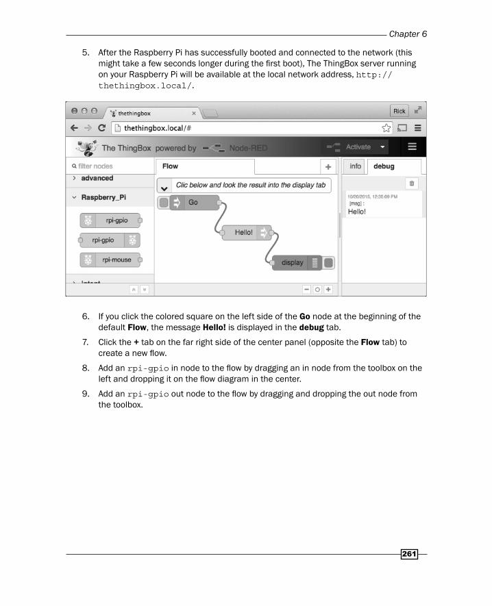
5. After the Raspberry Pi has successfully booted and connected to the network (this might take a few seconds longer during the fi rst boot), The ThingBox server running on your Raspberry Pi will be available at the local network address, http://thethingbox.local/.
6. If you click the colored square on the left side of the Go node at the beginning of the default Flow, the message Hello! is displayed in the debug tab.
7. Click the + tab on the far right side of the center panel (opposite the Flow tab) to create a new fl ow.
8. Add an rpi-gpio in node to the fl ow by dragging an in node from the toolbox on the left and dropping it on the fl ow diagram in the center.
9. Add an rpi-gpio out node to the fl ow by dragging and dropping the out node from the toolbox.
IoT – Internet of Things
262
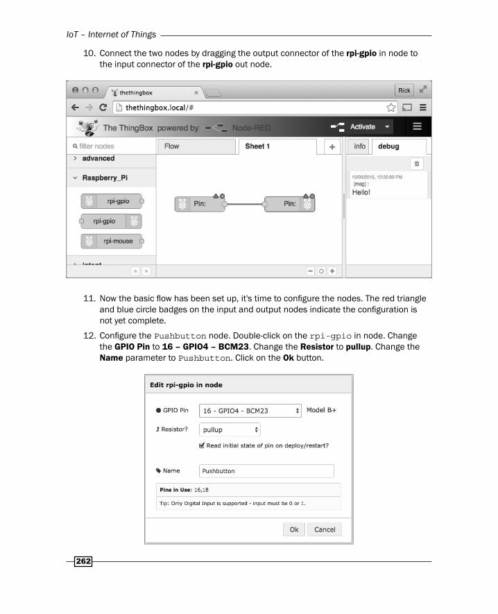
10. Connect the two nodes by dragging the output connector of the rpi-gpio in node to the input connector of the rpi-gpio out node.
11. Now the basic fl ow has been set up, it's time to confi gure the nodes. The red triangle and blue circle badges on the input and output nodes indicate the confi guration is not yet complete.
12. Confi gure the Pushbutton node. Double-click on the rpi-gpio in node. Change the GPIO Pin to 16 – GPIO4 – BCM23. Change the Resistor to pullup. Change the Name parameter to Pushbutton. Click on the Ok button.

Chapter 6
263
13. Confi gure the LED node. Double-click on the rpi-gpio out node. Change the GPIO Pin to 18 – GPIO5 – BCM24. Change the Type to Digital output. Change the Name to LED. Click on the Ok button.
14. Rename the fl ow diagram. Double-click on the name, Sheet 1. Change the Name of the fl ow diagram to Pushbutton LED. Click on the Ok button.

IoT – Internet of Things
264
15. Start the fl ow by clicking on the red Activate button. Wait until the Successfully Deployed message appears.
16. The Pushbutton LED fl ow has started!
17. Press and hold the Pushbutton. The LED glows. Release the Pushbutton and the LED stops glowing.
18. Notice that the values next to the green status indicators under the input and output nodes change from 0 to 1 whenever the pushbutton is pressed.

Chapter 6
265
19. The ThingBox IoT gateway is responding to a hardware signal by sending a hardware signal. Your IoT gateway works!
How it worksThis recipe has two main parts:
Creating the bootable SD card for The ThingBox IoT gateway
Creating the Pushbutton LED fl ow in the running IoT gateway
You may also need to confi gure your Raspberry Pi's wireless networking.
And you may want to run the example fl ow when The ThingBox is ready.
Creating the bootable SD cardThe current ThingBox bootable disk image is available from The ThingBox website (http://thethingbox.io/#packagestable). After the image is downloaded, it needs to be written to an SD card that has at least 4 GB of disk space. Class 10 SD cards have the best performance. Instructions for creating a bootable SD card can be found in Chapter 1, Installation and Setup.
Once the ThingBox image is written to the SD card, use it to boot the Raspberry Pi. The initial boot takes longer as the fi lesystem is expanded to fi ll the whole SD card. After the initial boot, subsequent boots will be much faster.
Confi guring wireless networkingIf your Raspberry Pi depends on a Wi-Fi adapter for networking, you will need to log in to the Raspberry Pi desktop after the initial boot and confi gure wireless networking. Use the username root and the default password raspberry.
The wireless networking confi guration application is available from the Raspberry Pi Menu > Preferences > WiFi Confi guration menu.
Once the WiFi Confi guration application is running, click Scan to display the available networks. Double-click on your network's SSID to enter your network's Private Security Key (PSK) and then click Add to add this device to the list of known Wi-Fi interfaces.
Close the Scan Results window and you can observe connection status changes in the WiFi Confi guration window. After adding the SSID and PSK for your network, the Raspberry Pi will continue to use that confi guration by default at each boot.
The Wi-Fi confi guration can also be set from the ThingBox user interface. Choose Settings from the confi guration menu at the top-right of the user interface (the three bars next to the Activate button).

IoT – Internet of Things
266
The ThingBox is readyAfter the Raspberry Pi boots, it broadcasts its name, thethingbox, to the local multicast DNS server. In a few seconds, after the mDNS server updates, the ThingBox user interface is accessible at the URL http://thethingbox.local/.
There is no need for additional network confi guration. However, the device name and other network parameters can be changed from the confi guration menu at the top-right of the user interface.
Running the example fl owWhen the ThingBox is fi rst accessed, it displays a default Flow made up of three nodes: Go, Hello!, and display.
Each node has confi guration parameters that are set by double-clicking on the node. Nodes can also have multiple inputs and outputs, and can process more than one message.
The default Flow is activated by clicking the colored square that is on the left side of the Go node. Clicking the square sends a message (msg) to the Hello! node.
The Hello! node receives the message (msg) and sets the payload parameter of the message to "Hello!" and then sends the message on to the display node.
The display node outputs the value of the msg.payload parameter in the debug tab of the right sidebar.
This completes the default Flow.
Go with the fl owAll fl ows follow the same basic pattern.
A message (msg) is sent from node to node along the paths that connect each node.
Each node can read and update the msg as it passes through the node adding, updating, or removing msg parameters until the msg is passed on to the next node.
After reaching the end of a fl ow, the message (msg) is discarded.
Creating the pushbutton LED fl owThe Pushbutton LED fl ow is created by clicking on the + tab at the top-right of the center panel. This creates a new fl ow sheet with the default name of Sheet 1.
From the Raspberry Pi section of the toolbox on the left, drag an rpi-gpio in node onto the blank fl ow sheet. Also drag an rpi-gpio out node onto the fl ow sheet.

Chapter 6
267
Connect the two nodes by fi rst clicking on the output connector of the rpio-gpio in node and dragging until a path forms and connects to the input connector of the rpio-cpio out node.
Now, double-click on each node and enter the appropriate confi guration information. The rpi-gpio in node is named Pushbutton, connected to GPIO4, and has a pullup Resistor. The rpi-gpio out node is named LED, has the Type Digital output, and connects to GPIO5. The fl ow sheet is renamed Pushbutton LED by double-clicking the sheet name, Sheet 1.
Once the nodes are confi gured, clicking on the red Activate button deploys the fl ow. The Activate button is red whenever there are changes to the fl ow. When the fl ow has been deployed, the button turns gray.
While the Pushbutton LED fl ow is active, the LED glows while the pushbutton is pressed and the LED stops glowing when the pushbutton is released.
Notice that the green status indicators under the two nodes also change from 0 to 1 while the pushbutton is pressed. The Node-RED platform is processing each button press.
Your Raspberry Pi is now a gateway for the Internet of Things!
There's more…This recipe is a very simple example of The ThingBox powered by Node-RED.
There is a large library of available nodesThere are dozens of additional APIs and services in the Node-RED platform.
Raspberry Pi
GPIO – the hardware GPIO pins
Mouse – pressing the mouse buttons
General I/O
HTTP – ReSTful services and web pages
MQTT – message queues
Web Sockets – JSON messages
TCP/UDP – data streams
Serial Port – character streams

IoT – Internet of Things
268
Data Parsing
CSV – comma-separated values
JSON – JavaScript object notation
XML – extensible markup language
HTML – hypertext markup language
Social
Email – send/receive e-mail messages
Twitter – send/receive tweets
Esendx – send SMS messages
Google Calendar – add, update, and react to events
RSS – monitor RSS/Atom feeds
Storage
File – read/write files on disk
Carriots – data collection from connected objects
Emoncms – process and visualize environmental data
Evrythng – drive applications with real-time data
Exosite – operationalized cloud processing
Thingspeak – open IoT platform
Tinamous – IoT platform for privacy and collaboration
Xively – enterprise IoT application platform
Wait 40 seconds before powering off or rebootingThere is one particular caution that is repeated in The ThingBox documentation. It says do not shut down or reboot the Raspberry Pi for at least 40 seconds after activating (saving) any fl ow – even if the fl ow starts working earlier than that!
Saving the updated fl ow diagram to disk is scheduled as an independent task that runs in parallel with the other tasks (nodes) that are currently running in the Node-RED server. So, it is quite likely that changes to the fl ow diagrams are activated in the Node-RED server before they are persisted to disk.

Chapter 6
269
See also The ThingBox Project (http://thethingbox.io/): Use Internet of Things
technologies without any technical knowledge and for free.
Node-RED (http://nodered.org/): Node-RED is a visual tool for wiring the Internet of Things.
Carriots (https://www.carriots.com/): Carriots is an IoT platform that will store a year of data for 10 devices for free.
Emoncms (http://emoncms.org/): Emoncms is a powerful open source web app for processing, logging, and visualizing energy, temperature, and other environmental data.
Evrythng (https://evrythng.com/): Evrythng is an IoT platform that connects any consumer product to the web and manages real-time data to drive applications.
Thingspeak (https://thingspeak.com/): Thingspeak is an open source platform for the Internet of Things.
Tinamous (https://www.tinamous.com/): Tinamous integrates status posts, alerts, and sensor measurements using simple, open connectivity solutions easily connecting people and Internet of Things devices.
Xively (https://xively.com/): Xively simplifi es the way companies securely and robustly connect their products and users, manage IoT data at scale, and engage more closely with their customers, users, and partners.
Zero-confi guration networking (https://en.wikipedia.org/wiki/Zero-configuration_networking): This Wikipedia article describes the zero-confi guration networking that The ThingBox uses to announce its location at http://thethingbox.local/.

Where to buy this book You can buy Raspberry Pi Networking Cookbook Second Edition from the
Packt Publishing website.
Alternatively, you can buy the book from Amazon, BN.com, Computer Manuals and most internet
book retailers.
Click here for ordering and shipping details.
www.PacktPub.com
Stay Connected:
Get more information Raspberry Pi Networking Cookbook Second Edition