rational design for frp strengthened concrete structures in fire · · 2017-08-05rational design...
TRANSCRIPT

Rational design for FRP strengthened reinforced concrete structures in fireRational design for FRP strengthened reinforced concrete structures in fire
Mark F. Green and Luke A. BisbyQueen’s University at Kingston University of Edinburgh
Rational Approaches for Fire Resistance Design of Concrete Structures12 April 2015, ACI Spring Convention, Kansas City
1

Outline
• FRP and High Temperature• Description of current ACI 440F recommendations• Description of proposed changes to ACI 440F• Loading during fire event• Thermal modelling• Structural modelling• Examples
2
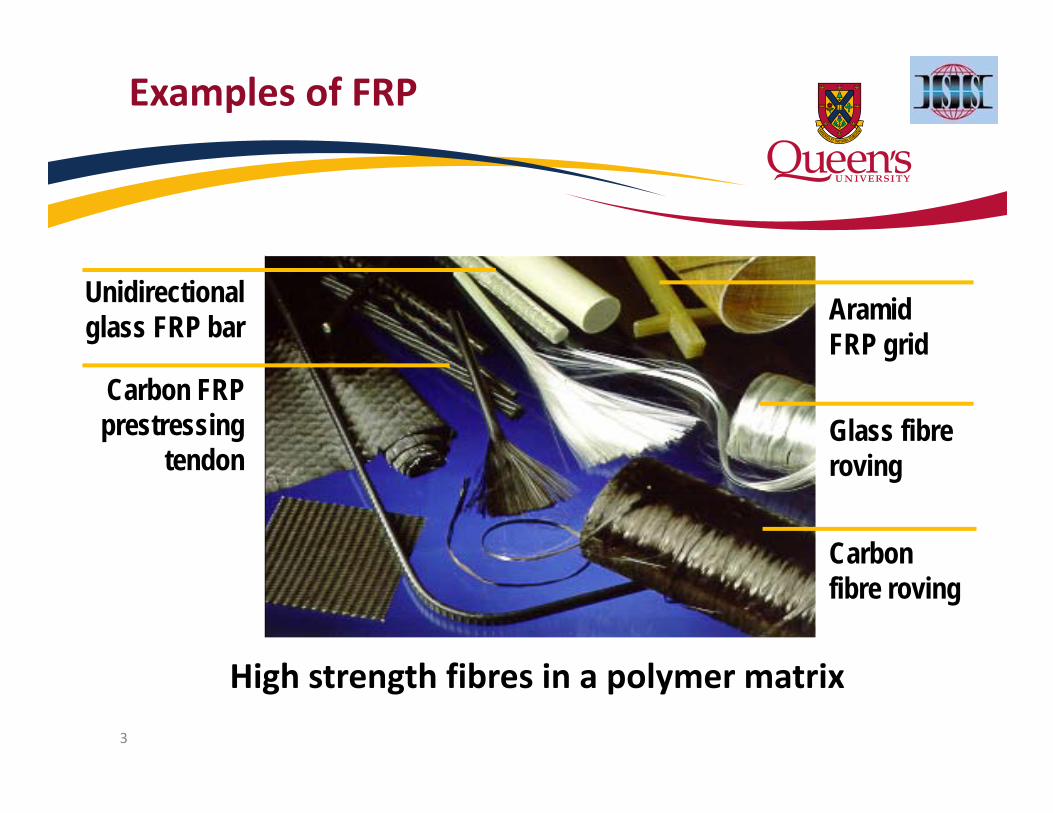
3
Glass fibreroving
Carbon fibre roving
Unidirectional glass FRP bar
Carbon FRP prestressing
tendon
Aramid FRP grid
Examples of FRP
High strength fibres in a polymer matrix

4
FRPs & Fire: Primary Concerns
• Fire is recognized as a critical research need for FRP:– a primary factor preventing widespread application
of FRPs in buildings
• Potential concerns during fire:1. Loss of strength and stiffness2. Loss of interaction (bond) w/ concrete3. Smoke generation and flame spread

Current 440F Repair Guidelines ‐ Fire
• “The strength of externally bonded FRP systems is assumed to be lost completely… unless it can be demonstrated that the FRP temperature remains below its critical temperature (for example, FRP with a fire-protection system)”
• “The critical temperature of an FRP strengthening system should be taken as the lowest glass-transition temperature Tg of the components of the repair system,”
• “The structural member without the FRP system should possess sufficient strength to resist all applicable service loads during a fire” (1.0DL + 1.0LL)
• “The fire endurance of FRP-strengthened concrete members may be improved through the use of certain resins, coatings, insulation systems, or other methods of fire protection”
• Reference is made to ACI 216R guidelines 5

Proposed 440F Repair Guidelines ‐ Fire
• “The strength of externally bonded FRP systems is assumed to be lost completely in a fire, unless it can be demonstrated that the FRP will remain effective for the required duration of the fire (for example, FRP with a fire-protection system).”
• “In most cases, the structural member without the FRP system should possess sufficient strength to resist applicable service loads during a fire” (1.2DL + 0.5LL + 0.2SL + 1.0Ak)
• “The resistance should be computed for the time period required by the member’s fire-resistance rating—for example, a 2-hour fire rating—and should not account for the contribution of the FRP system unless the continued effectiveness of the FRP can be proven through testing.”
• “Until better information on the properties of FRP at high temperature isavailable, the critical temperature can be taken as the lowest Tg of the components of the system.”
6

Rationale for new load factors
• Old load factors for fire (1.0DL + 1.0LL) are based on ASTM E119 provisions for fire testing (no statistical basis)
• New ASCE 7 load factors are based on probabilistic studies and are applicable for new structures (Ellingwood)1
–New loads have less than 5% probability of being exceeded in a given year
–Average live load is 0.6 kPa or 12 psf (approx. 0.25 LL)
71 Ellingwood, private communication with Tarek Alkhrdaji (August 2014)

Comparison of Loading Combinations
8
0.0
0.5
1.0
1.5
2.0
2.5
3.0
3.5
0.0 0.2 0.4 0.6 0.8 1.0 1.2 1.4 1.6 1.8 2.0
Load
in Fire
Con
ditio
n
Live Load to Dead Load Ratio (LL/DL)
216/E119 440F/ASCE
200 mm (8 in.) slab with 2.4 kPa (50 psf) loading
200 mm (8 in.) slab with 4.8 kPa (100 psf) loading
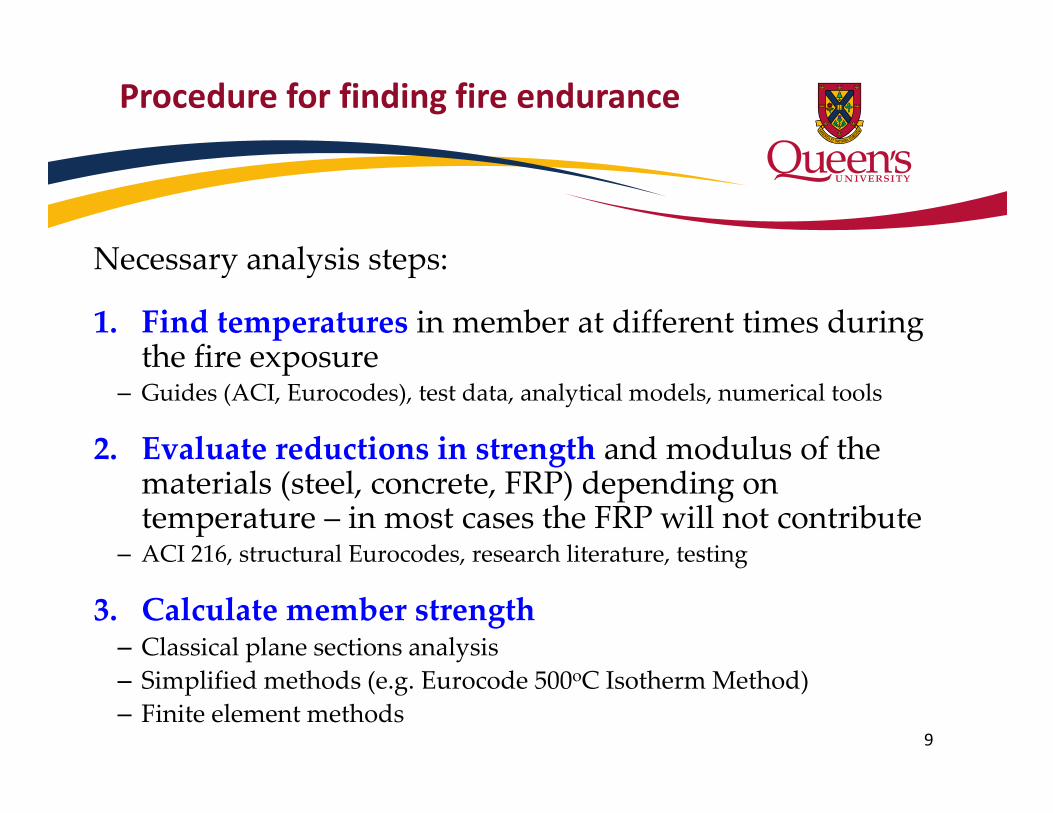
Procedure for finding fire endurance
Necessary analysis steps:
1. Find temperatures in member at different times during the fire exposure
– Guides (ACI, Eurocodes), test data, analytical models, numerical tools
2. Evaluate reductions in strength and modulus of the materials (steel, concrete, FRP) depending on temperature – in most cases the FRP will not contribute
– ACI 216, structural Eurocodes, research literature, testing
3. Calculate member strength– Classical plane sections analysis– Simplified methods (e.g. Eurocode 500oC Isotherm Method)– Finite element methods
9

Philosophy for Fire‐Safety
Temp.(ºC)Load
Time
Initial Service Life Retrofitted Life
Strength
Service Load
Fire Event (hrs)0 1 2 3 4
1000
100
Retrofit
Fire Event Onset
Construction

Conceptual design approach
Fire resistance
Flame spreadprotectionAmou
nt of Stren
gthe
ning
Protect FRP Itself

Design example (after ACI 440.2R)
12
(610 mm)
(305 mm)
(34.5 MPa)
(414 MPa)
(361 kN.m)
As = 3.0 in2 (1935 mm2)

Analysis Approach and Assumptions
13
1. Find temperatures at key locations– FRP – determined from furnace gas temperature– Steel reinforcement – determined from ACI 216 – Concrete compressive stress block – determined from ACI 216
900 F (480 C)
ACI 216 ‐ 2 hours

Analysis Approach and Assumptions
14
1. Find temperatures at key locations– FRP – determined from furnace gas temperature– Steel reinforcement – determined from ACI 216 – Concrete compressive stress block – determined from ACI 216
2. Evaluate reductions in material strengths– FRP – determined from Green et al. (2014) Bisby et al. (2005)– Steel Reinforcement – determined from ACI 216– Concrete compressive stress block – determined from Eurocodes
0.0
0.5
1.0
0 100 200 300 400 500 600 700Redu
ction factor
Temperature (°C)
FRP Strength FRP Modulus FRP Bond Steel Strength
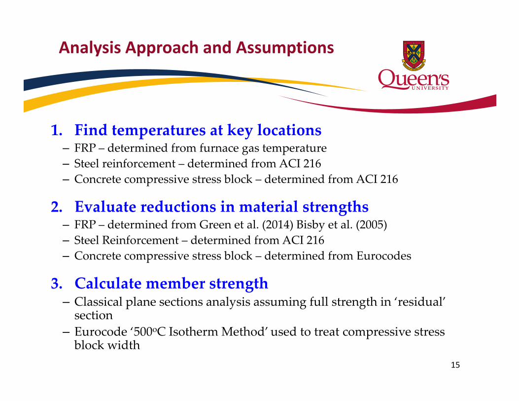
Analysis Approach and Assumptions
15
1. Find temperatures at key locations– FRP – determined from furnace gas temperature– Steel reinforcement – determined from ACI 216 – Concrete compressive stress block – determined from ACI 216
2. Evaluate reductions in material strengths– FRP – determined from Green et al. (2014) Bisby et al. (2005)– Steel Reinforcement – determined from ACI 216– Concrete compressive stress block – determined from Eurocodes
3. Calculate member strength– Classical plane sections analysis assuming full strength in ‘residual’ section
– Eurocode ‘500oC Isotherm Method’ used to treat compressive stress block width

Unstrengthened beam in fire
16
* Fire Resistance > 3.0 hours
LL/DL = 1.2
050100150200250300350400450500
0.0 0.5 1.0 1.5 2.0 2.5 3.0
Mom
ent (kN
.m)
Time (hours)
Mr 216/E119 440/ASCE
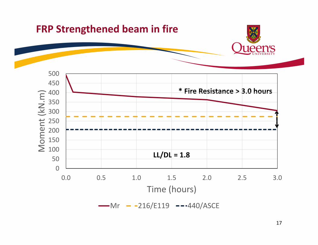
FRP Strengthened beam in fire
17
* Fire Resistance > 3.0 hours
LL/DL = 1.8
050
100150200250300350400450500
0.0 0.5 1.0 1.5 2.0 2.5 3.0
Mom
ent (kN
.m)
Time (hours)
Mr 216/E119 440/ASCE
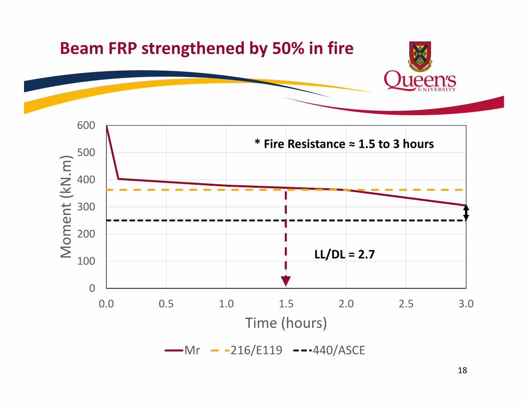
0
100
200
300
400
500
600
0.0 0.5 1.0 1.5 2.0 2.5 3.0
Mom
ent (kN
.m)
Time (hours)
Mr 216/E119 440/ASCE
Beam FRP strengthened by 50% in fire
18
* Fire Resistance ≈ 1.5 to 3 hours
LL/DL = 2.7
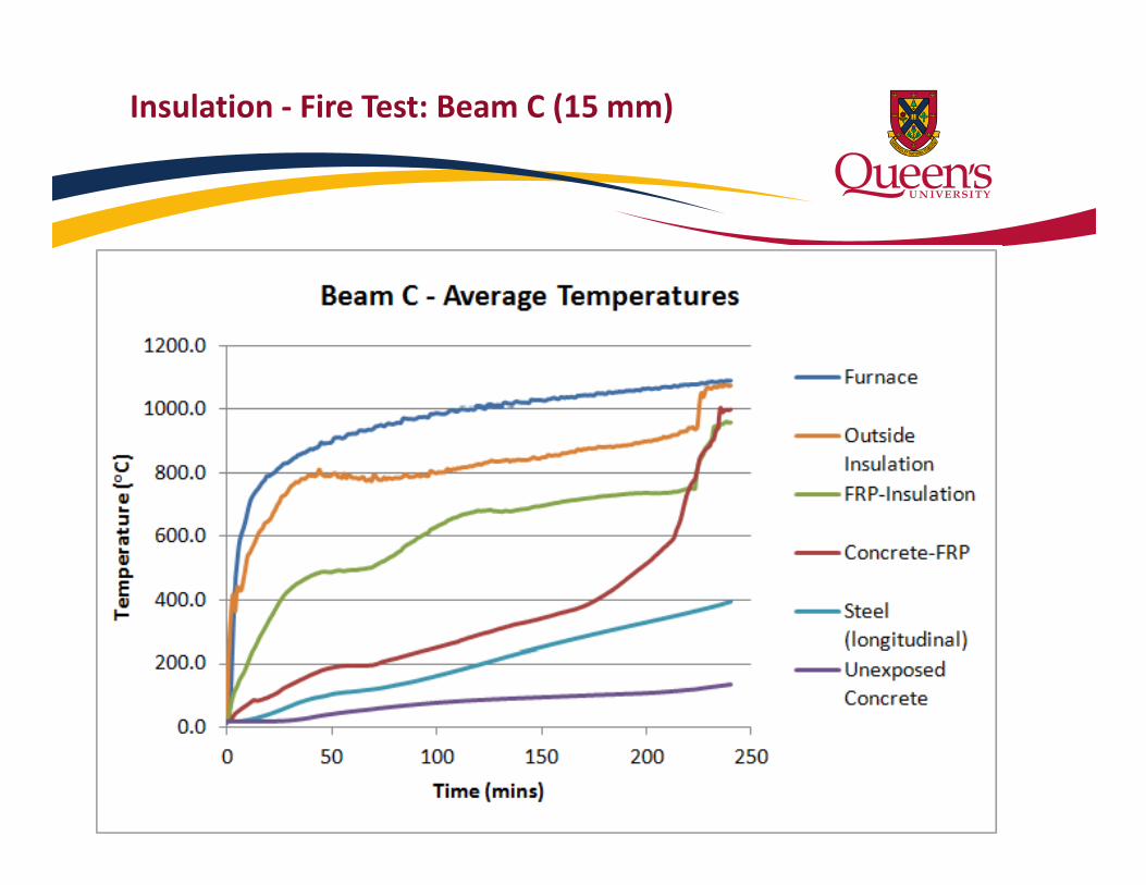
Insulation ‐ Fire Test: Beam C (15 mm)
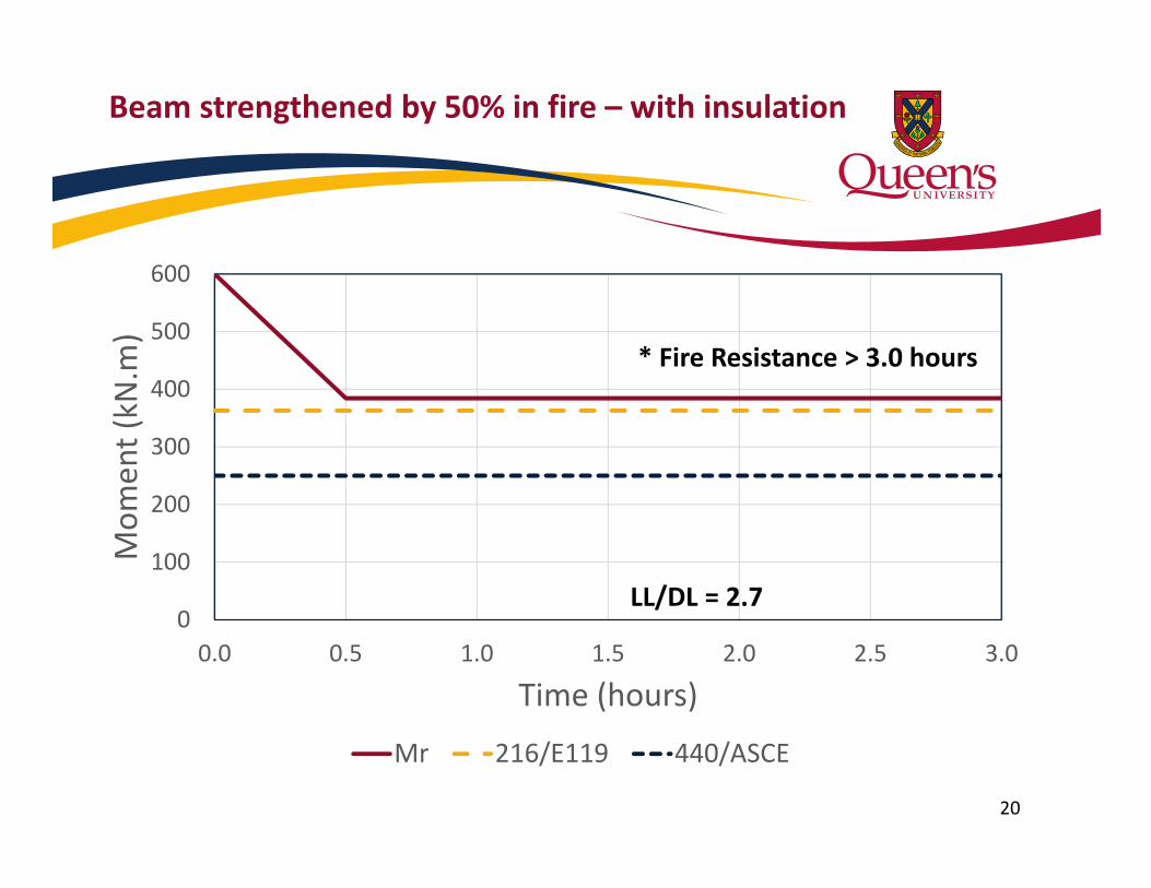
Beam strengthened by 50% in fire – with insulation
20
0
100
200
300
400
500
600
0.0 0.5 1.0 1.5 2.0 2.5 3.0
Mom
ent (kN
.m)
Time (hours)
Mr 216/E119 440/ASCE
LL/DL = 2.7
* Fire Resistance > 3.0 hours

Conclusions
• ACI 440.2R is proposing to modify the load demand equation for the fire limit state to harmonize with ACI 562 and ASCE 7
1.0DL + 1.0LL
1.2DL + 0.5LL + 0.2SL + 1.0Ak
• Practical guidance has been given on how to determine the fire resistance of FRP strengthened beams, with or without supplemental fire insulation
• In most cases it is possible for FRP strengthened concrete structural elements to achieve satisfactory fire resistances

Acknowledgements
• Natural Sciences and Engineering Research Council of Canada (NSERC)
• Leverhulme Trust
22
