rational rose notes – werner - myweb at witmyweb.wit.edu/wernerm/rationalrosenotes.doc · web...
TRANSCRIPT

A simple tutorial on using rational rose and UML
Michael M Werner
2003 All rights reserved
Rational Rose Tutorial 1 5/8/2023

IntroductionUnified Modeling Language (UML) was created in 1995 by merging diagramming conventions used by three software development methodologies: OMT by James Rumbaugh, Objectory by Ivar Jacobson and the Booch Method by Grady Booch. Prior to this time, these three amigos, along with about a dozen other practitioners had promoted competing methodologies for systematic software development, each with its own system of diagramming conventions. The methodologies followed a kind of cookbook style of pushing a software project through a succession of life cycle stages, culminating with a delivered and documented application. One goal of UML was to reduce the proliferation of diagramming techniques by standardizing on a common modeling language, thus facilitating communication between developers. It achieved that goal in 1997 when the (international) Object Management Group (OMG) adopted it as a standard.
Some critics consider that UML is a bloated diagramming language written by a committee. That said, I consider it to be the best means available today for documenting object-oriented software development. It has been and is becoming increasingly used in industry and academia.
It should be stressed that UML is not a methodology, rather it is a language for expressing software models. Conceivably, it can be used with various software methodologies. However, separately from the UML, the three amigos have developed the Rational Unified Process, a methodology that is use case driven, and carried out using UML models.
Rational Rose is a Computer Aided Software Engineering (CASE) tool developed by the Rational Corporation under the direction of Booch, Jacobson and Rumbaugh to support software development using UML. Rational Rose is necessarily complex owing to its mission of fully supporting UML. In addition, Rational Rose has numerous language extensions to Ada, C++, VB, Java, J2EE, etc. Rational Rose supports forward and reverse engineering to and from these languages. On the other hand, Rational Rose does not support some traditional design techniques as data flow diagrams and CRC cards, since these are not part of UML.
Because Rational Rose has so many capabilities it is a daunting task to master it. Fortunately, a lot can be done using just a small subset of these capabilities. These notes are designed to introduce novice developers into making productive use of such a subset. They reflect the author’s bias towards developing software and should not be taken as the last word on the subject.
Rational Rose Views Related to the Software Development Life Cycle
Rational Rose models have these four views:
Rational Rose Tutorial 2 5/8/2023

1. Use Case View2. Logical View3. Component View4. Deployment View
I like to use a Software Development Life Cycle with these phases:
0. Project Initiation1. Requirements2. Design
2.1 Architectural Design2.2 Detail Design
3. Implementation 4. Maintenance
0. Project Initiation
The project initiation phase involves identifying a problem that need a software solution, investigating to see if an adequate solution is already available for purchase, if not, working up an informal proposal outlining new software to be built and making the case that the expected benefits justify the cost. Rational rose need not be involved in this phase.
1. Requirements
The requirements phase involves eliciting requirements from the client and presenting them in a formal contractual document that will later serve as the basis for acceptance of the finished project. Getting the requirements right is key to the success of the project. However, the software developers are usually not expert on the client’s business environment, nor are the clients necessarily good at expressing what their real requirements are. The developers need to work with the clients to determine the real requirements.
Use Case Diagram - The best tool I know of for talking about requirements is the use case diagram, developed by Jacobson. The diagrams and the use case technique are so simple that clients instantly relate to them and will readily volunteer usual and exceptional scenarios to go along with each use case. The use cases are recorded in the use case view of rational rose.
Some other diagrams strictly speaking belong to the design phase, but may also be useful in the requirements phase. They are constructed in Rational Rose’s Logical View.
Rational Rose Tutorial 3 5/8/2023

Class Diagram – As part of the requirements process entity classes are identified and described in terms of attributes, operations and associations using the UML class diagram. A class is an entity class if it forms part of the client’s business model. So, for example, if the client is running a hospital, possible entity classes are: Patient, Doctor, Nurse, Therapist, Bed, Treatment, Diagnosis, etc. On the other hand, classes such as Form, Canvas, Button, Socket, etc. are not entity classes. They are classes needed to implement the solution, but are not meaningful in describing the client’s business, hence not part of the requirements phase.
Another way to look at entity classes is from a database point of view. The entity classes are usually the persistent ones, i.e. they describe the objects, which the system will permanently track in a database.
Sequence Diagram (Logical View)– Object-Oriented systems get work done by sending messages between objects, invoking functions to obtain services. Sequence diagrams are designed to help visualize the messaging. Each use case results in one or more sequence diagrams, a main sequence diagram to illustrate the usual scenario for the use case and zero or more additional sequence diagrams to illustrate exceptional scenarios. One or two sequence diagrams are appropriate in the requirements phase; they are helpful in refining and adding to use cases, and discovering entity classes. The bulk of sequence diagrams belong to the design phase.
Component and Deployment diagrams are primarily used in the architectural design phase. They show the division of software responsibilities into software components or modules, and the deployment of modules to various devices. However, for some projects such as web applications, client-server and multi-tiered configurations, etc. these issues are so important that the developer may wish to discuss them with the client during requirements analysis. In Rational Rose, these diagrams properly belong in the Component and Deployment views, respectively.
2.1 Architectural DesignThe architectural design phase is used to divide up system responsibilities into subsystems. The subsystems (modules) are identified, responsibilities assigned to them, and interfaces between modules are specified. A general scheme for the software architecture is chosen. For example: client/server, layered services, model-view-controller, etc. The data model is refined including levels of access for different actors.
The following UML diagrams are useful at this stage: Class Diagram (Logical View) – Classes are grouped into packages representing
subsystems.
Rational Rose Tutorial 4 5/8/2023

Component Diagram (Component View) – Components and interfaces are defined.
Deployment Diagram (Deployment View) – Software components are mapped to hardware components.
2.2 Detail DesignThe modules identified in architectural design need to be fully specified prior to implementation.
The following UML diagrams are useful at this stage: Class Diagram (Logical View) – Entity classes were identified by analyzing the
problem space during the requirements phase. These are now supplemented with additional solution classes needed to build interfaces, maintain persistent data, manage communications, etc.
The expanded class diagram is reexamined to take advantage of factoring out common behavior into abstract superclasses, simplify associations and otherwise make the design more cohesive.
Sequence Diagram (Logical View) – A complete set of sequence diagrams is now drawn for each of the use cases identified as requirements. As mentioned earlier, each use case has a usual scenario and perhaps several exceptional scenarios. Rather than attempt to show branching in the sequence diagrams, usually a separate diagram is drawn for each scenario.
Statechart Diagram (Logical View) – The state of an object is the current set of values of all its attributes (including inherited ones). Objects may change state in response to messages received. The statechart diagram shows all the states, transitions between states labeled by the messages, which cause them, and guards on transitions.
Activity Diagram (Logical View) – These diagrams are similar to the familiar flowcharts. They show activities (processes) and the flow of control and data between activities.
Together the sequence, statechart and activity diagrams form the dynamic model of the system. In general, the system is at rest until an actor initiates a use case by requesting a system function. This causes a flurry of messages and state changes as predicted by the dynamic model.
3. Implementation
In the implementation phase the detailed design is actually carried out in program code using a target language. Data definition language is written to create and populate the database tables and grant role-based privileges. Reports and interactive forms are written, as well as help files and exception handling routines.
Rational Rose Tutorial 5 5/8/2023

The implementation phase is characterized by testing, unit tests to see if individual modules work correctly, integration tests to ensure that the modules work together properly to carry out the use cases. Tested modules are deployed to the target hardware and retested on site. Finally, acceptance testing verifies that the system carries out its various functions correctly, i.e. according to their specification in the requirements document.
Rational Rose provides extensive support for implementation:
Model checking. Forward code generation (from model to source code) in a variety of target
languages.
4. Maintenance
Rational Rose Tutorial 6 5/8/2023

Using Rational Rose and UML to Build a Library Circulation System
The Problem:
A public library would like to automate some of its circulation functions. Machines will be purchased so that library customers will be able to check out and return books on their own. As with any library, customers will first need to be approved for a library card. Cardholders will be assigned (or select) a username and password. To borrow a book, a cardholder enters her username and password, then scans each book they wish to borrow. The books are desensitized. When done, the cardholder presses submit, which logs them off and opens a turnstile gate so they can leave. A similar process is followed when returning a book. The cardholder logs on, scans the books for return, and logs off.
Cardholders may also reserve books using a WWW interface and pay fines or other fees by logging on and using a credit card or payment service. They can request reports on books they currently have on loan and books they have borrowed in the past.
Circulation librarians can send reminders to cardholders, create a variety of reports to track borrowers, books, loans, etc. and levy fines. Acquisitions librarians acquire new books and add them to the system. Likewise they may dispose existing books and remove them from the system. They can generate reports on loans and reservations to help guide their decisions.
Step 1 – Create a use case diagram in Rational Rose
Start Rational Rose.
Rational Rose Tutorial 7 5/8/2023

Choose a default language. This is the language you plan to develop in. I chose J2EE, since I plan to make a Java application. This is the browser window. You will create a model by adding various artifacts such as use cases, diagrams, classes, etc. to it. All artifacts are accessible from the browser whether they are shown in diagrams or not.
Note that the browser window also shows the four rational rose views, discussed earlier. The model properties are the settings for generating code in the various target languages. You can double click the icon in the browser window to change these, or select Model Properties from the Tools menu.
Rational Rose Tutorial 8 5/8/2023

Creating the use case view:
It is convenient to group model artifacts into packages. Since the target language in this case, Java, directly supports packages this is a good idea. Right-clicking on package icons in the browser brings up the new menu, which allows creating various new artifacts in the package.
Create a new package and name it Circulation. Add actors and use cases to the circulation package by right clicking on the package name and choosing new. Each actor and use case should be described in the documentation window, usually located in the lower left of your screen. Add a new use case diagram to the Circulation package, name it Main, and drag actors and use cases onto it. Choose the unidirectional association tool and drag from the actor to the use case. Now create a use case diagram for the library circulation system.
Start with typical usages such as borrowing and returning a book. Identify the actors involved, for example library cardholders and circulation librarians. Think of the different titles we use for librarians and whether their job descriptions include using the library circulation system in some way. Don’t neglect boundary conditions. These include startup, shutdown and handling exceptions. How will new books be entered into the system and old ones removed? Usually an acquisitions librarian is in charge and will have use cases for acquiring and disposing of books. Similarly, think of how library users will apply for and be issued library cards, and possibly lose borrowing privileges if they fail to comply with library rules. Here is a sample use case diagram.
Rational Rose Tutorial 9 5/8/2023

ApplyForCard
Borrow
Return
Reserve
PayFee
Renew
UpdateProfile
AcquireBook
DisposeBook
Cardholder
Acquisitions Librarian
Remind
Manage Card Holders
FineCardHolder
GetReports
Login
ApproveLibraryCard
SuspendLibraryCard
Circulation Librarian
Public User
BrowseTitles
No code will be generated from the use cases so don’t agonize over getting them exactly right. UML provides for <<include>> and <<extend>> associations between use cases. The << … >> notation stands for a UML stereotype. <<include>> is a standard stereotype to indicate that one use case, say Login, is included as a common part of other
Rational Rose Tutorial 10 5/8/2023

use cases. <<extend>> is used to handle exceptional conditions. Here is a diagram illustrating use case associations.
The dotted arrows are used for dependencies between use cases. Double clicking on an arrow brings up its specification window. You can choose a standard stereotype or type in a new one. This is part of UML’s extensibility feature.
Bear in mind that the main purpose of use cases is to be able to review them with your client so as to get the requirements right. Later we will see that they play a role in discovering domain classes and in drawing class and sequence diagrams.
Scenarios
A scenario is basically a flow of events that occur when a use case is carried out. The scenario should have entry and exit conditions, plus a list of steps that are followed. Associated with each use case is the usual scenario if everything goes right and several exceptional scenarios followed if something goes wrong. Rational Rose does not supply specific support for storing scenarios. There are thus two choices: (1) Write the scenarios in the documentation window for the use case, or (2) attach a file to the use case containing the scenarios. Keep the language simple so that your clients can understand and work with you on the scenarios. Here is an example of writing the scenarios for the borrow use case in the documentation window.
Rational Rose Tutorial 11 5/8/2023
By the way, it is time to save your model if you haven’t already done so. Choose Save As from the file menu, and specify a name and location. This will also give a name to the model.
Step 2 – Create a class diagram in Rational Rose
Even though you are still in the Requirements Phase of development, it is appropriate to start creating a class diagram. The initial classes are so-called entity classes, that is classes that correspond to entities in your client’s business model. So, for a library circulation system the entity classes will include Book, Cardholder, Loan, etc. Later on, in the Design Phase, the entity classes will be supplemented with solution classes.
In Rational Rose, class diagrams form part of the logical view. As before, we will group the entity classes in a package. Right click on the Logical View, create a new package and name it Circulation. Drag the Circulation package into the Package Hierarchy diagram, where it joins other packages such as java and javax, which were placed there when you chose to build a J2EE application.
Rational Rose Tutorial 12 5/8/2023

Add classes to the Circulation package by right clicking on the package name and choosing new. Add a Class Diagram to the Circulation package, and label it Main,
Add a class for each entity object in the library circulation system. Add attributes to each class by right-clicking on the class and pressing new. You
can follow the attribute name by a colon and a type as in: balance:double. Alternatively, you can open the specification for the attribute to assign a Java type to it. Although the Type field is grayed, you can click on the … button and bring up the Select a type window.
Rational Rose Tutorial 13 5/8/2023

Add operations. Open the specification for each operation to add parameters to it. Add associations between classes. Open the specification for each association. It
is important to add multiplicities and role names for each association using the tabs entitled “Role A detail” and “Role B detail”. The role names will be used in code generation.
I created the following class diagram for the library circulation system.
Rational Rose Tutorial 14 5/8/2023

Personusername : Stringpassword : Stringname : String
Librarian Titleisdn : StringbookTitle : Stringauthor : StringcopiesAvailable : int
Title()adjustAvailable()isAvailable()
ReservationreserveDate : java.sql.Date
Reservation()
1
0..n
+title
1
+reservation
0..n
ReturnControl
recordReturn()opname()
CardholderaccountBalance : double
borrowBook()returnBook()reserve()Cardholder()
0..n
1
+reservations
0..n+reserver
1
BookcopyNum : int
Book()borrow(loan : Loan)
0..n
1
+book
0..n
+title
1
copy of
LoanborrowDate : java.sql.DatereturnDate : java.sql.DateloanNumber : int
Loan()returnBook()
0..n
1
+loan0..n
+borrower1
borrows
10..n
+book
1
+loan
0..n
LoanControlname
recordBorrow(isdn : String, copy : int) : intreserve(isdn : String) : int
0..n
1
+loan 0..n
+controller 1
controls
Step 3 – Create sequence diagrams in Rational Rose
Like class diagrams, sequence diagrams are placed in the logical view. Remember the use case scenarios from the use case view. It is now time to express each of these scenarios in terms of message passing between objects belonging to classes described in the class diagram(s). Properly, sequence diagrams belong to the design phase, since we are beginning to talk about the solution space, rather than the problem space. However, it is appropriate to include one or two sequence diagrams in the requirements phase.
In the browser, right-click on the Circulation package to add a new sequence diagram. To illustrate, I will draw a sequence diagram for the borrow use case – usual scenario.Drag the Cardholder actor into the diagram from the use case model. Now drag in needed objects from the classes defined in the Circulation package. Create messages with the Object Message tool, dragging from the source object to the target. The message name and signature should match with an operation available in the target class, in fact right-clicking on a message arrow reveals a list of target class operations to choose from. Alternatively, you can add a new operation to the target class. It will show up in the class diagram.
Rational Rose Tutorial 15 5/8/2023

: Cardholder : Cardholder : LoanControl : Loan : Title : Book
borrowBook(String, int)
recordBorrow(String, int)Loan( String, int)
adjustAvailable()
borrow(Loan)Receipt
Sequence diagram showing messaging involved in borrowing a book. The flesh and blood cardholder logs on to the system activating her Cardholder surrogate object. The Cardholder checks to see if it is in good standing. If so it sends a borrow message to the waiting LoanControl process along with book id information scanned from a bar code. The LoanControl takes charge, creating a Loan object to record the loan, sending a reference to the loan object to the Book object, decrementing the copiesAvailable count in the Title object, and finally printing a loan receipt for the cardholder.
Borrow Book Sequence Diagram - M Werner Feb '03
Use Case Diagram: Circulation / Main
Class Diagram: Circulation / Main
Discussion of control classes here
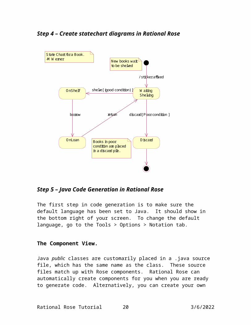
Step 4 – Create statechart diagrams in Rational Rose
Rational Rose Tutorial 16 5/8/2023

OnShelf
OnLoan
Waiting Shelving
borrow return
shelve[ (good condition) ]
Discard
discard[ Poor condition ]
/ sticker affixed
State Chart for a Book.-M Werner New books wait
to be shelved
Books in poor condition are placed in a discard pile.
Step 5 – Java Code Generation in Rational Rose
The first step in code generation is to make sure the default language has been set to Java. It should show in the bottom right of your screen. To change the default language, go to the Tools > Options > Notation tab.
The Component View.
Java public classes are customarily placed in a .java source file, which has the same name as the class. These source files match up with Rose components. Rational Rose can automatically create components for you when you are ready to generate code. Alternatively, you can create your own components and in the browser, drag classes into them. You need to do this for non-public java classes.
For the Library application it is natural to carry over the packages from the logical view. So, add a package named Circulation to the component view. When you generate code from a class for the first time, you will create a component for it in the Circulation package.
Rational Rose Tutorial 17 5/8/2023

Setting Java Properties.
The java code that is generated depends on the settings of the java properties for the model. You can double-click the Model Properties from the browser window or choose Tools > Model Properties > Edit from the menu. Select the Java tab. In the Type window, choose the artifact you wish to set properties for. Here is the window when Attribute is selected.
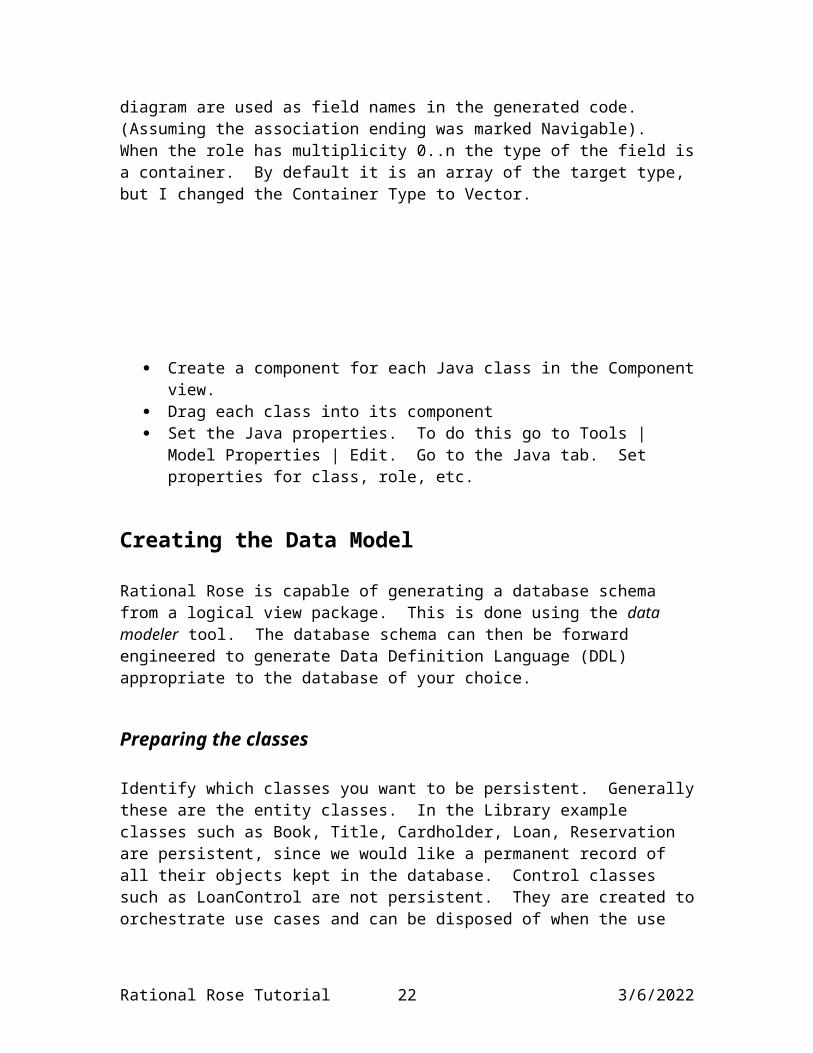
The only change I made on this screen was to change PropertyType to Simple. This is a bean property. Simple means that get and set methods are generated for each attribute. I made the same change for the Role type. Recall that the role names you specified in the class diagram are used as field names in the generated code. (Assuming the association ending was marked Navigable). When the role has multiplicity 0..n the type of the field is a container. By default it is an array of the target type, but I changed the Container Type to Vector.
Create a component for each Java class in the Component view. Drag each class into its component Set the Java properties. To do this go to Tools | Model Properties | Edit. Go to
the Java tab. Set properties for class, role, etc.
Rational Rose Tutorial 18 5/8/2023

Creating the Data Model
Rational Rose is capable of generating a database schema from a logical view package. This is done using the data modeler tool. The database schema can then be forward engineered to generate Data Definition Language (DDL) appropriate to the database of your choice.
Preparing the classes
Identify which classes you want to be persistent. Generally these are the entity classes. In the Library example classes such as Book, Title, Cardholder, Loan, Reservation are persistent, since we would like a permanent record of all their objects kept in the database. Control classes such as LoanControl are not persistent. They are created to orchestrate use cases and can be disposed of when the use cases complete. Similarly boundary classes, which house interface forms and scripts need not be persistent.
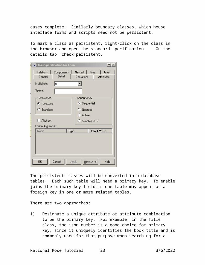
To mark a class as persistent, right-click on the class in the browser and open the standard specification. On the details tab, check persistent.
Rational Rose Tutorial 19 5/8/2023
The persistent classes will be converted into database tables. Each such table will need a primary key. To enable joins the primary key field in one table may appear as a foreign key in one or more related tables.
There are two approaches:
1) Designate a unique attribute or attribute combination to be the primary key. For example, in the Title class, the isbn number is a good choice for primary key, since it uniquely identifies the book title and is commonly used for that purpose when searching for a book. In the Book class, the combination (concatenation) of isbn and copy number makes a natural primary key. However, there is a cost to doing this. The isbn needs to be saved as a character string, which takes up more space than a simple integer. The space issue is even worse in the Loan table, which will need to store both the isbn and the copy number to recognize the relationship of a loan to a specific book. Another problem is that joins between related tables may be slower, since string comparisons take longer than integer comparisons, and comparisons of concatenated keys take longer still.
2) Allow the data modeler to generate a new integer-valued primary key id for the table. Although these auto-generated id’s are not meaningful to end-users, they do save space and make for fast joins.
To designate an attribute to be part of the primary key, right-click on the attribute in the browser, select Data Modeler, part of Object Identity.
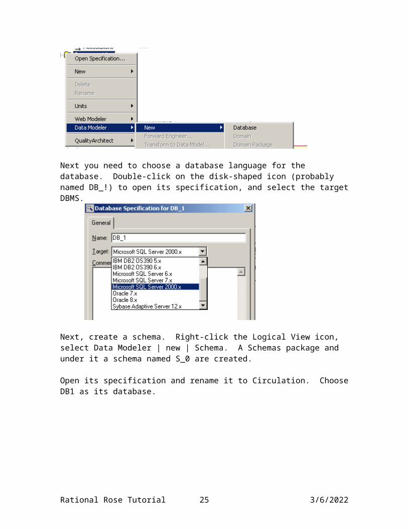
You now need to set up a database component. Right-click on the Component View icon, select Data Modeler | New | Database.
Rational Rose Tutorial 20 5/8/2023

Next you need to choose a database language for the database. Double-click on the disk-shaped icon (probably named DB_!) to open its specification, and select the target DBMS.
Next, create a schema. Right-click the Logical View icon, select Data Modeler | new | Schema. A Schemas package and under it a schema named S_0 are created.
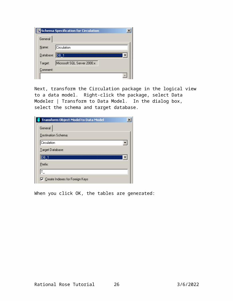
Open its specification and rename it to Circulation. Choose DB1 as its database.
Next, transform the Circulation package in the logical view to a data model. Right-click the package, select Data Modeler | Transform to Data Model. In the dialog box, select the schema and target database.
Rational Rose Tutorial 21 5/8/2023
When you click OK, the tables are generated:
Right-click on the Circulation schema in the browser, select Data Modeler | New | Data Model Diagram. Rename the diagram to Main. Open it up and drag all the tables into it. Drag them around to improve readability. You get something like:
Rational Rose Tutorial 22 5/8/2023
T_BookEJBcopyNum : INTEJB_Context : SMALLINTT_BookEJB_ID : INTT_Title_ID : INT
<<PK>> PK_T_BookEJB23()<<FK>> FK_T_BookEJB25()<<Index>> TC_T_BookEJB306()
T_Titleisbn : VARCHAR(255)bookTitle : VARCHAR(255)author : VARCHAR(255)copiesAvailable : INTT_Title_ID : INT
<<PK>> PK_T_Title24()
1
0..*
1
0..*
<<Non-Identifying>>
T_LoanborrowDate : SMALLINTreturnDate : SMALLINTloanNumber : INTT_Loan_ID : INTT_BookEJB_ID : INTT_Person_ID : INT
<<PK>> PK_T_Loan25()<<FK>> FK_T_Loan27()<<FK>> FK_T_Loan24()<<Index>> TC_T_Loan304()
10..* 10..*
<<Non-Identifying>>
T_ReservationreserveDate : SMALLINTT_Reservation_ID : INTT_Title_ID : INTT_Person_ID : INT
<<PK>> PK_T_Reservation26()<<FK>> FK_T_Reservation28()<<FK>> FK_T_Reservation26()<<Index>> TC_T_Reservation308()
10..* 10..*
<<Non-Identifying>>
T_LibrarianT_Person_ID : INT
<<PK>> PK_T_Librarian28()<<FK>> FK_T_Librarian30()
T_CardholderaccountBalance : FLOAT(64, 0)T_Person_ID : INT
<<PK>> PK_T_Cardholder27()<<FK>> FK_T_Cardholder29() 1
0..*
1
0..*
<<Non-Identifying>>
10..*
10..*
<<Non-Identifying>>
T_Personusername : VARCHAR(255)password : VARCHAR(255)name : VARCHAR(255)id : VARCHAR(255)T_Person_ID : INT
<<PK>> PK_T_Person20()
1
0..1
1
0..1
<<Identifying>>
1
0..1
1
0..1
<<Identifying>>
Transforming the object model to the data model
In examining the data model above, notice that the following transformations have taken place:
1) An integer-valued ID field was generated for every table that did not have a primary key.
2) 1:n relationships were recognized by adding a foreign key to the table on the n side, to match the primary key of the table on the 1 side.
3) The inheritance association between Cardholder and Person was recognized by having the ID field serve both as a primary key in Cardholder and a foreign key pointing to a unique person object.
Rational Rose Tutorial 23 5/8/2023

Now generate DDL for use in creating the schema:
Right-click on the Circulation schema icon. Select Data Modeler | Forward Engineer to bring up the Forward Engineering wizard. You can accept the defaults. The main thing is to choose a name and location for the DDL file. You can open he generated file in a text editor. I got the following:
CREATE TABLE T_Title (isbn VARCHAR ( 255 ) NOT NULL,bookTitle VARCHAR ( 255 ) NOT NULL,author VARCHAR ( 255 ) NOT NULL,copiesAvailable INT NOT NULL,T_Title_ID INT IDENTITY NOT NULL,CONSTRAINT PK_T_Title24 PRIMARY KEY NONCLUSTERED
(T_Title_ID))
GO
CREATE TABLE T_Librarian (T_Person_ID INT NOT NULL,CONSTRAINT PK_T_Librarian28 PRIMARY KEY NONCLUSTERED
(T_Person_ID))
GO
CREATE TABLE T_BookEJB (copyNum INT NOT NULL,EJB_Context SMALLINT NOT NULL,T_BookEJB_ID INT IDENTITY NOT NULL,T_Title_ID INT NOT NULL,CONSTRAINT PK_T_BookEJB23 PRIMARY KEY NONCLUSTERED
(T_BookEJB_ID))
GO
CREATE TABLE T_Loan (borrowDate SMALLINT NOT NULL,returnDate SMALLINT NOT NULL,loanNumber INT NOT NULL,T_Loan_ID INT IDENTITY NOT NULL,
Rational Rose Tutorial 24 5/8/2023
T_BookEJB_ID INT NOT NULL,T_Person_ID INT NOT NULL,CONSTRAINT PK_T_Loan25 PRIMARY KEY NONCLUSTERED
(T_Loan_ID))
GO
CREATE TABLE T_Cardholder (accountBalance FLOAT ( 64 ) NOT NULL,T_Person_ID INT NOT NULL,CONSTRAINT PK_T_Cardholder27 PRIMARY KEY NONCLUSTERED
(T_Person_ID))
GO
CREATE TABLE T_Reservation (reserveDate SMALLINT NOT NULL,T_Reservation_ID INT IDENTITY NOT NULL,T_Title_ID INT NOT NULL,T_Person_ID INT NOT NULL,CONSTRAINT PK_T_Reservation26 PRIMARY KEY NONCLUSTERED
(T_Reservation_ID))
GO
CREATE TABLE T_Person (username VARCHAR ( 255 ) NOT NULL,password VARCHAR ( 255 ) NOT NULL,name VARCHAR ( 255 ) NOT NULL,id VARCHAR ( 255 ) NOT NULL,T_Person_ID INT IDENTITY NOT NULL,CONSTRAINT PK_T_Person20 PRIMARY KEY NONCLUSTERED
(T_Person_ID))
GOCREATE INDEX TC_T_BookEJB306 ON T_BookEJB (T_Title_ID)GOCREATE INDEX TC_T_Loan304 ON T_Loan (T_BookEJB_ID)GOCREATE INDEX TC_T_Reservation308 ON T_Reservation (T_Title_ID)GOALTER TABLE T_Librarian ADD CONSTRAINT FK_T_Librarian30 FOREIGN KEY (T_Person_ID) REFERENCES T_Person (T_Person_ID)
Rational Rose Tutorial 25 5/8/2023
GOALTER TABLE T_BookEJB ADD CONSTRAINT FK_T_BookEJB25 FOREIGN KEY (T_Title_ID) REFERENCES T_Title (T_Title_ID) GOALTER TABLE T_Loan ADD CONSTRAINT FK_T_Loan24 FOREIGN KEY (T_BookEJB_ID) REFERENCES T_BookEJB (T_BookEJB_ID) GOALTER TABLE T_Loan ADD CONSTRAINT FK_T_Loan27 FOREIGN KEY (T_Person_ID) REFERENCES T_Cardholder (T_Person_ID) GOALTER TABLE T_Cardholder ADD CONSTRAINT FK_T_Cardholder29 FOREIGN KEY (T_Person_ID) REFERENCES T_Person (T_Person_ID) GOALTER TABLE T_Reservation ADD CONSTRAINT FK_T_Reservation26 FOREIGN KEY (T_Title_ID) REFERENCES T_Title (T_Title_ID) GOALTER TABLE T_Reservation ADD CONSTRAINT FK_T_Reservation28 FOREIGN KEY (T_Person_ID) REFERENCES T_Cardholder (T_Person_ID) GO
It is a good idea to record the name of the file in the documentation for the schema.
Rational Rose Tutorial 26 5/8/2023