rb4000 commercial & industrial regulator - istec corp · rb4000 commercial & industrial...
TRANSCRIPT

RB4000 Commercial & Industrial Regulator
Advanced Meteringand RegulationTechnology at Work

FeaturesDirect acting spring-loadedpressure regulator
• Balanced Valve Design• Fluids: Natural gas, propane,
butane, air, nitrogen, etc.• Built-in pulsation damper• Suited for both vertical and
horizontal applications• Available with silencer• Available with High and/or
Low pressure shut-off valve• Built-in bypass system for
ease of shut-off reset
BenefitsThe RB4000 series has thefollowing benefits:• Reduced overall
dimensions/high capacity• Easy Maintenance• Boosting mechanism gives
"fixed-factor" regulation forindustrial application
• Rugged construction fordurability
• Balanced valve designeliminates inlet pressureeffect
• Fast-acting for sharp On/OffLoads
ApplicationThe Series RB4000 pressureregulator is designed for gassupply networks, districtstation regulation, industrialservice regulation, and allapplications where accuratepressure control, ease ofadjustment, and fast responseare required such as forburners, industrial ovens,boilers, etc.
Upstream pressureDownstream pressure
1
Operating Sketch
ConstructionBody : Ductile iron quality 500-7 UNI-ISO 1083, Steel quality ASTM A 216 WCBInternal parts: Brass and stainless steelDiaphragm Synthetic rubber with fabric reinforcementSeals: Nitrile rubber or Viton (on request)Diaphragm Casing & Cover: UNI/EN 10025 pressed steel

Correction factors fornon-natural gas applications:The RB4000 may be used to controlmaterials other than natural gas. Todetermine the capacity of the RB4000for gases other than natural gas, it willbe necessary to multiply the valueswithin the capacity tables by acorrection factor. The table below liststhe correction factors for some of themore common gases:
Gas Type Specific Correction Gravity Factor (CF)
Air 1.0 0.77Butane 2.01 0.55Carbon Dioxide (Dry) 1.52 0.63Carbon Monoxide (Dry) 0.97 0.79Natural Gas 0.60 1.00Nitrogen 0.97 0.79Propane 1.53 0.63Propane-Air-Mix 1.20 0.71
To calculate the correction factor forgases not listed on the table above, itwill be necessary to know the specificgravity of the gas and use it in theformula listed below:
Correction Factor (CF) = S.G.1
S.G.2
Where:SG1 = Specific Gravity of the gas in
which the capacity is published.SG2 = Specific Gravity of the gas
to be controlled.
For wide-open orifice flow calculations use the following equations: For P1/P2
> 1.89 use: Qmax = K P1 /2 For P1/P2<1.89 use: Q = K P2(P1-P2)
Where: P1 = absolute inlet pressure (psia) P2 = absolute outlet pressure (psia)Q = flow rate (scfh) K = orifice coefficient (scfh/psi)
Inlet Outlet Flanged Orifice Size Wide Open Orifice Coefficient (K)
2" 2" Y 2” 4430
3" 3" Y 3” 8540
VALVE BODY SIZES
Y indicates that the valve body is available in that configuration
2
Specifications
* Please specify valve body material on your order (Ductile Iron or Steel).
**Multiply capacity data by 0.7 when using shut-off valve versions.
Available Vent Sizes: 1/4" NPTOperating Temperature Range: -20 F to 120 FDownstream Sensing Line Correction: 3/8" NPTMaximum Operating Inlet Pressure: 275 PSIG (DI Body), 288 PSIG (Steel Body)Maximum Emergency Outlet Pressure No Damage: 90 PSIGMaximum Emergency Outlet Pressure Gas Containment: 105 PSIG
Version Selection
Use the table below to define the version(s) of the 4000 pressure regulator that youwish to order:
4 0 X X Valve VersionBody
1 Low pressure2 Medium pressure3 High presssure4 High pressure
(only for 3")0 Without shutoff valve1 With over pressure
shutoff valve**2 With over and under
pressure shutoff valve**2" Flange*3" Flange*

Spring Adjustment Tool: Part # 799056
3
4010Basic Set
Point
4020Basic Set
Point(psig)
4030Basic Set
Point(psig)
20568085 Orange/Silver 4.1 5.8 5" w.c. 11 14 14" w.c.20568086 Brown/Silver 5.8 7.8 7" w.c. 13.8 18.320568087 Dark Grn/Silver 7.8 10.7 9" w.c. 18.5 2520568088 Light Grn/Silver 10.3 14.8 14" w.c. 22.8 3220568089 Lt Blue/Silver 14.4 19.8 0.9 1.3 1 psig20568090 Black/Silver 18.5 25.9 21" w.c. 1.7 2.3 2 psig20568081 Purple/Silver 0.8 1.3 1 psig 1.6 2.620568082 Yellow 1.2 1.9 2.6 4.1 3 psig20568083 Blue/Silver 1.6 2.1 2 psig 4.1 5.4 5 psig20568183 Blue 3.9 6.520568182 Silver 6.4 8.5 8.7 12.8 10.020568181 Purple 7.0 10.0 10.2 14.820568186 Yellow/Silver 9.4 11.6 10 psig 11.6 17.7 1520568184 Red/Silver 11.6 16.0 15 psig 17.4 23.9 2020568185 White/Silver 14.5 18.8 20.3 30.5 25,30
4020Basic Set
Point(psig)
4030Basic Set
Point(psig)
4040Basic Set
Point(psig)
20568085 Orange/Silver 4.1 5.8 5" w.c. 11 14 14" w.c.20568086 Brown/Silver 5.8 7.8 7" w.c. 13.8 18.320568087 Dark Grn/Silver 7.8 10.7 9" w.c. 18.5 2520568088 Light Grn/Silver 10.3 14.8 14" w.c. 22.8 3220568089 Lt Blue/Silver 14.4 19.8 0.9 1.3 1 psig20568090 Black/Silver 18.5 25.9 21" w.c. 1.7 2.3 2 psig20568081 Purple/Silver 0.8 1.3 1 psig 1.6 2.620568082 Yellow 1.2 1.9 2.6 4.1 3 psig20568083 Blue/Silver 1.6 2.1 2 psig 4.1 5.4 5 psig20568183 Blue 1.7 3.5 3.0 3.9 6.520568182 Silver 2.6 4.2 6.4 8.520568181 Purple 3.5 5.4 5 7.0 10.0 10.2 14.8 1020568186 Yellow/Silver 4.4 6.8 9.4 11.6 10 psig 11.6 17.7 1520568184 Red/Silver 5.5 7.3 11.6 16.0 15 psig 17.4 23.9 2020568185 White/Silver 14.5 18.8 20.3 30.5 25,30
RB4000 Spring Ranges: 2" Valve Body
Spring Range(" w.c./psig)
Spring Range(" w.c./psig)
Partnumber Spring color Spring Range
(" w.c./psig)Spring Range(" w.c./psig)
RB4010 RB4020
Spring Range(psig)
Partnumber Spring color
RB4030
Spring Range(psig)
RB4020 RB4030 RB4040
RB4000 Spring Ranges: 3" Valve Body
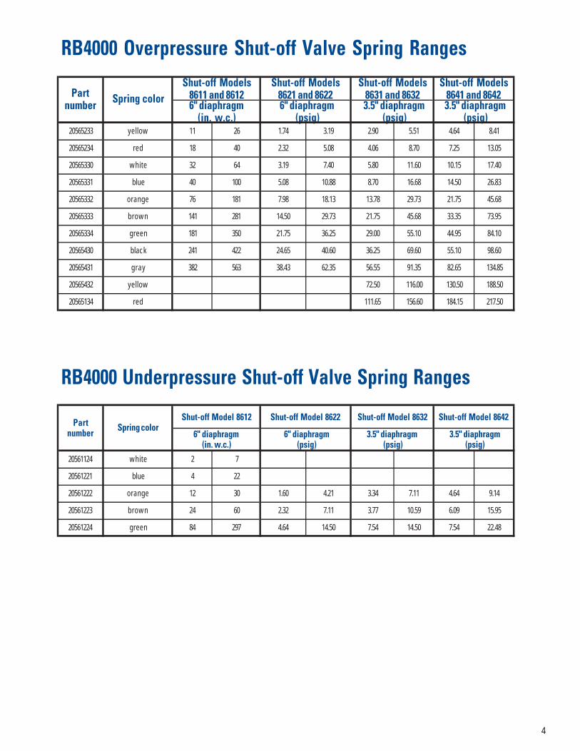
4
20565233 yellow 11 26 1.74 3.19 2.90 5.51 4.64 8.41
20565234 red 18 40 2.32 5.08 4.06 8.70 7.25 13.05
20565330 white 32 64 3.19 7.40 5.80 11.60 10.15 17.40
20565331 blue 40 100 5.08 10.88 8.70 16.68 14.50 26.83
20565332 orange 76 181 7.98 18.13 13.78 29.73 21.75 45.68
20565333 brown 141 281 14.50 29.73 21.75 45.68 33.35 73.95
20565334 green 181 350 21.75 36.25 29.00 55.10 44.95 84.10
20565430 black 241 422 24.65 40.60 36.25 69.60 55.10 98.60
20565431 gray 382 563 38.43 62.35 56.55 91.35 82.65 134.85
20565432 yellow 72.50 116.00 130.50 188.50
20565134 red 111.65 156.60 184.15 217.50
20561124 white 2 7
20561221 blue 4 22
20561222 orange 12 30 1.60 4.21 3.34 7.11 4.64 9.14
20561223 brown 24 60 2.32 7.11 3.77 10.59 6.09 15.95
20561224 green 84 297 4.64 14.50 7.54 14.50 7.54 22.48
6" diaphragm (psig)
3.5" diaphragm (psig)
RB4000 Underpressure Shut-off Valve Spring Ranges
RB4000 Overpressure Shut-off Valve Spring Ranges
6" diaphragm(in. w.c.)
6" diaphragm (psig)
Partnumber Spring color
Shut-off Models8611 and 8612
Shut-off Models8621 and 8622
Shut-off Models8631 and 8632
Shut-off Models8641 and 8642
6" diaphragm(in. w.c.)
3.5" diaphragm (psig)
3.5" diaphragm (psig)
3.5" diaphragm (psig)
Shut-off Model 8632 Shut-off Model 8642Partnumber Spring color
Shut-off Model 8612 Shut-off Model 8622

RB4000 Dimensions
Inches Without Built-in Shut-off Valve With Built-in Shut-off Valve
Valve Dimension RB4010 RB4020 RB4030-40 RB4011-12 RB4021-22 RB4031-32Body Size
A 10 10 10 10 10 10
B 22.2 21.3 21.3 22.2 21.3 21.3
C 3.9 3.9 3.9 3.9 3.9 3.9
2" D 18.9 14.2 14.2 18.9 14.2 14.2
E --- --- --- 12.0 12.0 10.9
F --- --- --- 5.9/3.5 5.9/3.5 5.9/3.5
G --- --- --- 5.7 5.7 5.7
Weight (lb) 90.4 63.9 72.8 105.8 77.2 86.0
A 11.7 11.7 11.7 11.7 11.7 11.7
B 28.0 25.8 24.6 28.0 25.8 24.6
C 5.1 5.1 5.1 5.1 5.1 5.1
3" D 23.6 18.9 14.2 23.6 18.9 14.2
E --- --- --- 14.3 14.3 13.1
F --- --- --- 5.9/3.5 5.9/3.5 5.9/3.5
G --- --- --- 7.3 7.3 7.3
Weight (lb) 154.3 123.5 108.0 178.6 147.7 132.3
Without Built-in Shut-off Valve With Built-in Shut-off Valve
5
Fig. 1 Fig. 2

The fluid from the upstream pipeenters the inlet chamber (8), passesthrough the opening in the valve seat(29) and (7), expands in the outletchamber (11) and then enters thedownstream pipe. The pressure of thegas is sensed downstream via thecontrol line, and passes through theport (13) before entering the controlchamber (14). This pressure exerts aforce on the surfaces of the diaphragm(15) that balances the calibrationspring (2) load for the ideal positioningof the valve plug (10) required toguarantee the requested flow anddownstream regulation.
If, during operation, the flowincreases due to a greater demand orthe upstream pressure decreases, thepressures in the chambers (11) and(14) immediately drop and thecalibration spring (2) moves thediaphragm unit (15), the stem (6) and
the valve plug (10) downwards,thereby modifying the adjustmentposition to give the required pressureand flow values.
The reverse action occurs wheneverthe flow decreases or if the upstreampressure increases. In this case, thepressure regulator’s adjustment unit isbalanced, and this permits theannulment of any negative forcescreated as a result of the change inthe pressure upstream in order toguarantee a constant outlet pressure.
At zero flowrate the regulatorguarantees full tightness in lock-up.
Shutoff Valve OperationThe shutoff valve is composed of thepressure switch for pressurecomparison (23), the control levers(24) and the shut off valve plug (25).
The shutoff valve is triggeredwhenever the pressure in the control
chamber (19) increases or decreasesbeyond the established values. This isachieved when the diaphragm unit(20) moves from the unbalancedposition and trip the control levers(24) to release the shutoff valve (25).Under the force generated by thespring (28), the shutoff valve (25) isbrought into contact with the valveseat (29) and immediately interruptsthe flow of gas.
Monitor application (See Page 10, Fig. 5)The monitor regulator interveneswhen ever the main active pressureregulator malfunctions (e.g. failsopen), and causes the downstreampressure to rise to the set pressure ofthe monitor regulator.
KeyNo. Description1 Spring chamber cover2 Calibration spring3 Diaphragm nut4 Diaphragm chamber bottom
case5 Balancing diaphragm6 Stem7 Valve orifice8 Inlet chamber9 Valve seat10 Valve plug11 Outlet chamber12 Balancing tube13 Control line intake14 Regulation control chamber15 Diaphragm16 Spring housing cover17 Spring adjustment lock nut18 Vent plug19 Shutoff valve diaphragm
chamber20 Diaphragm assembly21 Over pressure adjustment
spring22 Under pressure adjustment
spring23 Shutoff valve outlet chamber24 Control levers25 Shutoff valve plug26 By-pass27 Reset lever28 Shutoff valve spring29 Shutoff valve seat
RB4000 Operating Principle
6
Fig. 3
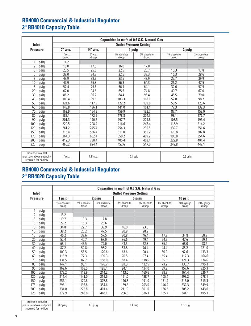
RB4000 Commercial & Industrial Regulator 2" RB4010 Capacity Table
Capacities in mcfh of 0.6 S.G. Natural GasInlet Outlet Pressure Setting
Pressure 7" w.c. 14" w.c. 1 psig 2 psig1" w.c. 2" w.c. 1% absolute 2% absolute 1% absolute 2% absolutedroop droop droop droop droop droop
1 psig 14.22 psig 18.0 17.5 16.0 17.03 psig 23.5 25.0 22.5 25.7 10.3 17.85 psig 38.0 34.3 32.5 38.3 16.3 28.68 psig 43.9 38.9 33.5 43.9 22.7 39.9
10 psig 47.9 55.8 56.3 64.3 26.2 47.515 psig 57.4 75.6 56.1 64.1 32.6 57.520 psig 67.0 94.8 65.5 74.8 40.7 67.030 psig 86.2 96.2 84.4 96.4 45.5 79.040 psig 105.4 99.6 103.3 118.0 52.8 98.250 psig 124.6 117.9 122.2 139.6 58.5 120.660 psig 143.8 136.1 141.0 161.1 77.3 139.370 psig 162.9 154.3 159.9 182.7 87.7 158.080 psig 182.1 172.5 178.8 204.3 98.1 176.790 psig 201.3 190.7 197.7 225.8 108.5 195.4
100 psig 220.5 208.9 216.6 247.4 118.9 214.2120 psig 261.2 245.4 254.3 290.5 139.7 251.6150 psig 316.4 566.4 311.0 355.2 170.8 307.8175 psig 364.3 652.4 358.2 409.2 196.8 354.6200 psig 412.3 738.4 405.4 463.1 222.8 401.4225 psig 460.2 824.4 452.6 517.0 248.8 448.1
Increase in outletpressure above set point 1" w.c. 1.5" w.c. 0.1 psig 0.2 psig
required for no flow
RB4000 Commercial & Industrial Regulator 2" RB4020 Capacity Table
Capacities in mcfh of 0.6 S.G. Natural GasInlet Outlet Pressure Setting
Pressure 1 psig 2 psig 5 psig 10 psig1% absolute 1% absolute 2% absolute 1% absolute 2% absolute 1% absolute 10% gauge 20% gauge
droop droop droop droop droop droop droop droop
1 psig2 psig 15.23 psig 19.7 10.3 17.85 psig 27.2 16.3 28.68 psig 34.8 22.7 39.9 16.0 23.6
10 psig 38.2 26.2 47.5 20.8 28.915 psig 46.2 32.6 57.5 30.8 46.4 17.8 34.8 50.820 psig 52.4 40.7 67.0 36.6 49.4 24.9 47.6 69.130 psig 68.1 45.5 79.0 43.5 62.8 35.9 68.0 98.240 psig 87.2 52.8 98.2 53.8 76.4 44.4 85.2 121.050 psig 100.3 58.5 120.6 63.6 90.4 50.0 92.6 133.360 psig 115.9 77.3 139.3 70.5 97.4 65.4 117.3 166.670 psig 131.5 87.7 158.0 83.4 118.5 65.5 121.3 174.680 psig 147.1 98.1 176.7 93.3 132.5 73.2 135.7 195.390 psig 162.6 108.5 195.4 94.4 134.0 89.9 157.6 225.3
100 psig 178.2 118.9 214.2 113.0 160.6 88.8 164.4 236.7120 psig 211.4 141.0 251.6 121.0 188.7 105.4 193.2 278.1150 psig 256.1 170.8 307.8 126.8 191.0 131.4 213.0 315.3175 psig 295.1 196.8 354.6 139.6 203.0 146.9 232.3 349.9200 psig 334.0 222.8 401.4 211.9 301.0 166.3 308.2 443.6225 psig 372.9 248.8 448.1 236.6 336.1 185.7 344.1 495.3
Increase in outletpressure above set point 0.2 psig 0.3 psig 0.3 psig 0.5 psig
required for no flow
7
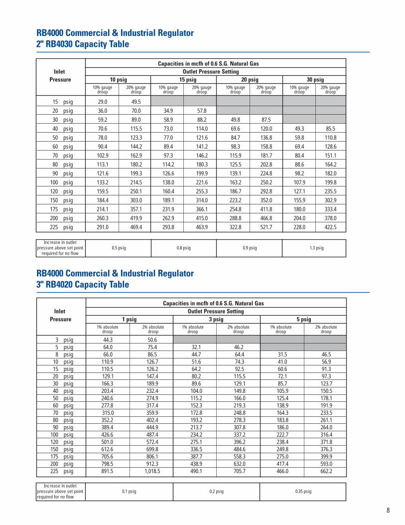
RB4000 Commercial & Industrial Regulator 2" RB4030 Capacity Table
RB4000 Commercial & Industrial Regulator 3" RB4020 Capacity Table
Capacities in mcfh of 0.6 S.G. Natural GasInlet Outlet Pressure Setting
Pressure 10 psig 15 psig 20 psig 30 psig10% gauge 20% gauge 10% gauge 20% gauge 10% gauge 20% gauge 10% gauge 20% gauge
droop droop droop droop droop droop droop droop
15 psig 29.0 49.520 psig 36.0 70.0 34.9 57.830 psig 59.2 89.0 58.9 88.2 49.8 87.540 psig 70.6 115.5 73.0 114.0 69.6 120.0 49.3 85.550 psig 78.0 123.3 77.0 121.6 84.7 136.8 59.8 110.860 psig 90.4 144.2 89.4 141.2 98.3 158.8 69.4 128.670 psig 102.9 162.9 97.3 146.2 115.9 181.7 80.4 151.180 psig 113.1 180.2 114.2 180.3 125.5 202.8 88.6 164.290 psig 121.6 199.3 126.6 199.9 139.1 224.8 98.2 182.0
100 psig 133.2 214.5 138.0 221.6 163.2 250.2 107.9 199.8120 psig 159.5 250.1 160.4 255.3 186.7 292.8 127.1 235.5150 psig 184.4 303.0 189.1 314.0 223.2 352.0 155.9 302.9175 psig 214.1 357.1 231.9 366.1 254.8 411.8 180.0 333.4200 psig 260.3 419.9 262.9 415.0 288.8 466.8 204.0 378.0225 psig 291.0 469.4 293.8 463.9 322.8 521.7 228.0 422.5
Increase in outletpressure above set point 0.5 psig 0.8 psig 0.9 psig 1.3 psig
required for no flow
Capacities in mcfh of 0.6 S.G. Natural GasInlet Outlet Pressure Setting
Pressure 1 psig 3 psig 5 psig1% absolute 2% absolute 1% absolute 2% absolute 1% absolute 2% absolute
droop droop droop droop droop droop
3 psig 44.3 50.6 5 psig 64.0 75.4 32.1 46.2 8 psig 66.0 86.5 44.7 64.4 31.5 46.5
10 psig 110.9 126.7 51.6 74.3 41.0 56.9 15 psig 110.5 126.2 64.2 92.5 60.6 91.3 20 psig 129.1 147.4 80.2 115.5 72.1 97.3 30 psig 166.3 189.9 89.6 129.1 85.7 123.7 40 psig 203.4 232.4 104.0 149.8 105.9 150.5 50 psig 240.6 274.9 115.2 166.0 125.4 178.1 60 psig 277.8 317.4 152.3 219.3 138.9 191.9 70 psig 315.0 359.9 172.8 248.8 164.3 233.5 80 psig 352.2 402.4 193.2 278.3 183.8 261.1 90 psig 389.4 444.9 213.7 307.8 186.0 264.0
100 psig 426.6 487.4 234.2 337.2 222.7 316.4 120 psig 501.0 572.4 275.1 396.2 238.4 371.8 150 psig 612.6 699.8 336.5 484.6 249.8 376.3 175 psig 705.6 806.1 387.7 558.3 275.0 399.9 200 psig 798.5 912.3 438.9 632.0 417.4 593.0 225 psig 891.5 1,018.5 490.1 705.7 466.0 662.2
Increase in outletpressure above set point 0.1 psig 0.2 psig 0.35 psigrequired for no flow
8

RB4000 Commercial & Industrial Regulator 3" RB4040 Capacity Table
Capacities in mcfh of 0.6 S.G. Natural GasInlet Outlet Pressure Setting
Pressure 10 psig 15 psig 20 psig 30 psig10% gauge 20% gauge 10% gauge 20% gauge 10% gauge 20% gauge 10% gauge 20% gauge
droop droop droop droop droop droop droop droop
15 psig 52.0 88.720 psig 67.4 131.0 63.3 104.830 psig 106.1 159.6 109.1 163.3 98.1 172.440 psig 132.1 216.2 132.3 206.6 137.1 236.4 97.1 168.450 psig 139.8 221.0 142.7 225.3 166.8 269.5 117.8 218.360 psig 169.2 269.9 162.1 255.9 193.6 312.9 136.7 253.370 psig 184.5 292.0 180.2 270.7 228.3 357.9 158.4 297.780 psig 211.7 337.2 207.0 326.8 247.2 399.5 174.6 323.590 psig 218.0 357.3 234.4 370.1 274.0 442.9 193.5 358.6
100 psig 249.3 401.4 250.1 401.6 321.5 492.9 212.5 393.7120 psig 285.9 448.4 297.0 472.8 367.8 576.8 250.3 463.9150 psig 345.1 567.1 342.7 569.1 439.7 693.4 307.2 596.7175 psig 383.8 640.2 429.4 677.9 501.9 811.2 354.5 656.9200 psig 487.2 785.8 476.4 752.1 569.0 919.5 401.8 744.6225 psig 521.7 841.4 544.1 859.0 636.0 1027.8 449.2 832.3
Increase in outletpressure above set point 0.6 psig 1.0 psig 1.1 psig 1.5 psig
required for no flow
RB4000 Commercial & Industrial Regulator 3" RB4030 Capacity Table
Capacities in mcfh of 0.6 S.G. Natural GasInlet Outlet Pressure Setting
Pressure 10 psig 15 psig10% gauge 20% gauge 10% gauge 20% gauge
droop droop droop droop
15 psig 57.1 97.520 psig 70.9 137.9 68.8 113.930 psig 116.6 175.3 116.0 173.840 psig 139.1 227.5 143.8 224.650 psig 153.7 242.9 151.8 239.660 psig 178.1 284.1 176.2 278.270 psig 202.7 320.9 191.7 288.080 psig 222.8 355.0 225.0 355.290 psig 239.6 392.6 249.4 393.7
100 psig 262.4 422.6 271.9 436.6120 psig 314.2 492.7 316.0 502.9150 psig 363.3 596.9 372.5 618.6175 psig 421.8 703.5 456.8 721.2200 psig 512.8 827.2 517.8 817.5225 psig 573.3 924.7 578.8 913.9
Increase in outletpressure above set point 0.5 psig 0.8 psig
required for no flow
9

Before installing the pressure regulator inthe piping, the following must be checked:• the upstream and downstream flanges
must be parallel and the pressureregulating unit must be capable of beingfitted without undue stress.
• the upstream piping must be cleanedfrom all impurities (sand, welding slag,etc.)
• the pressure regulator must not bevisibly damaged.
• the inlet and outlet chambers of thepressure regulator must be perfectlyclean.
After these checks have been made,the unit can be installed in the piping,making sure that the direction of gas flowcorresponds to the arrow on the pressureregulator’s body.
We recommend performing installationwith the valve body in horizontalalignment.
The following are also recommended:• A electrically insulating joint upstream
and downstream, if the incoming and
outgoing piping is made with ferrousmaterial.
• An ON/OFF valve upstream anddownstream of the pressure regulator.
• A manometer or pressure gaugeupstream and downstream from thepressure regulator.
• An upstream filter.• A relief valve downstream for start-up
and changes in pressure setting• A relief valve for accidental over-
pressure (example: the exposure of thedownstream piping to direct sunlight atzero flow).
• Free passage for maintenanceoperations
• If the case of an ON/OFF gas load, thedownstream volume must be grater thanft3 per 1000 ft3/hr. of flowrate.
All variations in diameter downstreammust be performed progressively in orderto prevent negative turbulence.
Avoid locating the control line piping:• Near sources of heat
• Direct sun light.
The pressure regulator’s control linemust be connected to the downstreampipe. These connections must be insertedin a straight section of the downstreampiping as indicated in the installationdiagrams (Figures 4, 5, 6).
For this purpose, we recommendwelding the control line connections onthe upper part of the piping in order toprevent impurities and condensate fromcollecting and obstructing the passage ofthe gas. It is also important to make surethat the control line piping slopes slightlydownwards to the pipe (Fig. 7). Foradequate operation, the gas velocity at thecontrol line position in the pipe, must notexceed those given below:
Low pressure < 2.9 psig: 50-65 ft/s
Med/high pressure> 2.9 psig: 65-130 ft/s
Key No. Description1 Upstream valve2 Differential pressure
gauge3 Strainer/Filter4 Upstream pressure gauge5 Regulator/Monitor6 Shutoff valve7 Pressure gauge8 Monitor Regulator9 Shutoff valve impulse10 Regulator impulse11 Monitor regulator impulse12 Downstream pressure
gauge13 Discharge vent pipe14 Downstream valve15 Upstream isolating
connection16 Discharge vent pipe17 Regulator vent18 Meter19 Peak shaving valve20 Downstream electrical
insulating connection
Installation
Diameter
Diameter
Diameter
Diameter
Diameter
Diameter
Diameter
Diameter
Diameter
Diam
eter
Diam
eter
Diam
eter
DiameterDiameter Diameter
Diameter
Diameter
Fig. 4
Fig. 5
Fig. 6
Fig. 7
10

Start-UpAfter the pressure regulator has beeninstalled, make sure that:• the on/off valve upstream (1) and
downstream (14) and the bleeder cock(13) are all closed ;
• the pressure of the inlet gas is nothigher than the established designvalue.
After these checks have been made,proceed as follows :• partially open the upstream on/off valve
(1) slowly just enough to make surethat a very small amount of gaspasses;
• reset the shutoff valve whenever it hasbeen set for minimum pressureintervention because it will be closed inthe absence of pressure (see theparagraph regarding the resetting of theshutoff unit);
• check that the pressure rises slowly onthe gauges (4) and (12); thedownstream pressure must stabilisearound the pre-set set value or a valueslightly higher (if the pressure continuesto rise, interrupt the starting procedureby closing the upstream on/off valve (1)and consult the trouble-shootingdiagram to identify the cause of themalfunction);
• after the upstream pressure value hasstabilised, open the on/off valve (1)completely;
• then slowly open the downstreamon/off valve (14) until the piping iscompletely filled.
At this point, the pressure regulator isoperative.
The same procedure must be usedwhen installing monitor-equippedpressure regulators connected on linewith the active pressure regulator (seeFig. 5), bearing in mind that the gauge(7) installed in the section in betweenthe two regulators must indicate thesame pressure value as the upstreamgauge (4).
Pressure Regulator Setting (Fig.3) The pressure regulator is usuallydelivered already set to the specificationsindicated in the order. Whenever the setpressure must be modified, this valuemust be set within the setting range of
the spring installed.After first checking the suitability of the
spring installed to achieve the desiredsetting value, proceed as follows:
• To increase the value of the setpressure:rotate the spring adjustment ferrule nut(17) clockwise using the adjustmentwrench until the desired value isreached (which can be read on thegauge downstream).
• To decrease the value of the setpressure:proceed as above, rotating the springadjustment ferrule counter-clockwise.
These operations can be performedregardless of whether the pressureregulator is delivering flow or thedownstream on/off cock is closed,making sure (in the latter case) to openthe discharge plug (13), downstream ofthe regulator. This valve should be closedafter the desired set pressure is obtained.
Shutoff Device SettingAfter first checking the suitability of thespring installed to achieve the desired setpressure, proceed as follows:Check the setting of the shutoff unit :
• To reach the maximum downstreampressure: Close the ON/OFF valve downstream14 (Fig.4) and slowly increase thepressure downstream until the desiredmaximum intervention pressure isreached. In order to correct this value,rotate the spring adjustment lock nut 21(Fig.3) clockwise to increase the setpressure and counter-clockwise todecrease the value.
• To reach the minimum downstreampressure:Close the upstream ON/OFF valve 1(Fig. 4), and slowly discharge thedownstream pressure until the desiredminimum intervention pressure isreached.
In order to correct this value, rotate thespring adjustment lock nut 22 (Fig.3)clockwise to increase the setting value,and counter-clockwise to decrease the
value.
IMPORTANT!The changing of the setting of theshutoff valve must always beperformed with the diaphragm controlchamber 19 (Fig. 3) under pressure.
Shutoff Device Reset (Fig.4, 5 & 6)The shutoff device must be reset onlyafter first identifying the reason why ittriggered in the first place. To restorenormal operating conditions the followingoperations should be performed.
• Close the ON/OFF valve downstream (14);
• Open the valve for the gauges4 and 12
• Downstream pressure = 0 (discharge any residual pressure byopening the cock 13).
• Relief valve and discharge valve closed
• Check the seal of the unit’s valve seatby opening the discharge valve (13)(test using bubble system):
- slowly rotate the reset lever 27 (Fig.3)clockwise until the internal bypass 26(Fig. 3) is opened. This operationpermits the filling of the outlet chamber(11), the piping downstream and thecontrol chamber 19 (Fig. 3) , which canbe checked on the gauge positioneddownstream ;
- after the pressure on the gauge hasstabilised, continue using the resetlever 27 (Fig.3) until it can beconnected to the control levers 24(Fig.3), and at this point, the reset leverwill remain stable in its open position.
After these operations have beenperformed, the shutoff valve will be readyfor service and the downstream valve(14) can be slowly reopened. Whenrestoring normal operating conditions, theshutoff valve must always be resetwhenever the valve is equipped with theminimum downstream pressureintervention function.
11

Trouble-Shooting
Anti-pumping valve (97)
Dirt
Insufficient downstream volume
Erroneus pressure impulse position
Compensation diaphragm (23)
Adjustment spring (5)
Diaphragm (10)
Erroneus pressure impulse position
Check setting
Replace
Check
Damaged
Incorrect assembly
Check
Check
Dirt
Erroneus pressure impulse position
Inadequate downstream piping
Anti-pumping valve (97)
Balancing diaphragm (23)
Diaphragm (10)
Adjustment spring (5)
Clean moving parts
Check
Check
Adjust or remplace internal parts
Replace
Replace
Check and replace if necessary
Hunting
Excessive tolerance setting between min & max operation levels
Slow response tochanges in flow
Check
Clean
Check
Check
Imperfect tightness
Downstream pressure beyond set value
Diaphragm damaged (109) Lever system deteriorated
Shutoff valve reset impossible
Damaged
Incorrect assembly
Valve seat (19)Out of alignment
Incorrect hardness
Check
Check
Check
Replace
Check
Replace
Foreign bodies on valve plug
Valve plug broken
O-ring (37) or (34) worn-out
Valve plug (19) worn-out
Dented valve seat (20)
Stem jammed by incrustation (24)
Valve plug fails to closeImperfect seal atregulator lock-up
Regulator fully open
Balancing diaphragm (23)
Diaphragm damaged (10)
Pressure impulse not connected
Pressure impulse broken
Erroneous assembly
Loosened
Loosened
Damaged
Crushed spring pack
Replace
Replace
Check
Check and clean
Clean
Replace
Replace
Check
Check
Check and fasten
Check and fasten
Replace
Replace
Replace
Setting above spring limits (5)
Imperfect diaphragm fastening (10)
Shutoff valve closedNo upstream pressure
Low upstreampressure
ReplaceDiaphragm damaged (10)
Pressure impulse not connected
Check filter Check and change cartridge
Check opening of upstream valve Check
Pressure impulse broken
Check
Replace
Insufficient caliberDemand higher than
regulator flow Check max regulator flow
Malfunction
Pressure BeyondRegulator Setting
No Flow
Low DownstreamPressure andFlow
12
13
Warranty
Actaris Metering Systems, 970 Highway 127 North, Owenton, Kentucky 40359-9802, warrants this gas productagainst defects in materials and workmanship for the earlier of one (1) year from the date the product is shippedby Actaris or a period of one year from the date the product is installed by Actaris at the original purchaser’s site.During such one-year period, provided that the original purchaser continues to own the product, Actaris will, atits sole option, repair any defects, replace the product or repay the purchase price.
This warranty will be void if the purchaser fails to observe the procedures for installation, operation or serviceof the product as set forth in the Operating Manual and Specifications for the product or if the defect is causedby tampering, physical abuse or misuse of the product. Actaris specifically disclaims all implied warrantiesincluding those of merchantability or of fitness for a particular purpose. Under no circumstances will Actaris beliable for incidental or consequential damages of any kind whatsoever.
Actaris’ liability for any claim of any kind, including negligence and breach of warranty for the sale and use ofany product covered by or furnished, shall in no case exceed the price allocable to the product or part thereofwhich gives rise to the claim.
In the event of a malfunction of the product, consult your Actaris Service Representative or Actaris MeteringSystems, 970 Highway 127 North, Owenton, Kentucky 40359-9802.

14

GA-0015.1-GB-6.02© Copyright 2002, Actaris U.S. Gas, Inc.
Istec CorporationTel : (973) 383-9888
Fax : (973) 383-9088www.istec-corp.com