rbc-rbc safe communication interface test …€¦ · ... c lass 1 rbc-rbc safe communication...
TRANSCRIPT

© This document has been developed and released by UNISIG
Subset-099 v1.0.0 RBC-RBC Safe Communication Interface - Test Specification Page 1/97
ERTMS/ETCS – CLASS 1
RBC-RBC Safe Communication Interface
Test Specification
REF : Subset-099
ISSUE: 1.0.0
DATE : 31-October-2008
Company Technical Approval Management approval
ALSTOM
ANSALDO
BOMBARDIER
INVENSYS
SIEMENS
THALES
© This document has been developed and released by UNISIG
Subset-099 v1.0.0 RBC-RBC Safe Communication Interface - Test Specification Page 2/97
1. MODIFICATION HISTORY Issue Number
Date Section Number Modification / Description Author
0.1.0::06-Feb-08 Final version from the Unisig WP for delivery to EEIG Users Group and ERA CG
MM
0.1.1:: 28-Oct-08 3.2 Comment from EEIG Users Group concerning references, to provide always date and version.
MM
1.0.0:: 31-Oct-08 Final version after Unisig WP check, for delivery to ERA.
MM

© This document has been developed and released by UNISIG
Subset-099 v1.0.0 RBC-RBC Safe Communication Interface - Test Specification Page 3/97
2. TABLE OF CONTENTS 1. MODIFICATION HISTORY................................................................................................................2
2. TABLE OF CONTENTS....................................................................................................................3
3. INTRODUCTION .............................................................................................................................5
3.1 Purpose ...........................................................................................................................5
3.2 References ......................................................................................................................5
3.3 Terms and definitions ......................................................................................................5
3.4 Abbreviations...................................................................................................................6
4. TEST STRATEGY...........................................................................................................................7
4.1 General............................................................................................................................7
4.2 Test Procedure ................................................................................................................7
4.3 Test definition ..................................................................................................................8
4.4 Test Reporting .................................................................................................................8
4.5 Test Architecture .............................................................................................................9
5. SAI TEST ...................................................................................................................................10
5.1 Overview of the SAI Test Procedure..............................................................................10
5.1.1 Introduction................................................................................................................10
5.1.2 Test strategy..............................................................................................................10
5.1.3 Functionality set of the SAI user ................................................................................10
5.1.4 SAI configuration parameters ....................................................................................11
5.2 Sequence Number Defence Technique .........................................................................11
5.2.1 List of SN Functional Tests ........................................................................................11
5.2.2 TEST 1: Connection and SN initialisation (connection requested by the PE) .............12
5.2.3 TEST 2: Connection and SN initialisation (connection requested to the PE)..............16
5.2.4 TEST 3: SN incrementation in reception ....................................................................20
5.2.5 TEST 4: SN incrementation in transmission...............................................................22
5.3 Execution Cycle Defence Technique .............................................................................24
5.3.1 List of EC Functional Tests ........................................................................................24
5.3.2 TEST 5: Initialisation procedure performed by the PE................................................25
5.3.3 TEST 6: Initialisation procedure performed by the EUT .............................................26
5.3.4 TEST 7: EC incrementation in reception ....................................................................28
5.3.5 TEST 8: EC incrementation in transmission...............................................................30
5.3.6 TEST 9: Procedure for transmission delay detection initiated by the PE....................32
5.3.7 TEST 10: Procedure for transmission delay detection initiated by the EUT ...............34
5.4 Triple time stamping defence technique ........................................................................37
5.4.1 List of TTS Functional Tests ......................................................................................37
© This document has been developed and released by UNISIG
Subset-099 v1.0.0 RBC-RBC Safe Communication Interface - Test Specification Page 4/97
5.4.2 TEST 11: Clock offset estimation performed by the EUT...........................................38
5.4.3 TEST 12: Clock offset estimation performed by the PE .............................................41
5.4.4 TEST 13: Exchange of application data .....................................................................43
5.4.5 TEST 14: Initiation of clock offset estimation update procedure.................................44
5.4.6 TEST 15: Clock offset update procedure initiated by the PE......................................47
6. ALE TEST ..................................................................................................................................48
6.1 Functionality set of the ALE user ...................................................................................48
6.2 Configuration parameters ..............................................................................................48
6.2.1 TCP/IP configuration parameters...............................................................................48
6.2.2 ALE configuration parameters....................................................................................48
6.3 List of functional tests for Class D..................................................................................48
6.3.1.......................................................................................................................................48
6.4 List of functional tests for Class A (optional) ..................................................................49
6.5 Class D Tests ................................................................................................................50
6.5.1 Test_ALE 1: ALEPKTs correctly formed ....................................................................50
6.5.2 Test 2: Establish Class D connection.........................................................................56
6.5.3 Test 3: Data Transfer over a Class D connection.......................................................61
6.5.4 Test 4: Release of a Class D connection ...................................................................64
6.5.5 Test 5: Redundancy Management of a Class D connection.......................................69
6.6 Class A Tests (optional).................................................................................................72
6.6.1 Test_ALE_6: ALEPKTs correctly formed ...................................................................72
6.6.2 Test_ALE_7: Establish Class A connection ...............................................................80
6.6.3 Test_ALE_8: Data Transfer over a Class A connection .............................................84
6.6.4 Test_ALE_9: Release of a Class A connection..........................................................88
6.6.5 Test_ALE_10: Redundancy Management of a Class A connection ...........................93

© This document has been developed and released by UNISIG
Subset-099 v1.0.0 RBC-RBC Safe Communication Interface - Test Specification Page 5/97
3. INTRODUCTION
3.1 PURPOSE
3.1.1.1.1 This document specifies the general methodology and strategy for testing of the RBC-RBC Safe Communication Interface.
3.1.1.1.2 The objective of this specification is to check whether different implementations of the RBC-RBC Safe Communication Interface are able to interwork.
3.1.1.1.3 It is applicable to RBC-RBC safe communication interface providing communication services for safety-related applications.
3.1.1.1.4 The required test cases are specified in Parts 5 and 6 of this specification.
3.2 REFERENCES
3.2.1.1.1 This specification incorporates provisions from other publications by means of dated or undated references. The normative references are cited in the text in the appropriate places, the publications are listed hereafter. As to dated references, subsequent amendments to or revisions of any of these publications apply to this architecture specification only when incorporated by amendment or revision. For undated references, the latest edition of the publication referred to applies.
Name Date Description EN 50159-1 03.01 Safety-Related Communication in Closed Transmission
Systems EN 50159-2 03.01 Safety-Related Communication in Open Transmission
Systems Subset-026 02.06 ETCS/ERTMS Class 1; System Requirements Specification,
v2.3.0 Subset-037 10.05 Euroradio FIS, v2.3.0 Subset-092-2 02.06 Euroradio Test Cases, v.2.3.0 Subset-097 06.05 RBC-RBC Safe Communication Interface; Requirements,
v1.1.0 Subset-098 05.07 RBC-RBC Safe Communication Interface, v 1.0.0 Subset-108 06.06 ETCS/ERTMS Class 1; Interoperability consolidation on TSI
annex A documents, v 1.1.0
3.3 TERMS AND DEFINITIONS The definitions of the standards EN 50159-1,EN 50159-2 and [Subset-098] are used in this document.
© This document has been developed and released by UNISIG
Subset-099 v1.0.0 RBC-RBC Safe Communication Interface - Test Specification Page 6/97
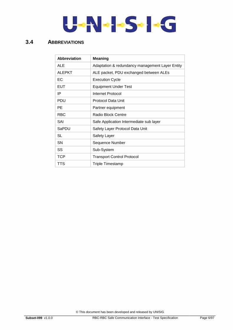
3.4 ABBREVIATIONS
Abbreviation Meaning
ALE Adaptation & redundancy management Layer Entity
ALEPKT ALE packet, PDU exchanged between ALEs
EC Execution Cycle
EUT Equipment Under Test
IP Internet Protocol
PDU Protocol Data Unit
PE Partner equipment
RBC Radio Block Centre
SAI Safe Application Intermediate sub layer
SaPDU Safety Layer Protocol Data Unit
SL Safety Layer
SN Sequence Number
SS Sub-System
TCP Transport Control Protocol
TTS Triple Timestamp

© This document has been developed and released by UNISIG
Subset-099 v1.0.0 RBC-RBC Safe Communication Interface - Test Specification Page 7/97
4. TEST STRATEGY
4.1 GENERAL
4.1.1.1.1 The test specification defines only test cases that are needed to prove interworking between two implementations of the RBC-RBC Safe Communication Interface.
4.1.1.1.2 Interworking means that two implementations are able to successfully exchange PDUs via the transmission system. This requires:
• to establish, maintain and release a safe connection;
• to agree the relevant configuration parameters between the peers;;
• to exchange data and manage messages;
• to handle the implemented defence techniques.
4.1.1.1.3 The purpose for tests on interworking are:
• to check the correct responses on PDUs of the peer implementation;
• to check the correct response in case of protocol errors and failures.
4.1.1.1.4 Tests of specific error cases that shall be performed are listed in parts 5 and 6 of this specification.
4.1.1.1.5 Since the real protocol implementations are used, the only degraded tests that can be carried out are those which can be performed without the use of a internal error generator. For example, tests are run on the reaction of the subsystems in the case of connection loss, while it is impossible to verify the reaction of real systems in the case of reception of the wrong sequence code.
4.1.1.1.6 The complete coverage of all the characteristics and aspects of the SAI protocol is beyond the aim of the current test specification. This type of coverage has to be ensured by the activities of the Compliance Test, which has to be carried out independently by each company, using specific Protocol Stack Simulators with the capability of generating errors.
4.1.1.1.7 No testing of features or functions that are ‘local matters’ is intended.
4.1.1.1.8 The functionality sets that an implementation must be able to manage are defined in parts 5 and 6 of this specification.
4.1.1.1.9 It assumend that the Euroradio Safety Layer has been tested according to Subset-092-2 on both sides.
4.2 TEST PROCEDURE
4.2.1.1.1 These tests are performed using two real equipments. The type of connection between the two implementations depends on the type of physical ports available on the real equipment. The equipments will be referred to as equipment under test (EUT) and partner equipment (PE):
© This document has been developed and released by UNISIG
Subset-099 v1.0.0 RBC-RBC Safe Communication Interface - Test Specification Page 8/97
this naming does not have any link with the role (initiator or responder) played by each equipment in the test.
4.3 TEST DEFINITION
4.3.1.1.1 For each test, the following parameters are specified:
a) Identification of Test Case: a unique Test Case Identifier and Title;
b) Configuration Data: each Test Case has to specify explicitly the configuration data that is relevant for its execution, to permit evaluation of the influence on functions caused by varying each set of configuration data;
c) Traceability: to allow traceability with respect to the communication protocol stack specification documents;
d) Testing Steps: list of steps to be performed to realise the whole Test Case;
e) Expected Results: Test Cases will be implemented in order to validate the correct operation of a EUT against particular test criteria. Test Specifications include also the verification of correct operation of a EUT as designed for nominal or degraded conditions.
4.3.1.1.2 Testing is described in four steps:
a) initial conditions: state of the equipment before performing the test;
b) preliminary steps: the set of actions to perform in order to begin the test;
c) test initiator: the list of actions that have to be performed to set the RBC-RBC connection in the state that allows the test execution;
d) expected results and verifications: definition of the expected results and the method of controlling the test run.
4.3.1.1.3 This method of describing the tests is used as a default for all test descriptions for tests and sub-tests throughout this document.
4.4 TEST REPORTING
4.4.1.1.1 For test reporting, a test form must been written, containing at least the following information:
a) reference to this test specification document;
b) the identifier of the test;
c) the result of the test;
d) any miscellaneous information such as date and tester identity.
© This document has been developed and released by UNISIG
Subset-099 v1.0.0 RBC-RBC Safe Communication Interface - Test Specification Page 9/97
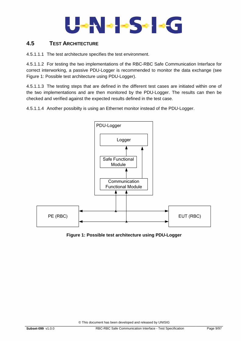
4.5 TEST ARCHITECTURE
4.5.1.1.1 The test architecture specifies the test environment.
4.5.1.1.2 For testing the two implementations of the RBC-RBC Safe Communication Interface for correct interworking, a passive PDU-Logger is recommended to monitor the data exchange (see Figure 1: Possible test architecture using PDU-Logger).
4.5.1.1.3 The testing steps that are defined in the different test cases are initiated within one of the two implementations and are then monitored by the PDU-Logger. The results can then be checked and verified against the expected results defined in the test case.
4.5.1.1.4 Another possibilty is using an Ethernet monitor instead of the PDU-Logger.
PE (RBC) EUT (RBC)
PDU-Logger
Communication
Functional Module
Safe Functional
Module
Logger
Figure 1: Possible test architecture using PDU-Logg er

© This document has been developed and released by UNISIG
Subset-099 v1.0.0 RBC-RBC Safe Communication Interface - Test Specification Page 10/97
5. SAI TEST
5.1 OVERVIEW OF THE SAI TEST PROCEDURE
5.1.1 INTRODUCTION
5.1.1.1.1 The Safe Application Interface specifies three defence techniques (see Subset-098):
a) Sequence numbering defence technique;
b) The Triple Time Stamping;
c) The Execution Cycle.
5.1.1.1.2 This section is divided into three sub-sections, one related to the Sequence Number defence technique, the second related to the Execution Cycle defence technique and the last related to the Triple Time Stamp defence technique. The tests related to the initialisation of the connection and data transfer between SAI layers are specified in the section related to the Sequence Number defence technique.
5.1.2 TEST STRATEGY
5.1.2.1.1 The following table provides a list of the safety defences that have to be tested internally by each company. This list is not exhaustive and some additional test cases could be requested depending on the protocol implementation.
Safety defence Reference
Message deletion (detected by SN) Subset-098
Message resequencing (detected by SN) Subset-098
Message repetition (detected by SN) Subset-098
Non valid message type Subset-098
Delayed messages during initialisation procedures Subset-098
Delayed application messages Subset-098
Message masquerade Subset-092-2
Message corruption Subset-092-2
Message insertion Subset 092-2
Table 1: Safety defences to be tested internally
5.1.3 FUNCTIONALITY SET OF THE SAI USER
5.1.3.1.1 The SAI user implements at least the following functions:
© This document has been developed and released by UNISIG
Subset-099 v1.0.0 RBC-RBC Safe Communication Interface - Test Specification Page 11/97
a) Connection management: initiate a connection at the SAI level;
b) Connection management: transmission of application data;
c) Connection management: reception of application data.
5.1.3.1.2 The implementation of these functions is a local matter.
5.1.4 SAI CONFIGURATION PARAMETERS
5.1.4.1.1 The SAI configuration parameters are defined in Subset-098.
5.1.4.1.2 These parameters should to be fixed using the guideline defined in Subset-098.
5.2 SEQUENCE NUMBER DEFENCE TECHNIQUE
5.2.1 LIST OF SN FUNCTIONAL TESTS
5.2.1.1.1 Test 1: connection and SN initialisation (connection requested by the peer entity). - this test checks that the EUT is able to accept an initialisation of the connection between SAI layers using a random initial sequence number.
5.2.1.1.2 Test 2: connection and SN initialisation (connection requested to the peer entity). - this test checks that the EUT is able to request an initialisation of the connection between SAI layers (including the initialisation of the sequence number).
5.2.1.1.3 TEST 3: SN incrementation in reception. - this test checks that the EUT accepts, in reception, a nominal incrementation of the SN.
5.2.1.1.4 TEST 4: SN incrementation in transmission. - this test checks that the EUT increments the SN, in transmission, in accordance with the test specification.

© This document has been developed and released by UNISIG
Subset-099 v1.0.0 RBC-RBC Safe Communication Interface - Test Specification Page 12/97
5.2.2 TEST 1: CONNECTION AND SN INITIALISATION (CONNECTION REQUESTED BY THE PE)
5.2.2.1 Test overview
5.2.2.1.1 The current test must check that the EUT is able to accept a connection request at the SAI level and accept a random initialisation of the SN.
5.2.2.1.2 The following figure describes the initialisation procedure:
AU1 SaPDU
AU2 SaPDU
Sa-Data. Indication
Responder (EUT) Initiator (PE)
Sa-Data. Request
Sa-Data. Indication
Sa-Data. Request
E
U
R
O
R
A
D I O
E UR O R A D I O
S A I
S A I
Sa-Connect. Request
Sa-Connect. Confirm
AU3 SaPDU
AR SaPDU
DT SaPDU (ExecutionCycleStart or OffsetAnsw1 message)
DT SaPDU (ElxecutionCycleStart or OffsetStart message )
Sa-Connect. Indication
Sa-Connect. Response Set Timer
Stop Timer
Set Timer
Stop Timer
DT SaPDU (First Appl. or
OffsetAnsw2 message)
Figure 2: Initialisation procedure
5.2.2.1.3 The following purposes must be checked:
a) at the reception of the Sa-Connect indication, the connection must be established at the SAI level and the SAI of the EUT produces the Sa-Connect Response: Subtest 1.1.
b) at the reception of the first Sa-Data indication (ExecutionCycleStart or OffsetStart message), the SAI of the EUT must answer with a Sa-Data Request message, (including the ExecutionCycleStart or OffsetAnsw1 message), start the Tsyn timer and accept a random initial sequence number: Subtest 1.2.

© This document has been developed and released by UNISIG
Subset-099 v1.0.0 RBC-RBC Safe Communication Interface - Test Specification Page 13/97
c) at the reception of the first application message (EC) or OffsetAnsw2 message (TTS), the SAI of the EUT must stop the Tsyn timer: Subtest 1.3.
5.2.2.2 Traceability with Subset-098
5.2.2.2.1 The initialisation procedure is defined in Subset-098, § 5.4.5.1.
5.2.2.2.2 The sequence number format and initialisation requirements are defined in Subset-098, § 5.4.4 and 5.4.7.
5.2.2.2.3 The format of the initialisation messages is defined in Subset-098, § 5.4.8.4 and 5.4.9.3.8.
5.2.2.3 SUB-TEST 1.1: TEST_SAI_1-1
5.2.2.3.1 The target of subtest 1.1. is to check that, at the reception of the sa-Connect indication, the SAI:
a) Considers the connection is established;
b) Answers by producing the Sa-Connect Response.
Test identifier TEST_SAI_1-1
Initial conditions No connection between the RBC’s
Preliminary steps 1. Establishment of the connection at the TCP/IP level.
2. Establishment of the connection at the ALE level.
3. Exchange of the AU1 SaPDU and AU2 SaPDU messages between SL Euroradio layers.
Test initiator Reception of the AU3 SaPDU by the EUT SL Euroradio. The SL Euroradio must “send” a Sa-Connect Indication to the SAI
Expected result 1: The EUT Responding SAI must answer with a “Sa-connect Response”.
Verification :reception by the EUT Ini SL Euroradio of “Sa-Connect Confirm” from the PE.
Expected results and verifications
Expected result 2: The EUT SAI must consider that the connection is open at the SAI level with the peer entity.
Verification :Exchange of data is possible.
Table 2: TEST_SAI_1-1
5.2.2.4 SUB-TEST 1.2: TEST_SAI_1-2
© This document has been developed and released by UNISIG
Subset-099 v1.0.0 RBC-RBC Safe Communication Interface - Test Specification Page 14/97
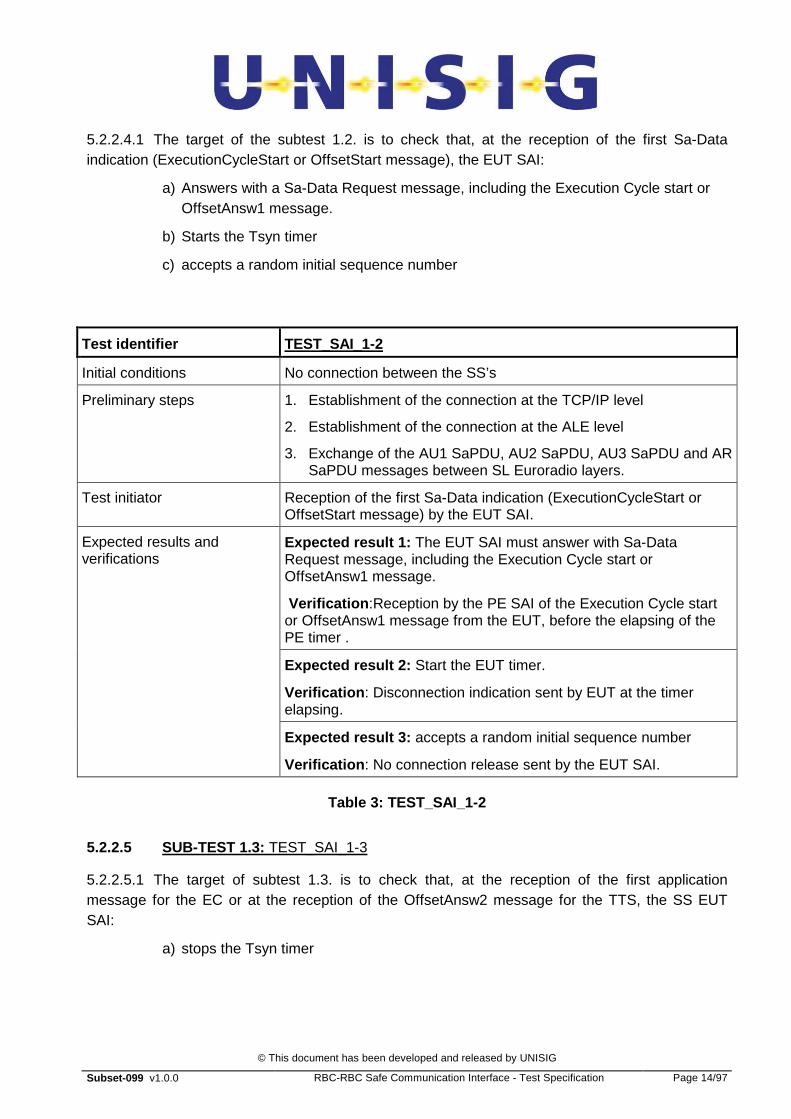
5.2.2.4.1 The target of the subtest 1.2. is to check that, at the reception of the first Sa-Data indication (ExecutionCycleStart or OffsetStart message), the EUT SAI:
a) Answers with a Sa-Data Request message, including the Execution Cycle start or OffsetAnsw1 message.
b) Starts the Tsyn timer
c) accepts a random initial sequence number
Test identifier TEST_SAI_1-2
Initial conditions No connection between the SS’s
Preliminary steps 1. Establishment of the connection at the TCP/IP level
2. Establishment of the connection at the ALE level
3. Exchange of the AU1 SaPDU, AU2 SaPDU, AU3 SaPDU and AR SaPDU messages between SL Euroradio layers.
Test initiator Reception of the first Sa-Data indication (ExecutionCycleStart or OffsetStart message) by the EUT SAI.
Expected result 1: The EUT SAI must answer with Sa-Data Request message, including the Execution Cycle start or OffsetAnsw1 message.
Verification :Reception by the PE SAI of the Execution Cycle start or OffsetAnsw1 message from the EUT, before the elapsing of the PE timer .
Expected result 2: Start the EUT timer.
Verification : Disconnection indication sent by EUT at the timer elapsing.
Expected results and verifications
Expected result 3: accepts a random initial sequence number
Verification : No connection release sent by the EUT SAI.
Table 3: TEST_SAI_1-2
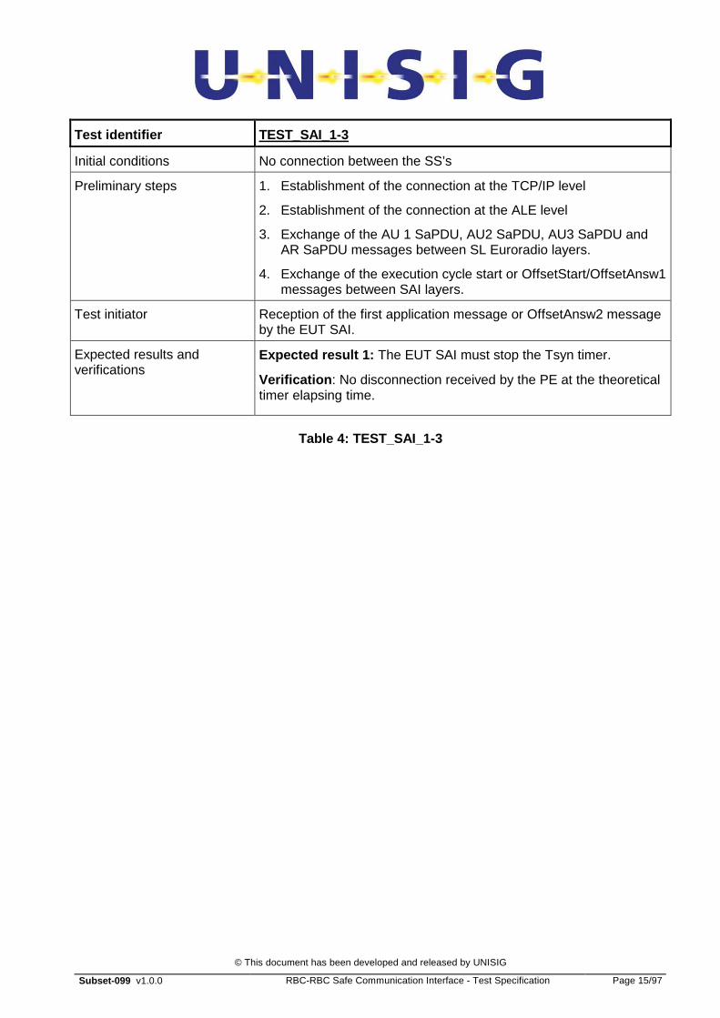
5.2.2.5 SUB-TEST 1.3: TEST_SAI_1-3
5.2.2.5.1 The target of subtest 1.3. is to check that, at the reception of the first application message for the EC or at the reception of the OffsetAnsw2 message for the TTS, the SS EUT SAI:
a) stops the Tsyn timer
© This document has been developed and released by UNISIG
Subset-099 v1.0.0 RBC-RBC Safe Communication Interface - Test Specification Page 15/97
Test identifier TEST_SAI_1-3
Initial conditions No connection between the SS’s
Preliminary steps 1. Establishment of the connection at the TCP/IP level
2. Establishment of the connection at the ALE level
3. Exchange of the AU 1 SaPDU, AU2 SaPDU, AU3 SaPDU and AR SaPDU messages between SL Euroradio layers.
4. Exchange of the execution cycle start or OffsetStart/OffsetAnsw1 messages between SAI layers.
Test initiator Reception of the first application message or OffsetAnsw2 message by the EUT SAI.
Expected results and verifications
Expected result 1: The EUT SAI must stop the Tsyn timer.
Verification : No disconnection received by the PE at the theoretical timer elapsing time.
Table 4: TEST_SAI_1-3
© This document has been developed and released by UNISIG
Subset-099 v1.0.0 RBC-RBC Safe Communication Interface - Test Specification Page 16/97
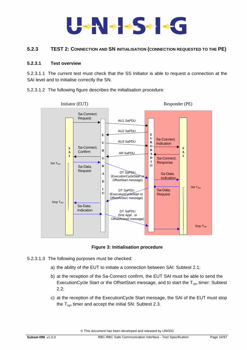
5.2.3 TEST 2: CONNECTION AND SN INITIALISATION (CONNECTION REQUESTED TO THE PE)
5.2.3.1 Test overview
5.2.3.1.1 The current test must check that the SS Initiator is able to request a connection at the SAI level and to initialise correctly the SN.
5.2.3.1.2 The following figure describes the initialisation procedure:
AU1 SaPDU
AU2 SaPDU
Sa-Data. Indication
Responder (PE) Initiator (EUT)
Sa-Data. Request
Sa-Data. Indication
Sa-Data. Request
E
U
R
O
R
A
D I O
E UR O R A D I O
S A I
S A I
Sa-Connect. Request
Sa-Connect. Confirm
AU3 SaPDU
AR SaPDU
DT SaPDU (ExecutionCycleStart or OffsetAnsw1 message)
DT SaPDU (ExecutionCycleStart or OffsetStart message)
Sa-Connect. Indication
Sa-Connect. Response Set TSyn
Stop TSyn
Set TSyn
DT SaPDU (first Appl . or
OffsetAnsw2 message)
Stop TSyn
Figure 3: Initialisation procedure
5.2.3.1.3 The following purposes must be checked:
a) the ability of the EUT to initiate a connection between SAI: Subtest 2.1;
b) at the reception of the Sa-Connect confirm, the EUT SAI must be able to send the ExecutionCycle Start or the OffsetStart message, and to start the Tsyn timer: Subtest 2.2;
c) at the reception of the ExecutionCycle Start message, the SAI of the EUT must stop the Tsyn timer and accept the initial SN: Subtest 2.3.

© This document has been developed and released by UNISIG
Subset-099 v1.0.0 RBC-RBC Safe Communication Interface - Test Specification Page 17/97
5.2.3.2 Traceability with Subset-098
5.2.3.2.1 The initialisation procedure is defined in Subset-098, § 5.4.5.1.
5.2.3.2.2 The sequence number format and initialisation requirements are defined in Subset-098, § 5.4.4 and 5.4.7.
5.2.3.2.3 The format of the initialisation message (ExecutionCycle Start or OffsetStart) is defined in Subset-098, § 5.4.8.4 and 5.4.9.3.8.
5.2.3.3 SUB-TEST 2.1: TEST_SAI_2-1
5.2.3.3.1 The target of subtest 2.1. is to check that the SS Initiator is able to initiate a connection at the SAI level.
Test identifier TEST_SAI_2-1
Initial conditions No connection between the RBC’s
Test initiator Request of a connection by the EUT SAI User.
The tested SAI must send a Sa-Connect request to the EUTSL Euroradio.
Intermediate steps The connection must be established at the TCP/IP, ALE and SL Euroradio level between the two devices.
Expected results and verifications
Expected result 1: At the reception of the “Sa-Connect confirm” from the SL Euroradio, the EUT SAI considers that the safe connection is established with the peer SAI.
Verification : Implicitly by the performing of the following tests.
Table 5: TEST_SAI_2-1
5.2.3.4 SUB-TEST 2.2: TEST_SAI_2-2
5.2.3.4.1 The target of subtest 2.2 is to check that, at the reception of the Sa-Connect confirm, the EUT SAI:
a) answers sending the ExecutionCycle or OffsetStart message;
b) starts the EUT timer (Tsyn). There is no requirement on the SN initialisation - the value can be fixed or randomly chosen.
Test identifier TEST_SAI_2-2

© This document has been developed and released by UNISIG
Subset-099 v1.0.0 RBC-RBC Safe Communication Interface - Test Specification Page 18/97
Initial conditions No connection between the RBC’s
Preliminary steps 1. Establishment of the connection at the TCP/IP level
2. Establishment of the connection at the ALE level
3. Establishment of the connection at the SAI level (ended at the “Sa-Connect confirm” reception)
Test initiator Reception of “Sa-Connect confirm” by the EUT SAI.
Expected result 1: Send the “ExecutionCycle Start” or “OffsetStart” message to the PE with the initial sequence number.
Verification : Reception by the PE of the “ExecutionCycle Start” message
Expected results and verifications
Expected result 2: Start the EUT timer.
Verification : Disconnection indication sent by EUT at the timer elapsing.
Table 6: TEST_SAI_2-2
5.2.3.5 SUB-TEST 2.3: TEST_SAI_2-3
5.2.3.5.1 The target of subtest 2.3. is to check that, at the reception of the ExecutionCycle Start or OffsetAnsw1 message, the EUT SAI:
a) stops the Tsyn timer;
b) accept the initial SN.
Test identifier TEST_SAI_2-3
Initial conditions No connection between the RBC’s
Preliminary steps 1. Establishment of the connection at the TCP/IP level
2. Establishment of the connection at the ALE level
3. Establishment of the connection at the SAI level
4. Transmission of the “ExecutionCycle Start” or “OffsetStart” message to the peer entity (SS Resp).
Test initiator Reception of the “ExecutionCycle Start” or “OffsetAnsw1” message from the PE SS.
Expected results and verifications
Expected result 1: The EUT SAI must stop the Tsyn timer.
Verification : No disconnection received by the EUT at the theoretical timer elapsing time.
© This document has been developed and released by UNISIG
Subset-099 v1.0.0 RBC-RBC Safe Communication Interface - Test Specification Page 19/97
Expected result 2: Accept the initial SN.
Verification : Check the next message is sent to the PE SAI.
Table 7: TEST_SAI_2-3

© This document has been developed and released by UNISIG
Subset-099 v1.0.0 RBC-RBC Safe Communication Interface - Test Specification Page 20/97
5.2.4 TEST 3: SN INCREMENTATION IN RECEPTION
5.2.4.1 Test overview
5.2.4.1.1 The current test must check that the RBC properly processes the SN incrementation in reception. This test does not include zero crossing. The check of zero crossing could be performed in a reasonable time only if it is possible to force the initialisation value used for the sequence number.
5.2.4.1.2 The following figure describes the test procedure:
SS1 (PE
)
SS2 (EU
T)
Message SS1 to SS2 #X
Message SS1 to SS2 #X+1
Message SS1 to SS2 #X+6
TIM
E
Message SS1 to SS2 #X+3 Message SS1 to SS2 #X+4
Message SS1 to SS2 #X+5
Message SS1 to SS2 #X+2
Note : Only the messages from the SS1 to SS2 are indicated
Figure 4: SN incrementation in reception
5.2.4.1.3 The initial value of the SN must be low enough to enable the test of the SN on a sufficient number of messages (e.g. initial SN << 64535).
5.2.4.2 Traceability with the Subset 098
5.2.4.2.1 SN incrementation is described in Subset-098, § 5.4.7.
5.2.4.3 TEST 3: TEST_SAI_3
5.2.4.3.1 The target of test 3 is to check that the SS processes incrementation of the received SN in the right way.
Test identifier TEST_SAI_3
Initial conditions No connection between the RBC’s
© This document has been developed and released by UNISIG
Subset-099 v1.0.0 RBC-RBC Safe Communication Interface - Test Specification Page 21/97
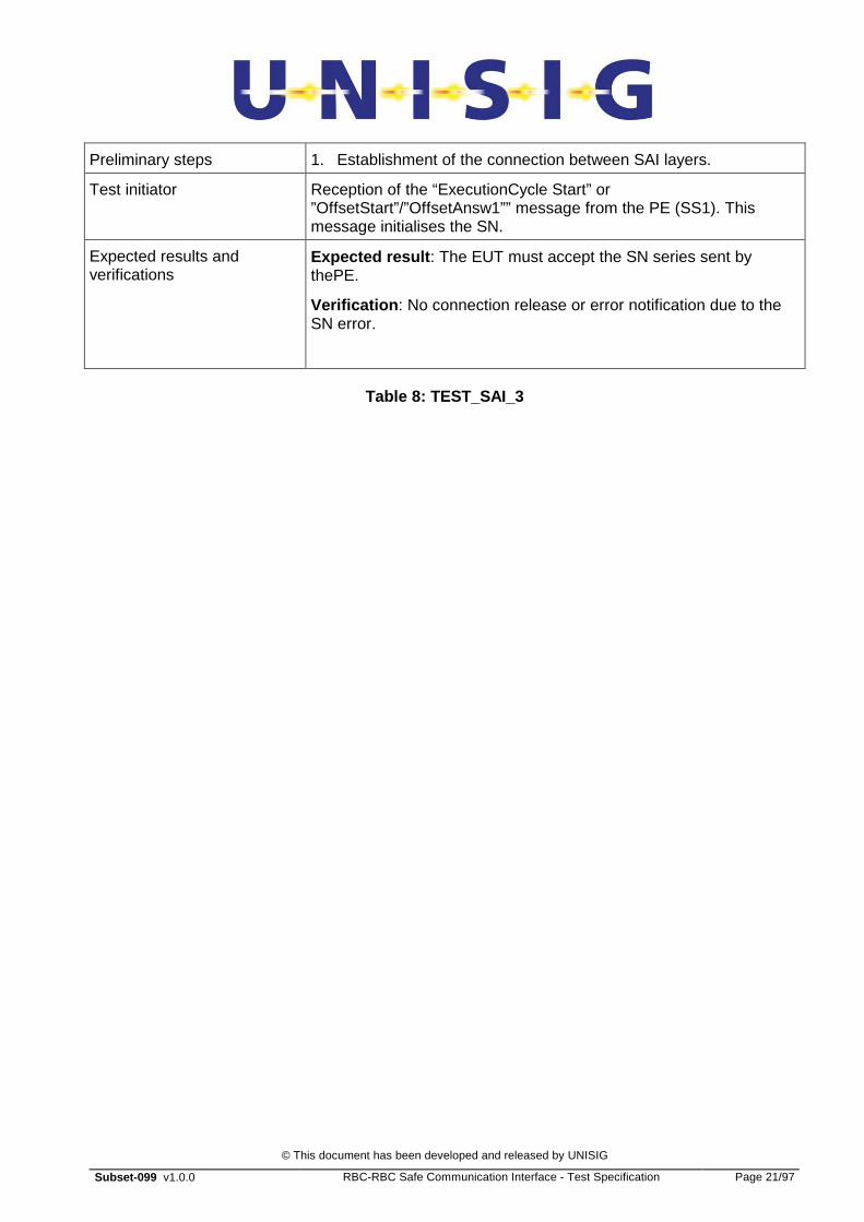
Preliminary steps 1. Establishment of the connection between SAI layers.
Test initiator Reception of the “ExecutionCycle Start” or ”OffsetStart”/”OffsetAnsw1”” message from the PE (SS1). This message initialises the SN.
Expected results and verifications
Expected result : The EUT must accept the SN series sent by thePE.
Verification : No connection release or error notification due to the SN error.
Table 8: TEST_SAI_3
© This document has been developed and released by UNISIG
Subset-099 v1.0.0 RBC-RBC Safe Communication Interface - Test Specification Page 22/97
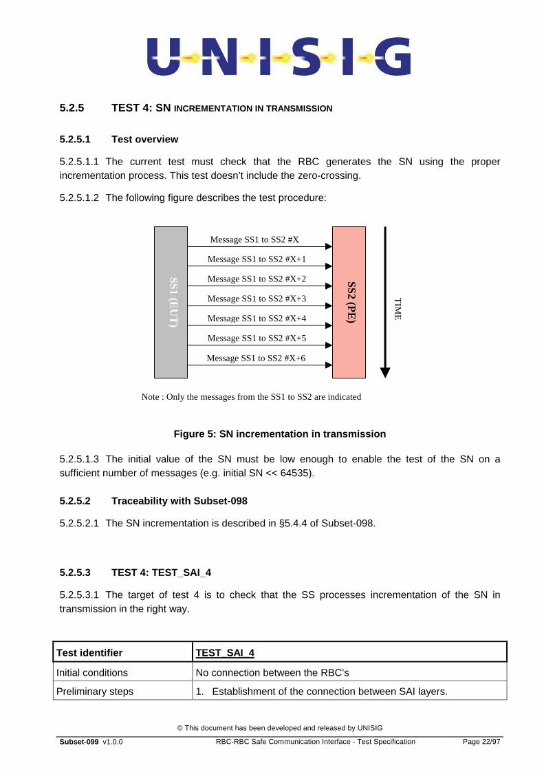
5.2.5 TEST 4: SN INCREMENTATION IN TRANSMISSION
5.2.5.1 Test overview
5.2.5.1.1 The current test must check that the RBC generates the SN using the proper incrementation process. This test doesn’t include the zero-crossing.
5.2.5.1.2 The following figure describes the test procedure:
SS1 (EU
T)
SS2 (PE
)
Message SS1 to SS2 #X
Message SS1 to SS2 #X+1
Message SS1 to SS2 #X+6
TIM
E
Message SS1 to SS2 #X+3 Message SS1 to SS2 #X+4
Message SS1 to SS2 #X+5
Message SS1 to SS2 #X+2
Note : Only the messages from the SS1 to SS2 are indicated
Figure 5: SN incrementation in transmission
5.2.5.1.3 The initial value of the SN must be low enough to enable the test of the SN on a sufficient number of messages (e.g. initial SN << 64535).
5.2.5.2 Traceability with Subset-098
5.2.5.2.1 The SN incrementation is described in §5.4.4 of Subset-098.
5.2.5.3 TEST 4: TEST_SAI_4
5.2.5.3.1 The target of test 4 is to check that the SS processes incrementation of the SN in transmission in the right way.
Test identifier TEST_SAI_4
Initial conditions No connection between the RBC’s
Preliminary steps 1. Establishment of the connection between SAI layers.
© This document has been developed and released by UNISIG
Subset-099 v1.0.0 RBC-RBC Safe Communication Interface - Test Specification Page 23/97
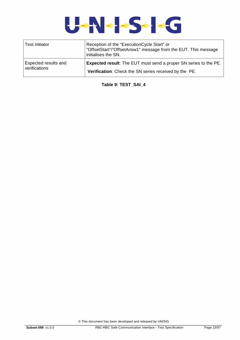
Test initiator Reception of the “ExecutionCycle Start” or ”OffsetStart”/”OffsetAnsw1” message from the EUT. This message initialises the SN.
Expected results and verifications
Expected result : The EUT must send a proper SN series to the PE.
Verification : Check the SN series received by the PE.
Table 9: TEST_SAI_4

© This document has been developed and released by UNISIG
Subset-099 v1.0.0 RBC-RBC Safe Communication Interface - Test Specification Page 24/97
5.3 EXECUTION CYCLE DEFENCE TECHNIQUE
5.3.1 LIST OF EC FUNCTIONAL TESTS
5.3.1.1.1 TEST 5: initialisation procedure performed by the PE (connection requested by the peer entity) - this test checks that the EUT is able to accept the initialisation of a connection using the EC defence technique.
5.3.1.1.2 TEST 6: initialisation procedure performed by the EUT (connection requested to the peer entity) - this test checks that the EUT is able to perform the initialisation of a connection using the EC defence technique.
5.3.1.1.3 TEST 7: EC incrementation in reception - this test checks that the EUT accepts an EC value incremented by one at each EC period of the peer. This test does not include zero-crossing and long-term tests.
5.3.1.1.4 TEST 8: EC incrementation in transmission - this test checks that the EUT produces an EC value incremented by one at each EC period. This test does not include zero-crossing and long-term tests.
5.3.1.1.5 TEST 9: procedure for the detection of transmission delay initiated by the PE - this test checks that the EUT is able to process the procedure for detection of transmission delay initiated by the PE.
5.3.1.1.6 TEST 10: procedure for the detection of transmission delay initiated by the EUT - this test checks that the EUT is able to initiate and process the procedure for detection of transmission delay.

© This document has been developed and released by UNISIG
Subset-099 v1.0.0 RBC-RBC Safe Communication Interface - Test Specification Page 25/97
5.3.2 TEST 5: INITIALISATION PROCEDURE PERFORMED BY THE PE
5.3.2.1 Test overview
5.3.2.1.1 This test is similar to the one performed in the section TEST 1: Connection and SN initialisation (connection requested by the PE).
5.3.2.1.2 This test assumes the above-mentioned test has been performed successfully. Only the functions not tested in the above-mentioned section are defined and performed:
a) the SS Responder must accept a random initial EC value;
b) the ratio R (cfr. § 5.4.9.4. of Subset-098) must be correctly computed.
5.3.2.2 Traceability with Subset-098
5.3.2.2.1 The initialisation procedure is defined in Subset-098, §5.4.5.1.
5.3.2.2.2 The Execution Cycle period format is defined in Subset-098, § 5.4.9.3.9.
5.3.2.2.3 The format of the initialisation message (ExecutionCycle Start) is defined in Subset-098, § 5.4.9.3.8.
5.3.2.2.4 The format of the primitives between the SLE and the SAI is compliant with Subset-037.
5.3.2.2.5 The computation of the parameters R is defined in §5.4.9.4.3 of Subset-098.
5.3.2.3 TEST 5: TEST_SAI_5
Test identifier TEST_SAI_5
Initial conditions No connection between the RBC’s
Preliminary steps 1. Establishment of the connection at the TCP/IP level
2. Establishment of the connection at the ALE level
3. Exchange of the AU 1 SaPDU, AU2 SaPDU, AU3 SaPDU and AR SaPDU messages between SLE layers.
Test initiator Reception of the first Sa-Data indication (ExecutionCycleStart message) by the PE.
Expected results and verifications
Expected result 1: The EUT SAI must accept a random “EC” value in the “ExecutionCycleStart” message.
Verification : The EUT must answer sending a ExecutionCycleStart message to the peer entity.
Table 10: TEST_SAI_5

© This document has been developed and released by UNISIG
Subset-099 v1.0.0 RBC-RBC Safe Communication Interface - Test Specification Page 26/97
5.3.3 TEST 6: INITIALISATION PROCEDURE PERFORMED BY THE EUT
5.3.3.1 Test overview
5.3.3.1.1 This test is similar to the one performed in the section TEST 2: Connection and SN initialisation (connection requested to the PE).
5.3.3.1.2 This test assumes the above-mentioned test has been performed successfully. Only the functions not tested in the above-mentioned section are defined and performed:
a) the PE must accept the initial EC sent in the ExecutionCycleStart message;
b) the ratio R (see. § 5.4.9.4. of Subset-098) must be correctly computed.
5.3.3.1.3 Note: There is no requirement on the initial EC value.
5.3.3.2 Traceability with Subset-098
5.3.3.2.1 The initialisation procedure is defined in Subset-098, §5.4.9.3.
5.3.3.2.2 The Execution Cycle period format is defined in Subset-098, § 5.4.9.2.
5.3.3.2.3 The format of the initialisation message (ExecutionCycle Start) is defined in Subset-098, § 5.4.9.3.
5.3.3.2.4 The format of the primitives between the SLE and the SAI is compliant with Subset-037.
5.3.3.2.5 The computation of the parameter R is defined in §. 5.4.9.4 of Subset-098.
5.3.3.3 TEST 6: TEST_SAI_6
Test identifier TEST_SAI_6
Initial conditions No connection between the RBC’s
Preliminary steps 1. Establishment of the connection at the TCP/IP level
2. Establishment of the connection at the ALE level
3. Exchange of the AU 1 SaPDU, AU2 SaPDU, AU3 SaPDU and AR SaPDU messages between SLE layers.
Test initiator Transmission of the first Sa-Data request (ExecutionCycleStart message) by the EUT.
© This document has been developed and released by UNISIG
Subset-099 v1.0.0 RBC-RBC Safe Communication Interface - Test Specification Page 27/97
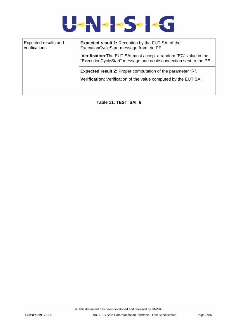
Expected result 1: Reception by the EUT SAI of the ExecutionCycleStart message from the PE.
Verification :The EUT SAI must accept a random “EC” value in the “ExecutionCycleStart” message and no disconnection sent to the PE.
Expected results and verifications
Expected result 2: Proper computation of the parameter “R”.
Verification : Verification of the value computed by the EUT SAI.
Table 11: TEST_SAI_6
© This document has been developed and released by UNISIG
Subset-099 v1.0.0 RBC-RBC Safe Communication Interface - Test Specification Page 28/97
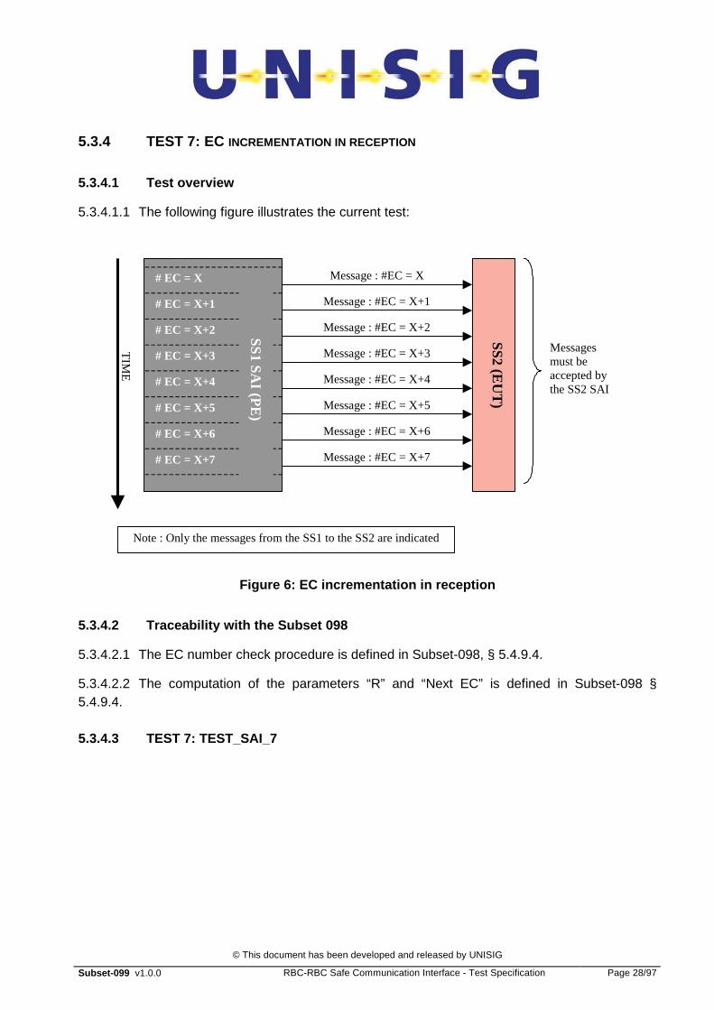
5.3.4 TEST 7: EC INCREMENTATION IN RECEPTION
5.3.4.1 Test overview
5.3.4.1.1 The following figure illustrates the current test:
SS2 (EU
T)
Message : #EC = X
TIM
E
Note : Only the messages from the SS1 to the SS2 are indicated
Message : #EC = X+5
Message : #EC = X+6
Message : #EC = X+1
Message : #EC = X+7
Message : #EC = X+2
Message : #EC = X+4
Message : #EC = X+3
SS1 SAI (P
E)
# EC = X
# EC = X+1
# EC = X+2
# EC = X+3
# EC = X+4
# EC = X+6
# EC = X+5
# EC = X+7
Messages must be accepted by the SS2 SAI
Figure 6: EC incrementation in reception
5.3.4.2 Traceability with the Subset 098
5.3.4.2.1 The EC number check procedure is defined in Subset-098, § 5.4.9.4.
5.3.4.2.2 The computation of the parameters “R” and “Next EC” is defined in Subset-098 § 5.4.9.4.
5.3.4.3 TEST 7: TEST_SAI_7

© This document has been developed and released by UNISIG
Subset-099 v1.0.0 RBC-RBC Safe Communication Interface - Test Specification Page 29/97
Test identifier TEST_SAI_7
Initial conditions No connection between the RBC’s
Preliminary steps 1. Establishment of the connection and exchange of the “ExecutionCycle Start” message between SAI layers.
Test initiator Reception by the PE of the “ExecutionCycle Start” message from the EUT.
Expected results and verifications
Expected result 1: Acceptation by the EUT SAI of the message series from the PE.
Verification : No disconnection due to EC rejection.
Table 12: TEST_SAI_7

© This document has been developed and released by UNISIG
Subset-099 v1.0.0 RBC-RBC Safe Communication Interface - Test Specification Page 30/97
5.3.5 TEST 8: EC INCREMENTATION IN TRANSMISSION
5.3.5.1 Test overview
5.3.5.1.1 The following figure illustrates the current test:
SS
2 SA
I (PE
)
Message : #EC = X
TIM
E
Note : Only the messages from the SS1 to the SS2 are indicated
Message : #EC = X+5
Message : #EC = X+6
Message : #EC = X+1
Message : #EC = X+7
Message : #EC = X+2
Message : #EC = X+4
Message : #EC = X+3
SS1 SAI (E
UT
)
# EC = X
# EC = X+1
# EC = X+2
# EC = X+3
# EC = X+4
# EC = X+6
# EC = X+5
# EC = X+7
Messages must be accepted by the SS2 SAI
Figure 7: EC incrementation in transmission
5.3.5.2 Traceability with the Subset 098
5.3.5.2.1 The EC number check procedure is defined in Subset-098, § 5.4.9.4.
5.3.5.2.2 The computation of the parameters R and Next EC is defined in § 5.4.9.4 of Subset-098.
5.3.5.3 TEST 8: TEST_SAI_8
© This document has been developed and released by UNISIG
Subset-099 v1.0.0 RBC-RBC Safe Communication Interface - Test Specification Page 31/97
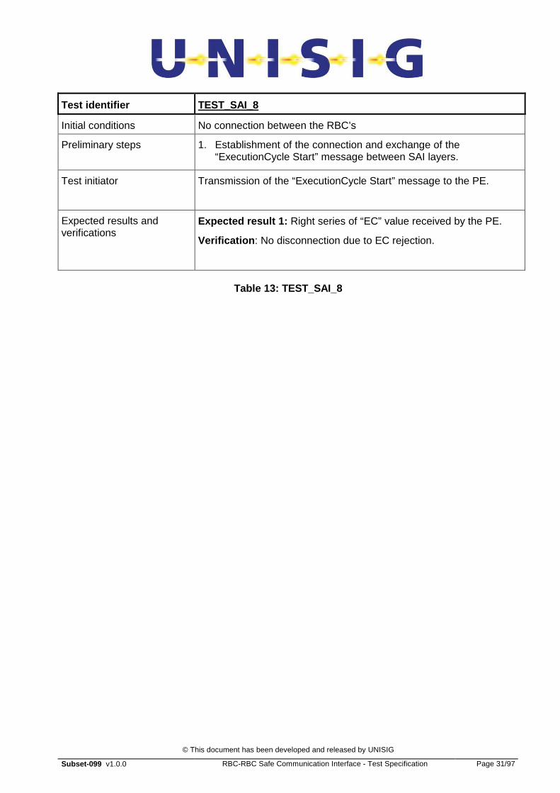
Test identifier TEST_SAI_8
Initial conditions No connection between the RBC’s
Preliminary steps 1. Establishment of the connection and exchange of the “ExecutionCycle Start” message between SAI layers.
Test initiator Transmission of the “ExecutionCycle Start” message to the PE.
Expected results and verifications
Expected result 1: Right series of “EC” value received by the PE.
Verification : No disconnection due to EC rejection.
Table 13: TEST_SAI_8

© This document has been developed and released by UNISIG
Subset-099 v1.0.0 RBC-RBC Safe Communication Interface - Test Specification Page 32/97
5.3.6 TEST 9: PROCEDURE FOR TRANSMISSION DELAY DETECTION INITIATED BY THE PE
5.3.6.1 Test overview
5.3.6.1.1 This test checks that EUT is able to answer a procedure for detection of transmission delay initiated byPE. The following figure illustrates this procedure:
Sa-Data. Indication
EUT PE
Sa-Data. Request
Sa-Data. Indication
Sa-Data. Request
E URORADI O
E U R O R A D I O
S A I
S A I
DT SaPDU (Appl. Message with
ACK)
DT SaPDU (Appl. Message with
request of ACK)
Set TSyn
Stop TSyn
Transmission of application data
Figure 8: Procedure for transmission delay detectio n initiated by peer PE
5.3.6.2 Traceability with the Subset 098
5.3.6.2.1 The procedure for detection of transmission delay is defined in Subset-098, § 5.4.9.6.
5.3.6.3 TEST 9: TEST_SAI_9
Test identifier TEST_SAI_9
Initial conditions No connection between the RBC’s
Preliminary steps 1. Establishment of the connection at the SAI level
2. Transmission of data between the RBC’s
Test initiator The PE must initiate the Procedure for “detection of transmission delay” (application message with “Request of Acknowledgement”)
Expected results and verifications
Expected result : The EUT must answer to the above-mentioned message with an application message with “ACK”
Verification : The PE checks that it receives the expected message within the expected time window (Tsyn)..

© This document has been developed and released by UNISIG
Subset-099 v1.0.0 RBC-RBC Safe Communication Interface - Test Specification Page 33/97
Table 14: TEST_SAI_9

© This document has been developed and released by UNISIG
Subset-099 v1.0.0 RBC-RBC Safe Communication Interface - Test Specification Page 34/97
5.3.7 TEST 10: PROCEDURE FOR TRANSMISSION DELAY DETECTION INITIATED BY THE EUT
5.3.7.1 Test overview
5.3.7.1.1 These tests check that EUT is able to initiate a procedure for detection of transmission delay and the result of the procedure.
5.3.7.1.2 The first test (TEST 10.1) consists of checking that EUT is able to initiate the procedure and accept a valid answer from the peer PE received within the expected time window (Tsyn).
5.3.7.1.3 The second test (TEST 10.2) consists of checking that EUT is able to initiate the procedure and, after Tsucc_er following attempts, releases the connection if the answers from peer PE are always received outside the valid time window Tsyn or are not received.
5.3.7.1.4 The following figure illustrates the test:

© This document has been developed and released by UNISIG
Subset-099 v1.0.0 RBC-RBC Safe Communication Interface - Test Specification Page 35/97
Sa-Data. Indication
PE EUT
Sa-Data. Request
Sa-Data. Indication
Sa-Data. Request
E URORADI O
E U R O R A D I O
S A I
S A I
DT SaPDU (Appl. Message with
ACK)
DT SaPDU (Appl. Message with
request of ACK)
Set TSyn
Stop TSyn
Transmission of application data
Sub-tests TEST_SAI_10-1
Sa-Data. Indication
Sa-Data. Request
Sa-Data. Indication
Sa-Data. Request DT SaPDU
(Appl. Message with ACK)
DT SaPDU (Appl. Message with
request of ACK)
Set TSyn
END TSyn
Transmission of application data
Sub-tests TEST_SAI_10-2
Set TSyn
END TSyn
Indication to the SAI user of the procedure failure
Figure 9: Procedure for transmission delay detectio n initiated by SS1
5.3.7.2 Traceability with the Subset 098
5.3.7.2.1 The procedure for detection of transmission delay is defined in Subset-098, § 5.4.9.6.
5.3.7.2.2 The procedures for error handling are defined in [Subset-098], §5.4.10.
5.3.7.3 TEST 10.1: TEST_SAI_10-1
Test identifier TEST_SAI_10-1

© This document has been developed and released by UNISIG
Subset-099 v1.0.0 RBC-RBC Safe Communication Interface - Test Specification Page 36/97
Initial conditions No connection between the RBC’s
Preliminary steps 1. Establishment of the connection at the SAI level
2. Transmission of data between the RBC’s
Test initiator The EUT must initiate the Procedure for “detection of transmission delay” (application message with “Request of Acknowledgement”)
Expected results and verifications
Expected result : The PE must answer to the above-mentioned message with an application message with “ACK”, and this message must be delivered to the EUT within the valid time window.
Verification : Reception of the “ACK” message by the EUT initiating the procedure for “detection of transmission delay”.
Table 15: TEST_SAI_10-1
5.3.7.4 TEST 10.2: TEST_SAI_10-2
Test identifier TEST_SAI_10-2
Initial conditions No connection between the RBC’s
Preliminary steps 1. Establishment of the connection at the SAI level
2. Transmission of data between theRBC’s
Test initiator The EUT must initiate the Procedure for “detection of transmission delay” (application message with “Request of Acknowledgement”)
Expected results and verifications
Expected result : The PE must answer to the above-mentioned message with an application message with “ACK”, but this message must be delivered to the EUT outside of the valid time window.
Otherwise the PE must not answer to the above-mentioned message with an application message with “ACK”.
Verification : expiration of timer Tsyn for Tsucc_er times and then release of the safe connection.
Table 16: TEST_SAI_10-2

© This document has been developed and released by UNISIG
Subset-099 v1.0.0 RBC-RBC Safe Communication Interface - Test Specification Page 37/97
5.4 TRIPLE TIME STAMPING DEFENCE TECHNIQUE
5.4.1 LIST OF TTS FUNCTIONAL TESTS
5.4.1.1.1 TEST 11: Clock offset estimation performed by the EUT. - this test checks that the tested subsystem is able to initiate the clock offset estimation procedure.
5.4.1.1.2 TEST 12: Clock offset estimation performed by the PE. - this test checks that the tested subsystem is able to answer a clock offset estimation procedure initiated by the peer subsystem.
5.4.1.1.3 TEST 13: Exchange of application data. - this test checks that the EUT is able to sent and receive application data.
5.4.1.1.4 TEST 14: Initiation of clock offset update procedure. - this test checks that the EUT is able to initiate the clock offset update procedure.
5.4.1.1.5 TEST 15: Clock offset update procedure initiated by the PE. - this test checks that the EUT is able to answer a clock offset update procedure initiated by the PE.
© This document has been developed and released by UNISIG
Subset-099 v1.0.0 RBC-RBC Safe Communication Interface - Test Specification Page 38/97
5.4.2 TEST 11: CLOCK OFFSET ESTIMATION PERFORMED BY THE EUT
5.4.2.1 Test overview
5.4.2.1.1 The current test checks if the EUT is able to initiate and perform the clock offset estimation procedure.
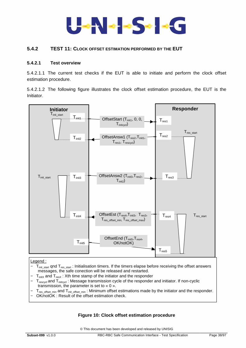
5.4.2.1.2 The following figure illustrates the clock offset estimation procedure, the EUT is the Initiator.
Initiator Responder
OffsetStart (Tinit1, 0, 0, Tinitcycl)
Tinit1 Tres1
OffsetAnsw1 (Tres2,Tinit1, Tres1, Trescycl)
OffsetAnsw2 (Tinit3,Tres2, Tinit2)
Tinit5
OffsetEst (Tres4,Tinit3, Tres3, Tres_offset_min, Tres_offset_max)
OffsetEnd (Tinit5,Tres4, OK/notOK)
Tinit_start
Tinit2 Tres2
Tres3
Tres_start
Legend : − Tinit_start qnd Tres_start : Initialisation timers. If the timers elapse before receiving the offset answers
messages, the safe conection will be released and restarted. − TinitX and TresX : Xth time stamp of the initiator and the responder − Trescycl and Tinitcycl : Message transmission cycle of the responder and initiator. If non-cyclic
transmission, the parameter is set to « 0 ». − Tres_offset_min and Tinit_offset_min : Minimum offset estimations made by the initiator and the responder. − OK/notOK : Result of the offset estimation check.
Tinit3
Tinit4
Tinit_start
Tres4
Tres5
Tres_start
Figure 10: Clock offset estimation procedure

© This document has been developed and released by UNISIG
Subset-099 v1.0.0 RBC-RBC Safe Communication Interface - Test Specification Page 39/97
5.4.2.1.3 This test is similar to the one performed in the section “TEST 2: Connection and SN initialisation (connection requested to the PE)”
5.4.2.1.4 This test assumes that the above-mentioned test has been performed successfully. Only the functions not tested in the above-mentioned section are defined and performed:
a) Sending the OffsetAnsw2 message and starting the Tinit_start timer (SUB_TEST 11.1)
b) Processing the OffsetEst message and stopping the Tinit_start timer (SUB_TEST 11.2)
c) Sending the OffsetEnd message (SUB_TEST 11.2)
5.4.2.2 Traceability with the Subset 098
5.4.2.2.1 The messages are specified in § 5.4.8.4 of Subset-098
5.4.2.2.2 The clock offset estimation procedure is specified in Subset-098, §5.4.8.5 .
5.4.2.3 SUB-TEST 11.1: TEST_SAI_11-1
5.4.2.3.1 This subtest checks that the SS under test:
a) sends the OffsetAnsw2 message;
b) starts the Tinit_start timer.
Test identifier TEST_SAI_11-1
Initial conditions No connection between the RBC’s
Preliminary steps Request of a connection by the EUT SAI User.
The tested SAI must send a Sa-Connect request to the EUT SL Euroradio.
Test initiator The connection must be established at the TCP/IP, ALE and SL Euroradio level between the two devices.
The tested SAI must send the OffsetStart message and receive back the OffsetAnsw1 message
Expected result 1: The tested SAI must send the OffsetAnsw2 message to the PE SAI
Verification : Message OffsetAnsw2 received by the peer entity
Expected results and verifications
Expected result 2: Start the Tinit_start timer
Verification : Connection release at the timer elapsing
Table 17: TEST_SAI_11-1
© This document has been developed and released by UNISIG
Subset-099 v1.0.0 RBC-RBC Safe Communication Interface - Test Specification Page 40/97
5.4.2.4 SUB-TEST 11.2: TEST_SAI_11-2
5.4.2.4.1 This subtest checks that the EUT:
a) processes of the OffsetEst message;
b) stops the Tinit_start timer;
c) sends of the OffsetEnd message.
Test identifier TEST_SAI_11-2
Initial conditions No connection between the RBC’s
Preliminary steps Request of a connection by the EUT SAI User.
The tested SAI must send a Sa-Connect request to the EUT SL Euroradio.
Test initiator The connection must be established at the TCP/IP, ALE and SL Euroradio level between the two devices.
The tested SAI must send the OffsetAnsw2 message and receive back the OffsetEst message
Expected result 1: The tested SAI must process the OffsetEst and send the OffsetEnd message to the peer SAI
Verification : Message OffsetEnd received by the peer entity
Expected results and verifications
Expected result 2: Stop the Tinit_start timer
Verification : No disconnection at the timer elapsing
Table 18: TEST_SAI_11-2

© This document has been developed and released by UNISIG
Subset-099 v1.0.0 RBC-RBC Safe Communication Interface - Test Specification Page 41/97
5.4.3 TEST 12: CLOCK OFFSET ESTIMATION PERFORMED BY THE PE
5.4.3.1 Test overview
5.4.3.1.1 The current test checks if the EUT is able to answer a clock offset estimation procedure.
5.4.3.1.2 Figure 10 illustrates the clock offset estimation procedure. The EUT test is the responder.
5.4.3.1.3 This test is similar to the one performed in the section “TEST 1: Connection and SN initialisation (connection requested by the PE)”.
5.4.3.1.4 This test assumes the above-mentioned test has been performed successfully. Only the functions not tested in the above-mentioned section are specified and performed:
a) sending the OffsetEst message (TEST 12.1);
b) starting the Tres_start timer (TEST 12.1);
c) processing the OffsetEnd message (TEST 12.2);
d) stopping the Tres_start timer (TEST 12.2).
5.4.3.2 Traceability with Subset-098
5.4.3.2.1 The messages are specified in §5.4.8.4 of Subset-098.
5.4.3.2.2 The clock offset estimation procedure is specified in Subset-098, §5.4.8.5.
5.4.3.3 TEST 12.1: TEST_SAI_12-1
5.4.3.3.1 This subtest checks that the EUT:
a) sends the OffsetEst message;
b) starts the Tres_start timer.
Test identifier TEST_SAI_12-1
Initial conditions No connection between the RBC’s
Preliminary steps Request of a connection by the PE SAI User.
The tested SAI must process the Sa-Connect request sent by the peer entity.
Test initiator The connection must be established at the TCP/IP, ALE and SL Euroradio level between the two devices.
The tested SAI must send the OffsetAnsw1 message and receive back the OffsetAnsw2 message

© This document has been developed and released by UNISIG
Subset-099 v1.0.0 RBC-RBC Safe Communication Interface - Test Specification Page 42/97
Expected result 1: The tested SAI must send the OffsetEst message to the PE SAI after having processed the OffsetAnsw2 message.
Verification : Message OffsetEst received by the peer entity
Expected results and verifications
Expected result 2: Start the Tres_start timer
Verification : Connection release at the timer elapsing
Table 19: TEST_SAI_12-1
5.4.3.4 TEST 12.2: TEST_SAI_12-2
5.4.3.4.1 This subtest checks that the EUT:
a) processes the OffsetEnd message (TEST 12.2);
b) stops the Tres_start timer (TEST 12.2).
Test identifier TEST_SAI_12-2
Initial conditions No connection between the RBC’s
Preliminary steps Request of a connection by the PE SAI User.
The tested SAI must process the Sa-Connect request sent by the peer entity.
Test initiator The connection must be established at the TCP/IP, ALE and SL Euroradio level between the two devices.
The tested SAI must send the OffsetEst message and receive back the OffsetEnd message
Expected result 1: The tested SAI must process the OffsetEnd message.
Verification : Exchange of “Keep Awake” messages or application messages after the reception of OffsetEnd
Expected results and verifications
Expected result 2: Stop the Tres_start timer
Verification : No disconnection at the timer elapsing
Table 20: TEST_SAI_12-2

© This document has been developed and released by UNISIG
Subset-099 v1.0.0 RBC-RBC Safe Communication Interface - Test Specification Page 43/97
5.4.4 TEST 13: EXCHANGE OF APPLICATION DATA
5.4.4.1 Test overview
5.4.4.1.1 This test confirms that application data are exchanged between the two entities.
5.4.4.2 Traceability with the Subset 098
5.4.4.2.1 The application data messages are specified in §5.4.8.6 of Subset-098.
5.4.4.3 TEST 13: TEST_SAI_13
Test identifier TEST_SAI_13
Initial conditions No connection between the RBC’s
Preliminary steps Establishment of connection and execution of the “Clock offset estimation” procedure
Test initiator NA
Expected result 1: Application data sent by the PE shall be processed by the EUT SAI.
Verification : Reception of the application data by the EUT SAI user entity.
Expected results and verifications
Expected result 2: Sending of application data.
Verification : Reception of the application data by the PE SAI user entity.
Table 21: TEST_SAI_13
© This document has been developed and released by UNISIG
Subset-099 v1.0.0 RBC-RBC Safe Communication Interface - Test Specification Page 44/97
5.4.5 TEST 14: INITIATION OF CLOCK OFFSET ESTIMATION UPDATE PROCEDU RE
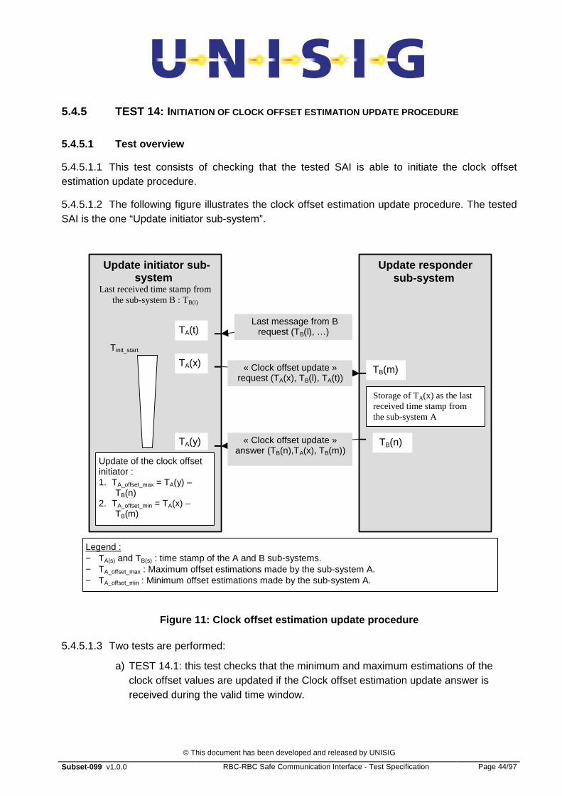
5.4.5.1 Test overview
5.4.5.1.1 This test consists of checking that the tested SAI is able to initiate the clock offset estimation update procedure.
5.4.5.1.2 The following figure illustrates the clock offset estimation update procedure. The tested SAI is the one “Update initiator sub-system”.
Update initiator sub -system
Last received time stamp from the sub-system B : TB(l)
Update responder sub-system
« Clock offset update » request (TA(x), TB(l), TA(t))
TA(x) TB(m)
« Clock offset update » answer (TB(n),TA(x), TB(m))
Update of the clock offset initiator : 1. TA_offset_max = TA(y) –
TB(n) 2. TA_offset_min = TA(x) –
TB(m)
TA(y) TB(n)
Legend : − TA(s) and TB(s) : time stamp of the A and B sub-systems. − TA_offset_max : Maximum offset estimations made by the sub-system A. − TA_offset_min : Minimum offset estimations made by the sub-system A.
Storage of TA(x) as the last received time stamp from the sub-system A
Last message from B request (TB(l), …) TA(t)
Tinit_start
Figure 11: Clock offset estimation update procedure
5.4.5.1.3 Two tests are performed:
a) TEST 14.1: this test checks that the minimum and maximum estimations of the clock offset values are updated if the Clock offset estimation update answer is received during the valid time window.
© This document has been developed and released by UNISIG
Subset-099 v1.0.0 RBC-RBC Safe Communication Interface - Test Specification Page 45/97
b) TEST 14.2: this test checks that, if the Clock offset estimation update answer is not received during the valid time window, the connection is released (conf Tinit_start near 0 and release of the connection at the first error). Note: this test is possible only if the Tinistart message can be modified after connection establishment.
5.4.5.1.4 The tested SAI shall be configured to release the connection if the Clock offset estimation update procedure fails.
5.4.5.2 Traceability with Subset-098
5.4.5.2.1 The Clock offset estimation update procedure is specified in § 5.4.8.7 of Subset-098.
5.4.5.3 TEST 14.1: TEST_SAI_14-1
Test identifier TEST_SAI_14-1
Initial conditions No connection between the RBC’s
Preliminary steps Establishment of connection, execution of the “Clock offset estimation” procedure and exchange of application data.
Test initiator NA
Expected result 1: The tested SAI shall initiate a “Clock offset estimation update” procedure by sending the “Clock offset update” request.
Verification : Reception and processing of the “Clock offset update” answer from the PE SAI entity.
Expected result 2: The Clock offset update” answer must be received within the valid time window.
Verification : No release of the connection.
Expected results and verifications
Expected result 3: The Clock offset update” answer must be processed by the tested SAI.
Verification : Check that the Toffset_min and Toffset_max values have been updated.
Table 22: TEST_SAI_14-1
5.4.5.4 TEST 14.2: TEST_SAI_14-2
5.4.5.4.1 The Tinit_start timer shall be set to 0 sec.
Test identifier TEST_SAI_14-2
Initial conditions No connection between the RBC’s

© This document has been developed and released by UNISIG
Subset-099 v1.0.0 RBC-RBC Safe Communication Interface - Test Specification Page 46/97
Preliminary steps Establishment of connection, execution of the “Clock offset estimation” procedure and exchange of application data.
Test initiator NA
Expected result 1: The tested SAI shall initiate a “Clock offset estimation update” procedure by sending the “Clock offset update” request.
Verification : Reception and processing of the “Clock offset update” answer from the PE SAI.
Expected results and verifications
Expected result 2: The “Clock offset update” answer will be received out of the valid time window.
Verification : Release of the connection.
Table 23: TEST_SAI_14-2

© This document has been developed and released by UNISIG
Subset-099 v1.0.0 RBC-RBC Safe Communication Interface - Test Specification Page 47/97
5.4.6 TEST 15: CLOCK OFFSET UPDATE PROCEDURE INITIATED BY THE PE
5.4.6.1 Test overview
5.4.6.1.1 This test consists of checking if the tested SAI is able to answer a clock offset estimation update procedure initiated by the PE.
5.4.6.1.2 Figure 11 illustrates the clock offset estimation update procedure. The tested SAI is the “Update responder sub-system”.
5.4.6.2 Traceability with Subset-098
5.4.6.2.1 The Clock offset estimation update procedure is specified in § 5.4.8.7 of Subset-098.
5.4.6.3 TEST 15: TEST_SAI_15
Test identifier TEST_SAI_15
Initial conditions No connection between the RBC’s
Preliminary steps Establishment of connection, execution of the “Clock offset estimation” procedure and exchange of application data.
Test initiator The PE SAI shall initiate a “Clock offset estimation update” procedure by sending the “Clock offset update” request.
Expected result 1: Processing of the “Clock offset update” request and sending of the “Clock offset update” answer to the PE SAI .
Verification : Reception by the PE SAI of the “Clock offset update” answer.
Expected results and verifications
Expected result 2: The Clock offset update” answer must be received by the PE SAI within the valid time window.
Verification : No release of the connection and check that the Toffset_min and Toffset_max values have been updated.
Table 24: TEST_SAI_15
© This document has been developed and released by UNISIG
Subset-099 v1.0.0 RBC-RBC Safe Communication Interface - Test Specification Page 48/97
6. ALE TEST
6.1 FUNCTIONALITY SET OF THE ALE USER
6.1.1.1.1 The ALE user implements at least the following functions:
a) connection management: initiation of a connection at the ALE level;
b) transmission of application data (the content of the application data shall be predefined);
c) reception of application data (the content of the application data shall be predefined);
d) optionally, display to the user and record the history of the alarms and connection status provided by the ALE.
6.2 CONFIGURATION PARAMETERS
6.2.1 TCP/IP CONFIGURATION PARAMETERS
6.2.1.1.1 The TCP/IP configuration of the equipments EUT and PE shall be implemented in conformance with Subset-098.
6.2.1.1.2 The TCP/IP network shall have logical or physical redundant links to allow redundancy management to be tested.
6.2.2 ALE CONFIGURATION PARAMETERS
6.2.2.1.1 The following ALE configuration parameters are relevant for testing:
• Class (A or D)
• Missing packets tolerated for Class D (Y or N)
6.2.2.1.2 The same Class shall be used for the EUT and the PE.
6.2.2.1.3 Tolerance of missing packets can be different for the EUT and the PE.
6.3 LIST OF FUNCTIONAL TESTS FOR CLASS D
6.3.1
6.3.1.1.1 Test_ALE 1: ALEPKT correctly formed. Subset-098 defines the format of messages to be exchanged between two peers. These tests will check that the ALEPKTs are properly formed by the sender and properly interpreted by the receiver.
© This document has been developed and released by UNISIG
Subset-099 v1.0.0 RBC-RBC Safe Communication Interface - Test Specification Page 49/97
6.3.1.1.2 Test_ALE 2: Creation of a Class D ALE connection.These tests check that Class D connections are properly created (two TCP links, correct transport sequence numbers etc).
6.3.1.1.3 Test_ALE 3: Data Transfer on a Class D connection. These tests check that data is correctly sent on both TCP channels and properly processed by the receiver.
6.3.1.1.4 Test_ALE 4: Connection Release for Class D connection. These tests check that normal and abnormal connection release takes place as specified.
6.3.1.1.5 Test_ALE 5: Redundancy Management of a Class D connection. These tests check that transmission error conditions are handled in accordance with the specification.
6.4 LIST OF FUNCTIONAL TESTS FOR CLASS A (OPTIONAL)
6.4.1.1.1 Test_ALE 6: ALEPKTs correctly formed. Subset-098 defines the format of messages to be exchanged between two peers. These tests check that the ALEPKTs are properly formed by the sender and properly interpreted by the receiver.
6.4.1.1.2 Test_ALE 7: Creation of a Class A ALE connectionThese tests check that Class A connections are properly created (two TCP links, correct transport sequence numbers etc).
6.4.1.1.3 Test_ALE 8: Data Transfer on a Class A connection. These tests check that data is correctly sent on one TCP channel and properly processed by the receiver.
6.4.1.1.4 Test_ALE 9: Connection Release for Class A connectionThese tests check that normal and abnormal connection release takes place as specified.
6.4.1.1.5 Test_ALE 10: Redundancy Management of a Class A connection. These tests check that transmission error conditions are handled in accordance with the specification.

© This document has been developed and released by UNISIG
Subset-099 v1.0.0 RBC-RBC Safe Communication Interface - Test Specification Page 50/97
6.5 CLASS D TESTS
6.5.1 TEST_ALE 1: ALEPKT S CORRECTLY FORMED
6.5.1.1 Test objectives
6.5.1.1.1 The objective of these tests is to prove that ALEPKTs are properly formed.
6.5.1.2 Test overview
6.5.1.2.1 Packets will be sent and received by the EUT during various types of activity such as connection establishment, connection release, data transfer and redundancy management.
6.5.1.3 Traceability
Test Description Traceability with [Subset-098]
1.1 Correct formation of ALEPKT AU1 6.4.5/6.5.2.4
1.2 Correct formation of ALEPKT AU2 6.4.5/6.5.2.4
1.3 Correct formation of ALEPKT data 6.4.5/6.5.2.4/6.5.3.2
1.4 Correct formation of ALEPKT DI 6.4.5/6.5.2.4/6.5.4.4
1.5 Proper interpretation of ALEPKT AU1 6.4.5/6.5.2.4
1.6 Proper interpretation of ALEPKT AU2 6.4.5/6.5.2.4
1.7 Proper interpretation of ALEPKT data 6.4.5/6.5.2.4/6.5.3.2
1.8 Proper interpretation of ALEPKT DI 6.4.5/6.5.2.4/6.5.4.4
Note: Tests 1.3 and 1.7 cover ALEPKTs containing AU3.
6.5.1.4 TEST_ALE_1-1
6.5.1.4.1 The objective of this test is to ensure correct formation of AU1 ALEPKT.
6.5.1.4.2 EUT is the initiator, PE is the responder.
6.5.1.4.3 Test Description
Test identifier TEST_ALE_1-1
Initial conditions No connection between the EUT and PE
Preliminary steps 1. Establishment of the connections at the TCP/IP level
© This document has been developed and released by UNISIG
Subset-099 v1.0.0 RBC-RBC Safe Communication Interface - Test Specification Page 51/97
(see Test_ALE_2-2)
Test initiator Connection request (AU1 SaPDU) from the EUT ALE user.
Expected results Verification
AU1 ALEPKT format as defined in [Subset-098]
Examination of trace from ethernet monitor or PDU logger
Connection request recognised by PE.
The PE user shall receive a “T-Connect indication”.
Reception of “T-Connect Confirm” by the EUT user from the ALE.
Table 25: TEST_ALE_1-1
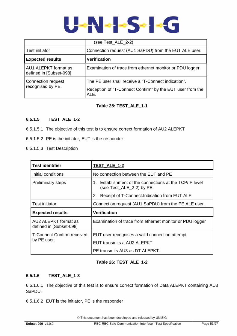
6.5.1.5 TEST_ALE_1-2
6.5.1.5.1 The objective of this test is to ensure correct formation of AU2 ALEPKT
6.5.1.5.2 PE is the initiator, EUT is the responder
6.5.1.5.3 Test Description
Test identifier TEST_ALE_1-2
Initial conditions No connection between the EUT and PE
Preliminary steps 1. Establishment of the connections at the TCP/IP level (see Test_ALE_2-2) by PE.
2. Receipt of T-Connect.Indication from EUT ALE
Test initiator Connection request (AU1 SaPDU) from the PE ALE user.
Expected results Verification
AU2 ALEPKT format as defined in [Subset-098]
Examination of trace from ethernet monitor or PDU logger
T-Connect.Confirm received by PE user.
EUT user recognises a valid connection attempt
EUT transmits a AU2 ALEPKT
PE transmits AU3 as DT ALEPKT.
Table 26: TEST_ALE_1-2
6.5.1.6 TEST_ALE_1-3
6.5.1.6.1 The objective of this test is to ensure correct formation of Data ALEPKT containing AU3 SaPDU.
6.5.1.6.2 EUT is the initiator, PE is the responder

© This document has been developed and released by UNISIG
Subset-099 v1.0.0 RBC-RBC Safe Communication Interface - Test Specification Page 52/97
6.5.1.6.3 Test Description
Test identifier TEST_ALE 1-3
Initial conditions No connection between the EUT and PE
Preliminary steps 1. Establishment of the connections at the TCP/IP level (see Test_ALE_2-2)
2. Receipt by EUT user of T-Connect.Confirm from EUT ALE
Test initiator Connection request (AU1 SaPDU) from the EUT ALE user.
Expected results Verification
Data ALEPKT containing AU3 transmitted by EUT. Packet format as defined in [Subset-098]
Examination of trace from ethernet monitor or PDU logger
The PE user shall receive a “T-Data.Indication” with AU3 SaPDU.
Data recognised by PE (AU3 SaPDU).
Reception of AR SaPDU in DT ALEPKT by the EUT user from the PE .
Table 27: TEST_ALE_1-3
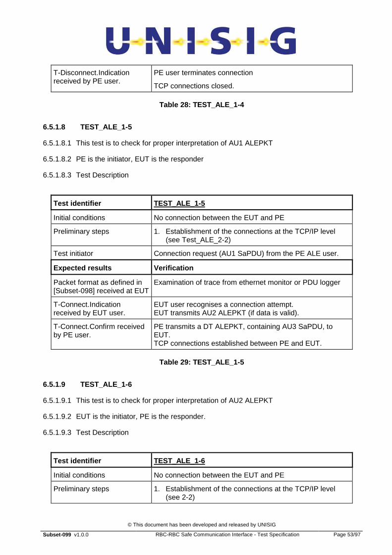
6.5.1.7 TEST_ALE_1-4
6.5.1.7.1 The objective of this test is to ensure correct formation of DiscALEPKT
6.5.1.7.2 EUT is the initiator, PE is the responder. EUT is the disconnecting entity.
6.5.1.7.3 Test Description
Test identifier TEST_ALE_1-4
Initial conditions Connection established between the EUT and PE
Preliminary steps 1. Establishment of the connections at the TCP/IP level (see TEST_ALE_2-2)
2. Establishment of (safe) connection between PE and EUT (see [Subset-098])
Test initiator T-Disconnect.Request (Disc SaPDU) received from the EUT ALE user.
Expected results Verification
DIALEPKT transmitted by EUT. Packet format as defined in [Subset-098]
Examination of trace from ethernet monitor or PDU logger
© This document has been developed and released by UNISIG
Subset-099 v1.0.0 RBC-RBC Safe Communication Interface - Test Specification Page 53/97
T-Disconnect.Indication received by PE user.
PE user terminates connection
TCP connections closed.
Table 28: TEST_ALE_1-4
6.5.1.8 TEST_ALE_1-5
6.5.1.8.1 This test is to check for proper interpretation of AU1 ALEPKT
6.5.1.8.2 PE is the initiator, EUT is the responder
6.5.1.8.3 Test Description
Test identifier TEST_ALE_1-5
Initial conditions No connection between the EUT and PE
Preliminary steps 1. Establishment of the connections at the TCP/IP level (see Test_ALE_2-2)
Test initiator Connection request (AU1 SaPDU) from the PE ALE user.
Expected results Verification
Packet format as defined in [Subset-098] received at EUT
Examination of trace from ethernet monitor or PDU logger
T-Connect.Indication received by EUT user.
EUT user recognises a connection attempt. EUT transmits AU2 ALEPKT (if data is valid).
T-Connect.Confirm received by PE user.
PE transmits a DT ALEPKT, containing AU3 SaPDU, to EUT. TCP connections established between PE and EUT.
Table 29: TEST_ALE_1-5
6.5.1.9 TEST_ALE_1-6
6.5.1.9.1 This test is to check for proper interpretation of AU2 ALEPKT
6.5.1.9.2 EUT is the initiator, PE is the responder.
6.5.1.9.3 Test Description
Test identifier TEST_ALE_1-6
Initial conditions No connection between the EUT and PE
Preliminary steps 1. Establishment of the connections at the TCP/IP level (see 2-2)
© This document has been developed and released by UNISIG
Subset-099 v1.0.0 RBC-RBC Safe Communication Interface - Test Specification Page 54/97
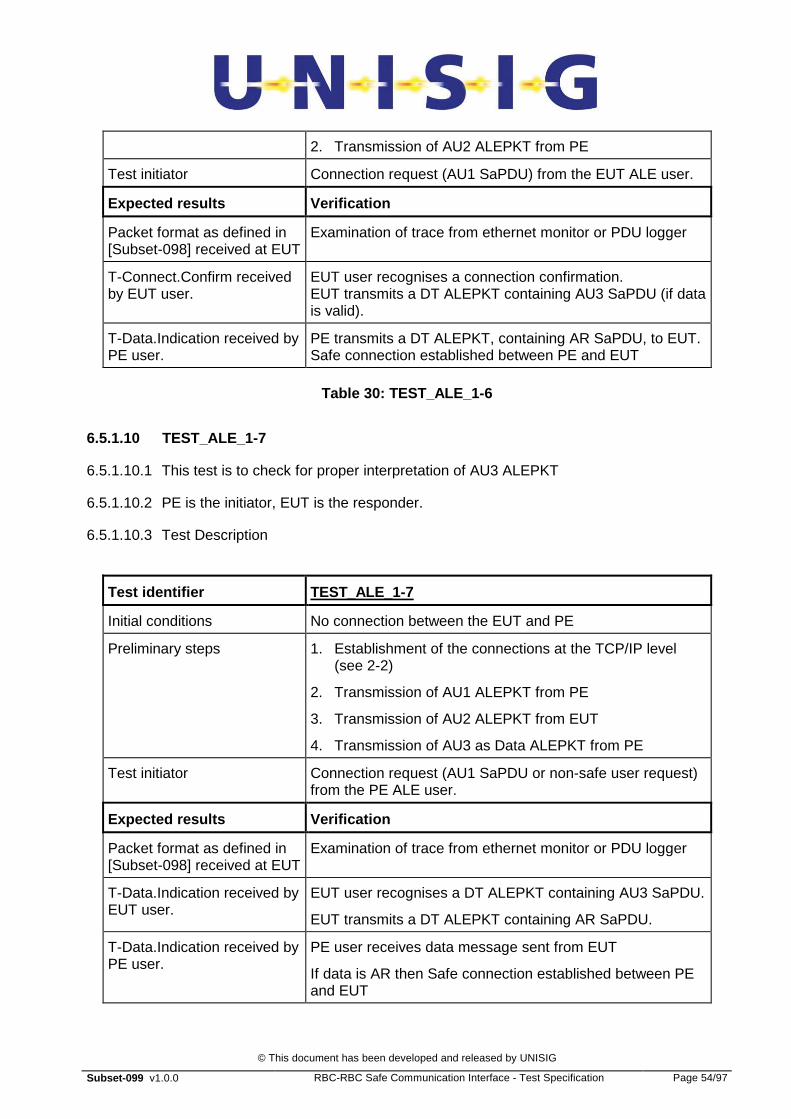
2. Transmission of AU2 ALEPKT from PE
Test initiator Connection request (AU1 SaPDU) from the EUT ALE user.
Expected results Verification
Packet format as defined in [Subset-098] received at EUT
Examination of trace from ethernet monitor or PDU logger
T-Connect.Confirm received by EUT user.
EUT user recognises a connection confirmation. EUT transmits a DT ALEPKT containing AU3 SaPDU (if data is valid).
T-Data.Indication received by PE user.
PE transmits a DT ALEPKT, containing AR SaPDU, to EUT. Safe connection established between PE and EUT
Table 30: TEST_ALE_1-6
6.5.1.10 TEST_ALE_1-7
6.5.1.10.1 This test is to check for proper interpretation of AU3 ALEPKT
6.5.1.10.2 PE is the initiator, EUT is the responder.
6.5.1.10.3 Test Description
Test identifier TEST_ALE_1-7
Initial conditions No connection between the EUT and PE
Preliminary steps 1. Establishment of the connections at the TCP/IP level (see 2-2)
2. Transmission of AU1 ALEPKT from PE
3. Transmission of AU2 ALEPKT from EUT
4. Transmission of AU3 as Data ALEPKT from PE
Test initiator Connection request (AU1 SaPDU or non-safe user request) from the PE ALE user.
Expected results Verification
Packet format as defined in [Subset-098] received at EUT
Examination of trace from ethernet monitor or PDU logger
T-Data.Indication received by EUT user.
EUT user recognises a DT ALEPKT containing AU3 SaPDU.
EUT transmits a DT ALEPKT containing AR SaPDU.
T-Data.Indication received by PE user.
PE user receives data message sent from EUT
If data is AR then Safe connection established between PE and EUT

© This document has been developed and released by UNISIG
Subset-099 v1.0.0 RBC-RBC Safe Communication Interface - Test Specification Page 55/97
Table 31: TEST_ALE_1-7
6.5.1.11 TEST_ALE_1-8
6.5.1.11.1 This test is to check for proper interpretation of Disc ALEPKT
6.5.1.11.2 EUT is the initiator, PE is the responder. PE is the disconnecting entity
6.5.1.11.3 Test Description
Test identifier TEST_ALE_1-8
Initial conditions Connection established between the EUT and PE
Preliminary steps 1. Establishment of the connections at the TCP/IP level (see TEST_ALE_2-2)
2. Establishment of safe connection between PE and EUT (see [Subset-098])
Test initiator T-Disconnect.Request (Disc SaPDU) received from the PE ALE user.
Expected results Verification
Packet format as defined in [SUBSET-098] 6.5.4.4 received at EUT
Examination of trace from ethernet monitor or PDU logger
T-Disconnect.Indication received by EUT user.
EUT user terminates safe connection TCP connections closed.
Table 32: TEST_ALE_1-8

© This document has been developed and released by UNISIG
Subset-099 v1.0.0 RBC-RBC Safe Communication Interface - Test Specification Page 56/97
6.5.2 TEST 2: ESTABLISH CLASS D CONNECTION
6.5.2.1 Test objective
6.5.2.1.1 The objective of these tests is to show that data are transferred in accordance with the definitions contained in Subset-098.
6.5.2.2 Test overview
6.5.2.2.1 Packets will be sent and received by the EUT during various types of activity such as connection establishment, connection release, data transfer and redundancy management. They can be captured by an ethernet monitor or PDU logger (as well as by the PE) to verify that they conform to the specification Subset-098
6.5.2.3 Traceability
Test Description Traceability with [Subset-098]
2.1 EUT listens for incoming TCP calls at configured addresses and accepts incoming Class D connection request.
6.5.2/6.6.2.1
2.2 EUT listens for incoming TCP calls at configured addresses and accepts incoming Class D connection request, only one TCP link being available.
6.5.2/6.6.2.1
2.3 EUT initiates Class D call, both TCP connections available
6.5.2/6.6.2.1
2.4 EUT initiates Class D call, one TCP connection unavailable
6.5.2/6.6.2.1
2.5 EUT initiates Class D call, both TCP connections unavailable
6.5.2/6.6.2.1
6.5.2.4 Network prerequisites
6.5.2.4.1 These tests should be conducted over physical connections that use at least two physical links (so that channels can be disturbed without losing layer 2 connections on the peer).
6.5.2.5 TEST_ALE_2-1
6.5.2.5.1 EUT listens for incoming TCP calls at configured addresses and accepts incoming Class D connection request.
6.5.2.5.2 Test Description
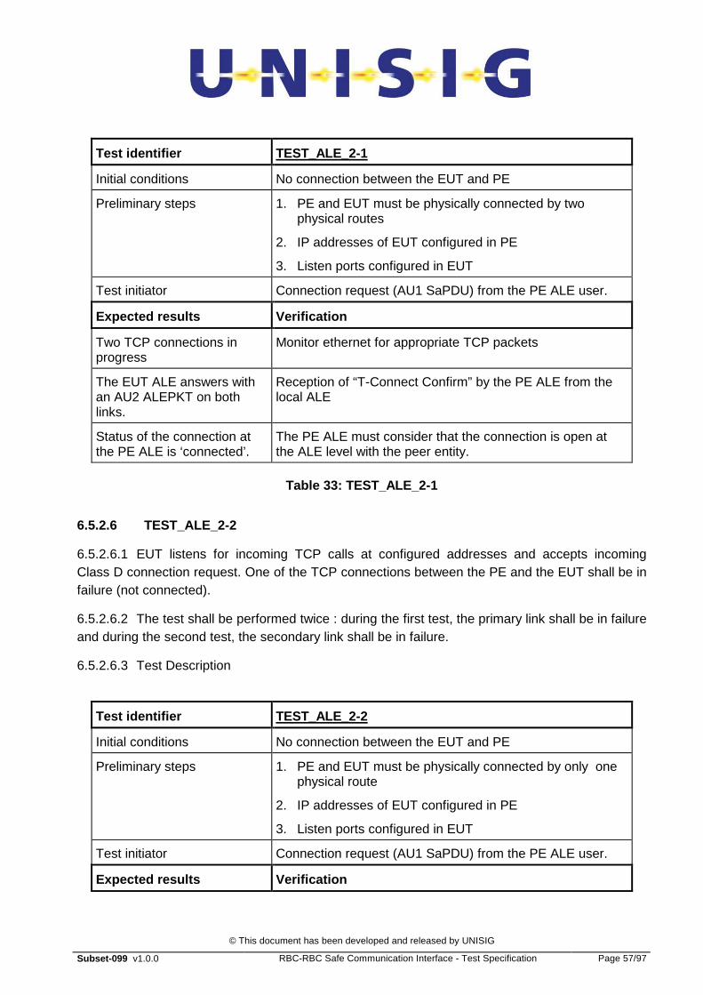
© This document has been developed and released by UNISIG
Subset-099 v1.0.0 RBC-RBC Safe Communication Interface - Test Specification Page 57/97
Test identifier TEST_ALE_2-1
Initial conditions No connection between the EUT and PE
Preliminary steps 1. PE and EUT must be physically connected by two physical routes
2. IP addresses of EUT configured in PE
3. Listen ports configured in EUT
Test initiator Connection request (AU1 SaPDU) from the PE ALE user.
Expected results Verification
Two TCP connections in progress
Monitor ethernet for appropriate TCP packets
The EUT ALE answers with an AU2 ALEPKT on both links.
Reception of “T-Connect Confirm” by the PE ALE from the local ALE
Status of the connection at the PE ALE is ‘connected’.
The PE ALE must consider that the connection is open at the ALE level with the peer entity.
Table 33: TEST_ALE_2-1
6.5.2.6 TEST_ALE_2-2
6.5.2.6.1 EUT listens for incoming TCP calls at configured addresses and accepts incoming Class D connection request. One of the TCP connections between the PE and the EUT shall be in failure (not connected).
6.5.2.6.2 The test shall be performed twice : during the first test, the primary link shall be in failure and during the second test, the secondary link shall be in failure.
6.5.2.6.3 Test Description
Test identifier TEST_ALE_2-2
Initial conditions No connection between the EUT and PE
Preliminary steps 1. PE and EUT must be physically connected by only one physical route
2. IP addresses of EUT configured in PE
3. Listen ports configured in EUT
Test initiator Connection request (AU1 SaPDU) from the PE ALE user.
Expected results Verification

© This document has been developed and released by UNISIG
Subset-099 v1.0.0 RBC-RBC Safe Communication Interface - Test Specification Page 58/97
Only one active TCP link Monitor ethernet for appropriate TCP packets
The EUT ALE answers with an AU2 ALEPKT on the active link.
Reception of “T-Connect Confirm” by the PE ALE from the local ALE
Status of the connection at the PE ALE is ‘connected’.
The PE ALE must consider that the connection is open at the ALE level with the peer entity.
Table 34: TEST_ALE_2-2
6.5.2.7 TEST_ALE_2-3
6.5.2.7.1 EUT initiates Class D call, both TCP connections available.
6.5.2.7.2 Test Description
Test identifier TEST_ALE_2-3
Initial conditions No connection between the EUT and PE
Preliminary steps 1. PE and EUT must be physically connected by two physical routes
2. IP addresses of PE configured in EUT
3. Listen ports configured in PE
Test initiator Connection request (AU1 SaPDU) from the EUT ALE user.
Expected results Verification
Two TCP connections started by EUT
Monitor ethernet for appropriate TCP packets
The PE ALE should answer with an AU2 ALEPKT on each TCP connection.
Reception of “T-Connect Confirm” by the EUT user from the local ALE
The EUT ALE must consider that the connection is opening with the peer entity.
Status of the connection at the EUT ALE level.
TransportSequenceNumber has value “0”
Monitor ethernet for appropriate TCP packets
Table 35: TEST_ALE_2-3
6.5.2.8 TEST_ALE_2-4
6.5.2.8.1 EUT initiates Class D call, one TCP connection unavailable.

© This document has been developed and released by UNISIG
Subset-099 v1.0.0 RBC-RBC Safe Communication Interface - Test Specification Page 59/97
6.5.2.8.2 The test shall be performed twice : during the first test, the primary link shall be not connected and during the second test, the secondary link shall be not connected.
6.5.2.8.3 Test Description
Test identifier TEST_ALE_2-4
Initial conditions No connection between the EUT and PE
Preliminary steps 1. PE and EUT must be physically connected by only one physical route (second route disabled)
2. IP addresses of PE configured in EUT
3. Listen ports configured in PE
4. One of PE ethernet ports is dis-connected.
Test initiator Connection request (AU1 SaPDU) from the EUT ALE user.
Expected results Verification
One TCP connection started by EUT
Monitor ethernet for appropriate TCP packets
The PE ALE should answer with an AU2 ALEPKT on the working TCP connection.
Reception of “T-Connect Confirm” by the EUT ALE from the local ALE
The EUT ALE must consider that the connection is open at the ALE level with the peer entity.
Status of the connection at the EUT ALE level.
TransportSequenceNumber has value “0”
Monitor ethernet for appropriate TCP packets on available TCP connection
Table 36: TEST_ALE_2-4
6.5.2.9 TEST_ALE_2-5
6.5.2.9.1 EUT initiates Class D call, both TCP connections unavailable.
6.5.2.9.2 Test Description
Test identifier TEST_ALE_2-5
Initial conditions No connection between the EUT and PE
Preliminary steps 1. PE and EUT must not be physically connected
2. IP addresses of PE configured in EUT
Test initiator Connection request (AU1 SaPDU) from the EUT ALE user.

© This document has been developed and released by UNISIG
Subset-099 v1.0.0 RBC-RBC Safe Communication Interface - Test Specification Page 60/97
Expected results Verification
EUT attempts to start both TCP connections.
Monitor ethernet for appropriate TCP packets from EUT and absence of reply packets from PE.
The EUT ALE should return a T-Disconnect.Indication
Reception of “T-Disconnect.Indication” by the EUT ALE user from the local ALE.
Table 37: TEST_ALE_2-5

© This document has been developed and released by UNISIG
Subset-099 v1.0.0 RBC-RBC Safe Communication Interface - Test Specification Page 61/97
6.5.3 TEST 3: DATA TRANSFER OVER A CLASS D CONNECTION
6.5.3.1 Test objective
6.5.3.1.1 The objective of these tests is to show that data are transferred in accordance with Subset-098.
6.5.3.2 Test overview
6.5.3.2.1 Packets will be sent and received by the EUT during various types of activity such as connection establishment, connection release, data transfer and redundancy management. They can be captured by an ethernet monitor or PDU logger (as well as by the PE) to verify that they conform to Subset-098.
6.5.3.3 Traceability
Test Description Traceability with [Subset-098]
3.1 Normal data transmission from EUT operates correctly using a Class D connection (with two TCP connections)
6.4.5/6.5.3/6.6.2.2
3.2 Data Transfer from EUT using a Class D connection works correctly with failure of one TCP connection
6.4.5/6.5.3/6.6.2.2
3.3 Value of TSeqNum is correctly incremented in each message transmitted by the EUT
6.4.5/6.5.3/6.6.2.2
6.5.3.4 Network prerequisites
6.5.3.4.1 These tests should be conducted over physical connections that use at least two physical links (so that channels can be disturbed without losing layer 2 connections on the peer).
6.5.3.5 TEST_3-1
6.5.3.5.1 Normal data transmission from the EUT operates correctly using a Class D connection (with two TCP connections).
6.5.3.5.2 Test Description
Test identifier TEST_ALE_3-1
Initial conditions No connection between the EUT and PE

© This document has been developed and released by UNISIG
Subset-099 v1.0.0 RBC-RBC Safe Communication Interface - Test Specification Page 62/97
Preliminary steps 1. PE and EUT must be physically connected by two physical routes
2. IP addresses of PE configured in EUT
3. Listen addresses configured in PE
4. Establishment of the connection at the TCP/IP level by EUT
5. Establishment of the connection at the ALE level
6. Exchange of the AU 1 ALEPKT, AU2 ALEPKT.
Test initiator DT ALEPKT, containing AU3 SaPDU, sent by EUT
Expected results Verification
- Data ALEPKTs sent on both TCP connections.
Monitor ethernets for appropriate TCP packets
Table 38: TEST_ALE_3-1
6.5.3.6 TEST_ALE_3-2
6.5.3.6.1 Data Transfer from EUT using a Class D connection works correctly with failure of one TCP connection.
6.5.3.6.2 The test shall be performed twice : during the first test, the primary link shall be not connected and during the second test, the secondary link shall be not connected.
6.5.3.6.3 Test Description
Test identifier TEST_ALE_3-2
Initial conditions No connection between the EUT and PE
Preliminary steps 1. PE and EUT must be initially connected by two physical routes
2. IP addresses of PE configured in EUT
3. Listen addresses configured in PE
4. Establishment of the connection at the TCP/IP level by EUT
5. Establishment of the connection at the ALE level
6. Exchange of the AU 1 ALEPKT, AU2 ALEPKT.
7. Start data transfer
Test initiator With data transfer in normal operation disconnect one ethernet at PE.
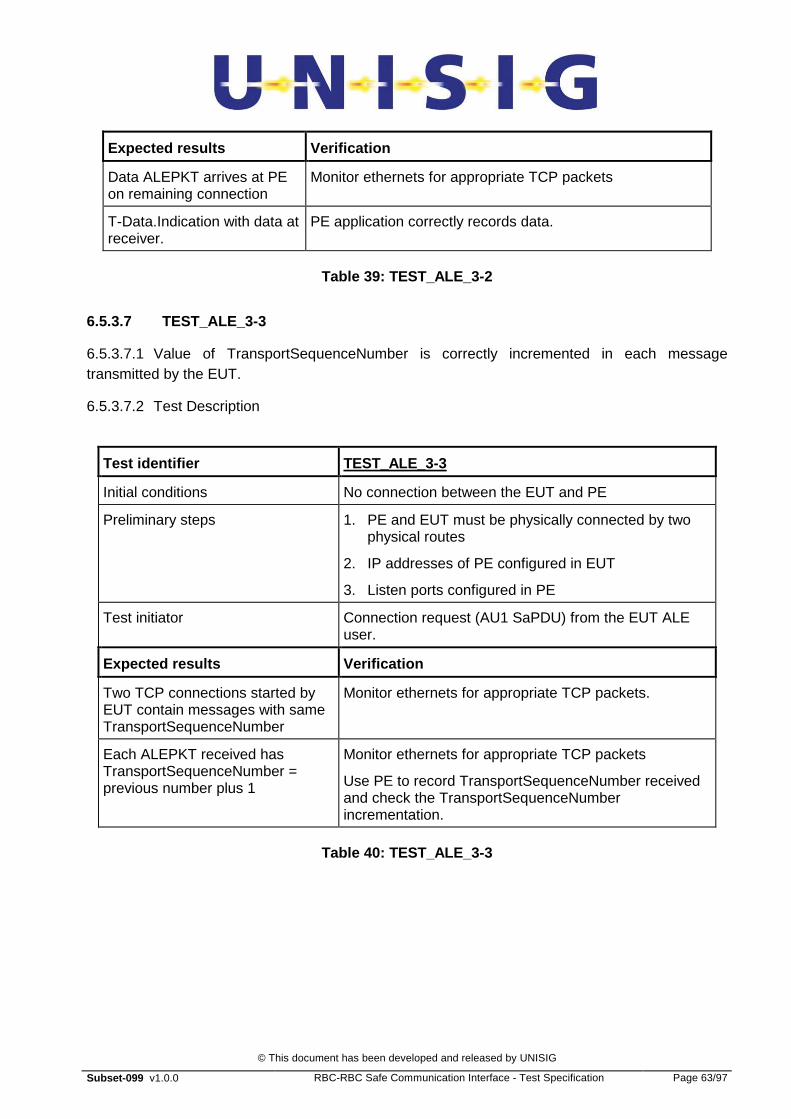
© This document has been developed and released by UNISIG
Subset-099 v1.0.0 RBC-RBC Safe Communication Interface - Test Specification Page 63/97
Expected results Verification
Data ALEPKT arrives at PE on remaining connection
Monitor ethernets for appropriate TCP packets
T-Data.Indication with data at receiver.
PE application correctly records data.
Table 39: TEST_ALE_3-2
6.5.3.7 TEST_ALE_3-3
6.5.3.7.1 Value of TransportSequenceNumber is correctly incremented in each message transmitted by the EUT.
6.5.3.7.2 Test Description
Test identifier TEST_ALE_3-3
Initial conditions No connection between the EUT and PE
Preliminary steps 1. PE and EUT must be physically connected by two physical routes
2. IP addresses of PE configured in EUT
3. Listen ports configured in PE
Test initiator Connection request (AU1 SaPDU) from the EUT ALE user.
Expected results Verification
Two TCP connections started by EUT contain messages with same TransportSequenceNumber
Monitor ethernets for appropriate TCP packets.
Each ALEPKT received has TransportSequenceNumber = previous number plus 1
Monitor ethernets for appropriate TCP packets
Use PE to record TransportSequenceNumber received and check the TransportSequenceNumber incrementation.
Table 40: TEST_ALE_3-3

© This document has been developed and released by UNISIG
Subset-099 v1.0.0 RBC-RBC Safe Communication Interface - Test Specification Page 64/97
6.5.4 TEST 4: RELEASE OF A CLASS D CONNECTION
6.5.4.1 Test objective
6.5.4.1.1 The purpose of these tests is to demonstrate that the EUT ALE correctly handles all conditions that cause disconnection from the peer.
6.5.4.2 Test overview
6.5.4.2.1 Packets will be sent and received by the EUT during various types of activity such as connection establishment, connection release, data transfer and redundancy management. They can be captured by an ethernet monitor or PDU logger (as well as by the PE) to verify that they conform to Subset-098.
6.5.4.3 Scenarios and Traceability
Test Description Traceability with [Subset-098]
4.1 Normal release of Class D connection (with two TCP connections) by initiator (EUT)
6.5.4/6.6.2
4.2 Correct reaction by responder to normal release of Class D connection (with two TCP connections).
6.5.4/6.6.2
4.3 Normal release of Class D connection with one TCP connection already in failure
6.5.4/6.6.2
4.4 Normal release of Class D connection with one TCP connection already in failure initiated by EUT
6.5.4/6.6.2
4.5 Release due to failure of both TCP connections (e.g. remote peer failure)
6.5.4/6.6.2
6.5.4.4 Network prerequisites
6.5.4.4.1 These tests should be conducted over physical connections that use at least two physical links (so that channels can be disturbed without losing layer 2 connections on the peer).
6.5.4.5 TEST_ALE_4-1
6.5.4.5.1 Ensure that Normal release of Class D connection (with two TCP connections) by initiator (EUT) works correctly.
6.5.4.5.2 Test Description

© This document has been developed and released by UNISIG
Subset-099 v1.0.0 RBC-RBC Safe Communication Interface - Test Specification Page 65/97
Test identifier TEST_ALE_4-1
Initial conditions No connection between RBC’s.
Preliminary steps 1. PE and EUT must be physically connected by two physical routes
2. IP addresses of PE configured in EUT
3. Listen addresses configured in PE
4. Establishment of the connections at the TCP/IP level by EUT
5. Establishment of the connection at the ALE level
6. Establishment of safe connection
7. Continuous data transfer.
Test initiator Disc SaPDU received from local user by EUT ALE.
Expected results Verification
Release of the connection. All data delivered on both sides.
DI ALEPKT delivered on PE.
Release of TCP connections.
ALE User connection closed Safe connection terminated.
Table 41: TEST_ALE_4-1
6.5.4.6 TEST_ALE_4-2
6.5.4.6.1 Correct reaction by responder (EUT) to normal release of Class D connection (with two TCP connections).
6.5.4.6.2 Test Description
Test identifier TEST_ALE_4-2
Initial conditions No connection between RBC’s.
Preliminary steps 1. PE and EUT must be physically connected by two physical routes
2. IP addresses of PE configured in EUT
3. Listen addresses configured in PE
4. Establishment of the connections at the TCP/IP level by EUT
5. Establishment of the connection at the ALE level
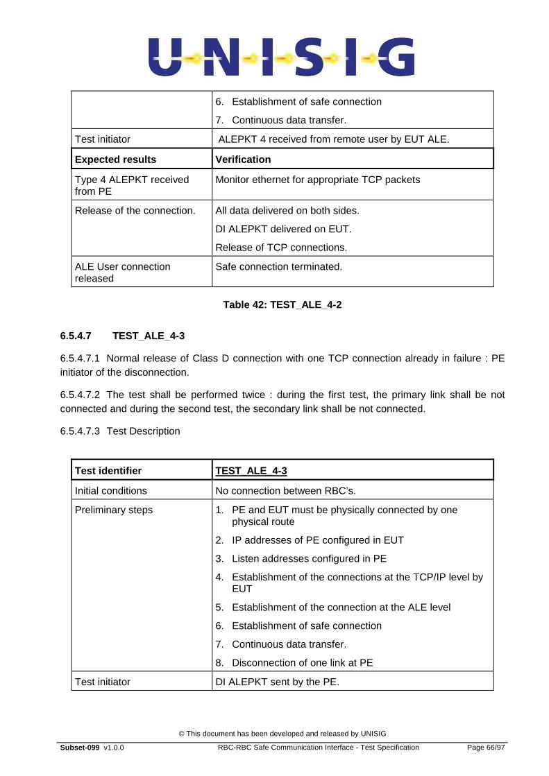
© This document has been developed and released by UNISIG
Subset-099 v1.0.0 RBC-RBC Safe Communication Interface - Test Specification Page 66/97
6. Establishment of safe connection
7. Continuous data transfer.
Test initiator ALEPKT 4 received from remote user by EUT ALE.
Expected results Verification
Type 4 ALEPKT received from PE
Monitor ethernet for appropriate TCP packets
Release of the connection. All data delivered on both sides.
DI ALEPKT delivered on EUT.
Release of TCP connections.
ALE User connection released
Safe connection terminated.
Table 42: TEST_ALE_4-2
6.5.4.7 TEST_ALE_4-3
6.5.4.7.1 Normal release of Class D connection with one TCP connection already in failure : PE initiator of the disconnection.
6.5.4.7.2 The test shall be performed twice : during the first test, the primary link shall be not connected and during the second test, the secondary link shall be not connected.
6.5.4.7.3 Test Description
Test identifier TEST_ALE_4-3
Initial conditions No connection between RBC’s.
Preliminary steps 1. PE and EUT must be physically connected by one physical route
2. IP addresses of PE configured in EUT
3. Listen addresses configured in PE
4. Establishment of the connections at the TCP/IP level by EUT
5. Establishment of the connection at the ALE level
6. Establishment of safe connection
7. Continuous data transfer.
8. Disconnection of one link at PE
Test initiator DI ALEPKT sent by the PE.
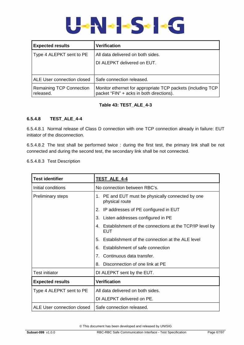
© This document has been developed and released by UNISIG
Subset-099 v1.0.0 RBC-RBC Safe Communication Interface - Test Specification Page 67/97
Expected results Verification
Type 4 ALEPKT sent to PE All data delivered on both sides.
DI ALEPKT delivered on EUT.
ALE User connection closed Safe connection released.
Remaining TCP Connection released.
Monitor ethernet for appropriate TCP packets (including TCP packet “FIN” + acks in both directions).
Table 43: TEST_ALE_4-3
6.5.4.8 TEST_ALE_4-4
6.5.4.8.1 Normal release of Class D connection with one TCP connection already in failure: EUT initiator of the disconnection.
6.5.4.8.2 The test shall be performed twice : during the first test, the primary link shall be not connected and during the second test, the secondary link shall be not connected.
6.5.4.8.3 Test Description
Test identifier TEST_ALE_4-4
Initial conditions No connection between RBC’s.
Preliminary steps 1. PE and EUT must be physically connected by one physical route
2. IP addresses of PE configured in EUT
3. Listen addresses configured in PE
4. Establishment of the connections at the TCP/IP level by EUT
5. Establishment of the connection at the ALE level
6. Establishment of safe connection
7. Continuous data transfer.
8. Disconnection of one link at PE
Test initiator DI ALEPKT sent by the EUT.
Expected results Verification
Type 4 ALEPKT sent to PE All data delivered on both sides.
DI ALEPKT delivered on PE.
ALE User connection closed Safe connection released.

© This document has been developed and released by UNISIG
Subset-099 v1.0.0 RBC-RBC Safe Communication Interface - Test Specification Page 68/97
Remaining TCP Connection released.
Monitor ethernet for appropriate TCP packets (including TCP packet “FIN” + acks in both directions).
Table 44: TEST_ALE_4-4
6.5.4.9 TEST_4-5
6.5.4.9.1 Release due to failure of both TCP connections (e.g. remote peer failure).
6.5.4.9.2 Test Description
Test identifier TEST_ALE_4-5
Initial conditions No connection between RBC’s.
Preliminary steps 1. PE and EUT must be physically connected by two physical routes
2. IP addresses of PE configured in EUT
3. Listen addresses configured in PE
4. Establishment of the connections at the TCP/IP level by EUT
5. Establishment of the connection at the ALE level
6. Establishment of safe connection
7. Continuous data transfer.
Test initiator Power off PE or remove both links from PE
Expected results Verification
TCP Connections closed when error detected
ALE abandons TCP connections (abort)
T_Disconnect.Indication sent to local ALE user
Status of connection changes (to closed).
Table 45: TEST_ALE_4-5
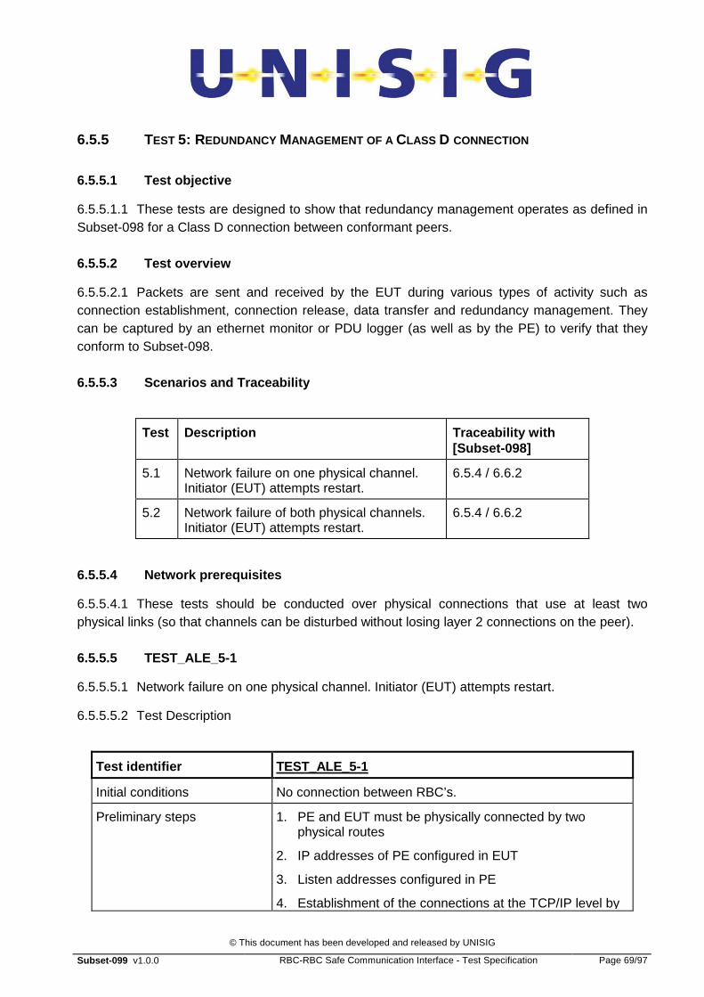
© This document has been developed and released by UNISIG
Subset-099 v1.0.0 RBC-RBC Safe Communication Interface - Test Specification Page 69/97
6.5.5 TEST 5: REDUNDANCY MANAGEMENT OF A CLASS D CONNECTION
6.5.5.1 Test objective
6.5.5.1.1 These tests are designed to show that redundancy management operates as defined in Subset-098 for a Class D connection between conformant peers.
6.5.5.2 Test overview
6.5.5.2.1 Packets are sent and received by the EUT during various types of activity such as connection establishment, connection release, data transfer and redundancy management. They can be captured by an ethernet monitor or PDU logger (as well as by the PE) to verify that they conform to Subset-098.
6.5.5.3 Scenarios and Traceability
Test Description Traceability with [Subset-098]
5.1 Network failure on one physical channel. Initiator (EUT) attempts restart.
6.5.4 / 6.6.2
5.2 Network failure of both physical channels. Initiator (EUT) attempts restart.
6.5.4 / 6.6.2
6.5.5.4 Network prerequisites
6.5.5.4.1 These tests should be conducted over physical connections that use at least two physical links (so that channels can be disturbed without losing layer 2 connections on the peer).
6.5.5.5 TEST_ALE_5-1
6.5.5.5.1 Network failure on one physical channel. Initiator (EUT) attempts restart.
6.5.5.5.2 Test Description
Test identifier TEST_ALE_5-1
Initial conditions No connection between RBC’s.
Preliminary steps 1. PE and EUT must be physically connected by two physical routes
2. IP addresses of PE configured in EUT
3. Listen addresses configured in PE
4. Establishment of the connections at the TCP/IP level by

© This document has been developed and released by UNISIG
Subset-099 v1.0.0 RBC-RBC Safe Communication Interface - Test Specification Page 70/97
EUT
5. Establishment of the connection at the ALE level
6. Establishment of safe connection
7. Continuous data transfer.
Test initiator One of the physical routes temporarily disrupted (until TCP failure).
Expected results Verification
EUT recognises loss of TCP connection.
Timer expiry causes reset of TCP connection.
Data flow continues on remaining channel.
All the expected data are correctly received by both peers. Monitor ethernet for appropriate TCP packets
EUT restarts TCP connection, PE accepts re-connection, data transfer restarts.
Monitor ethernet for appropriate TCP packets
Table 46: TEST_ALE_5-1
6.5.5.6 TEST_ALE_5-2
6.5.5.6.1 Network failure of both physical channels. Initiator (PE) attempts restart.
6.5.5.6.2 Test Description
Test identifier TEST_ALE_5-2
Initial conditions No connection between RBC’s..
Preliminary steps 1. PE and EUT must be physically connected by two physical routes
2. IP addresses of PE configured in EUT
3. Listen addresses configured in PE
4. Establishment of the connections at the TCP/IP level by EUT
5. Establishment of the connection at the ALE level
6. Establishment of safe connection
7. Continuous data transfer.
Test initiator Both of the physical routes temporarily disrupted (until TCP failure).
Expected results Verification

© This document has been developed and released by UNISIG
Subset-099 v1.0.0 RBC-RBC Safe Communication Interface - Test Specification Page 71/97
EUT recognises loss of both TCP connections.
Safe connection released at both peers (but particularly EUT).
PE restarts TCP connections, EUT accepts re-connection, data transfer restarts.
Monitor ethernet for appropriate TCP packets
Table 47: TEST_ALE_5-2
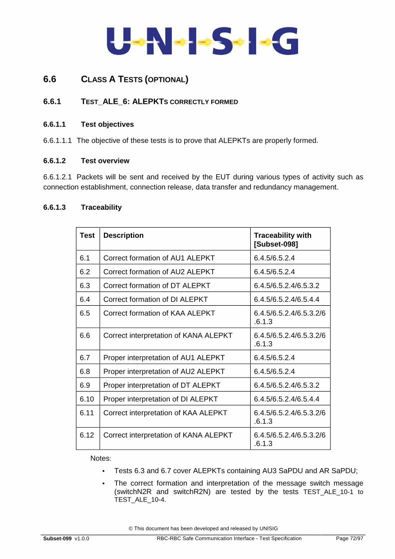
© This document has been developed and released by UNISIG
Subset-099 v1.0.0 RBC-RBC Safe Communication Interface - Test Specification Page 72/97
6.6 CLASS A TESTS (OPTIONAL)
6.6.1 TEST_ALE_6: ALEPKT S CORRECTLY FORMED
6.6.1.1 Test objectives
6.6.1.1.1 The objective of these tests is to prove that ALEPKTs are properly formed.
6.6.1.2 Test overview
6.6.1.2.1 Packets will be sent and received by the EUT during various types of activity such as connection establishment, connection release, data transfer and redundancy management.
6.6.1.3 Traceability
Test Description Traceability with [Subset-098]
6.1 Correct formation of AU1 ALEPKT 6.4.5/6.5.2.4
6.2 Correct formation of AU2 ALEPKT 6.4.5/6.5.2.4
6.3 Correct formation of DT ALEPKT 6.4.5/6.5.2.4/6.5.3.2
6.4 Correct formation of DI ALEPKT 6.4.5/6.5.2.4/6.5.4.4
6.5 Correct formation of KAA ALEPKT 6.4.5/6.5.2.4/6.5.3.2/6.6.1.3
6.6 Correct interpretation of KANA ALEPKT 6.4.5/6.5.2.4/6.5.3.2/6.6.1.3
6.7 Proper interpretation of AU1 ALEPKT 6.4.5/6.5.2.4
6.8 Proper interpretation of AU2 ALEPKT 6.4.5/6.5.2.4
6.9 Proper interpretation of DT ALEPKT 6.4.5/6.5.2.4/6.5.3.2
6.10 Proper interpretation of DI ALEPKT 6.4.5/6.5.2.4/6.5.4.4
6.11 Correct interpretation of KAA ALEPKT 6.4.5/6.5.2.4/6.5.3.2/6.6.1.3
6.12 Correct interpretation of KANA ALEPKT 6.4.5/6.5.2.4/6.5.3.2/6.6.1.3
Notes:
• Tests 6.3 and 6.7 cover ALEPKTs containing AU3 SaPDU and AR SaPDU;
• The correct formation and interpretation of the message switch message (switchN2R and switchR2N) are tested by the tests TEST_ALE_10-1 to TEST_ALE_10-4.

© This document has been developed and released by UNISIG
Subset-099 v1.0.0 RBC-RBC Safe Communication Interface - Test Specification Page 73/97
6.6.1.4 TEST_ALE_6-1
6.6.1.4.1 The objective of this test is to ensure correct formation of AU1 ALEPKT.
6.6.1.4.2 EUT is the initiator, PE is the responder.
6.6.1.4.3 Test Description
Test identifier TEST_ALE_6-1
Initial conditions No connection between the EUT and PE
Preliminary steps • Establishment of the connections at the TCP/IP level
Test initiator Connection request (AU1 SaPDU) from the EUT ALE user.
Expected results Verification
AU1 ALEPKT format as defined in [Subset-098]
Examination of trace from ethernet monitor or PDU logger
Connection request recognised by PE.
The PE user shall receive a “T-Connect indication”.
Reception by the EUT user of “T-Connect Confirm” from the ALE.
Note : The AU1 and AU2 ALEPKT’s are exchanged on the active link only.
Table 48: TEST_ALE_6-1
6.6.1.5 TEST_ALE_6-2
6.6.1.5.1 The objective of this test is to ensure correct formation of AU2 ALEPKT
6.6.1.5.2 PE is the initiator, EUT is the responder
6.6.1.5.3 Test Description
Test identifier TEST_ALE_6-2
Initial conditions No connection between the EUT and PE
Preliminary steps • Establishment of the connections at the TCP/IP level by PE.
• Receipt of T-Connect.Indication from EUT ALE
Test initiator Connection request (AU1 SaPDU) from the PE ALE user.
Expected results Verification
AU2 ALEPKT format as defined in [Subset-098]
Examination of trace from ethernet monitor or PDU logger

© This document has been developed and released by UNISIG
Subset-099 v1.0.0 RBC-RBC Safe Communication Interface - Test Specification Page 74/97
T-Connect.Confirm received by PE user.
EUT user recognises a valid connection attempt
EUT transmits a AU2 ALEPKT
PE transmits AU3 as DT ALEPKT.
Note : The AU1, AU2 and DT ALEPKT’s are exchanged on the active link only.
Table 49: TEST_ALE_6-2
6.6.1.6 TEST_ALE_6-3
6.6.1.6.1 The objective of this test is to ensure correct formation of Data ALEPKT containing AU3 SaPDU.
6.6.1.6.2 EUT is the initiator, PE is the responder
6.6.1.6.3 Test Description
Test identifier TEST_ALE 6-3
Initial conditions No connection between the EUT and PE
Preliminary steps • Establishment of the connections at the TCP/IP level
• Receipt by EUT user of T-Connect.Confirm from EUT ALE
Test initiator Connection request (AU1 SaPDU) from the EUT ALE user.
Expected results Verification
Data ALEPKT containing AU3 transmitted by EUT. Packet format as defined in [Subset-098]
Examination of trace from ethernet monitor or PDU logger
The PE user shall receive a “T-Data.Indication” with AU3 SaPDU.
Data recognised by PE (AU3 SaPDU).
Reception by the EUT user of AR SaPDU in DT ALEPKT from the PE .
Note : The AU1, AU2 and DT ALEPKT’s are exchanged on the active link only.
Table 50: TEST_ALE_6-3
6.6.1.7 TEST_ALE_6-4
6.6.1.7.1 The objective of this test is to ensure correct formation of DI ALEPKT
6.6.1.7.2 EUT is the initiator, PE is the responder. EUT is the disconnecting entity.
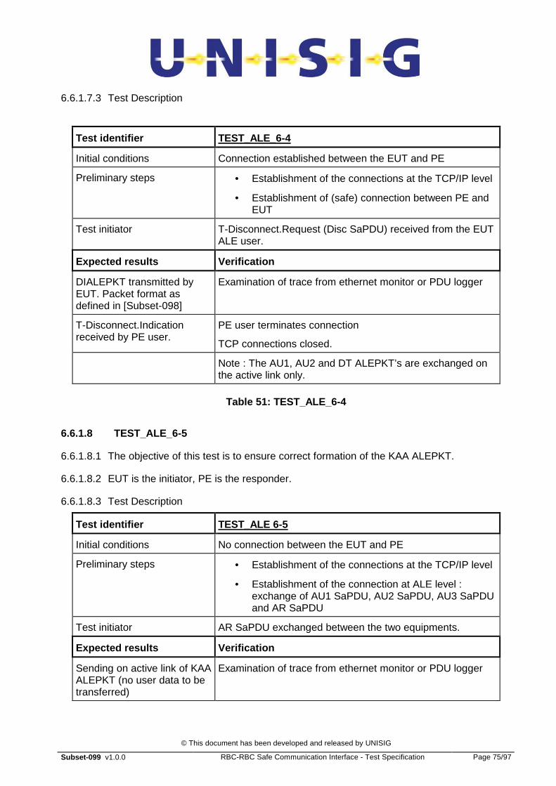
© This document has been developed and released by UNISIG
Subset-099 v1.0.0 RBC-RBC Safe Communication Interface - Test Specification Page 75/97
6.6.1.7.3 Test Description
Test identifier TEST_ALE_6-4
Initial conditions Connection established between the EUT and PE
Preliminary steps • Establishment of the connections at the TCP/IP level
• Establishment of (safe) connection between PE and EUT
Test initiator T-Disconnect.Request (Disc SaPDU) received from the EUT ALE user.
Expected results Verification
DIALEPKT transmitted by EUT. Packet format as defined in [Subset-098]
Examination of trace from ethernet monitor or PDU logger
T-Disconnect.Indication received by PE user.
PE user terminates connection
TCP connections closed.
Note : The AU1, AU2 and DT ALEPKT’s are exchanged on the active link only.
Table 51: TEST_ALE_6-4
6.6.1.8 TEST_ALE_6-5
6.6.1.8.1 The objective of this test is to ensure correct formation of the KAA ALEPKT.
6.6.1.8.2 EUT is the initiator, PE is the responder.
6.6.1.8.3 Test Description
Test identifier TEST_ALE 6-5
Initial conditions No connection between the EUT and PE
Preliminary steps • Establishment of the connections at the TCP/IP level
• Establishment of the connection at ALE level : exchange of AU1 SaPDU, AU2 SaPDU, AU3 SaPDU and AR SaPDU
Test initiator AR SaPDU exchanged between the two equipments.
Expected results Verification
Sending on active link of KAA ALEPKT (no user data to be transferred)
Examination of trace from ethernet monitor or PDU logger

© This document has been developed and released by UNISIG
Subset-099 v1.0.0 RBC-RBC Safe Communication Interface - Test Specification Page 76/97
The PE user shall receive the KAA ALEPKT.
Examination of trace from ethernet monitor or PDU logger
Note : The KAA ALEPKT’s are exchanged on the active link only.
Table 52: TEST_ALE_6-5
6.6.1.9 TEST_ALE_6-6
6.6.1.9.1 The objective of this test is to ensure correct formation of the KANA ALEPKT.
6.6.1.9.2 EUT is the initiator, PE is the responder.
6.6.1.9.3 Test Description
Test identifier TEST_ALE 6-6
Initial conditions No connection between the EUT and PE
Preliminary steps • Establishment of the connections at the TCP/IP level
• Establishment of the connection at ALE level : exchange of AU1 SaPDU, AU2 SaPDU, AU3 SaPDU and AR SaPDU
Test initiator AR SaPDU exchanged between the two equipments.
Expected results Verification
Sending, on non-active link, of KANA ALEPKT
Examination of trace from ethernet monitor or PDU logger
The PE user shall receive the KANA ALEPKT.
Examination of trace from ethernet monitor or PDU logger
Note : The KANA ALEPKT’s are exchanged on the non-active link only.
Table 53: TEST_ALE_6-6
6.6.1.10 TEST_ALE_6-7
6.6.1.10.1 This test is to check for proper interpretation of AU1 ALEPKT
6.6.1.10.2 PE is the initiator, EUT is the responder
6.6.1.10.3 Test Description
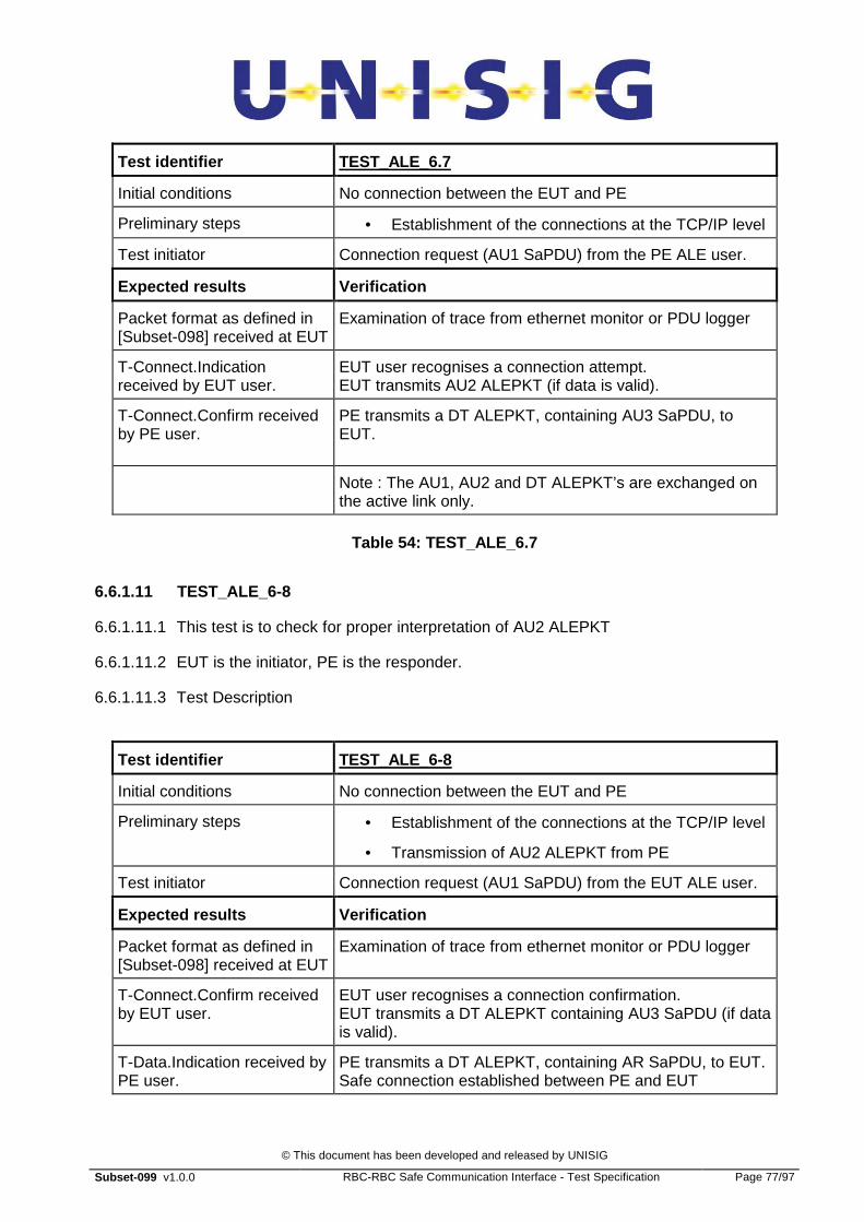
© This document has been developed and released by UNISIG
Subset-099 v1.0.0 RBC-RBC Safe Communication Interface - Test Specification Page 77/97
Test identifier TEST_ALE_6.7
Initial conditions No connection between the EUT and PE
Preliminary steps • Establishment of the connections at the TCP/IP level
Test initiator Connection request (AU1 SaPDU) from the PE ALE user.
Expected results Verification
Packet format as defined in [Subset-098] received at EUT
Examination of trace from ethernet monitor or PDU logger
T-Connect.Indication received by EUT user.
EUT user recognises a connection attempt. EUT transmits AU2 ALEPKT (if data is valid).
T-Connect.Confirm received by PE user.
PE transmits a DT ALEPKT, containing AU3 SaPDU, to EUT.
Note : The AU1, AU2 and DT ALEPKT’s are exchanged on the active link only.
Table 54: TEST_ALE_6.7
6.6.1.11 TEST_ALE_6-8
6.6.1.11.1 This test is to check for proper interpretation of AU2 ALEPKT
6.6.1.11.2 EUT is the initiator, PE is the responder.
6.6.1.11.3 Test Description
Test identifier TEST_ALE_6-8
Initial conditions No connection between the EUT and PE
Preliminary steps • Establishment of the connections at the TCP/IP level
• Transmission of AU2 ALEPKT from PE
Test initiator Connection request (AU1 SaPDU) from the EUT ALE user.
Expected results Verification
Packet format as defined in [Subset-098] received at EUT
Examination of trace from ethernet monitor or PDU logger
T-Connect.Confirm received by EUT user.
EUT user recognises a connection confirmation. EUT transmits a DT ALEPKT containing AU3 SaPDU (if data is valid).
T-Data.Indication received by PE user.
PE transmits a DT ALEPKT, containing AR SaPDU, to EUT. Safe connection established between PE and EUT

© This document has been developed and released by UNISIG
Subset-099 v1.0.0 RBC-RBC Safe Communication Interface - Test Specification Page 78/97
Note : The AU1, AU2 and DT ALEPKT’s are exchanged on the active link only.
Table 55: TEST_ALE_6.8
6.6.1.12 TEST_ALE_6-9
6.6.1.12.1 This test is to check for proper interpretation of AU3 ALEPKT
6.6.1.12.2 PE is the initiator, EUT is the responder.
6.6.1.12.3 Test Description
Test identifier TEST_ALE_6-9
Initial conditions No connection between the EUT and PE
Preliminary steps • Establishment of the connections at the TCP/IP level
• Transmission of AU1 ALEPKT from PE
• Transmission of AU2 ALEPKT from EUT
• Transmission of AU3 as Data ALEPKT from PE
Test initiator Connection request (AU1 SaPDU or non-safe user request) from the PE ALE user.
Expected results Verification
Packet format as defined in [Subset-098] received at EUT
Examination of trace from ethernet monitor or PDU logger
T-Data.Indication received by EUT user.
EUT user recognises a DT ALEPKT containing AU3 SaPDU.
EUT transmits a DT ALEPKT containing AR SaPDU.
T-Data.Indication received by PE user.
PE user receives data message sent from EUT
If data is AR then Safe connection established between PE and EUT
Note : The AU1, AU2 and DT ALEPKT’s are exchanged on the active link only.
Table 56: TEST_ALE_6.9
6.6.1.13 TEST_ALE_6-10
6.6.1.13.1 This test is to check for proper interpretation of Disc ALEPKT
6.6.1.13.2 EUT is the initiator, PE is the responder. PE is the disconnecting entity
6.6.1.13.3 Test Description
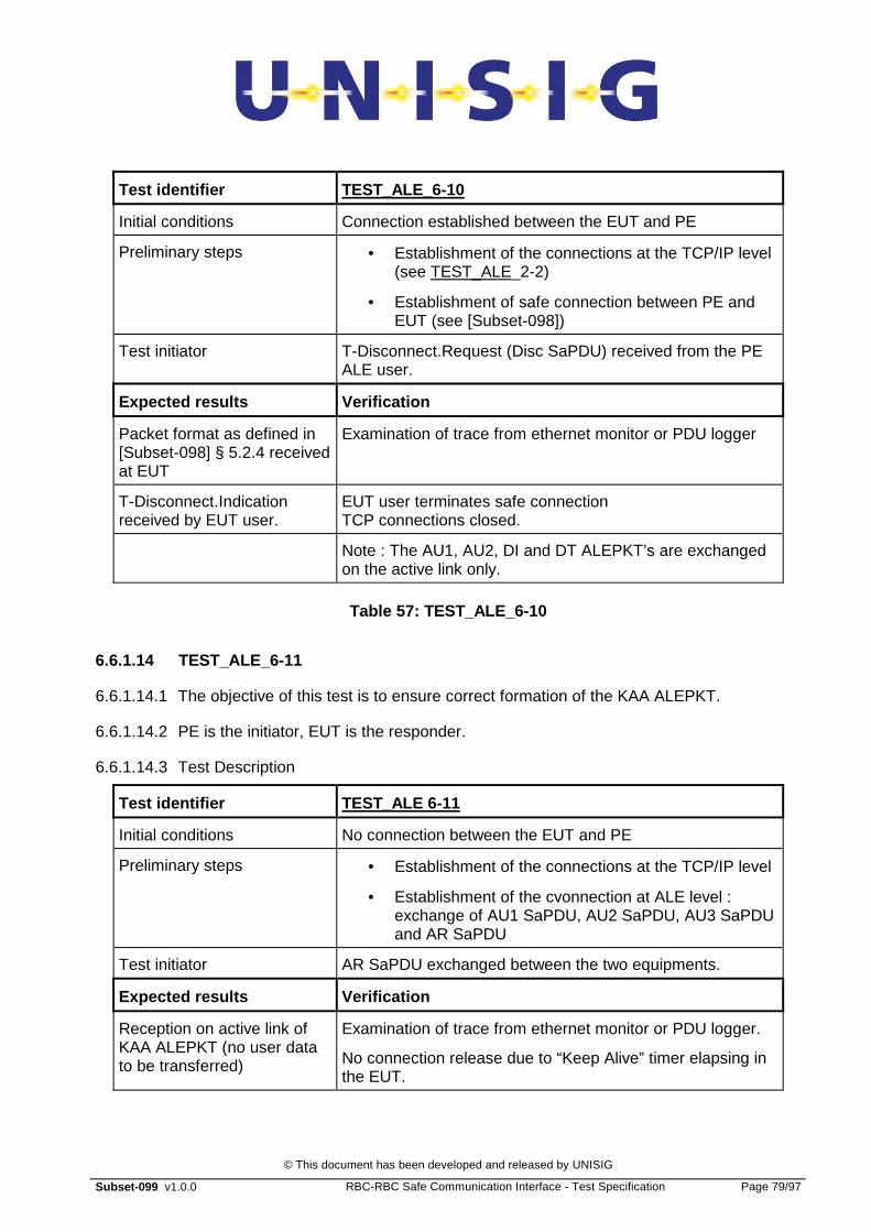
© This document has been developed and released by UNISIG
Subset-099 v1.0.0 RBC-RBC Safe Communication Interface - Test Specification Page 79/97
Test identifier TEST_ALE_6-10
Initial conditions Connection established between the EUT and PE
Preliminary steps • Establishment of the connections at the TCP/IP level (see TEST_ALE_2-2)
• Establishment of safe connection between PE and EUT (see [Subset-098])
Test initiator T-Disconnect.Request (Disc SaPDU) received from the PE ALE user.
Expected results Verification
Packet format as defined in [Subset-098] § 5.2.4 received at EUT
Examination of trace from ethernet monitor or PDU logger
T-Disconnect.Indication received by EUT user.
EUT user terminates safe connection TCP connections closed.
Note : The AU1, AU2, DI and DT ALEPKT’s are exchanged on the active link only.
Table 57: TEST_ALE_6-10
6.6.1.14 TEST_ALE_6-11
6.6.1.14.1 The objective of this test is to ensure correct formation of the KAA ALEPKT.
6.6.1.14.2 PE is the initiator, EUT is the responder.
6.6.1.14.3 Test Description
Test identifier TEST_ALE 6-11
Initial conditions No connection between the EUT and PE
Preliminary steps • Establishment of the connections at the TCP/IP level
• Establishment of the cvonnection at ALE level : exchange of AU1 SaPDU, AU2 SaPDU, AU3 SaPDU and AR SaPDU
Test initiator AR SaPDU exchanged between the two equipments.
Expected results Verification
Reception on active link of KAA ALEPKT (no user data to be transferred)
Examination of trace from ethernet monitor or PDU logger.
No connection release due to “Keep Alive” timer elapsing in the EUT.
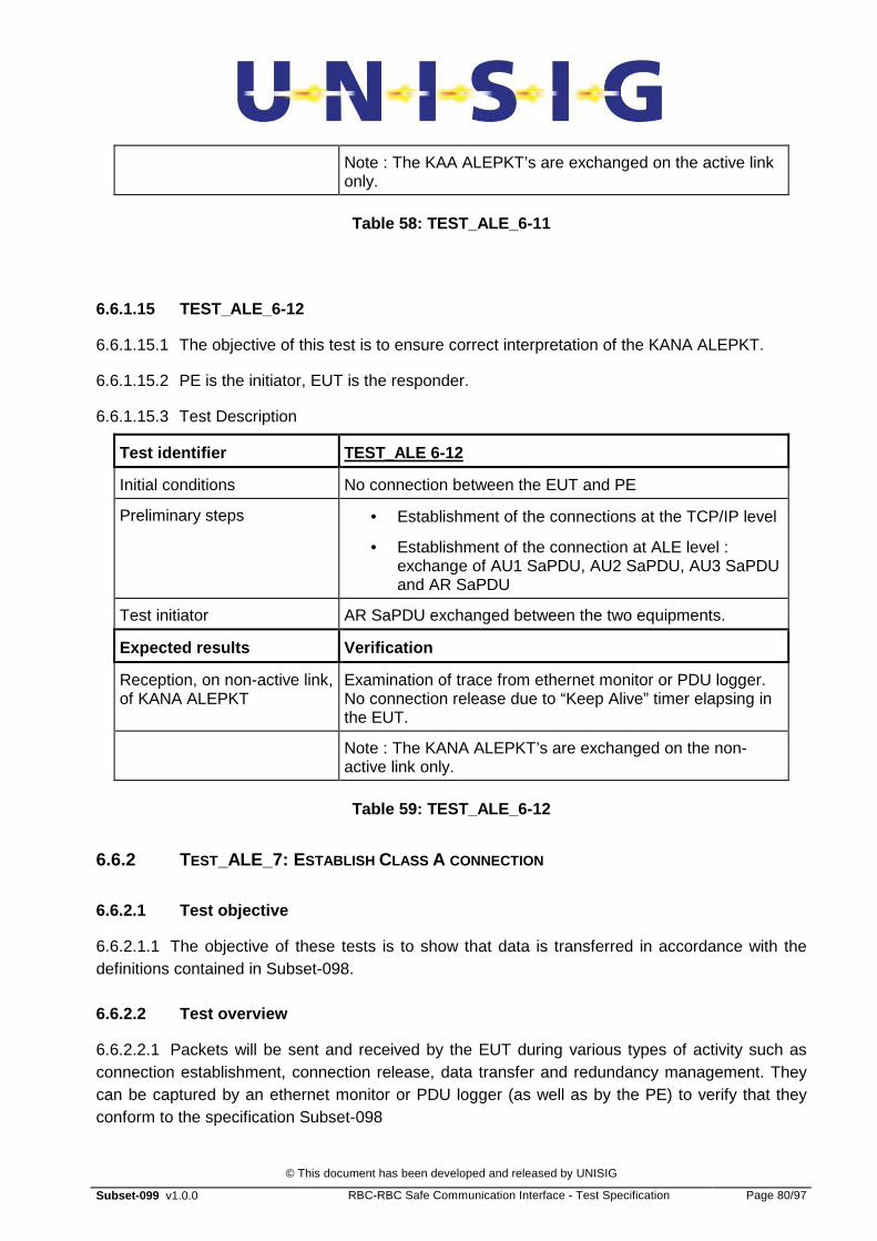
© This document has been developed and released by UNISIG
Subset-099 v1.0.0 RBC-RBC Safe Communication Interface - Test Specification Page 80/97
Note : The KAA ALEPKT’s are exchanged on the active link only.
Table 58: TEST_ALE_6-11
6.6.1.15 TEST_ALE_6-12
6.6.1.15.1 The objective of this test is to ensure correct interpretation of the KANA ALEPKT.
6.6.1.15.2 PE is the initiator, EUT is the responder.
6.6.1.15.3 Test Description
Test identifier TEST_ALE 6-12
Initial conditions No connection between the EUT and PE
Preliminary steps • Establishment of the connections at the TCP/IP level
• Establishment of the connection at ALE level : exchange of AU1 SaPDU, AU2 SaPDU, AU3 SaPDU and AR SaPDU
Test initiator AR SaPDU exchanged between the two equipments.
Expected results Verification
Reception, on non-active link, of KANA ALEPKT
Examination of trace from ethernet monitor or PDU logger. No connection release due to “Keep Alive” timer elapsing in the EUT.
Note : The KANA ALEPKT’s are exchanged on the non-active link only.
Table 59: TEST_ALE_6-12
6.6.2 TEST_ALE_7: E STABLISH CLASS A CONNECTION
6.6.2.1 Test objective
6.6.2.1.1 The objective of these tests is to show that data is transferred in accordance with the definitions contained in Subset-098.
6.6.2.2 Test overview
6.6.2.2.1 Packets will be sent and received by the EUT during various types of activity such as connection establishment, connection release, data transfer and redundancy management. They can be captured by an ethernet monitor or PDU logger (as well as by the PE) to verify that they conform to the specification Subset-098

© This document has been developed and released by UNISIG
Subset-099 v1.0.0 RBC-RBC Safe Communication Interface - Test Specification Page 81/97
6.6.2.3 Traceability
Test Description Traceability with [Subset-098]
7.1 EUT listens for incoming TCP calls at configured addresses and accepts incoming Class A connection request.
6.5.2/6.6.1.2
7.2. EUT listen Class A call, one TCP connection unavailable
6.5.2/6.6.1.2
7.3 EUT initiates Class A call, both TCP connections available
6.5.2/6.6.1.2
7.4 EUT initiates Class A call, one TCP connection unavailable
6.5.2/6.6.1.2
7.5 EUT initiates Class a call, both TCP connections unavailable
6.5.2/6.6.1.2
6.6.2.4 Network prerequisites
6.6.2.4.1 These tests should be conducted over physical connections that use at least two physical links (so that channels can be disturbed without losing layer 2 connections on the peer).
6.6.2.5 TEST_ALE_7-1
6.6.2.5.1 EUT listens for incoming TCP calls at configured addresses and accepts incoming Class A connection request.
6.6.2.5.2 Test Description
Test identifier TEST_ALE_7-1
Initial conditions No connection between the EUT and PE
Preliminary steps • PE and EUT must be physically connected by two physical routes
• IP addresses of EUT configured in PE
• Listen ports configured in EUT
Test initiator Connection request (AU1 SaPDU) from the PE ALE user on the active link.
Expected results Verification
Two TCP connections in progress
Monitor ethernet or PDU logger for appropriate TCP packets
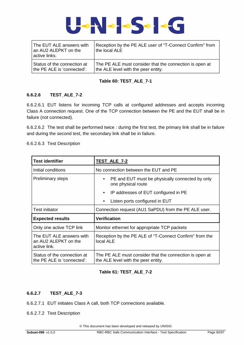
© This document has been developed and released by UNISIG
Subset-099 v1.0.0 RBC-RBC Safe Communication Interface - Test Specification Page 82/97
The EUT ALE answers with an AU2 ALEPKT on the active links.
Reception by the PE ALE user of “T-Connect Confirm” from the local ALE
Status of the connection at the PE ALE is ‘connected’.
The PE ALE must consider that the connection is open at the ALE level with the peer entity.
Table 60: TEST_ALE_7-1
6.6.2.6 TEST_ALE_7-2
6.6.2.6.1 EUT listens for incoming TCP calls at configured addresses and accepts incoming Class A connection request. One of the TCP connection between the PE and the EUT shall be in failure (not connected).
6.6.2.6.2 The test shall be performed twice : during the first test, the primary link shall be in failure and during the second test, the secondary link shall be in failure.
6.6.2.6.3 Test Description
Test identifier TEST_ALE_7-2
Initial conditions No connection between the EUT and PE
Preliminary steps • PE and EUT must be physically connected by only one physical route
• IP addresses of EUT configured in PE
• Listen ports configured in EUT
Test initiator Connection request (AU1 SaPDU) from the PE ALE user.
Expected results Verification
Only one active TCP link Monitor ethernet for appropriate TCP packets
The EUT ALE answers with an AU2 ALEPKT on the active link.
Reception by the PE ALE of “T-Connect Confirm” from the local ALE
Status of the connection at the PE ALE is ‘connected’.
The PE ALE must consider that the connection is open at the ALE level with the peer entity.
Table 61: TEST_ALE_7-2
6.6.2.7 TEST_ALE_7-3
6.6.2.7.1 EUT initiates Class A call, both TCP connections available.
6.6.2.7.2 Test Description

© This document has been developed and released by UNISIG
Subset-099 v1.0.0 RBC-RBC Safe Communication Interface - Test Specification Page 83/97
Test identifier TEST_ALE_7-3
Initial conditions No connection between the EUT and PE
Preliminary steps • PE and EUT must be physically connected by two physical routes
• IP addresses of PE configured in EUT
• Listen ports configured in PE
Test initiator Connection request (AU1 SaPDU) from the EUT ALE user.
Expected results Verification
Two TCP connections started by EUT
Monitor ethernet for appropriate TCP packets
The PE ALE should answer with an AU2 ALEPKT on the active link.
Reception by the EUT ALE user of “T-Connect Confirm” from the local ALE
The EUT ALE must consider that the connection is opening with the peer entity.
Status of the connection at the EUT ALE level.
TransportSequenceNumber has value “0”
Monitor ethernet for appropriate TCP packets
Table 62: TEST_ALE_7-3
6.6.2.8 TEST_ALE_7-4
6.6.2.8.1 EUT initiates Class A call, one TCP connection unavailable.
6.6.2.8.2 The test shall be performed twice : during the first test, the primary link shall be not connected and during the second test, the secondary link shall be not connected.
6.6.2.8.3 Test Description
Test identifier TEST_ALE_7-4
Initial conditions No connection between the EUT and PE
Preliminary steps • PE and EUT must be physically connected by only one physical route (second route disabled)
• IP addresses of PE configured in EUT
• Listen ports configured in PE
• One of PE ethernet ports is dis-connected.
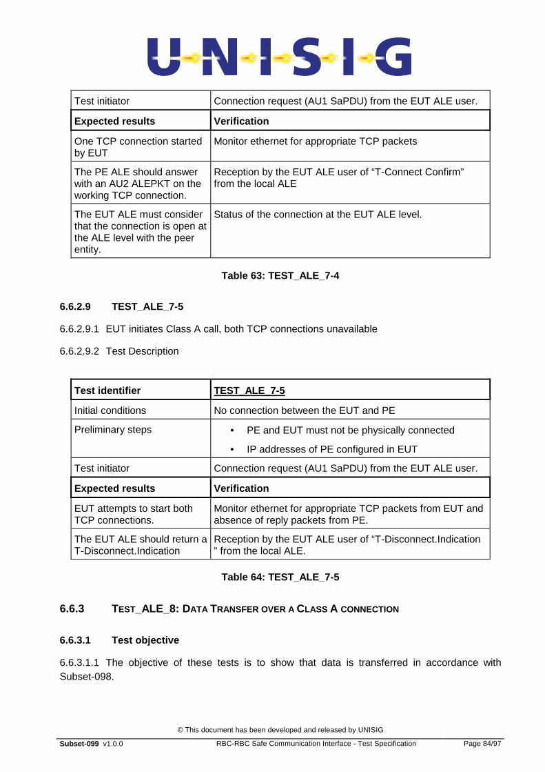
© This document has been developed and released by UNISIG
Subset-099 v1.0.0 RBC-RBC Safe Communication Interface - Test Specification Page 84/97
Test initiator Connection request (AU1 SaPDU) from the EUT ALE user.
Expected results Verification
One TCP connection started by EUT
Monitor ethernet for appropriate TCP packets
The PE ALE should answer with an AU2 ALEPKT on the working TCP connection.
Reception by the EUT ALE user of “T-Connect Confirm” from the local ALE
The EUT ALE must consider that the connection is open at the ALE level with the peer entity.
Status of the connection at the EUT ALE level.
Table 63: TEST_ALE_7-4
6.6.2.9 TEST_ALE_7-5
6.6.2.9.1 EUT initiates Class A call, both TCP connections unavailable
6.6.2.9.2 Test Description
Test identifier TEST_ALE_7-5
Initial conditions No connection between the EUT and PE
Preliminary steps • PE and EUT must not be physically connected
• IP addresses of PE configured in EUT
Test initiator Connection request (AU1 SaPDU) from the EUT ALE user.
Expected results Verification
EUT attempts to start both TCP connections.
Monitor ethernet for appropriate TCP packets from EUT and absence of reply packets from PE.
The EUT ALE should return a T-Disconnect.Indication
Reception by the EUT ALE user of “T-Disconnect.Indication ” from the local ALE.
Table 64: TEST_ALE_7-5
6.6.3 TEST_ALE_8: D ATA TRANSFER OVER A CLASS A CONNECTION
6.6.3.1 Test objective
6.6.3.1.1 The objective of these tests is to show that data is transferred in accordance with Subset-098.
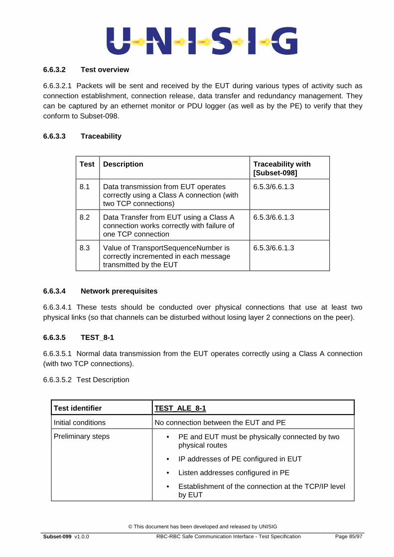
© This document has been developed and released by UNISIG
Subset-099 v1.0.0 RBC-RBC Safe Communication Interface - Test Specification Page 85/97
6.6.3.2 Test overview
6.6.3.2.1 Packets will be sent and received by the EUT during various types of activity such as connection establishment, connection release, data transfer and redundancy management. They can be captured by an ethernet monitor or PDU logger (as well as by the PE) to verify that they conform to Subset-098.
6.6.3.3 Traceability
Test Description Traceability with [Subset-098]
8.1 Data transmission from EUT operates correctly using a Class A connection (with two TCP connections)
6.5.3/6.6.1.3
8.2 Data Transfer from EUT using a Class A connection works correctly with failure of one TCP connection
6.5.3/6.6.1.3
8.3 Value of TransportSequenceNumber is correctly incremented in each message transmitted by the EUT
6.5.3/6.6.1.3
6.6.3.4 Network prerequisites
6.6.3.4.1 These tests should be conducted over physical connections that use at least two physical links (so that channels can be disturbed without losing layer 2 connections on the peer).
6.6.3.5 TEST_8-1
6.6.3.5.1 Normal data transmission from the EUT operates correctly using a Class A connection (with two TCP connections).
6.6.3.5.2 Test Description
Test identifier TEST_ALE_8-1
Initial conditions No connection between the EUT and PE
Preliminary steps • PE and EUT must be physically connected by two physical routes
• IP addresses of PE configured in EUT
• Listen addresses configured in PE
• Establishment of the connection at the TCP/IP level by EUT
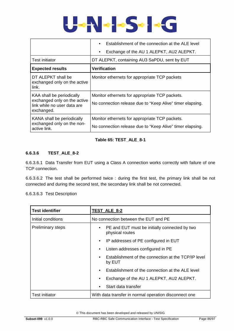
© This document has been developed and released by UNISIG
Subset-099 v1.0.0 RBC-RBC Safe Communication Interface - Test Specification Page 86/97
• Establishment of the connection at the ALE level
• Exchange of the AU 1 ALEPKT, AU2 ALEPKT.
Test initiator DT ALEPKT, containing AU3 SaPDU, sent by EUT
Expected results Verification
DT ALEPKT shall be exchanged only on the active link.
Monitor ethernets for appropriate TCP packets
KAA shall be periodically exchanged only on the active link while no user data are exchanged.
Monitor ethernets for appropriate TCP packets.
No connection release due to “Keep Alive” timer elapsing.
KANA shall be periodically exchanged only on the non-active link.
Monitor ethernets for appropriate TCP packets.
No connection release due to “Keep Alive” timer elapsing.
Table 65: TEST_ALE_8-1
6.6.3.6 TEST_ALE_8-2
6.6.3.6.1 Data Transfer from EUT using a Class A connection works correctly with failure of one TCP connection.
6.6.3.6.2 The test shall be performed twice : during the first test, the primary link shall be not connected and during the second test, the secondary link shall be not connected.
6.6.3.6.3 Test Description
Test identifier TEST_ALE_8-2
Initial conditions No connection between the EUT and PE
Preliminary steps • PE and EUT must be initially connected by two physical routes
• IP addresses of PE configured in EUT
• Listen addresses configured in PE
• Establishment of the connection at the TCP/IP level by EUT
• Establishment of the connection at the ALE level
• Exchange of the AU 1 ALEPKT, AU2 ALEPKT.
• Start data transfer
Test initiator With data transfer in normal operation disconnect one
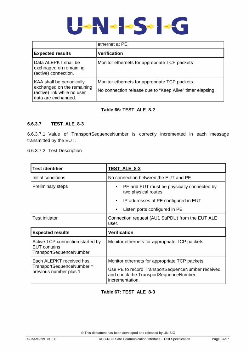
© This document has been developed and released by UNISIG
Subset-099 v1.0.0 RBC-RBC Safe Communication Interface - Test Specification Page 87/97
ethernet at PE.
Expected results Verification
Data ALEPKT shall be exchnaged on remaining (active) connection.
Monitor ethernets for appropriate TCP packets
KAA shall be periodically exchanged on the remaining (active) link while no user data are exchanged.
Monitor ethernets for appropriate TCP packets.
No connection release due to “Keep Alive” timer elapsing.
Table 66: TEST_ALE_8-2
6.6.3.7 TEST_ALE_8-3
6.6.3.7.1 Value of TransportSequenceNumber is correctly incremented in each message transmitted by the EUT.
6.6.3.7.2 Test Description
Test identifier TEST_ALE_8-3
Initial conditions No connection between the EUT and PE
Preliminary steps • PE and EUT must be physically connected by two physical routes
• IP addresses of PE configured in EUT
• Listen ports configured in PE
Test initiator Connection request (AU1 SaPDU) from the EUT ALE user.
Expected results Verification
Active TCP connection started by EUT contains TransportSequenceNumber
Monitor ethernets for appropriate TCP packets.
Each ALEPKT received has TransportSequenceNumber = previous number plus 1
Monitor ethernets for appropriate TCP packets
Use PE to record TransportSequenceNumber received and check the TransportSequenceNumber incrementation.
Table 67: TEST_ALE_8-3
© This document has been developed and released by UNISIG
Subset-099 v1.0.0 RBC-RBC Safe Communication Interface - Test Specification Page 88/97
6.6.4 TEST_ALE_9: R ELEASE OF A CLASS A CONNECTION
6.6.4.1 Test objective
6.6.4.1.1 The purpose of these tests is to demonstrate that the EUT ALE correctly handles all conditions that cause disconnection from the peer.
6.6.4.2 Test overview
6.6.4.2.1 Packets are sent and received by the EUT during various types of activity such as connection establishment, connection release, data transfer and redundancy management. They can be captured by an ethernet monitor or PDU logger (as well as by the PE) to verify that they conform to Subset-098.
6.6.4.3 Scenarios and Traceability
Test Description Traceability with [Subset-098]
9.1 Normal release of Class A connection (with two TCP connections) by initiator (EUT)
6.5.4/6.6.1.5/6.6.1.6
9.2 Normal release of Class A connection with one TCP connection already in failure, EUT being innitiator of the connection release.
6.5.4/6.6.1.5/6.6.1.6
9.3 Correct reaction by responder to normal release of Class A connection (with two TCP connections).
6.5.4/6.6.1.5/6.6.1.6
9.4 Normal release of Class A connection with one TCP connection already in failure,PE being innitiator of the connection release.
6.5.4/6.6.1.5/6.6.1.6
9.5 Release due to failure of both TCP connections (e.g. remote peer failure)
6.5.4/6.6.1.5/6.6.1.6
6.6.4.4 Network prerequisites
6.6.4.4.1 These tests should be conducted over physical connections that use at least two physical links (so that channels can be disturbed without losing layer 2 connections on the peer).
6.6.4.5 TEST_ALE_9-1
6.6.4.5.1 Ensure that Normal release of Class A connection (with two TCP connections) by initiator (EUT) works correctly.
6.6.4.5.2 Test Description

© This document has been developed and released by UNISIG
Subset-099 v1.0.0 RBC-RBC Safe Communication Interface - Test Specification Page 89/97
Test identifier TEST_ALE_9-1
Initial conditions No connection between RBC’s.
Preliminary steps • PE and EUT must be physically connected by two physical routes
• IP addresses of PE configured in EUT
• Listen addresses configured in PE
• Establishment of the connections at the TCP/IP level by EUT
• Establishment of the connection at the ALE level
• Establishment of safe connection
• Continuous data transfer.
Test initiator T-DISC.req (Disc SaPDU) received from EUT ALE user.
Expected results Verification
Release of the connection. All data delivered on both sides.
DI ALEPKT delivered to PE ALE on the active link.
ALE User connection closed Safe connection terminated.
TCP Connections released. Monitor ethernet for appropriate TCP packets (including TCP packet “FIN” + acks in both directions).
Table 68: TEST_ALE_9-1
6.6.4.6 TEST_ALE_9-2
6.6.4.6.1 Normal release of Class A connection with one TCP connection already in failure: EUT initiator of the disconnection.
6.6.4.6.2 The test shall be performed twice : during the first test, the primary link shall be not connected and during the second test, the secondary link shall be not connected.
6.6.4.6.3 Test Description
Test identifier TEST_ALE_9-2
Initial conditions No connection between RBC’s.
Preliminary steps • PE and EUT must be physically connected by one physical route
• IP addresses of PE configured in EUT
• Listen addresses configured in PE

© This document has been developed and released by UNISIG
Subset-099 v1.0.0 RBC-RBC Safe Communication Interface - Test Specification Page 90/97
• Establishment of the connections at the TCP/IP level by EUT
• Establishment of the connection at the ALE level
• Establishment of safe connection
• Continuous data transfer.
• Disconnection of one link at PE
Test initiator T-DISC.req (Disc SaPDU) received from EUT ALE user.
Expected results Verification
Release of the ALE connection.
All data delivered on both sides.
DI ALEPKT delivered to PE ALE.
ALE User connection closed Safe connection released.
Remaining TCP Connection released.
Monitor ethernet for appropriate TCP packets (including TCP packet “FIN” + acks in both directions).
Table 69: TEST_ALE_9-2
6.6.4.7 TEST_ALE_9-3
6.6.4.7.1 Correct reaction by responder (EUT) to normal release of Class A connection (with two TCP connections).
6.6.4.7.2 Test Description
Test identifier TEST_ALE_9-3
Initial conditions No connection between RBC’s.
Preliminary steps • PE and EUT must be physically connected by two physical routes
• IP addresses of PE configured in EUT
• Listen addresses configured in PE
• Establishment of the connections at the TCP/IP level by EUT
• Establishment of the connection at the ALE level
• Establishment of safe connection
• Continuous data transfer.
Test initiator DI ALEPKT received from PE ALE.

© This document has been developed and released by UNISIG
Subset-099 v1.0.0 RBC-RBC Safe Communication Interface - Test Specification Page 91/97
Expected results Verification
Release of the ALE connection.
All data delivered on both sides.
DI ALEPKT delivered on EUT ALE on the active link.
ALE User connection released
Safe connection terminated.
TCP Connections released. Monitor ethernet for appropriate TCP packets (including TCP packet “FIN” + acks in both directions).
Table 70: TEST_ALE_9-3
6.6.4.8 TEST_ALE_9-4
6.6.4.8.1 Normal release of Class A connection with one TCP connection already in failure : PE initiator of the disconnection.
6.6.4.8.2 The test shall be performed twice : during the first test, the primary link shall be not connected and during the second test, the secondary link shall be not connected.
6.6.4.8.3 Test Description
Test identifier TEST_ALE_9-4
Initial conditions No connection between RBC’s.
Preliminary steps • PE and EUT must be physically connected by one physical route
• IP addresses of PE configured in EUT
• Listen addresses configured in PE
• Establishment of the connections at the TCP/IP level by EUT
• Establishment of the connection at the ALE level
• Establishment of safe connection
• Continuous data transfer.
• Disconnection of one link at PE
Test initiator DI ALEPKT sent by the PE ALE.
Expected results Verification
Release of the ALE connection
All data delivered on both sides.
DI ALEPKT delivered on EUT on the remaining link.

© This document has been developed and released by UNISIG
Subset-099 v1.0.0 RBC-RBC Safe Communication Interface - Test Specification Page 92/97
ALE User connection closed Safe connection released.
Remaining TCP Connection released.
Monitor ethernet for appropriate TCP packets (including TCP packet “FIN” + acks in both directions).
Table 71: TEST_ALE_9-4
6.6.4.9 TEST_ALE_9-5
6.6.4.10 TEST_9-5
6.6.4.10.1 Release due to failure of both TCP connections (e.g. PE ALE failure).
6.6.4.10.2 Test Description
Test identifier TEST_ALE_9-5
Initial conditions No connection between RBC’s.
Preliminary steps • PE and EUT must be physically connected by two physical routes
• IP addresses of PE configured in EUT
• Listen addresses configured in PE
• Establishment of the connections at the TCP/IP level by EUT
• Establishment of the connection at the ALE level
• Establishment of safe connection
• Continuous data transfer.
Test initiator Power off PE or remove both links from PE
Expected results Verification
TCP Connections closed when error detected
EUT ALE abandons TCP connections (abort)
Monitor ethernet for appropriate TCP packets (including TCP packet “FIN” + acks in both directions).
T_Disconnect.Indication sent to local ALE user
Status of connection changes (to closed).
Table 72: TEST_ALE_9-5

© This document has been developed and released by UNISIG
Subset-099 v1.0.0 RBC-RBC Safe Communication Interface - Test Specification Page 93/97
6.6.5 TEST_ALE_10: R EDUNDANCY MANAGEMENT OF A CLASS A CONNECTION
6.6.5.1 Tests objective
6.6.5.1.1 These tests are designed to show that redundancy management operates as defined in Subset-098 for a Class A connection between conformant peers.
6.6.5.2 Test overview
6.6.5.2.1 Packets are sent and received by the EUT during various types of activity such as connection establishment, connection release, data transfer and redundancy management. They can be captured by an ethernet monitor or PDU logger (as well as by the PE) to verify that they conform to Subset-098.
6.6.5.3 Scenarios and Traceability
Test Description Traceability with Subset-098
10.1 Switch from primary and active link to secondary link initiated by EUT
6.5.3 / 6.6.1.4
10.2 Switch from secondary and active link to primary link initiated by EUT
6.5.3 / 6.6.1.4
10.3 Switch from primary and active link to secondary link initiated by PE.
6.5.3 / 6.6.1.4
10.4 Switch from secondary and active link to primary link initiated by PE.
6.5.3 / 6.6.1.4
6.6.5.4 Network prerequisites
6.6.5.4.1 These tests should be conducted over physical connections that use at least two physical links (so that channels can be disturbed without losing layer 2 connections on the peer).
6.6.5.5 TEST_ALE_10-1
6.6.5.5.1 Network failure on primary and active link. EUT initiates the switch.
6.6.5.5.2 The EUT under tests could be forced to initiate the switch if the “Keep Awake “ and TCP keep awake timers of the PE is several times bigger than the ones of the EUT.
6.6.5.5.3 Test Description
Test identifier TEST_ALE_10-1
Initial conditions No connection between RBC’s.

© This document has been developed and released by UNISIG
Subset-099 v1.0.0 RBC-RBC Safe Communication Interface - Test Specification Page 94/97
Preliminary steps • PE and EUT must be physically connected by two physical links
• IP addresses of PE configured in EUT
• Listen addresses configured in PE
• Establishment of the connections at the TCP/IP level by EUT
• Establishment of the connection at the ALE level
• Establishment of safe connection
• Continuous data transfer.
Test initiator The primary link is disconnected.
Expected results Verification
EUT recognises loss of TCP connection.
Timer expiry causes reset of TCP connection.
Bi-directional data flow proceeds on remaining (redunded) channel.
SwitchN2R ALEPKT sent on the secondary link by the EUT.
Expected data are correctly received by both peers.
The KAA ALEPKT are sent and received on the secdondary and active link.
Monitor ethernet for appropriate TCP packets.
Test initiator The primary link is reconnected.
Expected results Verification
Primary link restoration TCP connection re-established.
The KANA ALEPKT are sent and received on the primary and non-active link.
Monitor ethernet for appropriate TCP packets.
Table 73: TEST_ALE_10-1
6.6.5.6 TEST_ALE_10-2
6.6.5.6.1 Network failure on secondary and active link. EUT initiates the switch. As after the previous test the secondary link is the active one, the current test could be performed just after the TEST_ALE_10-1.
6.6.5.6.2 The EUT under tests could be forced to initiate the switch if the “Keep Awake “ and TCP keep awake timers of the PE is several times bigger than the ones of the EUT.
Test identifier TEST_ALE_10-2
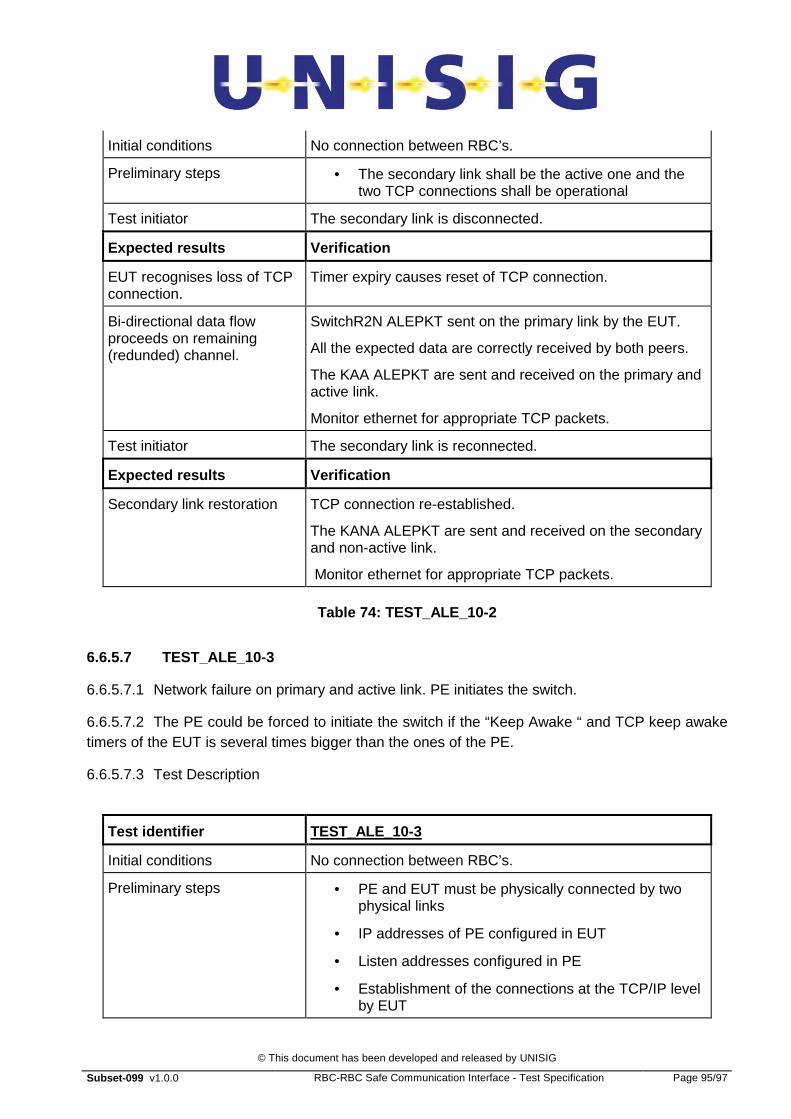
© This document has been developed and released by UNISIG
Subset-099 v1.0.0 RBC-RBC Safe Communication Interface - Test Specification Page 95/97
Initial conditions No connection between RBC’s.
Preliminary steps • The secondary link shall be the active one and the two TCP connections shall be operational
Test initiator The secondary link is disconnected.
Expected results Verification
EUT recognises loss of TCP connection.
Timer expiry causes reset of TCP connection.
Bi-directional data flow proceeds on remaining (redunded) channel.
SwitchR2N ALEPKT sent on the primary link by the EUT.
All the expected data are correctly received by both peers.
The KAA ALEPKT are sent and received on the primary and active link.
Monitor ethernet for appropriate TCP packets.
Test initiator The secondary link is reconnected.
Expected results Verification
Secondary link restoration TCP connection re-established.
The KANA ALEPKT are sent and received on the secondary and non-active link.
Monitor ethernet for appropriate TCP packets.
Table 74: TEST_ALE_10-2
6.6.5.7 TEST_ALE_10-3
6.6.5.7.1 Network failure on primary and active link. PE initiates the switch.
6.6.5.7.2 The PE could be forced to initiate the switch if the “Keep Awake “ and TCP keep awake timers of the EUT is several times bigger than the ones of the PE.
6.6.5.7.3 Test Description
Test identifier TEST_ALE_10-3
Initial conditions No connection between RBC’s.
Preliminary steps • PE and EUT must be physically connected by two physical links
• IP addresses of PE configured in EUT
• Listen addresses configured in PE
• Establishment of the connections at the TCP/IP level by EUT
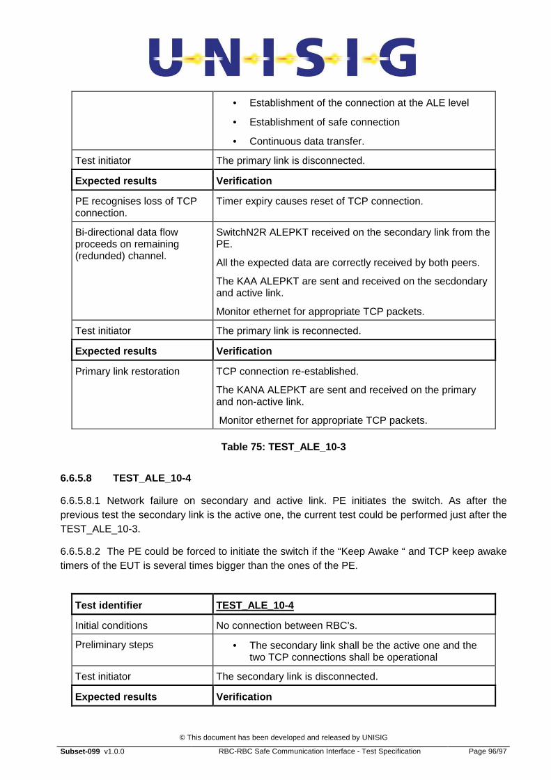
© This document has been developed and released by UNISIG
Subset-099 v1.0.0 RBC-RBC Safe Communication Interface - Test Specification Page 96/97
• Establishment of the connection at the ALE level
• Establishment of safe connection
• Continuous data transfer.
Test initiator The primary link is disconnected.
Expected results Verification
PE recognises loss of TCP connection.
Timer expiry causes reset of TCP connection.
Bi-directional data flow proceeds on remaining (redunded) channel.
SwitchN2R ALEPKT received on the secondary link from the PE.
All the expected data are correctly received by both peers.
The KAA ALEPKT are sent and received on the secdondary and active link.
Monitor ethernet for appropriate TCP packets.
Test initiator The primary link is reconnected.
Expected results Verification
Primary link restoration TCP connection re-established.
The KANA ALEPKT are sent and received on the primary and non-active link.
Monitor ethernet for appropriate TCP packets.
Table 75: TEST_ALE_10-3
6.6.5.8 TEST_ALE_10-4
6.6.5.8.1 Network failure on secondary and active link. PE initiates the switch. As after the previous test the secondary link is the active one, the current test could be performed just after the TEST_ALE_10-3.
6.6.5.8.2 The PE could be forced to initiate the switch if the “Keep Awake “ and TCP keep awake timers of the EUT is several times bigger than the ones of the PE.
Test identifier TEST_ALE_10-4
Initial conditions No connection between RBC’s.
Preliminary steps • The secondary link shall be the active one and the two TCP connections shall be operational
Test initiator The secondary link is disconnected.
Expected results Verification

© This document has been developed and released by UNISIG
Subset-099 v1.0.0 RBC-RBC Safe Communication Interface - Test Specification Page 97/97
EUT recognises loss of TCP connection.
Timer expiry causes reset of TCP connection.
Bi-directional data flow proceeds on remaining (redunded) channel.
SwitchR2N ALEPKT received on the primary link from the PE.
All the expected data are correctly received by both peers.
The KAA ALEPKT are sent and received on the primary and active link.
Monitor ethernet for appropriate TCP packets.
Test initiator The secondary link is reconnected.
Expected results Verification
Secondary link restoration TCP connection re-established.
The KANA ALEPKT are sent and received on the secondary and non-active link.
Monitor ethernet for appropriate TCP packets.
Table 76: TEST_ALE_10-2