rcl-ii locomotive remote control...
TRANSCRIPT
1
Smart Technology. Delivered.
RCL-II Locomotive Remote Control System
Operating Instructions
9M02-7564-A002

RCL-II Locomotive Remote Control
Operating Instructions
2 9M02-7564-A002
REVISION HISTORY
Revision Date Changes
1.0 Initial Release
2.0 05/2014 Updated Styles
Revised Content
3.0 09/2014 Added missing RCL-II features and OCU-III functionality.
3.1 12/2014 Updated images
Updated product names
New battery info
Added “Serviceability” appendix
3.2 06/2015 Added note to battery sections about yearly replacement
Minor content updates
Updated cleaning warning
3.3 07/2015 Added a warning note for the OCU/LCU antenna
connections
RCL-II Locomotive Remote Control
Operating Instructions
3 9M02-7564-A002
Table of Contents
Revision History ...................................................................................................................................................................................... 2
Table of Contents .................................................................................................................................................................................. 3
1 Important Notices ........................................................................................................................................................................ 4
2 Introduction to RCL-II ................................................................................................................................................................. 6
3 Reference Information ................................................................................................................................................................ 7
4 Safety Summary ............................................................................................................................................................................ 8
5 Safety Discussion ........................................................................................................................................................................ 12
6 System Description .................................................................................................................................................................... 16
7 Operating Instructions ............................................................................................................................................................. 46
8 System Summary – Technical Specifications .................................................................................................................... 71
Appendix I: OCU-III Serviceability ................................................................................................................................................. 74
Laird Wireless Automation & Control Solutions, Support Facilities ...................................................................................75

RCL-II Locomotive Remote Control
Operating Instructions
4 9M02-7564-A002
1 IMPORTANT NOTICES
1.1 American Association of Railroads [AAR] Terminology Conventions for Remote
Controlled Locomotives
The following AAR acronyms relate to items of unique and advanced Laird Locomotive Radio Remote
Controlled Equipment:
Laird Acronym ( ) Equivalent AAR Acronym [ ]
Locomotive Control Unit (LCU) Remote Control Receiver [RCR]
Operator Control Unit (OCU) Remote Control Transmitter [RCT]
Your new RCL-II system Locomotive Control Unit (LCU) is preconfigured to operate on a specific digital
address and between one and eight RF channels before leaving our factory. Operator Control Units (OCUs)
are programmed with a unique lifetime digital address before leaving our factory.
The LCU utilizes an Infrared TEACH/LEARN linking process to program the operating frequencies to the
OCUs.
Note that this manual describes all features that are currently available for RCL-II systems. This is because
RCL-II systems are engineered and manufactured by Laird to meet a specific railroad customer requirement –
in reality, no two railroad customer requirements will likely be identical.
While the majority of items and component parts described in this manual will be present in your installation,
there may be differences in: (1) the actual assembly/component location, (2) the control application, and (3)
the part number and quantity of these items.
This equipment was tested and found to comply with the limits for a Class A digital device, pursuant to Part
15 of the FCC Rules (unintentional radiators). These limits are designed to provide reasonable protection
against harmful interference when the equipment operates in a commercial environment. This equipment
generates, uses, and can radiate radio frequency energy and, if not installed and used in accordance with this
manual, may cause harmful interference to radio communications. Operation of this equipment in a
residential area is likely to cause harmful interference in which case the user will be required to correct the
interference at their own expense.
This equipment is firmware based, including encoder, decoder, transmitter and receiver. Any duplication of
operating firmware without written consent of Laird Controls Holdings Inc. is prohibited. All firmware,
product listings, assembly files, and this manual are protected by U.S. Copyright Laws.
1.2 Information to the User regarding FCC Compliance
Changes or modifications not expressly approved by the manufacturer could void the users’ authority to
operate the equipment.
This device complies with Part 15 of the FCC Rules. Operation is subject to the following two conditions; (1)
this device may not cause harmful interference, and (2) this device must accept any interference received,
including interference that may cause undesired operation.

RCL-II Locomotive Remote Control
Operating Instructions
5 9M02-7564-A002
1.3 Patent Notice
The RCL-II System described in this publication is protected by one or more of the following US Patents:
As part of our continuous improvement policy, Laird reserves the right to change specifications without
notice.
This manual is Proprietary and Confidential to Laird Controls Holdings Inc. The entire document including any or all of the information contained therein is not to be reproduced, disclosed, or used in whole or in part for any purpose without prior written authorization of Laird Controls Holdings Inc.

RCL-II Locomotive Remote Control
Operating Instructions
6 9M02-7564-A002
2 INTRODUCTION TO RCL-II
RCL-II (Remote Control for Locomotive) is a platform that is based on the best practices of the current
BELTPACK®
and ACCUSPEED™ products manufactured by Laird Controls Holdings Inc. The RCL-II platform
seamlessly supports and integrates a wide variety of control functions, some of which may include:
Locomotive Speed Control
Slow Speed Excitation Control
Electronic Position Detection (EPD)
Pullback Stopping Protection (PSP)
Electronic Handbrake Control and Monitoring
Monitoring Locomotive Feedback
Remote Monitoring through CattronConnect®
Interface
The RCL-II concept is based on a Locomotive Control Unit (LCU) that uses dual-processor architecture for:
Receiving and decoding messages from the Operator Control Units (OCUs)
Handling information from and to the various peripherals
Providing locomotive control
The LCU hardware (enclosure and inner Gold Box) is based on the existing ACCUSPEED™ configuration.
Consequently, all ACCUSPEED™ equipment currently in service can be upgraded to RCL-II configuration very
easily.
This is accomplished by substituting the RCL-II Decoder Board for the existing ACCUSPEED™ MP96GII
decoder board located inside the LCU Gold Box.
To summarize, the RCL-II Decoder Board is designed to:
Support the system hardware and safety requirements of the standard ACCUSPEED™ RCL product
Support the system hardware and safety requirements of any new application
Improve system reliability and performance
Improve system security and safety
Improve product serviceability and maintainability
Provide a platform for future expansion of the RCL product
Throughout this manual, specific references and versions of Laird ACCUSPEED®
OCUs are used in the terms
described in the following table.
ACCUSPEED®
OCU General Term that relates to operations and functions common across
OCU devices.
Legacy OCU References the initial OCU for ACCUSPEED®
.
OCU-III The new OCU solution with LEXAN™ housing and internal antenna
solution.

RCL-II Locomotive Remote Control
Operating Instructions
7 9M02-7564-A002
3 REFERENCE INFORMATION
3.1 List of Technical Abbreviations
The following abbreviations (acronyms) are frequently used in Laird radio remote control technology and
may be used in this manual:
ASO Automatic Safety Override NMEA National Marine Electronics Association
BCF Binary Configuration File Ni-MH Nickel Metal Hydride
CDMA Code Division Multiple Access OCU Operator Control Unit
DC Direct Current OEM Original Equipment Manufacturer
DIR Direction OPR Operate
EMI Electro-Magnetic Interference RCL Remote Controlled Locomotive
EPI Electro-Pneumatic Interface RCO Remote Control Operator
FRA Federal Railroad Administration RCT Remote Control Transmitter
GPS Global Positioning System RF Radio Frequency
IBO Independent Brake Override RFI Radio Frequency Interference
I/O Input/ Output RX Receive
IR Infrared STS™ Synchronized Timesharing System
LCD Liquid Crystal Display TA Throttle Advance (Generator Field)
LCU Locomotive Control Unit TX Transmit
LED Light Emitting Diode VAC Volts Alternating Current
LJB Locomotive Junction Box VDC Volts Direct Current
NEMA National Electrical Manufacturers
Association

RCL-II Locomotive Remote Control
Operating Instructions
8 9M02-7564-A002
4 SAFETY SUMMARY
WARNING and CAUTION statements have been strategically placed throughout all text prior to operating
procedures, practices or conditions considered essential to the protection of personnel (WARNING), or
equipment and property (CAUTION). A WARNING and CAUTION applies each time the related step is
repeated. Before starting any task, the WARNINGS or CAUTIONS included in the text for the task shall be
reviewed and understood. All WARNINGS and CAUTIONS appearing in this manual are included below.
4.1 Warnings
WARNING:
ALL REMOTE OPERATED LOCOMOTIVES SHALL HAVE AUDIO OR VISUAL ALARM/WARNING INDICATIONS WHICH MEET APPROPRIATE GOVERNMENTAL REQUIREMENTS. FAILURE TO IMPLEMENT THIS WARNING MAY RESULT IN SERIOUS INJURY OR DEATH TO PERSONNEL AND DAMAGE TO EQUIPMENT.
WARNING:
TO SATISFY FCC RF EXPOSURE REQUIREMENTS FOR PORTABLE TRANSMITTING DEVICES, A MINIMUM SEPARATION DISTANCE OF 2.5 CM (APPROX. 1 INCH) SHOULD BE MAINTAINED BETWEEN THE ANTENNA OF THE OCU AND PERSONS DURING DEVICE OPERATION. TO INSURE COMPLIANCE, OPERATION AT CLOSER THAN THIS DISTANCE IS NOT RECOMMENDED. FAILURE TO COMPLY WITH THIS WARNING MAY RESULT IN SERIOUS INJURY OR DEATH TO PERSONNEL AND DAMAGE TO EQUIPMENT.
WARNING:
THE LOCOMOTIVE 3-WAY TRANSFER VALVE MUST BE SECURED WITH A LOCKING MECHANISM IN BOTH THE REMOTE AND MANUAL POSITIONS. FAILURE TO IMPLEMENT THIS WARNING MAY RESULT IN THE LOSS OF BRAKES, WHICH IN TURN MAY RESULT IN SERIOUS INJURY OR DEATH TO PERSONNEL AND/OR DAMAGE TO EQUIPMENT.
WARNING:
TO SATISFY FCC RF EXPOSURE REQUIREMENTS FOR MOBILE TRANSMITTING DEVICES, A MINIMUM SEPARATION DISTANCE OF 36 CM (APPROX. 14 INCHES) SHOULD BE MAINTAINED BETWEEN THE ANTENNA OF THE LCU AND PERSONS DURING DEVICE OPERATION. TO INSURE COMPLIANCE, OPERATION AT CLOSER THAN THIS DISTANCE IS NOT RECOMMENDED. FAILURE TO COMPLY WITH THIS WARNING MAY RESULT IN SERIOUS INJURY OR DEATH TO PERSONNEL AND DAMAGE TO EQUIPMENT.
RCL-II Locomotive Remote Control
Operating Instructions
9 9M02-7564-A002
WARNING:
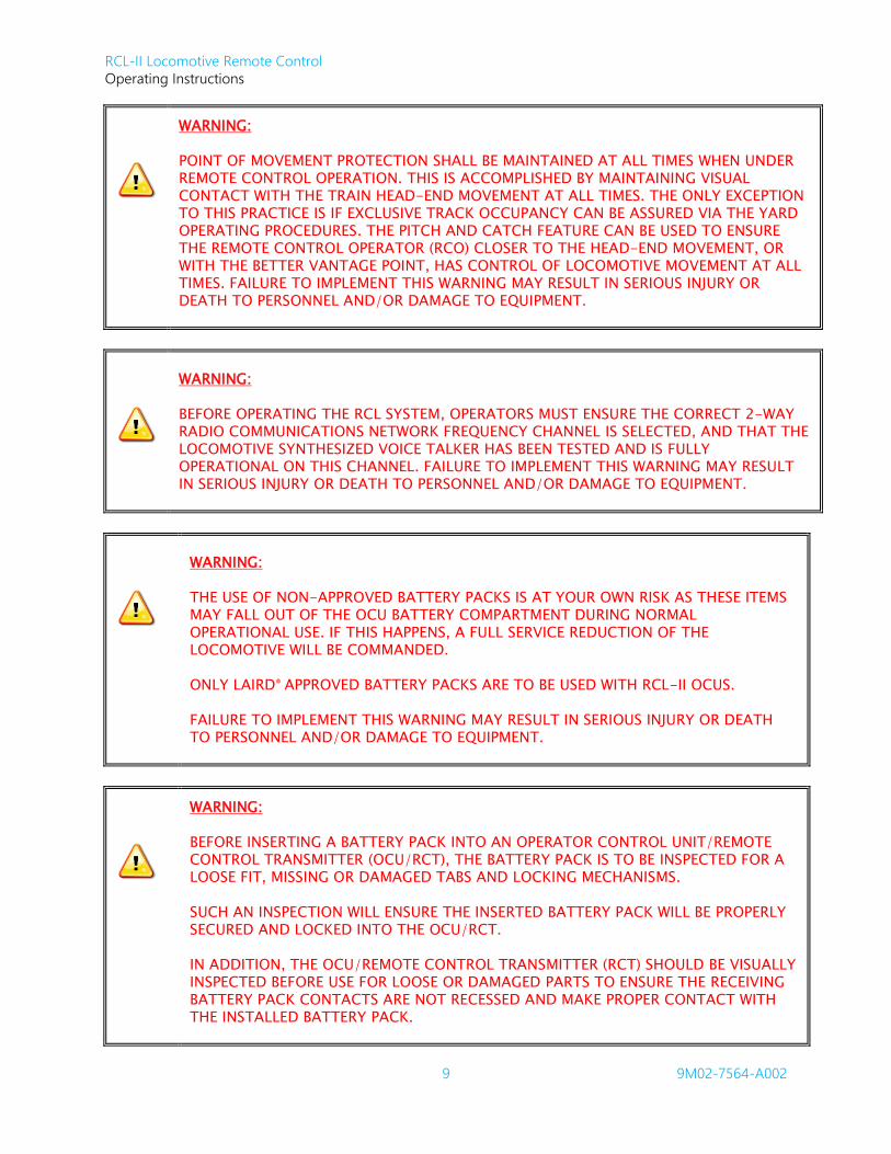
POINT OF MOVEMENT PROTECTION SHALL BE MAINTAINED AT ALL TIMES WHEN UNDER REMOTE CONTROL OPERATION. THIS IS ACCOMPLISHED BY MAINTAINING VISUAL CONTACT WITH THE TRAIN HEAD-END MOVEMENT AT ALL TIMES. THE ONLY EXCEPTION TO THIS PRACTICE IS IF EXCLUSIVE TRACK OCCUPANCY CAN BE ASSURED VIA THE YARD OPERATING PROCEDURES. THE PITCH AND CATCH FEATURE CAN BE USED TO ENSURE THE REMOTE CONTROL OPERATOR (RCO) CLOSER TO THE HEAD-END MOVEMENT, OR WITH THE BETTER VANTAGE POINT, HAS CONTROL OF LOCOMOTIVE MOVEMENT AT ALL TIMES. FAILURE TO IMPLEMENT THIS WARNING MAY RESULT IN SERIOUS INJURY OR DEATH TO PERSONNEL AND/OR DAMAGE TO EQUIPMENT.
WARNING:
BEFORE OPERATING THE RCL SYSTEM, OPERATORS MUST ENSURE THE CORRECT 2-WAY RADIO COMMUNICATIONS NETWORK FREQUENCY CHANNEL IS SELECTED, AND THAT THE LOCOMOTIVE SYNTHESIZED VOICE TALKER HAS BEEN TESTED AND IS FULLY OPERATIONAL ON THIS CHANNEL. FAILURE TO IMPLEMENT THIS WARNING MAY RESULT IN SERIOUS INJURY OR DEATH TO PERSONNEL AND/OR DAMAGE TO EQUIPMENT.
WARNING:
THE USE OF NON-APPROVED BATTERY PACKS IS AT YOUR OWN RISK AS THESE ITEMS MAY FALL OUT OF THE OCU BATTERY COMPARTMENT DURING NORMAL OPERATIONAL USE. IF THIS HAPPENS, A FULL SERVICE REDUCTION OF THE LOCOMOTIVE WILL BE COMMANDED.
ONLY LAIRD® APPROVED BATTERY PACKS ARE TO BE USED WITH RCL-II OCUS.
FAILURE TO IMPLEMENT THIS WARNING MAY RESULT IN SERIOUS INJURY OR DEATH TO PERSONNEL AND/OR DAMAGE TO EQUIPMENT.
WARNING:
BEFORE INSERTING A BATTERY PACK INTO AN OPERATOR CONTROL UNIT/REMOTE CONTROL TRANSMITTER (OCU/RCT), THE BATTERY PACK IS TO BE INSPECTED FOR A LOOSE FIT, MISSING OR DAMAGED TABS AND LOCKING MECHANISMS.
SUCH AN INSPECTION WILL ENSURE THE INSERTED BATTERY PACK WILL BE PROPERLY SECURED AND LOCKED INTO THE OCU/RCT.
IN ADDITION, THE OCU/REMOTE CONTROL TRANSMITTER (RCT) SHOULD BE VISUALLY INSPECTED BEFORE USE FOR LOOSE OR DAMAGED PARTS TO ENSURE THE RECEIVING BATTERY PACK CONTACTS ARE NOT RECESSED AND MAKE PROPER CONTACT WITH THE INSTALLED BATTERY PACK.

RCL-II Locomotive Remote Control
Operating Instructions
10 9M02-7564-A002
IF ANY OF THESE DEFECTS (OR ANY OTHER DEFECTS) ARE PRESENT, THE BATTERY PACK OR OCU/RCT SHALL NOT BE USED. SUCH DEFECTIVE ITEMS MUST BE TAGGED ACCORDING TO THE RULES SET FORTH BY THE CUSTOMER RAILROAD TO PREVENT THESE ITEMS BEING USED BY ANY OTHER PARTY.
IN RESPECT OF THE AFOREMENTIONED, IT SHOULD BE FULLY UNDERSTOOD THAT LAIRD® WILL NOT BE HELD LIABLE FOR PERSONAL INJURY, DEATH, EQUIPMENT OR PROPERTY DAMAGE ARISING FROM THE USE OF DEFECTIVE BATTERY PACKS OR OPERATOR CONTROL UNITS/REMOTE CONTROL TRANSMITTERS.
FAILURE TO IMPLEMENT THIS WARNING MAY RESULT IN SERIOUS INJURY OR DEATH TO PERSONNEL AND/OR DAMAGE TO EQUIPMENT.
WARNING:
THE USE OF UNAPPROVED COMPONENTS OR ACCESSORIES IN THE SYSTEMS SOLD BY LAIRD CONTROLS HOLDINGS INC AND ITS SUBSIDIARIES IS STRICTLY PROHIBITED. UNAPPROVED COMPONENTS ARE DEFINED AS ANY COMPONENT NOT INSPECTED AND SOLD BY LAIRD. THIS ALSO INCLUDES ANY COMPONENT MODIFIED FROM ITS INTENDED USE AND/OR ANY COMPONENT EXHIBITING OBSERVABLE DAMAGE OR DEFECT. USE OF NON-CONFORMING PARTS, ASSEMBLIES AND ACCESSORIES MAY LEAD TO INJURY OR DEATH.
WARNING:
THE REMOTE CONTROL SYSTEM YOU HAVE PURCHASED IS DESIGNED TO STOP IN A SAFE MODE UNDER A VARIETY OF CONDITIONS. SOME EXAMPLES OF THESE CONDITIONS ARE: EXCESSIVE RADIO SIGNAL INTERFERENCE, LOSS OF BATTERY AND OR ELECTRICAL POWER, FAILURE OF CERTAIN COMPONENTS AND OPERATION BEYOND SIGNAL RANGE AND OTHERS. ALTHOUGH LAIRD CONTROLS HOLDINGS INC AND ITS SUBSIDIARIES DO NOT SPECIFY THE POSITION OF THE OPERATOR WHEN CONTROLLING THE EQUIPMENT WE ARE AWARE THAT SOME USERS ARE INSTRUCTED AND TRAINED BY THEIR EMPLOYER TO RIDE THE EQUIPMENT IN A SAFE MANNER. IT IS IMPERATIVE THAT YOU ARE PREPARED FOR AN UNPLANNED STOP OF THE EQUIPMENT AT ANY TIME AND DO NOT PLACE YOURSELF OR OTHERS IN A POSITION WHERE THIS SITUATION MAY CAUSE YOU TO FALL FROM THE EQUIPMENT. FAILURE TO USE CAUTION MAY LEAD TO INJURY OR DEATH.

RCL-II Locomotive Remote Control
Operating Instructions
11 9M02-7564-A002
4.2 Cautions
CAUTION:
Laird® battery conditioners are designed for use with Laird® battery packs only.
Removed or disconnect battery packs from battery conditioners within 48-hours of achieving the fully charged state.
Failure to comply with these cautions may result in equipment and/or battery damage and will void our warranty.
CAUTION:
The OCU-III uses a polycarbonate housing that is suitable for rugged environments and radio frequency transmission. This plastic is reactive to a number of chemicals and therefore may only be cleaned using a mild soap solution with water, methyl or isopropyl alcohol, heptane, or hexane. No other solutions are approved for use by Laird. Laird is not responsible for damage to devices caused by the use of any other solutions that will void the warranty.
This exterior material WILL BE DAMAGED if exposed to chemicals/ solutions and adhesives commonly found in cleaning products. The chemicals that may cause damage include, but are not limited to: partially hydrogenated hydrocarbons, ketones (such as MEK), strong acids, alkalines (such as sodium hydroxide), or other similar products. Using unauthorized solutions to clean the housing will result in damage and void the warranty.
CAUTION:
The D-Rings, on the outside of the housing, are designed to allow customers to replace them if needed. For replacement of the D-Rings, Loctite 425™ may be used per the instructions provided with Kit Numbers: K2002, K2003, and K2004. No other adhesives are approved for use by Laird. Laird is not responsible for damage to devices caused by the use of any other adhesives.
RCL-II Locomotive Remote Control
Operating Instructions
12 9M02-7564-A002
5 SAFETY DISCUSSION
The documentation of these safety features and instructions are a direct result of the safety analysis
conducted during the RCL-II development lifecycle. If any changes are made to this section, they must be
reviewed by Safety Engineering to ensure consistency with the Safety Analysis documentation.
RCL-II OCUs employ a simple, single lever for locomotive speed selection. This lever sends commands to the
on-board LCU, which in turn provides the means to control the locomotive throttle and brakes as necessary
to maintain that selected speed. Separate brake override switches are provided for rare cases where the job
requires that the operator must override the LCU.
Visual displays and audible tones confirm that the action requested by the operator has been received and
correctly interpreted at the locomotive. RCL-II provides this advanced capability with an effective use of two
way digital technology, combined with simple two color LED indicators, audible tones, and a text status
display for times when the operator requests more detailed information.
Careful thought has gone into the overall design so that the LCU provides needed timely data in a way that
will not cause the operator to tune out important information, as is often the case with synthesized voice
messaging systems used for status messages.
Ergonomic design considerations allow a heads up operating scenario by providing audible warnings to alert
the operator to important conditions that are safety related, i.e., tilt (Man Down), and impending Full Service
Brake Application due to any loss of the communications link.
The FRA safety advisory requires that the locomotive be brought to a STOP if there is communications loss
greater than five seconds. The RCL-II goes well beyond this minimum requirement to solve a serious
potential operational problem of remote control locomotives that occurs upon loss of communications.
If the communication loss continues to the full term of five seconds, the operators are presented a timely
audible warning that an unsolicited Full Service Brake Application is about to occur. This allows operators to
be prepared if they are riding the side of a car. After the full term of the FRA mandated communication loss
is reached and a stop is initiated, a special operator command sequence is required to recover the system.
5.1 Proprietary OCU Assignment Process
The RCL-II System uses a proprietary means whereby an OCU is assigned to an LCU. This process was
created to ensure that an assigned OCU can communicate with only one LCU and conversely that the LCU
can communicate with only one OCU A and only one OCU B. For as long as an OCU is assigned to the LCU,
it indicates the assigned RCL Running Number on the OCU Display. Consequently, whenever an OCU is
switched on, it is essential that the RCO verifies that the OCU in hand is assigned to the appropriate LCU
(RCL).
Note: If the LCU is subsequently reassigned, the displayed RCL Running Number on the OCU will be
obsolete and no longer indicative of a valid LCU assignment. However, for safety reasons,
whenever an OCU displays an RCL Running Number, that OCU shall always be treated as a live
(controlling) OCU that has the capability of affecting an RCL.
Upon completion of a shift operating an OCU/RCL system, these devices can remain assigned or linked to
each other even after the OCU is switched off. When the OCU is switched on again, it can be ready to control
the RCL. For this reason, it is important for the client railroad to manage unattended OCU devices with care.
An OCU that remains assigned to an RCL must be treated as a potentially controlling OCU. Therefore it
should be secured (locked away) to prevent any unintentional manipulation of the OCU. On the other hand,
the OCU can be actively unlinked from the RCL, rendering the OCU inoperative. Methods for actively
unlinking the OCUs will be described in subsequent sections of this manual.

RCL-II Locomotive Remote Control
Operating Instructions
13 9M02-7564-A002
5.2 OCU Low Battery Warning
When the OCU activates the Low Battery Warning, it is recommended that the RCO make plans to replace
the OCU battery as soon as convenient. Once the battery power drops too low the OCU ceases transmitting,
resulting in a Full Service Train Brake Application.
Note: Before changing a Battery pack, the RCO must bring the RCL safely to a halt and switch off the
OCU. These actions will prevent any unexpected train movement had the battery power been
allowed to deplete until OCU transmissions ceased.
5.3 OCU Alerter Function
The OCU Alerter function provides the RCO with an audible indication that a Fault Stop has just been
initiated, and therefore train action is imminent.
Note: Whenever the RCO is riding on moving equipment and the OCU generates an Audible Warning, it
is essential that the RCO take heed of this notification. There is a possibility that a System induced
Fault Stop has been generated and therefore train action is imminent.
5.4 RCO Evasive Action
RCL-II is a Speed Control System and is therefore responsible for activating and maintaining the required
Throttle or Independent Brakes in order to achieve and maintain the commanded Speed Set Point. However,
it is essential that the RCO remain aware that the RCL movement corresponds to the desired movement. If
the RCO determines that the RCL movement is not as required or expected, it is the responsibility of the RCO
to take evasive action. Potential evasive actions available are:
OCU Speed Selector to STOP
Switch off OCU
OCU EMERG (Independent Brake Override)
Tilt OCU
E-Stop
5.5 Vigilance Safety Lift Sequence
The Vigilance Safety Lift Sequence acts to protect against inadvertent and unexpected movement of the RCL
with a simple bump of the OCU Speed Selector. This feature is in compliance with FRA Safety Advisory 2001-
01, Section A-5. It is recommended that the RCO verify that the OCU Direction Switch and corresponding
Talkback LEDs are properly set immediately before executing a Vigilance Safety Lift Sequence.
Note: The RCO must first activate either VIGILANCE switch then select the desired speed within 7-
seconds. If the RCO fails to select a speed within the 7-second window, he or she will be required
to activate either VIGILANCE switch before making another selection.
Upon successful execution of this Vigilance Safety Lift Sequence, the System responds by:
Releasing the Independent Brakes
Start applying tractive effort
Activate the Impending Movement Bell feature
The System automatically activates the RCL Bell as a means of warning persons in the vicinity that the RCL is
about to move.

RCL-II Locomotive Remote Control
Operating Instructions
14 9M02-7564-A002
5.6 Start of Shift Test
Before proceeding to operate an RCL-II system it is strongly recommended that at the start of every shift, or
after a new OCU/LCU assignment, the following items are tested:
OCU Vigilance
TILT Test of Primary and then Secondary OCU
Initial Movement Test
Visual inspection of RCL Brake Cylinder pistons (ensure pistons are extended)
5.7 OCU Talkback – LED Status for Legacy OCU
Function LEDs are located on the top panel of the OCU which allow the operator to monitor critical status
information being sent from the locomotive. The LEDs confirm the position of the select levers and toggle
switches and are bicolor in design.
When the operator commands a function from the OCU, the corresponding LED turns RED. When the LCU
has received and implemented the command, it transmits a confirmation (feedback) signal to the OCU
turning the LED green. This provides a positive conformation to the operator that the command was
received and acted upon by the LCU.
It is the responsibility of the RCO to ensure that the OCU command status is in correspondence with current
desired commands. That is:
Upon making an OCU command change, the RCO shall confirm that the corresponding LED reflects
the desired command status (Red).
The RCO shall confirm that the LCU has recognized the desired command status as indicated by the
corresponding Green LED status.
This indicates that the System has properly recognized and acted upon the desired command change. If the
RCO detects that the RCL-II System is not processing the OCU commands as required, the RCO shall take
evasive action.
5.8 OCU Talkback – LED Status for OCU-III
Note: OCU-III utilizes LED coloring compliant with the FRA Human Factors Guidelines for RCL Systems
(DOT/FRA/ORD-07/19). The FRA recommendation is that green is used for permissive settings,
while red is used to indicate safety-critical settings, warnings and the cultural convention of stop.
Because of this, all commanded settings will appear as amber until confirmed as being active
settings by RCL-II. Once confirmed, Emergency and Stop will show as red. All other settings will
appear as green.
Function LEDs are located on the top of the OCU which allow the operator to monitor critical status
information being sent from the locomotive. The LEDs are used to confirm the position of the select levers
and toggle switches and are tri-color in design.
When the operator commands a function from the OCU, the corresponding LED will turn AMBER. When the
LCU has received and implemented the command, it will transmit a confirmation (feedback) signal to the
OCU, turning the LED GREEN or RED, depending on the location of the LED. This provides a positive
conformation to the operator that the command has been received and acted upon by the LCU.

RCL-II Locomotive Remote Control
Operating Instructions
15 9M02-7564-A002
It is the responsibility of the RCO to ensure that the OCU command status is in correspondence with current
desired commands. That is:
Firstly, upon making an OCU command change, the RCO shall confirm that the corresponding LED
reflects the desired command status.
Secondly, the RCO shall confirm that the LCU has recognized the desired command status as indicated
by the corresponding LED status.
This indicates that the System has properly recognized and acted upon the desired command change. If the
RCO detects that the RCL-II System is not processing the OCU commands as required, the RCO shall take
evasive action.

RCL-II Locomotive Remote Control
Operating Instructions
16 9M02-7564-A002
6 SYSTEM DESCRIPTION
6.1 Introduction
Ideal for heavy-duty operation in harsh working environments, RCL-II Systems have been specifically
designed, with Railroad Operations input, for advanced locomotive, rail-yard, and railroading remote control
applications. In addition, properly configured RCL-II Systems meet and exceed the FRA Safety Advisory 2001-
01 for Remote Control Operation on FRA regulated railroads.
RCL-II utilizes a Locomotive Computer Unit (LCU) an optional companion Electro-Pneumatic Interface (EPI) in
conjunction with two specialized Operator Control Units (OCUs) to accurately control train speed in a wide
variety of regimens, by complete computerized control of throttle and brake systems.
When applicable, all control wiring between the Locomotive and your RCL-II system originates from a
Locomotive mounted Junction Box (LJB). Using interconnecting cables with quick connect/disconnect plugs
allows individual on-board enclosures to be quickly swapped out if required.
As an optional feature, the RCL-II system can be configured with a Remote Display. This small enclosure
contains everything that is required for normal RCO interaction with the system. The operator can Assign
OCU(s), access system menus or reset faults from this display. Typically, if this option is included it is intended
to ease installation of the complete system. In many cases, the majority of the system components are
mounted in locations that are “out of the way” from normal operations. The Remote Display is then installed
in the cab to accommodate normal operations.
6.2 Basic Operation
6.2.1 System Overview
Figure 1 shows a simplified block diagram of a typical RCL-II system.
The target LCU is controlled by the previously linked OCU, which sends signals to the LCU using a radio
frequency (RF) link. The signal is picked up by the antenna and passed on to the receiver. Provided the RF
frequency of the OCU exactly matches that of the target LCU receiver and passes all data tests, the signal
passes on to the LCU decoder for processing.
The LCU computer compares the address code of the transmitted RF signal from the OCU with its own
address code. If the signal address code does not match the LCU computer address code, it is ignored. If the
address code is correct, the LCU computer processes the message and energizes or de-energizes the
appropriate control, auxiliary, and pneumatic function devices located within the control system.

RCL-II Locomotive Remote Control
Operating Instructions
17 9M02-7564-A002
Figure 1: Typical RCL-II System - simplified block diagram
6.2.2 Automatic Safety Override (ASO)
The Automatic Safety Override (ASO) function continually monitors all critical function relay outputs from the
RCL-II decoder. The ASO circuit disables the OPR if a critical function output relay is active when no
corresponding command is being received from the OCU. In this event, no action is required by the operator
to stop the locomotive. The ASO safety circuitry stops motion automatically without any operator command
when a critical function output relay fault is detected.
6.2.3 Multiple Watchdog Circuits
The RCL-II decoder incorporates multiple hardware and software watchdog circuits designed to assert a safe
state of the locomotive when conditions are not valid to allow continued operation. These safety circuits
ultimately disconnect the critical function output relays (OPR #1 and OPR #2) in order to remove tractive
effort and apply brakes.
Hardware watchdogs are electronic component timers that turn off if they are not constantly reactivated and
reset by valid, fully decoded messages.
Software watchdogs are similar to the hardware watchdogs, except they are timed by the control and data
processors. They perform the same shut-down operation when valid messages stop being decoded.
Software and hardware watchdogs work together in pairs, one backing up the other.
Both of the RCL-II processors have software that is written with embedded watchdog timers to ensure proper
code sequences occur.
6.2.4 Dual Processors
The RCL-II decoder board employs two processors that interface with various I/O devices to maintain the
safety and integrity of system functions. The two processors have some tasks that are unique to one or the
other processor, but the processors are in constant communication to compare data points for critical
functions. If there is a disagreement between the processors readings, the safer action is taken. If this
disagreement persists then the system generates a penalty that will remove tractive effort and apply brakes.

RCL-II Locomotive Remote Control
Operating Instructions
18 9M02-7564-A002
6.2.5 System Initialization
When the LCU power is turned on, a self-test cycle of RCL system initialization and test routines occurs.
Referring to Figure 2, after completing the self-test cycle, the System Status Display shows the default screen.
This screen is displayed during normal operating conditions with or without a controller properly addressing
the system. Note that Faults or other information will override this display at times – refer to Figure 3 for an
example of a typical Message Bulletin Display.
Typically, the System Status Display default screen can be interpreted as follows:
Figure 2: Example System Status Display default screen
Line 1
Line 2
Line 1
Line 2
Figure 3: Example - alternative Message Bulletin Display
System Status Display default screen interpretations: Referring to Figure 2, typically the System Status Display
default screen can be interpreted as follows:
Line 1:
1. Moving Square: Represents execution process and responsiveness by moving from left to right and
from right to left
2. Communication Status:
a. OFF: Offline
b. ACT: Activity
c. OPRs have not been tested, or only one OCU is responding to Offline polls when two OCUs
are assigned.
3. Direct/Repeater Mode: D- Direct, R- Repeater
4. Frequency
5. Time Slot
6. R followed by active repeater zone number
RCL-II Locomotive Remote Control
Operating Instructions
19 9M02-7564-A002
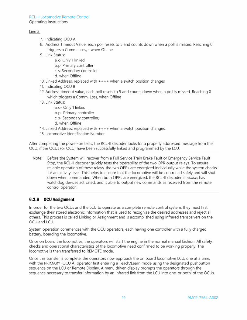
Line 2:
7. Indicating OCU A
8. Address Timeout Value, each poll resets to 5 and counts down when a poll is missed. Reaching 0
triggers a Comm. Loss, - when Offline
9. Link Status:
a. o: Only 1 linked
b. p: Primary controller
c. s: Secondary controller
d. when Offline
10. Linked Address, replaced with ++++ when a switch position changes
11. Indicating OCU B
12. Address timeout value, each poll resets to 5 and counts down when a poll is missed. Reaching 0
which triggers a Comm. Loss, when Offline
13. Link Status:
a. o- Only 1 linked
b. p- Primary controller
c. s- Secondary controller,
d. when Offline
14. Linked Address, replaced with ++++ when a switch position changes.
15. Locomotive Identification Number
After completing the power-on tests, the RCL-II decoder looks for a properly addressed message from the
OCU, if the OCUs (or OCU) have been successfully linked and programmed by the LCU.
Note: Before the System will recover from a Full Service Train Brake Fault or Emergency Service Fault
Stop, the RCL-II decoder quickly tests the operability of the two OPR output relays. To ensure
reliable operation of these relays, the two OPRs are energized individually while the system checks
for an activity level. This helps to ensure that the locomotive will be controlled safely and will shut
down when commanded. When both OPRs are energized, the RCL-II decoder is online, has
watchdog devices activated, and is able to output new commands as received from the remote
control operator.
6.2.6 OCU Assignment
In order for the two OCUs and the LCU to operate as a complete remote control system, they must first
exchange their stored electronic information that is used to recognize the desired addresses and reject all
others. This process is called Linking or Assignment and is accomplished using Infrared transceivers on the
OCU and LCU.
System operation commences with the OCU operators, each having one controller with a fully charged
battery, boarding the locomotive.
Once on board the locomotive, the operators will start the engine in the normal manual fashion. All safety
checks and operational characteristics of the locomotive need confirmed to be working properly. The
locomotive is then transferred to REMOTE mode.
Once this transfer is complete, the operators now approach the on board locomotive LCU, one at a time,
with the PRIMARY (OCU A) operator first entering a Teach/Learn mode using the designated pushbutton
sequence on the LCU or Remote Display. A menu driven display prompts the operators through the
sequence necessary to transfer information by an infrared link from the LCU into one, or both, of the OCUs.

RCL-II Locomotive Remote Control
Operating Instructions
20 9M02-7564-A002
A typical scenario would be the first operator approaching the LCU or Remote Display, starting the process
on his/her OCU, and following the instructions on the display in sequence. At the proper time in the
sequence, the OCU automatically begins infrared communications with the LCU. The OCU indicates progress
on the display while the data exchange is in progress, and the LCU and OCU displays will show when the
programming cycle is complete for that OCU. The second OCU operator will now approach the LCU or
Remote Display, starting the process on the SECONDARY OCU, again following the instructions on the LCU
display in sequence.
The data transferred via the infrared link consists of the locomotive ID number, the individual address from
each handheld OCU into the on board LCU, and the transfer of the LCU address and frequency to the
handheld OCU(s). When this Teach/Learn process is completed, both OCUs will have all necessary
information programmed into them to safely and accurately operate as a system.
Part of the infrared Teach/Learn linking process is to identify the initial PRIMARY OCU and the SECONDARY
OCU. By identifying and programming one of the OCUs as SECONDARY, limits are placed on the scope of
operation that it is capable of performing. In other words, the programmed data message for the
SECONDARY OCU is unique from the PRIMARY OCU, being shorter in word length, and without the
command authority of the PRIMARY OCU. The role of Primary and Secondary can be switched between
operators through the Pitch and Catch process that will be discussed later in this manual.
In some cases the SECONDARY OCU may not be utilized, in which case this step is skipped resulting in
PRIMARY only operation.
If required by the operating rules at your rail yard, OCUs may be configured to unlink from the LCU:
1. When LCU power is powered off or set to Manual Mode for a predetermined time period.
2. By starting the Infrared Assignment process and pressing the NO/FUNCTION pushbutton on the
LCU when asked to proceed.
3. By initiating the Infrared Assignment process on the OCU and allowing the procedure to time out.
6.3 Operator Control Unit (A010* Model) – Functional Description
The lightweight OCU ergonomic shape and style provides the locomotive operator with a portable control
that is extremely comfortable and easy to operate, durable, and built for all outdoor environments. The OCU
incorporates an RF transceiver (transmitter/receiver). OCUs also meet all U.S. FCC and Industry Canada
requirements regarding EMI-RFI human exposure, and of narrow band and 12.5 kHz bandwidths.
OCUs are equipped with an external antenna and the typical operating (transmitter) range is 1-mile (1600
meters) line of sight operation. Should the transmitter go out of operating range, all the system will place the
locomotive in a Full Service Penalty.
WARNING:
LOCOMOTIVES SHALL NEVER BE OPERATED UNDER REMOTE CONTROL WITHOUT VISUAL ASSURANCE THAT THE TRANSMISSION (LINE OF SIGHT) PATH IS CLEAR OF OBSTRUCTIONS. FAILURE TO IMPLEMENT THIS WARNING MAY RESULT IN SERIOUS INJURY OR DEATH TO PERSONNEL AND DAMAGE TO EQUIPMENT.
An authorized station operating license is required for the operation of US FCC Part 90 and Industry Canada
RSS-119 (continuous transmission) applications. If you need assistance in obtaining these licenses, please
contact Laird customer support.

RCL-II Locomotive Remote Control
Operating Instructions
21 9M02-7564-A002
The OCU utilizes a single lever to select the speed command of the locomotive. A second lever is available
for occasions where Independent Brake Override, or Emergency, is desired. Additional operator control
switches and pushbuttons are provided for Power ON/OFF, Automatic Brake Override, Bell, Horn, Vigilance,
Sand, Accept, Direction, Headlight Bright/Dim, Tilt/Tilt Time Extend, Status, and Stop functions.
There is a ¾ second average response time after an OCU function switch is first actuated and the locomotive
output device is actuated.
The OCU may incorporate the exclusive Synchronized Timesharing™ (STS) Digital STS™ feature that provides
two-way digital data communication between the LCU and the OCU. Function LEDs and a text display allow
the operator to monitor critical status information being fed back from locomotive sensors.
Items displayed to the OCU operator include confirmation of all switch changes; for example, when the
operator commands a switch setting, the corresponding switch function LED illuminates red. Note that if the
selected switch function already matches the locomotive position, the LED remains green. Upon the
locomotive responding to the requested command, the corresponding red function LED changes to green.
This provides a positive indication to the operator that his or her command has been carried out by the
locomotive. An OCU mounted alphanumeric LED text display also confirms the locomotive speed, air
pressure, and other customer defined status options.
Figure 4 and Figure 5 identify the major components of a typical OCU.
CAUTION:
OCU and LCU transceivers should NOT be powered “ON” until the antenna is properly
installed. Failure to do so may result in the damage to the unit’s transceiver.

RCL-II Locomotive Remote Control
Operating Instructions
22 9M02-7564-A002
Figure 4: Typical ACCUSPEED/RCL-II OCU - Component Identification
1. Harness mounting clips (4)
2. Speed indicators
3. Headlight Bright indicator
4. Direction indicators
5. Text status display
6. Transmit & Low Battery LEDs
7. Antenna
8. Automatic brake indicators
9. Independent brake indicators
10. Independent brake selector
11. Vigilance/ Sand/ Operator Accept switch
12. Automatic brake switch
13. Headlight Bright/ Dim selector
14. Bell/ Horn switch
15. Optional Hump selector
16. Infrared transceiver port
17. Time/ Status switch
18. Power On/ Off switch
19. Pitch selector
20. Direction switch
21. Vigilance/ Sand/ Operator Accept switch
22. Alerter
23. Speed selector
Figure 5: OCU - Battery Pack Location
6.3.1 OCU Power Up
When a properly linked OCU is switched on, the OCU encoder processor clears its data base and performs a
test of all input switches. Once it has verified that no critical switches are failed in the ON state, the OCU
enters a receive mode, awaiting a POLL from the LCU. When polled, the OCU responds by transmitting a
unique address message to the LCU.
The OCU encoder microprocessor performs additional tasks, such as self-diagnostics, on start-up and
continuous testing of critical function switches for failure.
If PRIMARY and SECONDARY OCUs have been assigned by the LCU, and only one OCU powers up, the OCU
will not be capable of operating the locomotive. This is because the LCU must recognize both of the
assigned linked OCUs as being switched on and active before remote control operations can begin.
6.3.2 Low Battery and Transmit LEDs
The OCU incorporates a low battery detection circuit that operates in two separate stages. With a charged
battery pack installed in the OCU, the green indicator light flashes when the operator commands a function
(data transmission). As the battery voltage drops and approaches the near discharge level, the green LED
shuts off and the red LED begins flashing with each data transmission (Stage 1). The status LCD also indicates
LOW BATTERY. When this happens, the battery has approximately 15-minutes of continuous operation

RCL-II Locomotive Remote Control
Operating Instructions
23 9M02-7564-A002
remaining. The second stage of the low battery detection circuit determines when the voltage has dropped
to full discharge and automatically shuts down the OCU.
6.3.3 Speed Select Lever
This Lever is used to select the desired speed of the locomotive.
Note: The Speed Selection set points indicated below are typical and may not reflect those on your OCU
– your actual speed set points have been factory programmed to suit your requirement and are
fully configurable through BCF.
In order to initiate a speed selection from STOP the operator must first activate either VIGILANCE switch,
then select the desired speed, within seven seconds. If the operator fails to select a speed within the 7-
second window, he or she will be required to move the speed lever back to stop and activate either
VIGILANCE switch before a speed selection will be accepted.
The operator can select the following settings:
STOP: Brings locomotive to a controlled stop by returning the throttle to idle and
commanding a full application of the independent brakes.
H1/COAST B: Returns throttle to idle and applies 15 lbs. of independent brake pressure, allowing
the locomotive to gradually come to a stop. Any time the locomotive speed increases, the
independent brakes are proportionally applied to bring the locomotive speed back down. Note that H1
is the optional hump speed #1 when the system is operating in HUMP mode.
H2/COAST: Returns throttle to idle and allows locomotive to coast without brake application.
Any time the locomotive speed increases, the independent brakes will be proportionally applied to
bring the locomotive speed back down. Note that H2 is the optional hump speed #2 when the RCL
system is operating in HUMP mode.
H3/COUPLE: LCU automatically adjusts throttle and brake settings to maintain 1 MPH 0.3 MPH.
Note that H3 is the optional hump speed #3 when the system is operating in HUMP mode.
4: LCU automatically adjusts throttle and brake settings to maintain 4 MPH 0.5 MPH.
7: LCU automatically adjusts throttle and brake settings to maintain 7 MPH 0.5 MPH.
10: LCU automatically adjusts throttle and brake settings to maintain 10 MPH 0.5 MPH.
15: LCU automatically adjusts throttle and brakes for maximum speed, typically 15 MPH 0.5
MPH.
6.3.4 Independent Brake Override Lever
This Lever is occasionally used by the operator to command an Independent Brake Override Application.
Note: The pressure selection set points indicated below are typical and may not reflect those on your
OCU – your actual pressure set points have been factory programmed to suit your brake
application requirements and are fully configurable through BCF.
The operator can select the following settings:
RELEASE: Releases the independent brakes and places them under control of the LCU for maintaining
the selected speed.
LOW: Applies 15 lbs. of independent brake pressure.
MEDIUM: Applies 30 lbs. of independent brake pressure.
HIGH: Applies 45 lbs. of independent brake pressure.
EMERGENCY: Commands an Emergency Application of the braking system by venting the brake pipe
to atmosphere, commanding a full application of the independent brakes, and returning the throttle to
RCL-II Locomotive Remote Control
Operating Instructions
24 9M02-7564-A002
idle. Note that in order to command EMERGENCY, the operator must overcome a stiffer detent to
prevent accidental Emergency activation.
IMPORTANT NOTES:
The LCU will never command an independent brake pressure lower than that selected by the
Independent Brake Override Lever.
While the RCL is moving, the use of the IBO is limited (restricted) according to the Independent Brake
Dragging Interlock feature.
6.3.5 Automatic Brake Override Toggle Switch
This three-position toggle switch is occasionally used by the operator to command an Automatic Brake Application. Note that this switch has the following operating positions:
1. Momentarily pushing the switch forwards (away from operator) toggles a brake selection towards
CHARGE.
2. Holding the switch in the center maintained position holds the current brake selection.
3. Momentarily pulling switch the backwards (towards operator) toggles a brake selection towards
RELEASE.
Note: All pressure Settings are client configurable through BCF. Accordingly, the settings indicated below
are typical and may not reflect those on your RCL-II system.
The operator can select the following settings:
RELEASE: Releases the automatic brakes and applies 90 psi to the locomotive brake pipe.
MINIMUM: Commands a 7 psi reduction of the brake pipe.
LIGHT: Commands a 10 psi reduction of the brake pipe.
MEDIUM: Commands a 15 psi reduction of the brake pipe.
FULL: Commands a 20 psi reduction of the brake pipe.
CHARGE: Commands a release of the automatic brakes and fast idles the engine until a sufficient
charge is detected on the brake pipe. Locomotive movement is disabled until a full charge is detected.
IMPORTANT NOTES:
The LCU will never command a brake pipe pressure higher than selected on the AUTOMATIC BRAKE
OVERRIDE TOGGLE SWITCH.
While the RCL is moving, the use of the ABO is limited (restricted) according to the Automatic Brake
Dragging Interlock feature.
6.3.6 Direction Select Toggle Switch
This three-position maintained toggle switch is configured as follows:
FORWARD: Selects Forward direction on the locomotive.
NEUTRAL: Selects no direction on the locomotive
REVERSE: Selects Reverse direction on the locomotive.
6.3.7 Headlight Pushbutton
When the system is first switched on, the locomotive headlights will automatically be set to DIM in both
directions. This is a safety feature to prevent accidents when moving the locomotive in low visibility areas.

RCL-II Locomotive Remote Control
Operating Instructions
25 9M02-7564-A002
If the operator wishes to select the headlights to BRIGHT, he or she must momentarily activate the headlight
pushbutton (note that the BRIGHT headlight automatically changes when direction of travel changes).
Momentarily activating the headlight pushbutton again turns the headlights OFF.
Note: The headlight bright functionality can be used by the RCO as an additional means of verifying that
the RCL Reverser is set in the desired direction.
6.3.8 Time/Status Toggle Switch
This switch is used to request a Tilt Time Extension and to request Status Display information. Details of the
Tilt Time Extend are described in Section 7.7.11.
Note: The Primary and Secondary OCU P & S designators can always be viewed with the Time/Status
Toggle Switch held in the STATUS position, even if a scrolling message is displayed.
RCL-II Locomotive Remote Control
Operating Instructions
26 9M02-7564-A002
6.3.9 Bell / Horn Toggle Switch
This three-position toggle switch is configured as follows:
BELL/HORN (momentary): Rings the bell and sounds the horn.
BELL (maintained – center): Rings the bell.
OFF (maintained): Turns the bell and horn off.
6.3.10 Reset/Vigilance Switches
Two multiple function toggle switches are used to reset Vigilance timers, acknowledge LCU warnings, and
accept a pitch of control from the Primary OCU. Additionally, when held for longer than five seconds, sand
dispenses in the direction of travel for as long as the switch is depressed.
6.3.11 Power ON / OFF Switch
Used to turn power ON and OFF to the OCU by physically connecting and disconnecting battery power.
Note: At any time during remote control operation, if the OCU does not appear to be functioning
correctly, or the locomotive is not responding as commanded, set the Power ON/OFF Pushbutton
Switch to OFF and remove the Battery Pack.
6.3.12 Pitch Pushbutton
Used to transfer control from the Primary RCO to the Secondary RCO during the Pitch and Catch procedure.
6.3.13 Internal Tilt Switch
This component senses when the OCU is tilted more than 45 15 past upright and ultimately sends a
command to the LCU indicating that the unit is tilted.
6.3.14 OCU Feedback
Each OCU incorporates the exclusive STS feature that provides two-way digital data communication between
the LCU and the OCU. Function LEDs and a text display are located on the top panel of the OCU, which allow
the operator to monitor critical status information being sent from the locomotive. The LEDs confirm the
position of the switches and are bi-color in design.
When the operator commands a function from the OCU, the corresponding LED turns red signifying that the
command has been read by the OCU and transmitted to the LCU. When the LCU receives and acts upon an
OCU command it transmits a confirmation signal to the OCU, turning the LED green. This provides a positive
conformation to the operator that the command was received and acted upon by the LCU during the next
Poll sequence.
6.3.15 Infrared (IR) Transceiver
A transceiver port located on the front of the OCU enables an interactive data transfer link to be made
between the LCU and the OCU during IR Assignment.

RCL-II Locomotive Remote Control
Operating Instructions
27 9M02-7564-A002
6.3.16 Audible Warning Device (Alerter)
Four separate audible warnings are provided to alert the OCU operator as follows:
2 Short Beeps: Alerts the operator that there is an important status message on the OCU display.
The OCU continues to sound two short beeps every ten seconds while the condition is active.
Steady Tone: This signal warns the operator that the OCU is entering a tilted condition. An
Emergency Penalty will be initiated 5 seconds from the start of the audible waning. The warning signal
shuts off once the stop command sends to the LCU, or the OCU returns to the upright condition.
Pulsing Tone: Warns the operator that the Vigilance timer is about to expire.
Hi/Lo Siren: Warns the operator that a Fault Stop has initiated, and therefore train action is
imminent.
Note: When the RCO is riding on moving equipment and the OCU generates an Audible Warning, it is
essential that the RCO take heed of this notification. There is a possibility that a System-induced
Fault Stop has been generated and therefore train action is imminent.
6.3.17 OCU Status Display
The OCU incorporates a 10 character LED alphanumeric display with a scrolling multi-message capability that
is used to keep operators informed of critical events. The display shows internally generated messages (from
the OCU) and externally generated messages (from the LCU), based on various operating conditions and
requirements. In some cases, these messages are accompanied by audible tones at the OCU.
6.4 OCU Battery Packs (A010* Models)
WARNING:
THE USE OF NON-APPROVED BATTERY PACKS IS AT YOUR OWN RISK AS THESE ITEMS MAY FALL
OUT OF THE OCU BATTERY COMPARTMENT DURING NORMAL OPERATIONAL USE. IF THIS
HAPPENS, A FULL SERVICE REDUCTION OF THE LOCOMOTIVE WILL BE COMMANDED.
ONLY LAIRD® APPROVED BATTERY PACKS ARE TO BE USED WITH LAIRD® OCUS.
FAILURE TO IMPLEMENT THIS WARNING MAY RESULT IN SERIOUS INJURY OR DEATH TO
PERSONNEL AND DAMAGE TO EQUIPMENT.
WARNING:
BEFORE INSERTING A BATTERY PACK INTO AN OPERATOR CONTROL UNIT/REMOTE CONTROL
TRANSMITTER (OCU/RCT), THE BATTERY PACK IS TO BE INSPECTED FOR A LOOSE FIT, MISSING
OR DAMAGED TABS AND LOCKING MECHANISMS.
SUCH AN INSPECTION WILL ENSURE THE INSERTED BATTERY PACK WILL BE PROPERLY SECURED
AND LOCKED INTO THE OCU/RCT.
IN ADDITION, THE OCU/RCT SHOULD BE VISUALLY INSPECTED BEFORE USE FOR LOOSE OR
DAMAGED PARTS TO ENSURE THE RECEIVING BATTERY PACK CONTACTS ARE NOT RECESSED
AND MAKE PROPER CONTACT WITH THE INSTALLED BATTERY PACK.
IF ANY OF THESE DEFECTS (OR ANY OTHER DEFECTS) ARE PRESENT, DO NOT USE THE BATTERY
PACK OR OCU/RCT. TAGE SUCH DEFECTIVE ITEMS ACCORDING TO THE RULES SET FORTH BY
THE CUSTOMER RAILROAD TO PREVENT THESE ITEMS BEING USED BY ANY OTHER PARTY.
IN RESPECT OF THE AFOREMENTIONED, IT SHOULD BE FULLY UNDERSTOOD THAT LAIRD® WILL
NOT BE HELD LIABLE FOR PERSONAL INJURY, DEATH, EQUIPMENT OR PROPERTY DAMAGE
ARISING FROM THE USE OF DEFECTIVE BATTERY PACKS OR OPERATOR CONTROL
UNITS/REMOTE CONTROL TRANSMITTERS.
FAILURE TO IMPLEMENT THIS WARNING MAY RESULT IN SERIOUS INJURY OR DEATH TO
PERSONNEL AND DAMAGE TO EQUIPMENT.
RCL-II Locomotive Remote Control
Operating Instructions
28 9M02-7564-A002
The re-chargeable 7.2 VDC, 2,700mAh capacity Nickel Metal Hydride (Ni-MH) Battery Packs (part number:
1BAT-9141-C002 or 60C-0063NM) are also designed to provide 12 hours of continuous use from the fully
charged state under normal operating conditions.
Note: The legacy OCU battery solution is defined with operational specifications in conjunction with the
solution’s technology. To achieve optimal performance from the battery solution, Laird
recommends a service life of one (1) year. Each battery has the factory ship date from Laird
engraved on the housing. Remove and recycle the battery from service one (1) year from this
engraved date.
6.4.1 Battery Pack Chargers/Conditioners
Two types of Battery Charger/Conditioner are available and may be ordered from your Laird sales
representative. These are:
1. A Standard Battery Charger/Conditioner (Part Number: PRT-0000876) that allows battery packs to
be charged one at a time. This charger/conditioner is supplied with a Mains VAC Adaptor that
allows operation from mains supply voltages between 100 and 240VAC @ 50/60 Hz.
2. A Multi Battery Charger (Part Number: PRT-0000877) containing six individual charging stations
that allows up to six battery packs to be charged simultaneously and independently of each other.
This highly sophisticated pulse power charger is designed to improve battery life by eliminating
memory effect (voltage depression), as well as protecting batteries against overcharging and
overheating. The charger is supplied with an interconnecting cable that plugs directly into the
120VAC supply.
6.4.2 Battery Pack Replacement
When the LOW BATTERY LED starts flashing red, this alerts the operator that he or she has approximately 15
minutes of continuous operation remaining, after which the OCU automatically shuts down. The Ni-MH
battery pack must be replaced or re-charged as soon as practical.
Before removing or replacing the Battery Pack, set the OCU Power ON/OFF Switch to the OFF position.
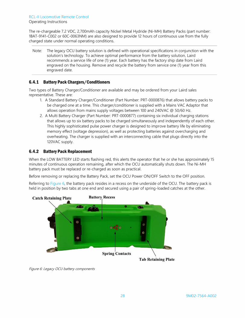
Referring to Figure 6, the battery pack resides in a recess on the underside of the OCU. The battery pack is
held in position by two tabs at one end and secured using a pair of spring-loaded catches at the other.
Figure 6: Legacy OCU battery components

RCL-II Locomotive Remote Control
Operating Instructions
29 9M02-7564-A002
Remove the battery by first releasing the two catches, then lifting the battery pack out of its recess. Battery
pack installation is equally simple: engage the tabs into their locations under the retaining plate, and then
push the battery pack fully home to engage the catches.
Having installed a fresh Battery Pack, set the OCU Power ON/OFF Switch to ON. Before resuming your
remote control operation, momentarily set the TIME/STATUS selector switch to STATUS and observe that the
correct locomotive identifier is indicated on the OCU alphanumeric Status Display. If this condition is met,
your OCU is now fully operational.
To remove a battery pack: Release (push forward) both catches, tilt, and lift the battery pack away from its
recess until the front tabs are completely withdrawn from their recessed locations under the retaining plate.
To replace a battery pack: tilt and position the tabs at the front of the battery pack to engage in their
recessed location sunder the retaining plate. Lower and push the battery pack fully into its recess to engage
the two catches.
6.4.3 Ni-MH Battery Pack Charging
CAUTION:
Laird®
Battery Conditioners are designed for use with Laird®
Battery Packs only.
Battery Packs must be removed or disconnected from Battery Conditioners within 48
hours of achieving the fully charged state.
Failure to comply with these cautions may result in equipment and/or battery damage
and will void our warranty.
The Ni-MH battery pack must be removed from the OCU for external charging.
The standard battery conditioner operates from supply voltages between 100 and 240 VAC @ 50/60 Hz.
Referring to Figure 7, first connect the Conditioner/Charger (PRT- 0000876) to the supplied multi-voltage AC
Adapter as shown.
As with the OCU, the battery pack is installed to the charger/conditioner by first engaging the two tabs into
their recessed locations. The battery pack is then lowered to engage with the two spring contacts before
coming to rest between the battery guides (Figure 8). To remove, lift the battery pack away from the battery
guides, and then withdraw the tabs from their recessed locations on top of the charger/conditioner.
The charger/conditioner automatically conditions the battery pack by first discharging it at 1000mA for 1½
hours before applying a rapid charge for 2 hours. The charger/conditioner incorporates end of charge
detection circuitry to accurately sense when the battery pack is fully charged. When this condition has been
detected, the charger/conditioner switches to a trickle mode that keeps the battery pack fully charged and
ready to use for up to 48 hours. To prevent damage to the battery pack, remove the battery from the
charger/conditioner within 48 hours after achieving a fully charged state.
As shown in Figure 9, the battery charger/ conditioner incorporates an LED that indicates status as follows:
Amber: The battery pack is being discharged.
Red: The battery pack is being charged at a rapid rate.
Green: The battery pack is fully charged and a trickle charge is being applied to maintain the fully
charged state. The battery pack is ready for use and needs removed from the charger/conditioner
within 48-hours.

RCL-II Locomotive Remote Control
Operating Instructions
30 9M02-7564-A002
6.4.3.1 Ni-MH Battery Pack Charging using Standard Charging/Conditioning Unit
Figure 7: Single-bay battery charger
Figure 8: Installing the battery pack on the charger Figure 9: Battery in charging position
6.4.4 Li-Ion Battery Pack Charging
Some legacy OCUs ship with a Li-Ion battery and single-unit charger. Before use, carefully read the
applicable items in the operating instructions included with your battery.

RCL-II Locomotive Remote Control
Operating Instructions
31 9M02-7564-A002
6.4.5 Multi-Battery Charger
Remove the Ni-MH battery pack from the OCU for external charging.
The Multi Battery Charger (part number PRT-0000877) is supplied with an interconnecting cable that plugs
directly into the AC adapter supply.
As with the OCU and Standard Battery Charger/Conditioner, the battery pack is installed to a vacant Multi
Charger location by first engaging the two tabs into their recesses. The battery pack then lowers to engage
with the two spring contacts before coming to rest between the battery guides. Remove the battery by first
lifting the battery pack away from the battery guides, and then withdrawing the tabs from their recessed
locations on top of the charger.
This highly sophisticated battery charger incorporates a four-stage charging sequence: Soft Start, Fast
Charge, Topping Charge, and Maintenance Charge.
1. Soft Start: Gradually increases current levels up to a Fast Charge rate during the first two minutes.
2. Fast Charge: Applies charging current in a series of charge and discharge pulses until the battery
pack is fully charged (typically in one hour).
3. Topping Charge: Applies charging current at a rate low enough to prevent the battery pack from
overheating, yet high enough to ensure a full charge.
4. Maintenance Charge: Applies charging current sufficient to offset the natural self-discharge of a Ni-
MH battery by keeping cells primed at peak charge.
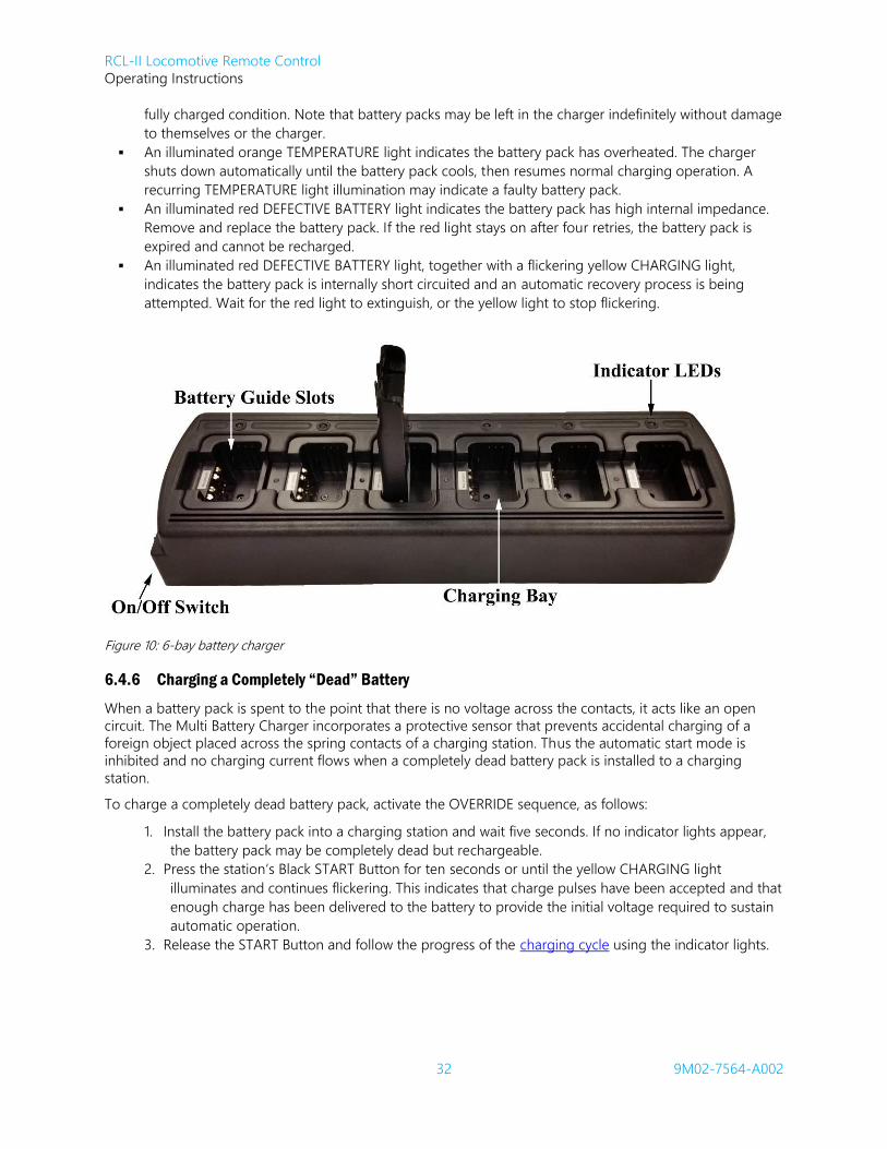
Four Indicator lights are provided at each battery pack charging station to signal the battery pack condition,
as follows:
In normal operation, seconds after the battery pack is installed, the yellow CHARGING light illuminates
and flickers as the battery pack is charging.
Once charging is complete, a blinking green READY light appears. You may now use the Battery Pack,
or leave it in the charger where the automatic Maintenance Charge mode keeps the battery pack in a
RCL-II Locomotive Remote Control
Operating Instructions
32 9M02-7564-A002
fully charged condition. Note that battery packs may be left in the charger indefinitely without damage
to themselves or the charger.
An illuminated orange TEMPERATURE light indicates the battery pack has overheated. The charger
shuts down automatically until the battery pack cools, then resumes normal charging operation. A
recurring TEMPERATURE light illumination may indicate a faulty battery pack.
An illuminated red DEFECTIVE BATTERY light indicates the battery pack has high internal impedance.
Remove and replace the battery pack. If the red light stays on after four retries, the battery pack is
expired and cannot be recharged.
An illuminated red DEFECTIVE BATTERY light, together with a flickering yellow CHARGING light,
indicates the battery pack is internally short circuited and an automatic recovery process is being
attempted. Wait for the red light to extinguish, or the yellow light to stop flickering.
Figure 10: 6-bay battery charger
6.4.6 Charging a Completely “Dead” Battery
When a battery pack is spent to the point that there is no voltage across the contacts, it acts like an open
circuit. The Multi Battery Charger incorporates a protective sensor that prevents accidental charging of a
foreign object placed across the spring contacts of a charging station. Thus the automatic start mode is
inhibited and no charging current flows when a completely dead battery pack is installed to a charging
station.
To charge a completely dead battery pack, activate the OVERRIDE sequence, as follows:
1. Install the battery pack into a charging station and wait five seconds. If no indicator lights appear,
the battery pack may be completely dead but rechargeable.
2. Press the station’s Black START Button for ten seconds or until the yellow CHARGING light
illuminates and continues flickering. This indicates that charge pulses have been accepted and that
enough charge has been delivered to the battery to provide the initial voltage required to sustain
automatic operation.
3. Release the START Button and follow the progress of the charging cycle using the indicator lights.

RCL-II Locomotive Remote Control
Operating Instructions
33 9M02-7564-A002
6.5 Operator Control Unit (OCU-III Model) — Functional Description
OCU-III is designed to be a new generation of Operator Control Unit that merges the best features of legacy
BELTPACK and Accuspeed OCUs. OCU-III uses dual processor architecture and modern electronics to
provide the latest technology in RCL operation with a look and feel that matches the original Accuspeed and
BELTPACK OCU2e OCUs. The unit is lighter in weight than the legacy OCU to provide the RCO with a
portable control that is extremely comfortable and easy to operate, durable, and built for all outdoor
environments. The OCU incorporates an RF transceiver and meets all U.S. FCC and Industry Canada
requirements regarding EMI-RFI human exposure, and of narrow band and 12.5 kHz bandwidths.
OCUs are equipped with an internal antenna and the typical operating range is 1 mile (1600 meters) line of
sight operation. Should the transmitter go out of operating range, the LCU places the locomotive in a Full
Service Penalty.
WARNING:
LOCOMOTIVES SHALL NEVER BE OPERATED UNDER REMOTE CONTROL WITHOUT VISUAL ASSURANCE THAT THE TRANSMISSION (LINE OF SIGHT) PATH IS CLEAR OF OBSTRUCTIONS. FAILURE TO IMPLEMENT THIS WARNING MAY RESULT IN SERIOUS INJURY OR DEATH TO PERSONNEL AND DAMAGE TO EQUIPMENT.
An authorized station operating license is required for the operation of US FCC Part 90 and Industry Canada
RSS-119 (continuous transmission) applications. If you need assistance in obtaining these licenses, please
contact Laird customer support.
RCL-II Locomotive Remote Control
Operating Instructions
34 9M02-7564-A002
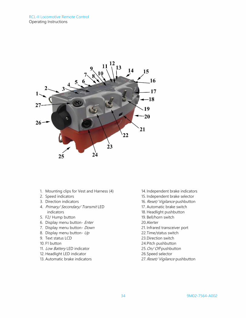
1. Mounting clips for Vest and Harness (4)
2. Speed indicators
3. Direction indicators
4. Primary/ Secondary/ Transmit LED
indicators
5. F2/ Hump button
6. Display menu button- Enter
7. Display menu button- Down
8. Display menu button- Up
9. Text status LCD
10. F1 button
11. Low Battery LED indicator
12. Headlight LED indicator
13. Automatic brake indicators
14. Independent brake indicators
15. Independent brake selector
16. Reset/ Vigilance pushbutton
17. Automatic brake switch
18. Headlight pushbutton
19. Bell/horn switch
20. Alerter
21. Infrared transceiver port
22. Time/status switch
23. Direction switch
24. Pitch pushbutton
25. On/ Off pushbutton
26. Speed selector
27. Reset/ Vigilance pushbutton

35
CAUTION:
The OCU-III uses a polycarbonate housing that is suitable for rugged environments and radio frequency transmission. This plastic is reactive to a number of chemicals and therefore may only be cleaned using a mild soap solution with water, methyl or isopropyl alcohol, heptane, or hexane. No other solutions are approved for use by Laird. Laird is not responsible for damage to devices caused by the use of any other solutions that will void the warranty.
This exterior material WILL BE DAMAGED if exposed to chemicals/ solutions and adhesives commonly found in cleaning products. The chemicals that may cause damage include, but are not limited to: partially hydrogenated hydrocarbons, ketones (such as MEK), strong acids, alkalines (such as sodium hydroxide), or other similar products. Using unauthorized solutions to clean the housing will result in damage and void the warranty.
CAUTION:
OCU and LCU transceivers should NOT be powered “ON” until the antenna is properly
installed. Failure to do so may result in the damage to the unit’s transceiver.
6.5.1 Self-Diagnosis
At power up, the OCU executes many self-tests to ensure that it is in working order to safely control the
locomotive. If the power up self-tests pass, the OCU then displays start up information on the Status Display.
This information is provided to the user to determine if the OCU is assigned to a locomotive.
During operation the self-diagnosis runs constantly. If at any point the OCU detects a system failure it
generates a hardware fault, commands a penalty brake application, and then shuts down. Most hardware
faults are of Full Service Penalty severity. A description of the fault, along with an error code is posted to the
OCU Status Display. The internal Archive Record for the OCU will contain the Hardware Fault and diagnostic
data along with many other informational events.
6.5.2 Low Battery Indication
The OCU incorporates a low battery detection circuit that operates in two separate stages. With a charged
battery pack installed in the OCU, the Low-Battery LED will not be active. As the battery voltage drops the
“Low Battery” LED flashes amber once per second. Every thirty seconds the OCU Status Display will show
“Battery Low”. When this occurs, the OCU remains powered for approximately fifteen minutes. As the charge
level decreases to the next warning level, the OCU flashes the Low Battery LED twice per second and the
OCU Status Display shows “Battery Low” every fifteen seconds. As the level of charge decreases to the final
warning level, the OCU will command Full Service Penalty for five seconds, stop transmitting, and post the
message “Low Battery RF Shutdown” to the Status Display.

RCL-II Locomotive Remote Control
Operating Instructions
36 9M02-7564-A002
6.5.3 Speed Select Lever
This Lever is used to select the desired speed of the locomotive.
Note: The Speed Selection set points indicated below are typical and may not reflect those on your OCU
– your actual speed set points have been factory programmed to suit your requirement and are
fully configurable through BCF.
In order to initiate a speed selection from Stop, the operator must first activate either Reset/Vigilance switch
and then select the desired speed within seven seconds. If the operator fails to select a speed within the 7-
second window, they are required to move the speed lever back to stop and activate either Reset/Vigilance
switch before a speed selection will be accepted.
STOP: Brings locomotive to a controlled stop by returning the throttle to idle and commanding a
full application of the independent brakes.
H1/COAST B: Returns throttle to idle and applies 15 lbs. of independent brake pressure, allowing
the locomotive to gradually come to a stop. Any time the locomotive speed increases, the
independent brakes are proportionally applied to bring the locomotive speed back down. Note that H1
is the optional hump speed #1 when the system is operating in HUMP mode.
H2/COAST: Returns throttle to idle and allows locomotive to coast without brake application.
Any time the locomotive speed increases, the independent brakes are proportionally applied to bring
the locomotive speed back down. Note that H2 is the optional hump speed #2 when the RCL system is
operating in HUMP mode.
H3/COUPLE: LCU automatically adjusts throttle and brake settings to maintain 1 MPH 0.3 MPH.
Note that H3 is the optional hump speed #3 when the system is operating in HUMP mode.
4: LCU automatically adjusts throttle and brake settings to maintain 4 MPH 0.5 MPH.
7: LCU automatically adjusts throttle and brake settings to maintain 7 MPH 0.5 MPH.
10: LCU automatically adjusts thrott,/le and brake settings to maintain 10 MPH 0.5 MPH.
15: LCU automatically adjusts throttle-e and brakes for maximum speed, typically 15 MPH 0.5
MPH.
6.5.4 Independent Brake Override Lever
This Lever is occasionally used by the operator to command an Independent Brake Override Application.
Note: The pressure selection set points indicated below are typical and may not reflect those on your
OCU – your actual pressure set points have been factory programmed to suit your brake
application requirements and are fully configurable through BCF.
The operator can select the following settings:
RELEASE: Releases the independent brakes and places them under control of the LCU for maintaining
the selected speed.
LOW: Applies 1/3 of independent brake pressure.
MEDIUM: Applies 2/3 of independent brake pressure.
HIGH: Applies full independent brake pressure.
EMERGENCY: Commands an Emergency Application of the braking system by venting the brake pipe
to atmosphere, commanding a full application of the independent brakes, and returning the throttle to
idle. Note that in order to command EMERGENCY, the operator must overcome a stiffer detent to
prevent accidental Emergency activation.

RCL-II Locomotive Remote Control
Operating Instructions
37 9M02-7564-A002
IMPORTANT NOTES:
The LCU will never command an independent brake pressure lower than that selected by the
Independent Brake Override Lever.
While the RCL is moving, the use of the IBO is limited (restricted) according to the Independent Brake
Dragging Interlock feature.
6.5.5 Automatic Brake Override Toggle Switch
This three-position toggle switch is occasionally used by the operator to command an Automatic Brake Application. Note that this switch has the following operating positions:
1. Momentarily pushing the switch forwards (away from operator) will toggle a brake selection
towards FULL.
2. Holding the switch away from the operator activates the auto increment feature of OCU-III and will
move the ABO selection toward FULL in steps.
3. Holding the switch in the center maintained position holds the current brake selection.
4. Holding the switch towards operator toggles a brake selection towards RELEASE.
Note: All pressure Settings are client configurable through BCF. Accordingly, the settings indicated below
are typical and may not reflect those on your RCL-II system.
The operator can select the following settings:
RELEASE: Releases the automatic brakes and applies 90 psi to the locomotive brake pipe.
MINIMUM: Commands a 7 psi reduction of the brake pipe.
LIGHT: Commands a 10 psi reduction of the brake pipe.
MEDIUM: Commands a 15 psi reduction of the brake pipe.
FULL: Commands a 20 psi reduction of the brake pipe.
CHARGE: Commands a release of the automatic brakes and fast idles the engine until a sufficient
charge is detected on the brake pipe. Locomotive movement is disabled until a full charge is detected.
IMPORTANT NOTES:
The LCU will never command a brake pipe pressure higher than selected on the AUTOMATIC BRAKE
OVERRIDE TOGGLE SWITCH.
While the RCL is moving, the use of the ABO is restricted according to the Train Brake Cycle Braking
feature.
6.5.6 Direction Select Toggle Switch
This three-position maintained toggle switch is configured as follows:
FORWARD: Selects Forward direction on the locomotive.
NEUTRAL: Selects no direction on the locomotive
REVERSE: Selects Reverse direction on the locomotive.
6.5.7 Headlight Pushbutton
When the system is first switched on, the locomotive headlights will automatically be set to DIM in both
directions. This is a safety feature to prevent accidents when moving the locomotive in low visibility areas.

RCL-II Locomotive Remote Control
Operating Instructions
38 9M02-7564-A002
If the operator wishes to select the headlights to BRIGHT, he or she must momentarily activate the headlight
pushbutton (note that the BRIGHT headlight automatically changes when direction of travel changes).
Momentarily activating the headlight pushbutton again will turn the headlights OFF.
Note: The headlight bright functionality can be used by the RCO as an additional means of verifying that
the RCL Reverser is set in the desired direction.
6.5.8 Tilt [Time] Extend/Status Toggle Switch
This switch is used to request a Tilt Time Extension and to request Status Display information. Details of the
Tilt Time Extend are described in Section 7.7.11.
Note: The Primary and Secondary OCU P & S designators can always be viewed with the Time/Status
Toggle Switch held in the STATUS position, even if a scrolling message is being displayed.
6.5.9 Bell / Horn Toggle Switch
This three-position toggle switch is configured as follows:
BELL/HORN (momentary): Rings the bell and sounds the horn.
BELL (maintained – center): Rings the bell.
OFF (maintained): Turns the bell and horn off.
6.5.10 Reset/Vigilance Switches
Two multiple function toggle switches are used to reset Vigilance timers, acknowledge LCU warnings, and
accept a pitch of control from the Primary OCU. Additionally, when held for longer than five seconds, sand
dispenses in the direction of travel for as long as the switch is depressed.
6.5.11 Power ON / OFF Switch
Used to turn power ON and OFF to the OCU.
Note: At any time during remote control operation, if the OCU does not appear to be functioning
correctly, or the locomotive is not responding as commanded, set the Power ON/OFF Pushbutton
Switch to OFF and remove the Battery Pack.
OCU-III has an improvement over legacy OCUs in the power down sequence. When the power switch on
OCU-III is set to OFF, the OCU transmits a Full Service Penalty command for five seconds before shutting
down. The intent of this improvement is to issue a Full Service Penalty as soon as the OCU is powered off.
6.5.12 Pitch Pushbutton
Used to transfer control from the Primary RCO to the Secondary RCO during the Pitch and Catch procedure.
Also, the BELTPACK feature of clearing OCU assignment by powering up with the Pitch switch active, then
following prompts on the Status Display, is accessed with this switch.
6.5.13 Accelerometer
OCU-III has an accelerometer built into the CPU to detect when the OCU tilts beyond the predefined tilt
angle. This component acts as the monitoring device for the operator Tilt Protection feature.
Another use for the accelerometer is to detect motion. When the system is in hump mode and a hump
speed is selected, the detection of motion consistent with walking and pulling pins will satisfy the vigilance
timer. This was originally a BELTPACK feature that is now part of OCU-III.

RCL-II Locomotive Remote Control
Operating Instructions
39 9M02-7564-A002
6.5.14 OCU Feedback
Each OCU incorporates the exclusive STS feature that provides two-way digital data communication between
the LCU and the OCU. Function LEDs and a text display are located on the top panel of the OCU, which allow
the operator to monitor critical status information being sent from the locomotive. The LEDs confirm the
position of the switches and are bi-color in design.
When the operator commands a function from the OCU, the corresponding LED will indicate that the
command has been read by the OCU and transmitted to the LCU. When the LCU receives and acts upon an
OCU command it transmits a confirmation signal to the OCU, changing the LED color. The confirmation color
varies based on the LED setting. Most of the confirmation colors are green, but to comply FRA Human
Factors Guidelines for RCL Systems (DOT/FRA/ORD-07/19), Stop and Emergency have a confirmation color of
red. This provides a positive conformation to the operator that the command has been received and acted
upon by the LCU during the next Poll sequence.
6.5.15 PC Application
OCU-III MainTerm is a companion PC Application to OCU-III. This program is intended to be the sole
application required for OCU maintenance, programming, configuration, and monitoring. The connection to
MainTerm is either through a serial line located in the battery compartment, or wirelessly through the
Bluetooth interface.
6.5.15.1 Internal Archive Record
The OCU-III firmware maintains an Archive Record in a very similar method as RCL-II. Every time the OCU
detects that an event occurs, it takes a snapshot of all of the system I/O. This data is stored in the Archive
Memory and can be later retrieved and reviewed.
6.5.15.2 Switch Statistics
In addition to the Archive Record that is stored in OCU-III, the number of activations that each switch has
detected is logged. These switch statistics can be reset per switch by an authorized Technician when a switch
is changed.
6.5.15.3 Bluetooth Interface
OCU-III includes a Bluetooth radio. Currently the purpose of this radio is to provide an optional wireless link
for OCU-III MainTerm.
6.5.15.4 GPS Logging
OCU-III also includes a GPS receiver. The GPS health and positional data are part of the data that is stored in
the Archive Record. A separate file that includes only the time-stamped GPS data is also included when the
Archive Record is copied from OCU-III.
6.5.16 Infrared (IR) Transceiver
A transceiver located on the front of the OCU enables an interactive data transfer link to be made between
the LCU and the OCU during IR Assignment.
6.5.17 Audible Warning Device (Alerter)
Audible warnings are provided to alert the RCO of different conditions. Different Alerts are designed to
minimize the amount of attention that the RCO has to pay to the Status Display. The intent is that the RCO
learns what each tone means and can therefore determine if they need to divert their attention to the Status
Display when it is safe to do so.
Single Beep: Successful IR Assignment
Short Double Beep: A new message has posted to Status Display
Long Double Beep: Low Battery warning
Triple Beep: A Hardware Fault of Unsuccessful OCU Assignment

RCL-II Locomotive Remote Control
Operating Instructions
40 9M02-7564-A002
Pulsed Tone: Vigilance Warning
Solid Tone: Tilt Warning
Siren Tone: LCU generated a Penalty and train action is imminent
Note: When the RCO is riding on moving equipment and the OCU generates an Audible Warning, it is
essential that the RCO take heed of this notification. There is a possibility that a System-induced
Fault Stop has been generated and therefore train action is imminent.
6.5.18 OCU Text Status LCD
The OCU-III display is a three-line, sixteen character-per-line display. The first two lines display messages sent
by the LCU with no scrolling required. The third line displays messages local to the OCU (Tilt, Vigilance, Low
Battery, etc.) or status messages commanded by the RCO (speed, brake pressures, etc.).
OCU-III makes all available Status Display Analog Values available for all clients. The available Status Display
Messages are: Loco ID, Speed, Independent Brake Pressure (#20 Pipe), Auto Brake Pressure, Traction Motor
Current, Handbrake State, Airflow and Slug Online Status. Note that the Handbrake Status and Slug Online
Status are only available if the RCL-II Decoder has the features activated in the BCF file. Otherwise, these
Status Display indices are not visible.
6.5.19 Primary/Secondary Indication LED
In order to free space on the Status Display, OCU-III displays PRI/SEC status through designated LEDs on the
membrane.
6.5.20 OCU-III Battery Pack Chargers
Laird’s rechargeable 7.4V, 5600 mAh capacity Lithium-ion battery (Li-Ion) (part number: 1BAT-8437-A001) is
manufactured to high physical tolerances that ensures a secure fit with the OCU-III battery compartment, as
well as being designed to provide 8-hours of continuous use from the fully charged state, with temperatures
as low as -20C/-4F.
The OCU-III chargers are designed in conjunction with the Li-Ion battery and other chargers are not
compatible with this battery. The chargers are available in both a Single Bay Unit (1PRT-8449-A001) and a Six
Bay Unit (1PRT-8451-A001) configuration.
Figure 11: OCU-III Single Bay Unit Figure 12: OCU-III battery charging in Six Bay Unit

RCL-II Locomotive Remote Control
Operating Instructions
41 9M02-7564-A002
Figure 13: OCU-III Six Bay Unit battery charger
The chargers ship standard with a Power Supply Unit, North America adapter, and a User Manual.
Note: Please reference the battery charger User Manual supplied with your battery pack for additional
details for both the Single Bay Unit (1PRT-8449-A001) and Six Bay Unit (1PRT-8451-A001) chargers.
6.5.21 OCU-III Battery Pack Replacement
When the LOW BATTERY LED starts flashing red, this alerts the operator that he or she has approximately 15
minutes of continuous operation remaining, after which the OCU-III automatically shuts down. The battery
pack must be replaced or recharged as soon as practical.
Before removing or replacing the Battery Pack, set the OCU Power ON/OFF Switch to the OFF position.
Referring to Figure 14, the battery pack resides in a recess on the underside of the OCU-III. The battery pack
is held in position by tabs at one end and secured using a spring-loaded catch.
Note: The OCU-III battery solution is defined with operational specifications in conjunction with the
solution’s technology. To achieve optimal performance from the battery solution, Laird
recommends a service life of one (1) year. Each battery has the factory ship date from Laird
engraved on the housing. Remove and recycle the battery from service one (1) year from this
engraved date.
Figure 14: Battery Pack location (underside of OCU-III)

RCL-II Locomotive Remote Control
Operating Instructions
42 9M02-7564-A002
6.6 Reflective Safety Vest
Operators are to wear a reflective safety vest or similar approved carrying device at all times when operating
the OCU. The Reflective Safety Vest (Part Number 42C-0078) is designed to comfortably support the OCU.
This item incorporates multiple anchor mounting catches for user preference, a front zipper pouch to store
spare battery packs, and a retaining loop to hold a 2-way radio microphone.
The vest is supplied in two halves that are held together with Velcro strips at the shoulders. This allows the
vest to be quickly discarded in an emergency, and also to accommodate operators of varying heights. The
vest is worn as shown and secured around the waist using two snap connectors on either side of the rear half
that snap into corresponding receptacles on the front half. Waist adjustment is accomplished by tightening
the two adjustment straps as necessary.
The vest provides three separate mounting locations for the OCU. The operator selects the most comfortable
operating location and secures the OCU to the vest using the appropriate anchor mounting catches.
Figure 15: Reflective Safety Vest
6.7 External Event Recorder Option
A Solid State Recording System is available as an option for radio controlled locomotive applications. The
system will monitor and record electrical analog and digital inputs and pneumatic inputs from the
locomotive along with serial data from the LCU.
All of the above recorded data may be retrieved and downloaded to a laptop computer by way of a direct
serial link onboard the locomotive or by a Cellular Modem Interface.
Three software programs are supplied with the Event Recorder, as follows:

RCL-II Locomotive Remote Control
Operating Instructions
43 9M02-7564-A002
Data Analysis Program
Locomotive Download Program
Verifier Program
The Data Analysis and Locomotive Download Programs are both 32-bit Microsoft Windows®
based and are
tied together (the recording system can be downloaded through the Data Analysis Program). The programs
can also be used separately. The Locomotive Download Program makes an exact copy of the data stored in
the event recorder and stores it to either a laptop computer hard drive or floppy disk. The Data Analysis Program interprets and analyzes the downloaded data in graphical or tabular format. The Verifier Program
allows near real-time monitoring of a specific locomotives operations. With this program, the data that is
stored in the Event Recorder is available “live”.
6.7.1 System Components
Solid State Event Recorder that contains the system electronics, including pneumatic, analog, and
digital sensors.
Main Recorder Cable that connects the Event Recorder to the locomotive.
RS-232 RCL-II Decoder Cable connects the event recorder to the LCU.
Serial Download Interface Port (locomotive cab mounted enclosure) incorporating a DB9 connector
that enables data downloads to be carried out using a laptop computer.
Traction Motor Current Module to monitor Traction Motor Current.
6.7.2 Pneumatic Connections
Brake Pipe - monitors the analog brake pipe pressure in psi. The port is labeled BK PIPE.
Brake Cylinder - monitors the analog brake cylinder pressure in psi. The port is labeled BC GAUGE.
Horn - can be connected pneumatically or electrically, but not both. Typically the pneumatic
connection is used. The port is labeled HORN and inputs are recorded with a resolution of 1/10th
of a
second while all other inputs are recorded with a one second resolution.
Bell - can be connected pneumatically or electrically, but not both. Typically the pneumatic connection
is used.
6.7.3 Digital Inputs
Throttle Position – The state of the throttle position is recorded along with the generator field used to
determine throttle position.
Dynamic Brake Setup – This input is recorded and displayed as part of the throttle notch position
channel.
Generator Field – This input is recorded as one of the inputs for throttle position.
Direction of Travel (Forward, Neutral, and Reverse positions) – Two inputs are used for this channel.
One of the inputs monitors the forward line (MU-8) while the other input monitors the reverse line
(MU-9).
Horn – This input is recorded as a high-resolution event with a resolution of 1/10th
of a second. This
input can be either connected pneumatically or electrically, but not both. Typically the pneumatic
connection is used.
Bell – This input can be either connected pneumatically or electrically, but not both. Typically the
pneumatic connection is used.
PCS Open – This input is used to monitor the Power (Pneumatic) Control Switch. This recorded input is
used to determine whether an emergency condition occurred.
Spare I/O Input – This input can be used to monitor a 74V digital input.

RCL-II Locomotive Remote Control
Operating Instructions
44 9M02-7564-A002
6.7.4 Analog Inputs
Speed – What is actually recorded is rotational speed (RPM). This measurement, wheel size, and time
data are used to determine distance traveled and speed. This input is connected to either a 20- or 60-
pole axle drive.
Traction Motor Current (Load Amps) – This input is connected to the Traction Motor Current Module
type CM-03.
6.7.5 Serial Inputs
The event recorder system monitors and records serial data from the RCL-II decoder. All serial data is
recorded with a resolution of one second.
6.7.6 Recorder Functionality
All inputs are recorded with a one second resolution, except for the Horn, which is recorded with a tenth of a
second resolution. The system records a minimum 96 hours of data before re-recording over the oldest
stored data (endless loop). The recorder utilizes Flash Data Memory (no batteries are required to maintain
data integrity) to store the event data.
6.8 Cellular Modem Interface Option
Incorporating a Cellular Modem Interface into the system allows data to be viewed or retrieved remotely
from virtually anywhere a network connection is available. Such wireless integration is accomplished by
interfacing RCL-II and the existing Event Recorder with a multi-mode cellular modem.
The multi-mode cellular modem assembly contains rugged extended temperature hardware modules that
support the CDMA and GSM infrastructures.
Note: It is the responsibility of the end user to obtain a service contract from a cellular provider.
Accordingly, the end user is fully responsible for all registration and airtime fees associated with
implementation and use.
Each Cellular Modem Interface is assigned a unique telephone number and needs referenced by the
Locomotive ID to which it is installed. Instant verification of the Locomotive ID can be made once a
connection is established by using the recovered data.
The Cellular Modem Interface may be used to pull the internal RCL-II Archive Memory or download new
operating parameters into the LCU with the Laird proprietary software Maintenance Terminal, or to remotely
access the external event recorder with the Event Recorder software.
6.8.1 System Components
The Cellular Modem Interface consists of a NEMA 12 enclosure that houses the following items:
Communication Interface PCB
Cellular modem (CDMA or GSM digital)
72-12V DC-DC converter
Interconnect cabling
Antenna Input TNC (female) connector for connection to Antenna cable TNC (male) connector
Connector for the Maintenance Terminal

RCL-II Locomotive Remote Control
Operating Instructions
45 9M02-7564-A002
The following items may also be supplied with the system:
3dB Gain Dual Band Whip Antenna with 15 feet of coaxial cable and TNC (male) connector
Patch Cable to connect from DATA Input Socket on Cellular Modem Interface (CMI) to DOWNLOAD
socket on Event Recorder
DC input cable assembly
Interface Plate and hardware for mounting the CMI Enclosure to the Event Recorder
6.8.2 Cellular Telephone Service
In the United States, the main nationwide service providers to consider for CDMA are Verizon or AT&T for
GMS. A connection is also available for secure Wi-Fi connection.
6.9 Remote Display Option
In many cases the locomotive cab has limitations for size and location of RCL equipment. This may cause
difficulty finding an acceptable location for the RCL equipment that still permits the RCO to access the points
of the system that they are required to interface with on a daily basis. The Remote Display option resolves
this issue by providing a small enclosure that can be installed on the outside of the electrical locker. This
enclosure provides access to the Manual/Remote and Menu buttons that are otherwise installed on the front
panel of the OCU. The LCU display and IR Assignment port are also located on the Remote Display. This
option allows the bulk of the RCL equipment to be installed in locations that are not frequented by
Operations Personnel.
6.9.1 Option Kit Components
Remote Display Panel
Electrical Isolation PCB
Interconnect Cabling
6.10 Brake Interface Options
One of these three options is required for the RCL-II system to control the locomotive and train brakes.
6.10.1 26-L Brake Interface
The RCL-II system can be configured to interface with 26-L Brake systems through our Relay/Pneumatic
Interface. With this configuration, the RCL system pneumatically controls the brake as if the RCL was a lead
unit.
6.10.2 CCB-26 Electronic Brake Interface
The RCL-II system can be configured to interface with CCB-26 Electronic Brake systems through a smaller
version of the Relay/Pneumatic Interface. With this configuration, the RCL system controls the brakes as if the
RCL was a lead unit electrically through nodes on the CCB-26 system. The RCL system has control of its own
failsafe valves for Independent and Train Brake as a backup to a failure in the electrical link.
6.10.3 FastBrake Electronic Brake Interface
The RCL-II system can be configured to interface with FastBrake Electronic Brake systems from a single
enclosure. With this configuration, the RCL system controls the FastBrake system through a serial link. The
RCL system has control of its own failsafe valves for Independent and Train Brake as a backup to a failure in
the serial link.
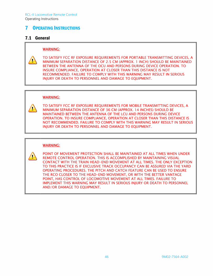
RCL-II Locomotive Remote Control
Operating Instructions
46 9M02-7564-A002
7 OPERATING INSTRUCTIONS
7.1 General
WARNING:
TO SATISFY FCC RF EXPOSURE REQUIREMENTS FOR PORTABLE TRANSMITTING DEVICES, A MINIMUM SEPARATION DISTANCE OF 2.5 CM (APPROX. 1 INCH) SHOULD BE MAINTAINED BETWEEN THE ANTENNA OF THE OCU AND PERSONS DURING DEVICE OPERATION. TO INSURE COMPLIANCE, OPERATION AT CLOSER THAN THIS DISTANCE IS NOT RECOMMENDED. FAILURE TO COMPLY WITH THIS WARNING MAY RESULT IN SERIOUS INJURY OR DEATH TO PERSONNEL AND DAMAGE TO EQUIPMENT.
WARNING:
TO SATISFY FCC RF EXPOSURE REQUIREMENTS FOR MOBILE TRANSMITTING DEVICES, A MINIMUM SEPARATION DISTANCE OF 36 CM (APPROX. 14 INCHES) SHOULD BE MAINTAINED BETWEEN THE ANTENNA OF THE LCU AND PERSONS DURING DEVICE OPERATION. TO INSURE COMPLIANCE, OPERATION AT CLOSER THAN THIS DISTANCE IS NOT RECOMMENDED. FAILURE TO COMPLY WITH THIS WARNING MAY RESULT IN SERIOUS INJURY OR DEATH TO PERSONNEL AND DAMAGE TO EQUIPMENT.
WARNING:
POINT OF MOVEMENT PROTECTION SHALL BE MAINTAINED AT ALL TIMES WHEN UNDER REMOTE CONTROL OPERATION. THIS IS ACCOMPLISHED BY MAINTAINING VISUAL CONTACT WITH THE TRAIN HEAD-END MOVEMENT AT ALL TIMES. THE ONLY EXCEPTION TO THIS PRACTICE IS IF EXCLUSIVE TRACK OCCUPANCY CAN BE ASSURED VIA THE YARD OPERATING PROCEDURES. THE PITCH AND CATCH FEATURE CAN BE USED TO ENSURE THE RCO CLOSER TO THE HEAD-END MOVEMENT, OR WITH THE BETTER VANTAGE POINT, HAS CONTROL OF LOCOMOTIVE MOVEMENT AT ALL TIMES. FAILURE TO IMPLEMENT THIS WARNING MAY RESULT IN SERIOUS INJURY OR DEATH TO PERSONNEL AND/OR DAMAGE TO EQUIPMENT.
RCL-II Locomotive Remote Control
Operating Instructions
47 9M02-7564-A002
7.2 Locomotive Transfer from Manual to Remote Control
WARNING:
THE LOCOMOTIVE 3-WAY TRANSFER VALVE MUST BE SECURED WITH A LOCKING PIN OR PADLOCK IN BOTH THE REMOTE AND MANUAL POSITIONS. FAILURE TO IMPLEMENT THIS WARNING MAY RESULT IN THE LOSS OF BRAKES, WHICH IN TURN MAY RESULT IN SERIOUS INJURY OR DEATH TO PERSONNEL AND DAMAGE TO EQUIPMENT.
Note: The Transfer procedures described below reflect a typical RCL-II system. Accordingly, we
recommend you review the customized drawing package provided with your remote control
system to establish the exact location and configuration of all Transfer Valves and Switches as they
apply to your specific locomotive installation.
The general procedure for transferring the Locomotive from MANUAL to REMOTE control is as follows:
1. Configure the locomotive for trailing operation.
2. Transfer the air system to REMOTE using the 3-way transfer valve.
3. Secure the Transfer Valve Lever in this position using a locking pin.
4. Set the REMOTE/MANUAL switch on the front door of the LCU or on the optional Remote Display
to REMOTE.
Note: When transfer to REMOTE control occurs, an Emergency Brake Penalty will be
commanded. Operators will be required to perform the Emergency Brake Recovery
Procedure before starting remote control operations (refer to Brake Recovery
Procedures).
5. Invoke the OCU Assignment Process to directly activate and program the operating parameters to
the PRIMARY and SECONDARY (if desired) OCUs using the LCU Infrared link. Note that if the
system is equipped with the optional Remote Display then the IR assignment can only occur at the
Remote Display.
6. Proceed with remote locomotive control.
RCL-II Locomotive Remote Control
Operating Instructions
48 9M02-7564-A002
7.3 Locomotive Transfer from Remote to Manual Control
WARNING:
THE LOCOMOTIVE 3-WAY TRANSFER VALVE MUST BE SECURED WITH A LOCKING PIN OR PADLOCK IN BOTH THE REMOTE AND MANUAL POSITIONS. FAILURE TO IMPLEMENT THIS WARNING MAY RESULT IN THE LOSS OF BRAKES, WHICH IN TURN MAY RESULT IN SERIOUS INJURY OR DEATH TO PERSONNEL AND DAMAGE TO EQUIPMENT.
Note: The Pneumatic Transfer Valve includes connectivity to a Quick Exhaust Valve that ensures the host
locomotive experiences an Emergency Brake application whenever the Transfer Valve switches
from the REMOTE to MANUAL position. This is the last action taken by the Transfer Valve/Quick
Exhaust before the RCL-II pneumatic sub-system is isolated from the host locomotive pneumatics.
The general procedure for transferring the Locomotive from REMOTE to MANUAL control is as follows:
1. Set the REMOTE/MANUAL switch to MANUAL.
2. Transfer the air system to MANUAL using the 3-way transfer valve.
3. Secure the Transfer Valve Lever in this position using a locking pin.
4. Configure the locomotive for lead operation.
5. Proceed with manual locomotive control.
7.4 Brake Recovery Procedures
Recovery Procedures must be performed in order for the operator to regain movement permission after a
system-generated Fault Stop.
A Fault Stop imposes a brake application and disables any tractive effort. Before movement permission is
restored, the system must recognize the required Recovery Procedure.
Note: The operator must understand which type of recovery is required. Following the directions for
each type of recovery ensures that the RCO saves time and air needed to recharge the brake pipe.
Note: The term “Recover” implies that the Reset Safety Brake Recovery is required, while the term
“Release” implies that only the Brake Selector is involved.
7.4.1 Recover Service Penalty
When the system talkback shows the active LED is STOP while any other speed is selected, the system has set
the speed command to STOP and has applied Full Independent Brakes.
To recover from a Service Penalty:
1. Ensure the locomotive is stationary.
2. Set the controlling OCU controls to correspond with the locomotive condition by moving the Speed
Selector to STOP position.
3. The OCU Command will now be in agreement with the LCU.
You are now ready to resume operations.
Note: The Secondary OCU never has to perform this procedure.
RCL-II Locomotive Remote Control
Operating Instructions
49 9M02-7564-A002
7.4.2 Recover Full Service Penalty
When the OCU Status displays Recover FS Brake, the system has set the speed command to STOP and
applied Full Train Brake.
To recover from FS Penalty the operator(s) must verify which OCU should recover first, as some faults only
require the Primary OCU to recover and some require both OCUs to recover. This information is on the OCU
Status display. After this is determined, the operator that has the OCU that requires recovery should:
1. Ensure locomotive is stationary.
2. Set the OCU controls to correspond with the locomotive condition by:
a. Moving the Speed Selector to STOP position (this OCU Command is now in agreement with
the locomotive).
b. Moving or ensuring Auto Brake Selector is at the Full position, confirmed by Full position
LED being ON (this OCU Command is now in agreement with the locomotive).
3. Activate either Reset/Vigilance switch for greater than one second but fewer than three seconds.
4. Operator decision (Chose one of the following actions);
a. Stay with Train Brake Recovery.
i. Proceed with Steps 5 & 6.
b. Use Charge feature (i.e. do a recovery while cutting in cars).
i. See Brake Pipe Charge Feature. Pay particular attention to Prerequisites and
Sequence of Operation.
5. Move Auto Brake Selector towards REL (Release) within five seconds of activating the
Reset/Vigilance switch.
a. Auto Brake REL position LED turning green confirms the action as the system starts charging
the Brake Pipe.
b. Operator recovery task is now complete
You are now ready to resume operations.
7.4.3 Recover Emergency Penalty
When the OCU Status displays ‘Recover EMG Brake’, the system has set the speed command to STOP as well
as applied Emergency Brake.
To recover from EMG Penalty the operator(s) must verify which OCU should recover first, as some faults only
require the Primary OCU to recover and some require both OCUs to recover. This information will be on the
OCU Status display. After this is determined, the operator with the OCU that requires recovery should adhere
to the following steps.
To recover from Emergency:
1. Ensure locomotive is stationary.
2. Set the Controlling OCU controls to correspond with the locomotive condition by:
a. Moving the Speed Selector to Stop position (this OCU Command is now in agreement with
the locomotive).
b. Confirm or Move Independent Brake Selector to the Emergency position (this OCU
Command is now in agreement with the locomotive).
3. Activate either Reset/Vigilance switch for greater than one second but fewer than three seconds.
4. Move Independent Brake Selector to the REL position within five seconds of pressing the
Reset/Vigilance switch.
a. Independent Brake Full position LED turning green confirms the action.

RCL-II Locomotive Remote Control
Operating Instructions
50 9M02-7564-A002
5. Operator decision (chose one of the following actions):
a. Stay with Emergency Recovery
i. Proceed with Step Six
b. Use Charge feature (i.e. do a recovery while cutting in cars)
i. See Brake Pipe Charge Feature. Pay particular attention to Prerequisites and
Sequence of Operation.
6. Move Auto Brake selector towards REL (Release).
a. Auto Brake REL position LED turning green confirms the action as the system starts
charging the Brake Pipe.
b. Operator recovery task is now complete.
You are now ready to resume operations.
7.5 Locomotive Remote Control – General Operating Guidelines
Note: The following guidelines are of a general nature and should not be substituted for the operational
procedures applicable to your rail yard or locomotive application.
Perform all locomotive tests at the start of your shift according to the locomotive manufacturer’s operation
manual. Do not proceed unless the locomotive is operating satisfactorily according to the manufacturer’s
instructions.
WARNING:
ALL REMOTE OPERATED LOCOMOTIVES SHALL HAVE AUDIO OR VISUAL ALARM/WARNING INDICATIONS WHICH MEET APPROPRIATE GOVERNMENTAL REQUIREMENTS. FAILURE TO IMPLEMENT THIS WARNING MAY RESULT IN SERIOUS INJURY OR DEATH TO PERSONNEL AND DAMAGE TO EQUIPMENT.
WARNING:
LOCOMOTIVES SHALL NEVER BE OPERATED UNDER REMOTE CONTROL WITHOUT VISUAL ASSURANCE THAT THE TRANSMISSION (LINE OF SIGHT) PATH IS CLEAR OF OBSTRUCTIONS. FAILURE TO IMPLEMENT THIS WARNING MAY RESULT IN SERIOUS INJURY OR DEATH TO PERSONNEL AND DAMAGE TO EQUIPMENT.
1. Carry out the OCU Assignment Process – Refer to Section 7.6.2.
2. With the OCU(s) powered on, observe the following:
a. The green transmit LED flashes each time the OCU transmits when the battery has an
adequate charge.
b. When the battery starts to go low, the Low Battery LED flashes with each transmission and
the OCU Status Display indicates the low battery condition. When this happens, there are
approximately fifteen minutes of continuous operating time remaining. Change or recharge
the battery pack as soon as possible.
c. OCU Status Display indicates LINKED AS OCU A FOR XX1234, where XX equals the railroad
identifier and 1234 equals the locomotive number.

RCL-II Locomotive Remote Control
Operating Instructions
51 9M02-7564-A002
Note: When a Secondary OCU has been linked to the LCU, its Status Display indicates
LINKED AS OCU B FOR XX1234.
d. Individual OCU Status Displays then change to indicate Primary OCU and Secondary OCU
designations.
3. Perform an Emergency Recovery procedure. If two OCUs are assigned, the Secondary must
perform the recovery first. The OCU Status Display provides prompts to assist with process.
4. Perform all required preoperational safety checks in accordance with your Railroads operating
requirements. Some examples are:
a. Check each brake function independently to be sure the locomotive is responding correctly
to all brake applications, including emergency stop and release commands. Observe
gauges in the cab for proper readings and verify that the brake cylinders are moving
properly.
b. Check all auxiliary equipment, such as bell, headlight, sanders, etc.
In addition:
Report all defective or missing safety equipment, and mechanical or electrical defects to your
supervisor without delay. Do not continue operation until fully repaired.
When ready to move the locomotive for the first time, proceed slowly and make certain the load is
under control.
Take the slack out of the couplers gradually and make sure hands and other objects are clear before
commanding movement.
Keep all parts of the body away from the rolling equipment and never walk on the tracks ahead of the
train.
Do not move the locomotive if anyone is in a position to be injured.
If anyone is in the path of travel, stop and sound the horn. Do not proceed until the tracks are clear.
When leaving the locomotive unattended for any reason, be sure the locomotive throttle is set to IDLE
and the brakes are fully applied. Set the OCU Power Switch to the OFF position and apply locomotive
hand brake.
Do not allow any unauthorized person to operate the OCU.
7.6 Standard Features
7.6.1 Speed Control
RCL-II is a Speed Control System which indicates that the System has applied the IND Brake if and when
required. The OCU IND Brake Selector should therefore only be considered as an Override function, whereby
the RCO can use this Selector if it appears the RCL is not responding as expected.
Note: The RCO must remain vigilant over the movement of the RCL. If at any time the RCO detects that
the RCL is not responding as expected, it is his/her responsibility to take evasive action by
commanding a STOP. Refer to RCO Evasive Action.
7.6.1.1 Locomotive Speed Control
The Speed Control Algorithm is designed as a compromise between train action and response times when
responding to Speed Set Point change commands. For any given movement command, the Speed Controller
has no knowledge of the number of cars being moved. In situations of extreme train length, the RCO can
mitigate resulting train action by initiating and maintaining movement at a moderate speed (example:
COUPLE) and waiting for train slack to be adjusted before commanding higher Speed Set Points.

RCL-II Locomotive Remote Control
Operating Instructions
52 9M02-7564-A002
7.6.1.2 Independent Brake Override
The RCL-II System is a Speed Control product that automatically applies the required amount of Independent
Brake according to the demanded speed and the current measured speed of the RCL. The OCU provides an
Independent Brake Override (IBO) Control to be used only in special circumstances.
The use of the IBO selector is neither required nor recommended for simple Speed reduction/ Stop
commands. The RCL-II Speed Controller has full control of the Independent Brakes within a Speed
reduction/Stop command, and applies progressive braking accordingly.
However, one need for IBO application is prior to an upgrade movement, where release of the brakes would
cause roll back. In this situation, IBO can be applied to allow the locomotive to build up power against the
brake, and then the operator can release the IBO without rollback occurring. Note that applying brakes using
the IBO selector will command the RCL to apply more brakes than already set by the Speed controller, but
never less.
7.6.1.3 Gradual Speed Reduction
Railway rules dictate that Trains or Engines must move at a speed that allows them to stop within half the
range of vision.
In applying this rule to RCL-II operations it is recommended that any critical STOP (involving movement
approaches to rolling stock, garage doors, switches etc.) be preceded by the gradual (sequential) reduction
of the OCU Speed lever through each successive setting to reach STOP at the required target point. Each
reduction of Speed setting must be performed by the RCO at the (distance) point of compliance with the
Rule. In other words, it is not recommended to go from a Speed setting direct to STOP with the Speed lever.
Note: Follow this procedure to ensure a safety margin should there be radio communication loss during
movement.
7.6.2 OCU Assignment
This process enables the LCU to assign all operating parameters to the OCUs by way of an infrared link. This
ensures that an assigned OCU can communicate with only one LCU, and conversely that the LCU can
communicate with only one OCU A and only one OCU B.
As long as an OCU is assigned to the LCU, it indicates the assigned RCL running number on the OCU Status
Display on power up and when requested with the OCUs Status Switch.
To program the operating parameters to the OCU(s), invoke the OCU Assignment Process on the LCU as
follows:
1. Press and hold the FUNCTION/NO pushbutton located on the front door of the LCU or on the
optional Remote Display for five seconds. After this pushbutton is depressed, the RCL status
display will indicate PROGRAM PRIMARY OCU? – PRESS YES OR NO.
Note: If no response is received by the LCU in 30 seconds, or if the FUNCTION/NO
pushbutton is pressed again, the system will exit the menu and clear any previously
stored OCU addresses.
2. When you are ready to program the PRIMARY OCU, press the YES/ALARM RESET pushbutton once.
The RCL status display will indicate that the system is ready to start the procedure.

RCL-II Locomotive Remote Control
Operating Instructions
53 9M02-7564-A002
3. Set the OCU power switch to ON while holding the right VIGILANCE switch. Observe that the OCU
text status display reads IR LINK.
Note: For OCU-III, holding either VIGILANCE switch on power up prompts the OCU to
start the IR Assignment process. Once the OCU Status Display shows “IR Link -
Release Vigilance”, releasing the vigilance switch causes the OCU to enter IR
Assignment mode. Keeping the vigilance switch active for five seconds causes the
OCU to boot normally with the previously assigned parameters.
4. Align and hold the OCU within three feet of the infrared transceiver. Note that if the system is
equipped with the optional Remote Display, the IR assignment can only occur at the Remote
Display.
Note: If no response is received from the OCU in this span of time, the LCU status display
shows the message IR LINK UNSUCCESSFUL and the system will exit the menu and
clear any previously stored OCU addresses.
5. If the LCU status display indicates TURN OCU POWER OFF, set the Primary OCUs power switch to
off and withdraw the unit.
6. Observe the LCU status display which indicates: PROGRAM SECONDARY OCU? – PRESS YES OR NO.
If you do not wish to program a Secondary OCU, you have two (2) minutes to press the
FUNCTION/NO pushbutton once. Only the Primary OCU will be able to control the locomotive. If
no response is received to this prompt, the LCU clears previously stored OCU addresses and will
not recognize previously linked OCUs.
7. When you are ready to program the Secondary OCU, press the YES/ALARM RESET pushbutton
once. The RCL status display indicates that the system is ready to start the procedure.
8. Repeat the previously listed steps for IR Assignment to assign the Secondary OCU.
7.6.3 Pitch and Catch
Pitch and Catch permits a two-person team to direct movements of one locomotive. Two operators each
carry an OCU that can be used to control the locomotive. One operator at a time may act as the operator in
control or the Primary OCU operator. The Primary OCU operator has the ability to direct all functions of the
RCL or pass control to the Secondary OCU operator. The operator at the leading end of the train (the point)
is typically the Primary OCU operator. The Secondary OCU operator has the ability to control the horn, bell,
and emergency brake only. Both operators are protected by the OCU internal tilt switch and therefore both
operators can request a Tilt Time Extend.
7.6.3.1 Pitching Control
This procedure is best accomplished when both operators are in verbal communication with each other via
their 2-way radios. We recommend that the operator initiating the pitch (the current Primary Operator) carry
out the following instructions while verbally communicating each instruction to the Secondary Operator.
Upon receipt of each instruction, the Secondary Operator is required to act on the instruction before
confirming to the Primary Operator that the step was completed.
Procedure:
1. Both operators verify that the locomotive is completely stopped prior to starting the Pitch and
Catch process.
2. Both OCUs must have the Speed Select lever set to STOP and the Reverser centered. Independent
and Train Brake settings for both OCUs must match.
RCL-II Locomotive Remote Control
Operating Instructions
54 9M02-7564-A002
3. Primary OCU operator activates PITCH pushbutton, then advises Secondary OCU operator that a
Pitch has initiated.
4. Secondary OCU operator accepts the pitch by pressing either Reset/Vigilance switch and confirms
to the Primary OCU operator.
5. Once the Secondary OCU operator accepts the pitch, both OCU displays change to indicate their
new roles, as the OCU that was previously Secondary is now Primary.
Note: If the Secondary OCU operator does not accept the pitch within ten seconds, the pitch initiation
routine times out and the Primary OCU operator remains in full control.
Also note that a feature exists that is intended to reduce accidental pitch requests. If desired, the
system can be configured to require an activation of the Reset/Vigilance switch within five seconds
of the Primary activation of the Pitch switch for the Pitch request to be granted.
7.6.4 Tilt Protection
When the OCU is tilted more than 45 15 past upright, it sends a command to the LCU which, in turn,
commands an emergency brake application, returns throttle to idle, and activates the remote man down
synthesized voice transmitter. When the OCU tilts beyond specified limits for one second, the OCU begins
emitting an audible warning, alerting the operator that they are about to enter into a tilt penalty. If the
operator does not return the OCU to an upright position within 5 seconds from the time the warning sounds,
the shutdown command sends to the LCU. The alert tone is accompanied by a text message to confirm
action necessary to the operator. The tilt components are rugged, reliable, and designed to detect any fault
conditions. To allow for situations where the operator must intentionally tilt beyond the point of tripping the
alarm, a Tilt Time Extend request allows an extension of the tilt timer. The design will not permit maintaining
this switch for an indefinite period of time. Configuration options for this feature will be described in a
subsequent section of this manual.
The Man Down alarm utilizes a Synthesized Voice Talker connected to the Locomotive radio channel that
matches the currently utilized 2-way radio communication network frequency.
WARNING:
BEFORE OPERATING THE RCL SYSTEM, OPERATORS MUST ENSURE THE CORRECT 2-WAY RADIO COMMUNICATIONS NETWORK FREQUENCY CHANNEL IS SELECTED, AND THAT THE LOCOMOTIVE SYNTHESIZED VOICE TALKER HAS BEEN TESTED AND IS FULLY OPERATIONAL ON THIS CHANNEL. FAILURE TO IMPLEMENT THIS WARNING MAY RESULT IN SERIOUS INJURY OR DEATH TO PERSONNEL AND DAMAGE TO EQUIPMENT.
Once activated by the LCU, the Man Down alarm broadcasts a distress message over the 2-way radio
communication network. This message repeats until the operator recovers from the penalty or after 10
minutes have lapsed. Typically, the broadcast alarm message includes the locomotive call sign and identifies
which OCU entered a tilt condition (Operator A or Operator B).
Refer to Brake Recovery section for instructions on how to recover from an Emergency Brake Penalty.

RCL-II Locomotive Remote Control
Operating Instructions
55 9M02-7564-A002
7.6.5 Direction of Movement Protection
Direction
For RCOs, determining direction is a relative term. It is determined by observing the RCL orientation, and is
defined as giving the same direction commands that he/she would give using the locomotive Control Stand.
OCU Forward is equivalent to Locomotive Forward. Therefore, RCOs must always be conscious of the
locomotive/track orientation for true direction commands. Should you change yourself around, DO NOT
assume that direction is in accordance with the way you are facing.
Direction Changes
Supervisory logic protects against inadvertent reverser changes from causing unexpected direction of
movement. Only direction selector changes made under prerequisite conditions are relayed to the reverser
switchgear interface.
Prerequisites for reverser changes:
RCL is NOT in motion.
OCU Speed Selector is at STOP position.
Operating Procedures
In compliance with the Prerequisites, select the desired direction of movement with the Direction Selector,
noting that moving the Direction Selector while the RCL is in motion or has been throttling will evoke Out of Correspondence detection.
As with conventional locomotive operations, RCOs must wait for the RCL to come to a complete STOP
before changing the OCU Direction Selector.
The OCU design seeks to guard mechanically against accidental operation of the Direction Selector; however,
software control safeguards mask unintentional operations by the Out of Correspondence Detection.
Out of Correspondence Detection
Terminology
Out of Correspondence is the term applied to any control device monitored in a non-logical position with
respect to logical conditions and rules.
Example
Changing the OCU Direction Selector while the RCL is moving is a non-logical condition that is declared an
Illegal Reverser Change.
Control Response to Illegal Reverser Change
If the Direction Selector is changed inadvertently or otherwise during an RCL movement, an Out of
Correspondence condition occurs. RCL-II is designed to protect against equipment damage due to this
illogical command with the following response: Continue motion until RCO commands Stop. At this point,
the system will not permit the RCO to command movement until the reverser is set to Neutral and then a
direction is selected.
Note: Many Railroads instruct their RCOs to center the OCU direction selector whenever the RCL is
stationary. Under such conditions the Out of Correspondence is automatically cleared.
Always be cautious and check that the Direction Selector is set for the direction intended before
attempting to move the locomotive.

RCL-II Locomotive Remote Control
Operating Instructions
56 9M02-7564-A002
7.6.6 GPS/STS Communications
Upon system start-up, the LCU automatically begins receiving a timing pulse from the GPS receiver. This
clock is used by the LCU to provide a Synchronized Time Slot, allowing up to ten locomotives to be
controlled by two operators each, on a single radio frequency, or with an optional repeater using a pair of
frequencies.
The GPS is a very robust, dependable technology, however there are conditions that occasionally disrupt the
availability of the GPS signals used by the STS system. Examples are: parking the locomotive where the GPS
antenna cannot see the sky (such as in a building or under a bridge or similar structure), as well as the
possibility of RF interference from extraneous radio sources.
The STS system is designed to tolerate a significant GPS loss of signal for up to one hour without effect on
the operation. If the LCU is not able to re-establish communications with the GPS subsystem before this one
hour Synchronized Time Sharing Window times out, the LCU automatically applies a Full Service Penalty. The
LCU displays a message indicating that there is an issue with the GPS reception on LCU Status Display, and
the locomotive will not communicate to the OCU(s) until this fault is cleared.
7.6.6.1 GPS/STS Temporary Override Option
In the examples cited above where GPS signals may not be suitable (as the status display indicates) it is
necessary to move the locomotive a short distance (typically out of the building structure or a few car
lengths), to an area where GPS communications can be re-established. For these situations, a GPS/STS
Override Option is available to the operator. Activating this feature allows the disabled locomotive to be
operated under remote control for up to ten minutes.
Invoking the Temporary Override Option:
1. At the front panel of the LCU, simultaneously press and hold the FUNCTION/NO and YES/ALARM
RESET pushbuttons located on the front door of the LCU or on the Remote Display for three
seconds.
2. Observe that a message appears on the LCU Status display located behind the front door window
of the LCU. The message indicates that the system has entered STS/EPD Override mode.
3. Recover from the Full Service Penalty and OCU remote control operations to move the locomotive
to an area where communications between the GPS system and the locomotive can be re-
established.
Note: When the LCU is under the temporary override option and GPS communications have been
successfully re-established, the temporary override option is cancelled and normal STS operation
resumes. The LCU Status display returns to the standard information screen. If the GPS signal is
lost again, the system will continue to operate for an additional hour as described above.
7.6.7 Independent Brake Dragging Interlock
Whenever the RCL is commanded to move below the predefined Independent Brake Dragging Speed
Threshold and Independent Brake Dragging Brake Threshold, the RCL-II System permits IBO without any
restriction. Once the Speed Lever is brought to a position higher than the Independent Brake Dragging
Speed Threshold and the IBO Selection is brought to a position higher than the Independent Brake Dragging
Brake Threshold, the IBO command restricts to a short interval and the RCL-II System automatically provides
an OCU warning (Brakes Dragging) message to indicate that a procedural violation is in progress. After
receiving this warning, the RCO has a limited Time-Out Interval to react; i.e. to either Release the Brake or
reduce the Speed Command below the Independent Brake Dragging Speed Threshold. If this corrective
action is not taken within this Time-Out Interval, the system declares a Fault Stop. The Speed Selection and
IBO Selection thresholds associated with this feature are completely configurable for the client.
RCL-II Locomotive Remote Control
Operating Instructions
57 9M02-7564-A002
7.6.8 Independent Brake Test Feature
To allow the Independent Brakes to be tested while the RCL remains stationary, the RCL-II System provides a
feature that permits the RCO to visually inspect the locomotive brakes for a Release and Apply cycle.
To exercise this feature, the RCO must first complete the Brake Recovery procedure. This feature is a
variation of the Vigilance Safety Lift Sequence, where the Speed Selector is brought from STOP to COAST or
COASTB. The System responds just as it would to a Vigilance Safety Lift Sequence, with the exception that
traction will not be generated. That is, the Independent Brakes are released, the Impending Movement Bell
sounds, but the traction remains at Idle. The RCO can visually inspect the brakes to ensure that they perform
as required and that the truck cut-out cocks have not been closed.
While in this Brakes Released condition and to protect against any unexpected RCL movement, as soon as
the OCU Speed Selector is brought out of the COAST or COASTB selections (i.e. either to STOP or to
COUPLE or greater), the system returns the RCL to a Full Independent brake state.
Note: The System remains in this stationary Brakes Released condition indefinitely. Therefore, upon
completion of this Brake Test, it is important that the RCO returns the RCL to the normal stationary
state with the Independent brakes fully applied. This is achieved simply by returning the OCU
Speed Selector to STOP.
7.6.9 Vigilance Protection
The primary OCU is required to activate a control function at least once every 60 seconds whenever the
system speed selection is not STOP. If the operator fails to change the state of any of the OCU functions for
50 seconds, the OCU begins to emit a pulsed audible warning. Once the audible warning begins, the
operator is required to reset the Vigilance system by activating either of the Reset/Vigilance switches. If the
operator fails to reset the Vigilance system, a full service penalty brake application occurs.
7.6.10 Low Main Reservoir Pressure Protection
The Main Reservoir supplies air for the RCL-II pneumatic controls and the braking system. If this air supply is
detected as being marginal, i.e. is falling below a critical value, RCL-II declares a Full Service Train Brake Stop.
If the system is in Charge Mode and the main reservoir pressure drops to a marginal value, the system fast
idles the diesel engine to augment the air supply recovery thereby holding off any unnecessary Full Service
Penalty due to violation of the Low Main Reservoir Pressure threshold.
7.6.11 Brake Pipe Charge Feature
The system provides a charge feature as a specialized version of the Brake Recovery. While both the Brake
Recoveries (Train Brake and Emergency) and the Charge result in the system pressurizing the Brake Pipe to
the release pressure, the Charge Feature also comprises the following characteristics:
1. The Charge Mode automatically commands a diesel fast idle in response to a low main reservoir
pressure or low pressure in the brake pipe. This action augments the flow capacity of the
locomotive compressor.
2. The Charge Mode prevents reporting any premature Brake Recovery Complete until the RCO has
signaled the LCU by use of Auto Brake selector REL command that all Brake Pipe angle cocks have
been opened and all hoses have been laced during a train walk inspection.
RCL-II Locomotive Remote Control
Operating Instructions
58 9M02-7564-A002
Charge Feature
The special Charge position of the Auto Brake Selector is to be used as follows.
Prerequisites
RCL Stationary or throttle is in idle.
OCU direction selector in Neutral.
Sequence of Operation
1. Move Auto Brake Selector to Charge and activate either Reset/Vigilance switch for one second.
a. Action confirmed by Charge LED changing color
b. Special interlock conditions are now in operation
2. Couple Brake Pipe hose to cut of cars
3. Open Brake Pipe angle cocks slowly to prevent activating #8 vent valves.
4. Walk the train (if necessary) to ensure that all angle cocks are open (i.e. Train brake integrity)
5. Once all Brake Pipe angle cocks are confirmed open (by train walk inspection), move the Auto
Brake selector to the Rel. (release) position.
6. The system will now continue to Fast Idle (Charge) the Brake Pipe until the Pneumatic Brake
Recovery criteria is satisfied, at which point the diesel will return to Idle and REL LED will turn solid
green.
7.6.12 Wheel Slip Detection
The RCL-II system monitors the state of the locomotive’s wheel slip indication. When the wheel slip indicator
is active for an extensive period of time, the system holds or reduces throttle and applies sand. The amount
of time that the RCL needs to see the wheel slip indicator as active before it takes each or any of the steps to
resolve the condition are configurable through BCF.
7.6.13 Rollback Detection
In some situations such as an extensive grade or minor grade with START/STOP/ISOLATE switch set to
ISOLATE, the system may attempt to move in one direction but detect motion in the opposite direction. The
RCL-II system attempts to dynamically resolve the issue by increasing the tractive effort, but if the rollback
continues, the system applies Full Service Penalty. The amount of rollback that RCL-II will tolerate before
applying this penalty is configurable through BCF.
7.6.14 Maintenance Terminal
RCL-II uses a single PC Application for configuration, programming, data logging, and live monitoring. This
application is RCL-II MainTerm. This application can be used to access RCL-II directly through a serial port, or
wirelessly through a network connection and cell modem interface.
7.6.15 Digital Archive Memory
RCL-II uses an on-board digital archive memory that records and stores all operator commands and
locomotive response events. The archive memory is of the circular storage type. Consequently, if a lot of
events occur, these may be held for fewer than thirty days. If only a few events occur, these may be held for
more than thirty days. The stored data can be used for maintenance diagnostics, event reconstruction, and
yard efficiency reviews. This archive memory is access through RCL-II MainTerm.

RCL-II Locomotive Remote Control
Operating Instructions
59 9M02-7564-A002
7.7 Optional Features
7.7.1 Train Brake Cycle Braking Protection
Purpose
The RCL-II System provides protection against improper use of the Train Brake via the Cycle Braking
Protection Feature. This Feature provides protection against depleting the Train Brake by excessive use of
Cycle Braking via the OCU Auto Brake Selector. This protection comes in the form of:
Recognizing that the current Train Brake Application has been made while the Train Brake is
insufficiently recovered (recharged) from the previous application/release.
Upon this recognition, the current Train Brake Application is overridden with a Full Service (FS) Stop.
Committing the RCL to a Stop, thus providing the opportunity to fully recover (recharge) the Train
Brake in a safe fashion.
This Cycle Braking Protection Feature is designed such that it can be configured to any client requirements.
While this Cycle Braking Protection Feature provides some protection against depletion of Train Brakes, it
should not be considered as a substitute for proper RCO training/instruction concerning train brake
application, dynamics, and depletion.
Cycle Braking Protection Configuration
The functionality of the Cycle Braking Protection Feature is dependent on the current Operator Speed and
Operator Train Brake Commands. Depending on the magnitude of both these Speed and Train Brake
Commands, the system indicates one of three distinct Zones of Operations:
Free Train Brake Zone;
Protective Train Brake Zone;
STOP Zone
Free Train Brake Zone
In order to accommodate low speed and grade switching operations, the Free Train Brake Zone provides
completely unconstrained use of the Train Brake. That is, Cycle Braking Protection is disabled within this Free
Train Brake Zone. The RCO may apply and release the train brake as many times and as often as required
without any intervention by the system.
Protective Train Brake Zone
Once the operator speed and/or train brake commands exceed the Free Train Brake Zone operating
conditions, the Cycle Braking Protection activates. When operating in this Protective Train Brake Zone, the
RCO benefits from the protection against potential depletion of the Train Brake. If the Train Brake is applied
while the system determines that the Brake Pipe has not yet sufficiently recharged from the previous
application/release cycle, the system takes evasive action by immediately imposing a Fault Stop while there is
still sufficient air remaining to do so. Similar evasive action is taken if an excessive Operator Speed Command
is made while the Brake Pipe has not yet sufficiently recharged.
Note: The state of charge of the brake pipe is indicated on the OCU by the status of the Auto Brake
Release LED. If the LED is solid green, the system deems the brake pipe to be adequately charged.
If the LED is toggling between green and red, the pipe is not adequately charged.
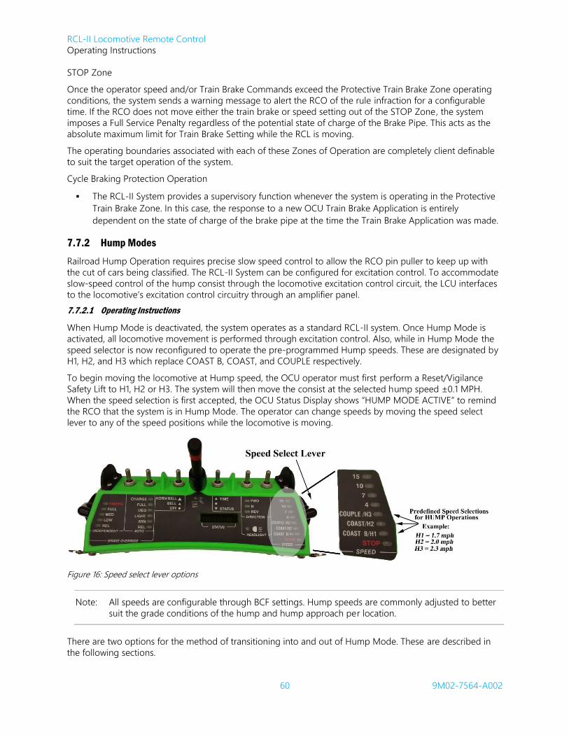
RCL-II Locomotive Remote Control
Operating Instructions
60 9M02-7564-A002
STOP Zone
Once the operator speed and/or Train Brake Commands exceed the Protective Train Brake Zone operating
conditions, the system sends a warning message to alert the RCO of the rule infraction for a configurable
time. If the RCO does not move either the train brake or speed setting out of the STOP Zone, the system
imposes a Full Service Penalty regardless of the potential state of charge of the Brake Pipe. This acts as the
absolute maximum limit for Train Brake Setting while the RCL is moving.
The operating boundaries associated with each of these Zones of Operation are completely client definable
to suit the target operation of the system.
Cycle Braking Protection Operation
The RCL-II System provides a supervisory function whenever the system is operating in the Protective
Train Brake Zone. In this case, the response to a new OCU Train Brake Application is entirely
dependent on the state of charge of the brake pipe at the time the Train Brake Application was made.
7.7.2 Hump Modes
Railroad Hump Operation requires precise slow speed control to allow the RCO pin puller to keep up with
the cut of cars being classified. The RCL-II System can be configured for excitation control. To accommodate
slow-speed control of the hump consist through the locomotive excitation control circuit, the LCU interfaces
to the locomotive’s excitation control circuitry through an amplifier panel.
7.7.2.1 Operating Instructions
When Hump Mode is deactivated, the system operates as a standard RCL-II system. Once Hump Mode is
activated, all locomotive movement is performed through excitation control. Also, while in Hump Mode the
speed selector is now reconfigured to operate the pre-programmed Hump speeds. These are designated by
H1, H2, and H3 which replace COAST B, COAST, and COUPLE respectively.
To begin moving the locomotive at Hump speed, the OCU operator must first perform a Reset/Vigilance
Safety Lift to H1, H2 or H3. The system will then move the consist at the selected hump speed ±0.1 MPH.
When the speed selection is first accepted, the OCU Status Display shows “HUMP MODE ACTIVE” to remind
the RCO that the system is in Hump Mode. The operator can change speeds by moving the speed select
lever to any of the speed positions while the locomotive is moving.
Figure 16: Speed select lever options
Note: All speeds are configurable through BCF settings. Hump speeds are commonly adjusted to better
suit the grade conditions of the hump and hump approach per location.
There are two options for the method of transitioning into and out of Hump Mode. These are described in
the following sections.

RCL-II Locomotive Remote Control
Operating Instructions
61 9M02-7564-A002
7.7.2.2 Entry through OCU
For some operations it is more effective for the RCO to transition into or out of Hump Mode without
boarding the locomotive. To accommodate this, the Hump Mode switch can be located on the OCU. For the
A010* model OCUs, the hump OCU is a separate model with an additional switch mounted on the front of
the OCU. For OCU-III systems, any OCU can be a hump OCU. At IR Assignment, the OCU receives data from
the LCU indicating whether or not the LCU is configured for Hump Mode based on the LCU BCF. If the OCU
is instructed that the LCU is hump-capable, then the OCU’s membrane button labeled “Hump” sends the
hump bit when activated. Otherwise, this button has no function.
Note: Clients who do not have RCL-II systems enabling Hump Mode entry through the OCU will not
have a hump button on the OCU-III membrane. Instead, this button will be labelled “F2” to
indicate that it is currently an unassigned function button.
The process to enter or exit Hump Mode with this method is:
1. Primary RCO commands STOP.
2. Once locomotive is stationary, Primary RCO activates the Hump button on the OCU.
3. LCU transitions into or out of Hump mode, depending on previous mode.
4. LCU sends notification to the OCU Status Display indicating the new state of Hump Mode.
7.7.2.3 Entry through LCU
For some operations, the RCO will not lose productivity by boarding the locomotive in order to transfer into
or out of Hump Mode. To support this type of operation, the Hump Mode Switch is located on the LCU and
is a selector switch with two settings: one for Hump Mode and one for Flat Yard switching.
The process to enter or exit Hump Mode with this method is:
1. Primary RCO commands STOP.
2. Once locomotive is stationary, Primary RCO changes the Hump Mode switch to the desired
position.
3. LCU transitions into or out of Hump Mode, depending on previous mode.
4. Optionally, the system can be configured to generate a Full Service Penalty at this point.
5. LCU sends notification to the OCU Status Display indicating the new state of Hump Mode.
7.7.2.4 Tower OCU Option
Another option for Hump Mode Operation is to enable a Tower OCU. When this feature is active, a console
OCU is installed in a building, typically the hump tower. When in Hump Mode the Tower OCU acts as the
Secondary operator but has only one function, which is to STOP the locomotive once the pushbutton is
pressed. The Tower OCU communicates to the LCU through an external antenna.
A key switch on the Tower OCU functions as an ON/OFF switch. This switch powers down the unit. There is
also a green LED indicator that is visible on the faceplate. This LED flashes every time the Tower OCU
transmits.
Once in Hump Mode, the software looks for the Tower OCU address instead of the Secondary OCU. The
Secondary OCU address on the LCU changes once the Tower address is determined. A POLL – OFFLINE
message is displayed on the Primary OCU until the Tower OCU is detected. The Secondary operator must be
switched to OFF after the Primary activates Hump Mode. The primary OCU Status Display then indicates
“Hump Mode Active” and the Hump speeds will be H1, H2, and H3. The green LED on the Tower OCU now
flashes every second.
If the operator wants to quit using Hump Mode, switch the Secondary OCU to ON. The primary operator
then presses the HUMP Switch once. The message “Hump Mode Cancelled” displays on the OCU and normal
two-person operation can continue.

RCL-II Locomotive Remote Control
Operating Instructions
62 9M02-7564-A002
7.7.2.5 Selecting the Tower OCU Manually
On systems with the Tower OCU feature, the LCU must know the address of the Tower OCU. A table of
addresses can be stored in RCL-II through MainTerm. The selection inside this table can be made through
MainTerm or later manually changed by name with the following process:
1. Press and hold the YES/ALARM RESET button for greater than 2 seconds (or a three-second count),
release the button for greater than 2 seconds (another three-second count), and repeat this cycle
a total of three times.
2. The LCU status display indicates “SEL FREQ/TIMESLOT, PRESS YES OR NO”. Press the
NO/FUNCTION pushbutton to bypass Frequency/Timeslot selection and go immediately to Tower
OCU selection. Alternatively, pressing the YES/ALARM RESET pushbutton will go through the
Frequency/Timeslot procedure; on completion of Frequency/Timeslot selection the operator is
presented with the following display.
3. The LCU status display will indicate “SEL TOWER ADDRESS?”, “PRESS YES OR NO”.
4. Press the YES/ALARM RESET pushbutton.
5. The operator is prompted with the message [“CITY OR YARD NAME ADDRESS”, “PRESS YES TO
ACCEPT OR” “ PRESS NO TO CONTINUE”] (i.e. [“LOUISVILLE 01E1”, “PRESS YES TO ACCEPT OR”
“ PRESS NO TO CONTINUE”], where the bottom line display alternates between the YES and NO
message every 2 seconds).
6. Press the NO/FUNCTION pushbutton to scroll through the list of configured Tower OCU addresses.
7. Press the YES/ALARM RESET pushbutton to lock the system on the displayed Tower OCU. The
Menu will exit.
8. If no pushbutton is pressed for 30 seconds, the status display shows “TOWER OCU
SELECTION”,”TIMED OUT” for 5 seconds and exits; the Tower OCU selection remains at the setting
prior to entering the menu.
7.7.2.6 Automatic Tower OCU Detection
As an optional improvement to ease the maintenance of the Tower OCU table when moving locomotives
between locations, Automatic Tower OCU detection can be added. With this feature, a file that contains GPS
coordinates detailing geographic zones is loaded to RCL-II via MainTerm. Certain zones indicate that the
locomotive is located in a Tower OCU zone and which Tower OCU Address it should use from the Tower
OCU Table when it is set into Hump Mode.
7.7.2.7 Dismissing the Tower OCU
Maintaining continuous operation of the hump is very important. To prevent productivity losses in the event
of a failure of the Tower OCU, a feature exists that permits the Primary OCU to dismiss the Tower OCU. If the
Primary operator determines that the Tower OCU has failed and should be dismissed. the dismissal
procedure is as follows:
1. Primary OCU is turned Off for 30 seconds.
2. LCU dismisses the Tower OCU.
3. Primary OCU is turned back on.
4. LCU permits hump operation without Tower OCU communication.
5. LCU sends message to decoder display and OCU Status Display indicating that the system is
operating in Hump Mode without Tower OCU.
6. To reacquire the Tower OCU the Primary operator must exit Hump Mode and reenter Hump Mode.
RCL-II Locomotive Remote Control
Operating Instructions
63 9M02-7564-A002
7.7.2.8 Quantum HESC Interface
If the RCL-II system will be working in a hump yard that is equipped with a ProYard system that has an
existing interface to Quantum HESC, then the RCL-II system can be configured to work with the HESC
system. With this option, the LCU has a serial link to the locomotive HESC equipment. When the hump tower
sends the requested speed to the HESC hardware, this data forwards to RCL-II. When the RCO selects H1, the
throttle, excitation, and brake values that RCL-II uses are retrieved from the HESC data. With this interface,
the existing ProYard system can be used when in RCL mode to improve the efficiency of the hump operation.
Note that the RCO can override the HESC requested speed by going to a speed other than H1, which will
work as they would in Hump Mode without HESC interface. The RCO can always stop the movement that
HESC is requesting by moving the speed selector to Stop.
7.7.2.9 Dynamic Brake Hump Operation
Some hump operations have a downgrade approach to the crest of the hump. In a hump yard like this, the
locomotives use Dynamic Brake to modulate the speed of the cut as it approaches the hump. RCL-II systems
can accommodate this type of operation in Remote Mode. Note that each dynamic brake hump is different
and should be handled as such. This option requires an Engineering investigation for each location to assess
the track geometry and fine-tune the Dynamic Brake algorithm.
7.7.3 Electronic Handbrake
If the locomotive is equipped with an electronic handbrake, then the RCL-II system can be configured to
interface with this equipment so that the RCO can check or change the status of the handbrake from the
OCU. With additional options, the RCO can verify the effectiveness of the handbrake manually or prompt the
system to do it automatically. 7.7.3.1 General Operation
When equipped, the access to the electronic is through the OCU. The RCO simply toggles through the Status
Display options on the OCU until Handbrake Status is shown. At this point, the system is reporting the
current state of the handbrake, i.e. RELEASED or APPLIED. If the RCO decides to toggle the status of the
handbrake, they activate both Reset/Vigilance switches simultaneously for five seconds. The system then
toggles the handbrake status and reports the status to the OCU.
There are some interlocks and safety verifications associated with the Electronic Handbrake feature. For
example, if a command to set or apply the handbrake does not result in positive feedback that the command
was a success, the system imposes a Full Service Penalty. Additionally, if the system has confirmed that the
handbrake was successfully applied but then detects that the locomotive begins moving, it imposes a Full
Service Penalty.
7.7.3.2 Manual Handbrake Verification
With the general operation of the electronic handbrake interface, commanding a speed is not permitted
when the handbrake is set. This is intended to prevent excessive wear to the handbrake, and to serve as a
reminder to the RCO that the handbrake is still set.
In order to permit the RCO to test the effectiveness of the handbrake, a handbrake test mode can be
configured through BCF. With this feature, the RCO can command a limited movement with the handbrake
set. The maximum throttle notch and maximum time that the attempted movement can occur are
configurable. This feature is intended to be used as follows:
1. RCO prompts LCU to set the handbrake.
2. LCU sets handbrake, and confirms that it applied and notifies RCO.
3. RCO commands a movement.
4. LCU starts movement under the restrictions of throttle notch and duration configured in BCF.
5. RCO verifies that locomotive loaded during the brief throttle activation and did not move in excess
of the client RR operating rules for handbrake effectiveness verification.

RCL-II Locomotive Remote Control
Operating Instructions
64 9M02-7564-A002
7.7.3.3 Automated Handbrake Verification
The manual handbrake verification feature requires that the locomotive is occupied at the time of the test.
The RCL-II system can be configured to automate this test. With the Automated Handbrake Verification, the
system operates as follows:
1. RCO prompts LCU to set the handbrake.
2. LCU sets handbrake, and confirms that it applied and notifies RCO.
a. LCU notification to RCO includes a prompt to verify the effectiveness.
3. RCO commands a restricted movement to test the handbrake.
4. LCU starts movement under the restrictions of throttle notch and duration configured in BCF, but
also monitors the system speed, traction motor current, and odometer.
5. LCU applies tractive effort until it detects that the locomotive loads, then cuts tractive effort.
a. If the LCU detects that locomotive movement was at an acceptable level, it reports to the
RCO that the handbrake has been verified as effective.
b. If the LCU detects that the was not at an acceptable level it reports to the RCO that the
handbrake has been verified as ineffective and imposes an Emergency Brake Penalty.
7.7.4 EPD/PSP
In locations where a Remote Control Zone can be established and maintained, it is possible for the RCO to
initiate a movement where the point is not protected by a person. The EPD or PSP system gradually slows
movement to a stop before reaching a predefined point.
7.7.4.1 Concept of Operation
The EPD and PSP systems were developed separately to provide similar solutions. Both systems utilize track-
mounted transponders and GPS Zones. The systems have slight differences in operation. In some instances
one model will suit your operation better than the other. Consult your Sales representative for details.
7.7.4.2 Crossing Zone Protection
As a feature of EPD and PSP is Crossing Zone Protection. This feature uses transponders and zones to
automatically sound the horn and bell at grade crossings. Consult your Sales representative for details.
7.7.5 Fast Idle Charge
This optional feature allows the RCO to fast idle the locomotive to increase the rate at which the air
compressor can generate air. If this feature is enabled, any time the RCL is in Neutral the Primary Operator
can fast idle the engine by activating a Reset/Vigilance switch and then moving the Speed Select Lever out of
STOP. In this mode, the speed selections are throttle settings with a max throttle point of notch 5.
7.7.6 Kick Feature
When this feature is enabled, a lift to the maximum speed set point causes the system to reach notch 8
within two seconds. The speed set point is the same, but the system reaches maximum throttle faster to aid
in kicking operations.
7.7.7 Man Down Test Option
Laird highly recommends that the Man Down synthesized voice transmissions are tested during the start of
shift tests. In an attempt to help enforce this practice, RCL-II can be configured to require that the Man Down
test is completed after the completion of an IR Assignment session. If this feature is active, the system
prompts the RCO(s) to complete the Man Down test before Emergency Recovery is permitted. To complete
the test, the RCO(s) only need to tilt the OCU(s) until the Tilt Warning Timer expires and triggers the
transmission of the Man Down message.
RCL-II Locomotive Remote Control
Operating Instructions
65 9M02-7564-A002
7.7.8 OCU Assignment Retention
There are multiple methods to manually clear the OCU or LCU stored data regarding Assignment. Separate
from the manual methods for clearing Assignment, RCL-II has two options for retaining the assignment data.
With one method, the system retains OCU Assignment indefinitely until manually cleared or a new
Assignment Session occurs. The other option for Assignment Retention is based on time in Manual Mode or
Off. With this option, a client-defined timer is configured in the system BCF. On entry to Remote Mode, the
system checks the time that it was set into Manual Mode (or shut off). If the time between mode changes
exceeds the time configured in the BCF, the system clears the OCU addresses from the previous OCU
Assignment and will not be capable of operating in Remote Mode until a successful OCU Assignment occurs.
7.7.9 Operator Emergency Horn/Bell
This feature automatically activates the bell, horn, or both when either operator commands an Emergency
Brake Application with the Independent Brake Override while the locomotive is moving. The automatic
activation of either or both sounding device ends when the locomotive reaches a complete stop.
7.7.10 Slug Monitoring
This feature provides the RCO with an indication of the status of a mated slug on the OCU Status Display.
The indication is whether the slug is online or offline.
7.7.11 Tilt Time Extend Options
7.7.11.1 50 Second Timer Method
In order for the Tilt Extend request to be accepted:
- OCU must not be tilted.
- Locomotive must be stopped (for PRI only).
- Speed lever must be set to STOP (for PRI only).
- Pitch cannot be in progress.
Tilt Extend is cancelled if:
- PRI changes switch selection.
Tilt Extend lasts for 50 seconds then starts a 5 second countdown on OCU.
Tilt Extend cannot be selected if already in a Tilt Extend, i.e. no reloading Tilt Extends.
7.7.11.2 9 Second Timer Method
In order for the tilt extend request to be accepted:
- OCU must not be tilted.
- Locomotive must be stopped.
- Speed lever must be set to STOP (for PRI only).
- Pitch cannot be in progress.
Tilt extend is cancelled if a pitch is commanded.
Both OCUs are in A Tilt Extend condition when either Tilt Extends.
Tilt extend timer is 9 seconds.
RCO can request another Tilt Extend while in Tilt Extend mode i.e. reloading Tilt Extends.
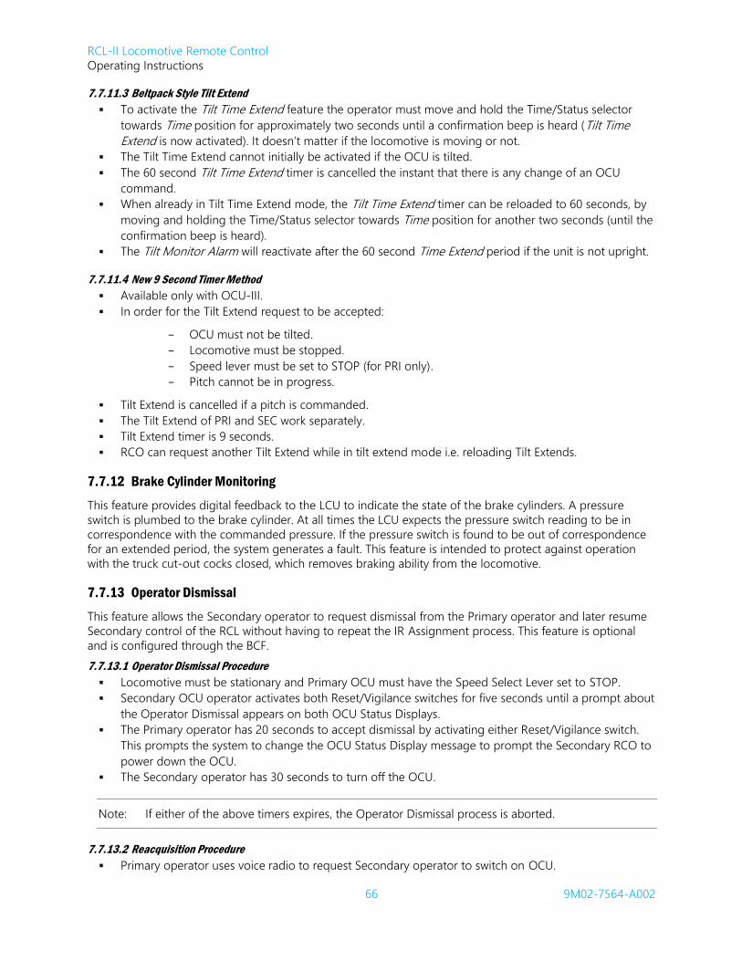
RCL-II Locomotive Remote Control
Operating Instructions
66 9M02-7564-A002
7.7.11.3 Beltpack Style Tilt Extend
To activate the Tilt Time Extend feature the operator must move and hold the Time/Status selector
towards Time position for approximately two seconds until a confirmation beep is heard (Tilt Time
Extend is now activated). It doesn’t matter if the locomotive is moving or not.
The Tilt Time Extend cannot initially be activated if the OCU is tilted.
The 60 second Tilt Time Extend timer is cancelled the instant that there is any change of an OCU
command.
When already in Tilt Time Extend mode, the Tilt Time Extend timer can be reloaded to 60 seconds, by
moving and holding the Time/Status selector towards Time position for another two seconds (until the
confirmation beep is heard).
The Tilt Monitor Alarm will reactivate after the 60 second Time Extend period if the unit is not upright.
7.7.11.4 New 9 Second Timer Method
Available only with OCU-III.
In order for the Tilt Extend request to be accepted:
- OCU must not be tilted.
- Locomotive must be stopped.
- Speed lever must be set to STOP (for PRI only).
- Pitch cannot be in progress.
Tilt Extend is cancelled if a pitch is commanded.
The Tilt Extend of PRI and SEC work separately.
Tilt Extend timer is 9 seconds.
RCO can request another Tilt Extend while in tilt extend mode i.e. reloading Tilt Extends.
7.7.12 Brake Cylinder Monitoring
This feature provides digital feedback to the LCU to indicate the state of the brake cylinders. A pressure
switch is plumbed to the brake cylinder. At all times the LCU expects the pressure switch reading to be in
correspondence with the commanded pressure. If the pressure switch is found to be out of correspondence
for an extended period, the system generates a fault. This feature is intended to protect against operation
with the truck cut-out cocks closed, which removes braking ability from the locomotive.
7.7.13 Operator Dismissal
This feature allows the Secondary operator to request dismissal from the Primary operator and later resume
Secondary control of the RCL without having to repeat the IR Assignment process. This feature is optional
and is configured through the BCF.
7.7.13.1 Operator Dismissal Procedure
Locomotive must be stationary and Primary OCU must have the Speed Select Lever set to STOP.
Secondary OCU operator activates both Reset/Vigilance switches for five seconds until a prompt about
the Operator Dismissal appears on both OCU Status Displays.
The Primary operator has 20 seconds to accept dismissal by activating either Reset/Vigilance switch.
This prompts the system to change the OCU Status Display message to prompt the Secondary RCO to
power down the OCU.
The Secondary operator has 30 seconds to turn off the OCU.
Note: If either of the above timers expires, the Operator Dismissal process is aborted.
7.7.13.2 Reacquisition Procedure
Primary operator uses voice radio to request Secondary operator to switch on OCU.
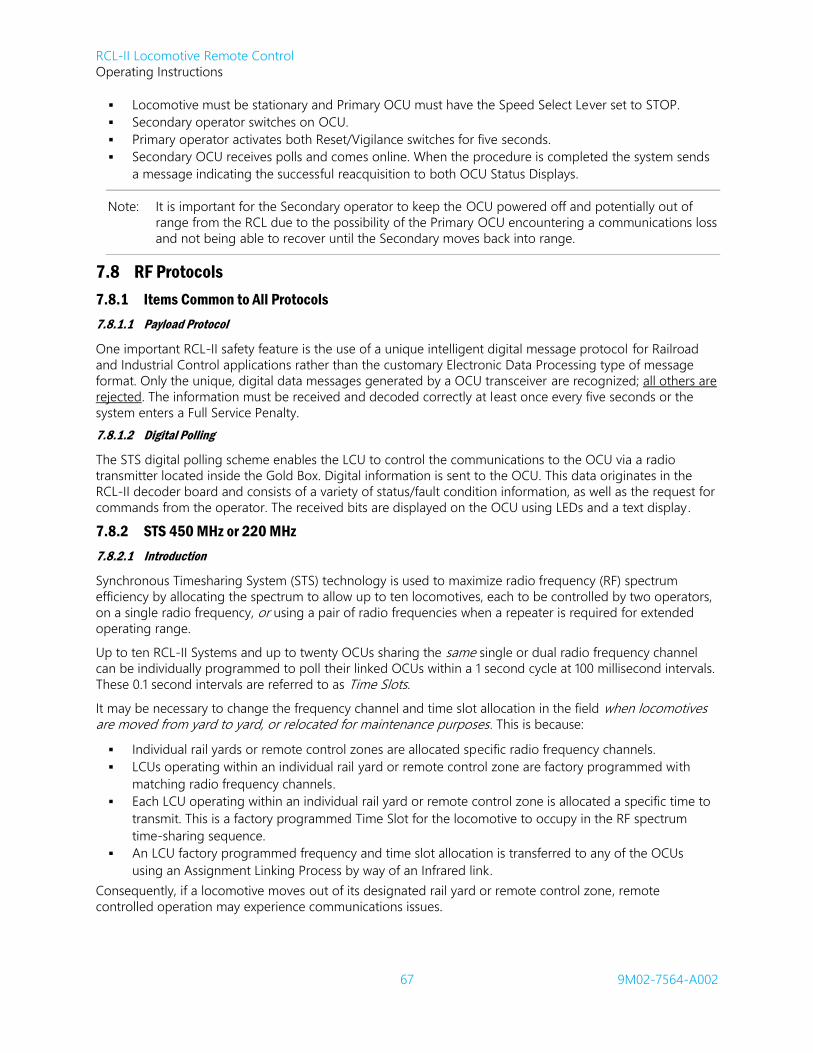
RCL-II Locomotive Remote Control
Operating Instructions
67 9M02-7564-A002
Locomotive must be stationary and Primary OCU must have the Speed Select Lever set to STOP.
Secondary operator switches on OCU.
Primary operator activates both Reset/Vigilance switches for five seconds.
Secondary OCU receives polls and comes online. When the procedure is completed the system sends
a message indicating the successful reacquisition to both OCU Status Displays.
Note: It is important for the Secondary operator to keep the OCU powered off and potentially out of
range from the RCL due to the possibility of the Primary OCU encountering a communications loss
and not being able to recover until the Secondary moves back into range.
7.8 RF Protocols
7.8.1 Items Common to All Protocols
7.8.1.1 Payload Protocol
One important RCL-II safety feature is the use of a unique intelligent digital message protocol for Railroad
and Industrial Control applications rather than the customary Electronic Data Processing type of message
format. Only the unique, digital data messages generated by a OCU transceiver are recognized; all others are
rejected. The information must be received and decoded correctly at least once every five seconds or the
system enters a Full Service Penalty.
7.8.1.2 Digital Polling
The STS digital polling scheme enables the LCU to control the communications to the OCU via a radio
transmitter located inside the Gold Box. Digital information is sent to the OCU. This data originates in the
RCL-II decoder board and consists of a variety of status/fault condition information, as well as the request for
commands from the operator. The received bits are displayed on the OCU using LEDs and a text display.
7.8.2 STS 450 MHz or 220 MHz
7.8.2.1 Introduction
Synchronous Timesharing System (STS) technology is used to maximize radio frequency (RF) spectrum
efficiency by allocating the spectrum to allow up to ten locomotives, each to be controlled by two operators,
on a single radio frequency, or using a pair of radio frequencies when a repeater is required for extended
operating range.
Up to ten RCL-II Systems and up to twenty OCUs sharing the same single or dual radio frequency channel
can be individually programmed to poll their linked OCUs within a 1 second cycle at 100 millisecond intervals.
These 0.1 second intervals are referred to as Time Slots.
It may be necessary to change the frequency channel and time slot allocation in the field when locomotives are moved from yard to yard, or relocated for maintenance purposes. This is because:
Individual rail yards or remote control zones are allocated specific radio frequency channels.
LCUs operating within an individual rail yard or remote control zone are factory programmed with
matching radio frequency channels.
Each LCU operating within an individual rail yard or remote control zone is allocated a specific time to
transmit. This is a factory programmed Time Slot for the locomotive to occupy in the RF spectrum
time-sharing sequence.
An LCU factory programmed frequency and time slot allocation is transferred to any of the OCUs
using an Assignment Linking Process by way of an Infrared link.
Consequently, if a locomotive moves out of its designated rail yard or remote control zone, remote
controlled operation may experience communications issues.

RCL-II Locomotive Remote Control
Operating Instructions
68 9M02-7564-A002
7.8.2.2 User Field Programming
Typically, the frequency and timeslot will be changed through the Maintenance Terminal. This can be done
with a direct serial connection or through the cellular modem interface. If the user is unable to connect with
the Terminal, an alternative method of changing the frequency timeslot is available.
Notes: Laird recommends that you maintain up-to-date records of individual frequency and timeslot
allocations for all LCUs at your individual rail yards and/or remote control zones, including new
frequency and timeslot allocations made by yourselves.
When field programming frequencies and timeslots into your LCUs, ensure that no other LCU have
the same frequency or timeslot.
Duplicating frequencies and timeslots may result in unexpected communications losses that will
shut down the affected locomotive(s).
This procedure allows an authorized person to switch from one pre-programmed frequency channel to
another, and similarly select the time slot for the locomotive to occupy in the RF spectrum time-sharing
sequence. The channels and time slot are changed using the existing Function Pushbuttons located on the
front of the LCU or Remote Display while observing prompts on the display. This procedure is only possible
when the LCU is in Remote Mode and is not in communication with any OCUs.
The procedure is as follows:
1. Press and hold the YES/ALARM RESET button for greater than two seconds (or a three-second
count), release the button for greater than two seconds (another three-second count), and repeat
this cycle a total of three times.
2. The LCU status display indicates “SEL FREQ/TIMESLOT, PRESS YES OR NO”. Press the YES/ALARM
RESET pushbutton to select the frequency/timeslot.
3. The LCU status display indicates: “SELECT RF CHANNEL 1L” and the second line of the display
alternates the following messages: “PRESS YES TO ACCEPT OR”, “PRESS NO TO CONTINUE”.
4. Press the NO/FUNCTION pushbutton to increment from 1 through 30 channel numbers.
5. Stop incrementing at the desired channel number (e.g. 1H).
6. Press the YES/ALARM RESET pushbutton to lock the system on the channel number displayed.
7. Once a Channel is selected, the status display changes to indicate “SELECT TIME SLOT 1” and the
second line of the display alternates the following messages: “PRESS YES TO ACCEPT OR”, “PRESS
NO TO CONTINUE”.
8. Press the NO/FUNCTION pushbutton to increment from 1 through 10 time slots.
9. Stop incrementing at the desired Time Slot.
10. Press the YES/ALARM RESET pushbutton to lock the system on that Time Slot.
11. Channel & Time Slot selection is now complete – the Status Display will show your Channel & Time
Slot selection and ask if this is correct.
12. Press YES/ALARM RESET pushbutton to finish, NO/FUNCTION pushbutton to start over.
Note: OCUs must be re-assigned by the LCU after a frequency or timeslot change.
7.8.3 STSII 220 MHz
Synchronous Timesharing System (STS) technology is used to enable a frequency and timeslot to be
automatically selected when linking an OCU to the LCU. This STS II option does away with the need to
manually program frequencies and time slots into your LCU.
The STS II option is designed around our standard STS™ protocol. However the automatic time slotting
system is not based on fixed time slots. Instead, it randomly picks a frequency and time slot, as well as being
capable of automatically selecting unused timeslots in the event of interference or channel occupation.
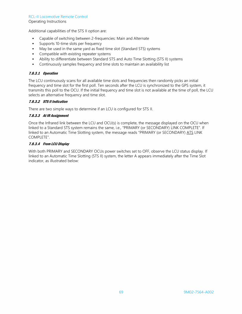
RCL-II Locomotive Remote Control
Operating Instructions
69 9M02-7564-A002
Additional capabilities of the STS II option are:
Capable of switching between 2-frequencies: Main and Alternate
Supports 10-time slots per frequency
May be used in the same yard as fixed time slot (Standard STS) systems
Compatible with existing repeater systems
Ability to differentiate between Standard STS and Auto Time Slotting (STS II) systems
Continuously samples frequency and time slots to maintain an availability list
7.8.3.1 Operation
The LCU continuously scans for all available time slots and frequencies then randomly picks an initial
frequency and time slot for the first poll. Ten seconds after the LCU is synchronized to the GPS system, it
transmits this poll to the OCU. If the initial frequency and time slot is not available at the time of poll, the LCU
selects an alternative frequency and time slot.
7.8.3.2 STS II Indication
There are two simple ways to determine if an LCU is configured for STS II.
7.8.3.3 At IR Assignment
Once the Infrared link between the LCU and OCU(s) is complete, the message displayed on the OCU when
linked to a Standard STS system remains the same, i.e., “PRIMARY (or SECONDARY) LINK COMPLETE”. If
linked to an Automatic Time Slotting system, the message reads “PRIMARY (or SECONDARY) ATS LINK
COMPLETE”.
7.8.3.4 From LCU Display
With both PRIMARY and SECONDARY OCUs power switches set to OFF, observe the LCU status display. If
linked to an Automatic Time Slotting (STS II) system, the letter A appears immediately after the Time Slot
indicator, as illustrated below:

RCL-II Locomotive Remote Control
Operating Instructions
70 9M02-7564-A002
\ OFF D 452.53750- 01 R0
/ OFF D 452.53750- 04A R0
A 4 p 1F1A B 3 s 1F19 LOCO_ID#
A 4 p 1F1A B 3 s 1F19 LOCO_ID#
TIMESLOT
TIMESLOT
TM
TM
FREQUENCY
Standard STS System Status Display
STS II System Status Display
FREQUENCY AUTOMATIC
Figure 17: Example LCU System Status Displays
7.8.4 Common Air Interface 220 MHz
The RCL-II system is also capable of maintaining RF communications in accordance with the AAR Standard S-
9153: Common Air Interface (CAI-12) Communications for Remote Control Locomotive Systems (RCL)
Operating at 220 MHz. In this case, portions of our proprietary protocol are maintained. The messages that
would normally be sent in our RF message are encapsulated inside the CAI-12 formatted message to
maintain the integrity and security of our communications over the common network.
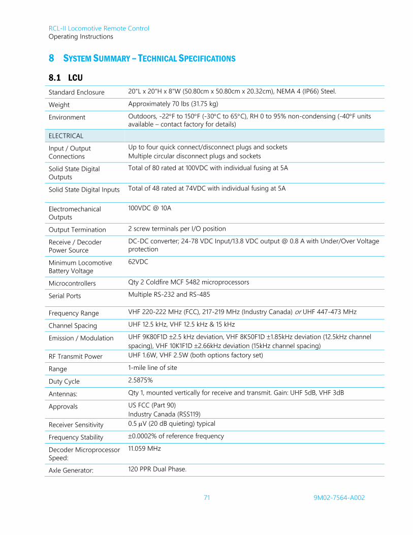
RCL-II Locomotive Remote Control
Operating Instructions
71 9M02-7564-A002
8 SYSTEM SUMMARY – TECHNICAL SPECIFICATIONS
8.1 LCU
Standard Enclosure 20"L x 20"H x 8"W (50.80cm x 50.80cm x 20.32cm), NEMA 4 (IP66) Steel.
Weight Approximately 70 lbs (31.75 kg)
Environment Outdoors, -22F to 150F (-30C to 65C), RH 0 to 95% non-condensing (-40F units
available – contact factory for details)
ELECTRICAL
Input / Output
Connections
Up to four quick connect/disconnect plugs and sockets
Multiple circular disconnect plugs and sockets
Solid State Digital
Outputs
Total of 80 rated at 100VDC with individual fusing at 5A
Solid State Digital Inputs Total of 48 rated at 74VDC with individual fusing at 5A
Electromechanical
Outputs
100VDC @ 10A
Output Termination 2 screw terminals per I/O position
Receive / Decoder
Power Source
DC-DC converter; 24-78 VDC Input/13.8 VDC output @ 0.8 A with Under/Over Voltage
protection
Minimum Locomotive
Battery Voltage
62VDC
Microcontrollers Qty 2 Coldfire MCF 5482 microprocessors
Serial Ports Multiple RS-232 and RS-485
Frequency Range VHF 220-222 MHz (FCC), 217-219 MHz (Industry Canada) or UHF 447-473 MHz
Channel Spacing UHF 12.5 kHz, VHF 12.5 kHz & 15 kHz
Emission / Modulation UHF 9K80F1D 2.5 kHz deviation, VHF 8K50F1D 1.85kHz deviation (12.5kHz channel
spacing), VHF 10K1F1D 2.66kHz deviation (15kHz channel spacing)
RF Transmit Power UHF 1.6W, VHF 2.5W (both options factory set)
Range 1-mile line of site
Duty Cycle 2.5875%
Antennas: Qty 1, mounted vertically for receive and transmit. Gain: UHF 5dB, VHF 3dB
Approvals US FCC (Part 90)
Industry Canada (RSS119)
Receiver Sensitivity 0.5 V (20 dB quieting) typical
Frequency Stability 0.0002% of reference frequency
Decoder Microprocessor
Speed:
11.059 MHz
Axle Generator: 120 PPR Dual Phase.

RCL-II Locomotive Remote Control
Operating Instructions
72 9M02-7564-A002
8.2 EPI
Standard Enclosure 30"L x 24"H x 10"W (76.2cm x 61cm x 25.4cm), NEMA 4 (IP66) Steel
Weight Approximately 120 lbs (54.43 kg)
Environment Outdoors, -22F to 150F (-30C to 65C), RH 0 to 95% non-
condensing )
Electro-mechanical Relay Outputs Qty 1, 100VDC @ 10A
Electrical Input / Output
Connections
Qty 3, quick connect/disconnect plugs and sockets
Pneumatic Input / Output
Connections
1/2" & 1" NPT connectors
8.3 LJB
Enclosure 20"L x 20"H x 10"W (50.8cm x 50.8cm x 25.4cm), NEMA 4 (IP66) Steel.
Weight Approximately 45 lbs (20.41 kg)
Environment Outdoors, -22F to 150F (-30C to 65C), RH 0 to 95% non-condensing Electro-
mechanical Relay
Outputs Qty 5, 100VDC @ 10A
Electrical
Input/Output
Connections
Screw Terminal Block – 90 input/output screw terminals
8.4 Remote Display
Enclosure 2” x 5.5” x 9” Cast Aluminium
Weight Approximately 2.8 lbs (1.27 kg)
Environment Outdoors, -40F to 158F (-40C to 70C),
RH 0 to 95% non-condensing
8.5 OCU (A010* Model)
Case Material Cast Magnesium with high strength power-coat finish
Environment Outdoors, -22º F to 122º F (-30º C to 50º C)
RH 0 to 95% no-condensing
Watertight NEMA 35 (IP65) (heavy rain, dust, oil resistant)
Weight Approximately 4.5 lbs (2 kg) including battery
Size Approximately 10” L x 3.5” W x 4.5” H (25.4 cm x 8.89 cm x 11.43 cm)
Battery Industry standard 7.2 VDC Rechargeable Nickel Metal Hydride (Ni-MH) Battery Pack
mounted externally to bottom of OCU
Battery Life Ni-MH – approximately 12 hours continuous operation
Antenna Externally mounted stubby whip antenna for optimum signal transmission
Frequency Range VHF 220-222 MHz (FCC) 217-219 MHz (Industry Canada) or UHF 447-473 MHz
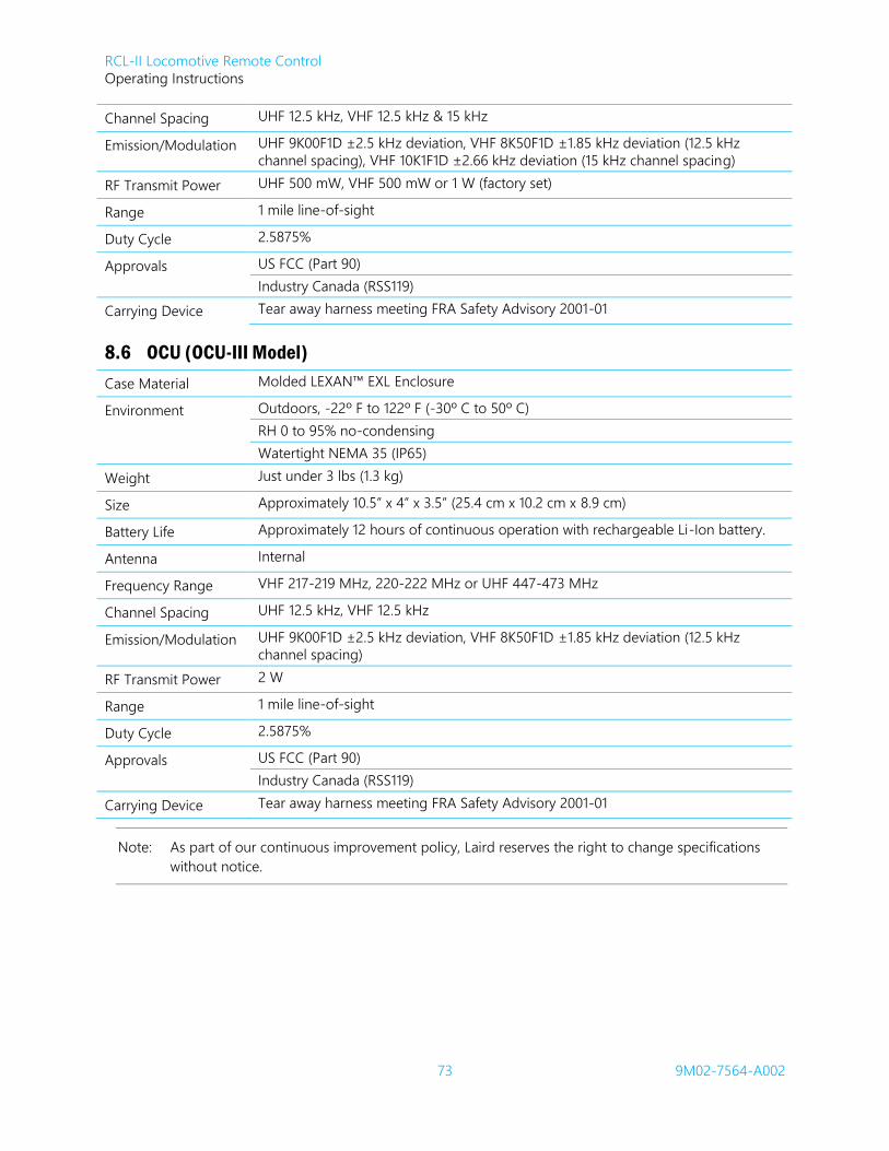
RCL-II Locomotive Remote Control
Operating Instructions
73 9M02-7564-A002
Channel Spacing UHF 12.5 kHz, VHF 12.5 kHz & 15 kHz
Emission/Modulation UHF 9K00F1D ±2.5 kHz deviation, VHF 8K50F1D ±1.85 kHz deviation (12.5 kHz
channel spacing), VHF 10K1F1D ±2.66 kHz deviation (15 kHz channel spacing)
RF Transmit Power UHF 500 mW, VHF 500 mW or 1 W (factory set)
Range 1 mile line-of-sight
Duty Cycle 2.5875%
Approvals US FCC (Part 90)
Industry Canada (RSS119)
Carrying Device Tear away harness meeting FRA Safety Advisory 2001-01
8.6 OCU (OCU-III Model)
Case Material Molded LEXAN™ EXL Enclosure
Environment Outdoors, -22º F to 122º F (-30º C to 50º C)
RH 0 to 95% no-condensing
Watertight NEMA 35 (IP65)
Weight Just under 3 lbs (1.3 kg)
Size Approximately 10.5” x 4” x 3.5” (25.4 cm x 10.2 cm x 8.9 cm)
Battery Life Approximately 12 hours of continuous operation with rechargeable Li-Ion battery.
Antenna Internal
Frequency Range VHF 217-219 MHz, 220-222 MHz or UHF 447-473 MHz
Channel Spacing UHF 12.5 kHz, VHF 12.5 kHz
Emission/Modulation UHF 9K00F1D ±2.5 kHz deviation, VHF 8K50F1D ±1.85 kHz deviation (12.5 kHz
channel spacing)
RF Transmit Power 2 W
Range 1 mile line-of-sight
Duty Cycle 2.5875%
Approvals US FCC (Part 90)
Industry Canada (RSS119)
Carrying Device Tear away harness meeting FRA Safety Advisory 2001-01
Note: As part of our continuous improvement policy, Laird reserves the right to change specifications
without notice.

RCL-II Locomotive Remote Control
Operating Instructions
74 9M02-7564-A002
APPENDIX I: OCU-III SERVICEABILITY
The OCU-III is specifically designed to meet the needs of the robust environmental conditions found in rail
yards.
The complex integrated design methodology used to develop the OCU-III allows Laird to develop a solution
with a lower weight, cohesive software/hardware features, and a leading edge internally-housed antenna
solution.
The ongoing service of this device is provided through Laird trained service technicians. The OCU-III housing
may not be opened by the customer. If the D-Rings on the outside of the housing need to be replaced, the
Model Numbers below provide the customer with the parts needed.
CAUTION:
The D-Rings, on the outside of the housing, are designed to allow customers to replace them if needed. For replacement of the D-Rings, Loctite 425™ may be used per the instructions provided with Kit Numbers: K2002, K2003, and K2004. No other adhesives are approved for use by Laird. Laird is not responsible for damage to devices caused by the use of any other adhesives.
Model Number Description
Kits
K2002 Qty 4: Upper D-Ring with Screws
K2003 Qty 4: Lower D-Ring with Screws
K2004 Qty 10: OCU-III D-Ring Screws
Single Piece Parts
2DRG-8500-A001-A Upper D-ring assembly
2DRG-8500-A101-A Lower D-ring assembly
Batteries
1BAT-8437-A001 Rechargeable Li-Ion
Chargers
1PRT-8449-A001 Single Bay Unit , for OCU-III Li-Ion Only
1PRT-8451-A001 Six Bay Unit for OCU-III Li-Ion Only

RCL-II Locomotive Remote Control
Operating Instructions
75 9M02-7564-A002
LAIRD WIRELESS AUTOMATION & CONTROL SOLUTIONS, SUPPORT FACILITIES
NAME PHONE FAX CONTACT
USA
Laird Controls North America Inc.
655 N River Rd NW Ste A
Warren, OH 44483
+1.234.806.0018 +1.234.806.0019 Systems-US-
CANADA
Laird Controls Canada LTD
Montreal
3850 Griffith Ave.
St. Laurent PQ H4T 1A7
Canada
+1.514.908.1659 +1.514.908.1673 Systems-CDN-
BRAZIL
Cattron-Theimeg Americas Ltda.
Rua Antonio Rodrigues De Carvalho,
435
13033-610 Campinas – SP- Brazil
+55.19.3243.7803 +55.19.3243.9258 Systems-BR-
UNITED KINGDOM
Cattron-Theimeg UK Ltd
Riverdene Business Park Unit J
Molesey Road Hersham
Walton-on-Thames Surrey KT12 4RG
+44.1.932.247511 +44.1.932.220937 Systems-UK-
SOUTH AFRICA
Cattron-Theimeg Africa (Pty) Ltd.
24 O’Rielly Merry Rd
Rynfield, Benoni
Gauteng 1518, South Africa
+27.11.425.1123 +27.11.849.5717 Systems-SA-
CHINA
Cattron Controls Asia-Pacific LTD
Suite 417 Mingguang Business Building
351 Zhaohua Road, Shanghai 200050
China
+86.21.31200188 +86.21.60290498 Systems-CN-
GERMANY
Cattron-Theimeg Europe GmbH & Co.
Krefelder Strasse 423-425
41066 Mönchengladbach
Germany
+49.2161.6363.0 +49.2161.6363.100 Systems-EU-