r&d plan for ilc ild) tpc in 2010 -2012dpp/linear_collider/images/talks... · r&d plan for...
TRANSCRIPT

R&D plan for ILC((((ILD) TPC in 2010 - 2012(LC TPC Collaboration)
LCWA09 Tracker Session02 October 2009
LC TPC CollaborationTakeshi MATSUDA
DESY/FLC
1

l High Momentum resolution: δ(1/pt) ≦≦≦≦ 4 x 10⁻⁵ (TPC alone)
àààà 200 position measurements along each track with the point resolution of σrφ ~ 100µm at 3.5T àààà MPGD TPC
[àààà a several position measurements with σrφ~ 10µm at 5T àààà SiTR ]
l High tracking efficiency down to low momentum for PFAl Minimum material of TPC for PFA : 4%X0 in barrel/15% X0 in endplatel dE/dX : 5%
R&D Goals for ILC (ILD) TPC
2
l dE/dX : 5%
Tracking efficiency w pair background(S. Aplin & F. Gaede)
ttbar overlayedwith 100BX of pairbackgrounds
Preliminary->
> 99%

Analog TPC: Immediate options if the current ILC schedule
(1) Multi layer GEM + Narrow (1mm wide) pad readout: Defocusing by multilayer GEMNarrow (1mm) pads èèèè Larger readout channelsEffective No. of electrons (Neff): ~~~~ 20
(2) MicroMEGAS + Resistive anode pad (2-3mm wide)Widening signal by resistive anode Wider pads èèèè Less readout channels
Options of MPGD for ILC TPCBased on the studies with studies with small small MPGD TPC PrototypesMPGD TPC Prototypes
3
Wider pads èèèè Less readout channelsNeff: ~~~~ 30
Digital TPC:
(3) Ingrid-MicroMEGAS + Timepix:Digital àààà Free from the gas gain fluctuation
More information from primary electrons and Thus better position resolution (to be demonstrated)
(4) Multilayer GEM + Timepix:Need to improve the efficiency for primary electrons

TPC Gas: Gas physicsNo. of primary electronsFluctuation of ionization AttachmentDiffusionDrift velocity Aging
Filed caeg in MagnetE & B fieldDistortions (ExB)Ions
TPC
4
http://www-jlc.kek.jp/subg/cdc/lib/DOC/TPCSchool/200801/Fujii_Keisuke/TPCfundamentals-1.pdf (42MB)
MPGDGas amplification:
MicroMEGAS or GEMGain fluctuationIon backflow
Position measurement:Conductive padResistive anode padsPixels
Low noise electronics:Analog/digital redaout
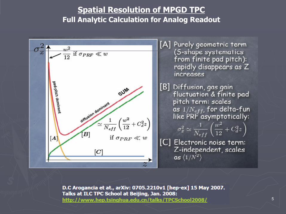
Spatial Resolution of MPGD TPCFull Analytic Calculation for Analog Readout
5

Spatial Resolution of MPGD TPCComparison between different MPGD options
From the full analytic calculation of point resolution of MPGDTPC (*), σ(x) may be parameterized as:
eff
2d2
0xN
zCσσ
⋅+=
Where Neff is the number of effective electrons, and Cd the diffusionconstant of gas. σ(0) is determined by the configuration of MPGDdetector and electronics. This formula itself may be applicableempirically to digital TPC.
(*)
6

Spatial Resolution of MPGD TPC:Neff
M. Kobayashi
K may be dependent of the amplification scheme. If K is small, then Neff can be àààà 35. In the case of GEM, Neff seems to be 20-25.
7

Position ResolutionPosition ResolutionGEM and GEM and MicroMEGASMicroMEGAS
MicroMEGASRMS (avalanche) on pads = 15µm
GEM1mm x 6 mm pads
RMS (avalanche) 350µm
MicroMEGAS needs a resistive anode to widen the signal.
8

Position Resolution: NeffPosition Resolution: NeffCalculation for ILC TPC Calculation for ILC TPC
These calculations are for GEM. The dependence on Neff is similar for MicroMEGAS in large drift distance. 9

Silicon Pixel Readout of Silicon Pixel Readout of MicroMEGASMicroMEGAS TPC:TPC:
l Ingrid MicroMEGAS Timepix: Integrated grid, i.e., MicroMEGAS mesh on the top of the CMOS chip. Now even two layers.
l To prevent discharge (in particular in Ar-based gases) to kill the chip, a discharge protection of high-resistive (~1011) Ω·cm amorphous Si layer (3àààà 20 µm thick) on top of CMOS chip was processed. Now also Si(rich) N protection.
l Good energy resolution of Ingrid devices“Ingrid” + a-Si protection
NIKHEF, Saclay
10
l Good energy resolution of Ingrid devices
l Ion backflow of a few per-mil level at high field ratio.
l Still need higher gain (a few 1,000).
l MicroMEGAS + TimePix can be Digital TPC avoiding the effect of the gain fluctuation, possibly improving the spatial resolution by a few 10 %.
l More R&D needed: silicon trough hole to minimize dead region and 3D chip technology to implement high speed DAQ. 5 cm3 Digital TPC with MicroMEGAS
Two electron tracks from 90Sr source

DIGITAL TPC : Toward Ultimate Resolution
(1) Detect all drift electrons individually along track with microscopic pixel
(2) Measure position of each primary electron digitally with necessaryprecision (50 µm pixels)
àààà No deterioration due to the gas gain fluctuation
(Narrow signal spread of MicroMEGAS ~~~~10 µm is the key.)
11
To beat out the analog MPGD TPC in term of momentum resolution of TPC,need very high detection efficiency of primary electrons:
(a) At the chip level (actually measured to be close to 100%: next slide)
(b) No geometrical dead space in TPC application (continuous measurement along track) requires;(i) Silicon through-hole to route TimePix signal to its backside, and (ii) compact/high speed data readout

Measure electrons from an X-ray conversion and count them and study the fluctuations (Nikhef-Saclay)
àààà Single electron efficiency seemsto be high enough.
DIGITAL TPC : Ultimate ResolutionMicroMEGAS + Timepix
12
Fe55

l From Medipix to Timepix chip in 2006 (CERN): 256x256 pixels of 55x55µm2
with a preamp, a discriminator and a counter to measure drift time.
l Detailed beam test at DESY since 2007. GEM+Timepix sees “bubbles” which show the size of signal spread of GEM and may contain more than one primary electrons.
With a triple GEM
Silicon Pixel Readout of MPGD TPCSilicon Pixel Readout of MPGD TPCGEMGEM
Freiberg & Bonn
Neff = 11With large Cd (ArCo2)
13
primary electrons.
l Detection efficiency of the primary electron, or Neff, is an issue to apply to ILC TPC. (The rapid deterioration of the position resolution as drift distance increases.)
l It is very attractive with its powerful graphic capability though.
Results of DESY beam testriple GEM +Timepix (Freiberg + Bonn)

TPC Large Prototype Beam Test (LP1TPC Large Prototype Beam Test (LP1))
LP1 at DESY T24-1 beam area
Please refer to Klaus Dehmelt’ stalk14

TPC Large TPC Large Prototype Prototype Beam Test at Beam Test at DESY (LP1 Test)DESY (LP1 Test)
GoalsGoals
1.1. Study, in practice, design and fabricationStudy, in practice, design and fabrication ofof all components of all components of MPGD TPC in larger scale; fMPGD TPC in larger scale; fieldield cagecage,, endplateendplate, detector , detector modules,, frontmodules,, front--end electronics and field mapping of non end electronics and field mapping of non uniform magnetic field. (But not yet the engineering stageuniform magnetic field. (But not yet the engineering stage.).)
2.2. Demonstrate Demonstrate fullfull--volume trucking in nonvolume trucking in non--uniform magnetic uniform magnetic field, trying to provide a proof for the momentum resolution field, trying to provide a proof for the momentum resolution at LC TPC. at LC TPC. at LC TPC. at LC TPC.
1.1. Demonstrate Demonstrate dEdE//dXdX capability of MPGD TPC. capability of MPGD TPC. 2.2. Study effects of detector boundaries. Study effects of detector boundaries.
3.3. Develop methods and software for alignmentDevelop methods and software for alignment, calibration, and calibration, and corrections.corrections.
(Beijing tracker review, Jan 2007)(Beijing tracker review, Jan 2007)
(What we have done by 2009 are 1 and 2) 15

TPC Large Prototype Tests: LP1TPC Large Prototype Tests: LP1
2008:2008:NovNov--Dec Dec MicroMEGASMicroMEGAS modlesmodles w/ resistive anode (T2K electronics)w/ resistive anode (T2K electronics)
2009:2009:FebFeb--Apr Apr 3 (2) 3 (2) Asian GEM Modules w/o Gating GEM (3,000ch ALTRO electronics)Asian GEM Modules w/o Gating GEM (3,000ch ALTRO electronics)Apr TDC electronics with an Asian GEM ModuleApr TDC electronics with an Asian GEM ModuleAprApr--May Maintenance of PCMAGMay Maintenance of PCMAGMayMay--Jun Jun MicroMegasMicroMegas w/ two different resistive anodes (New T2K electronics) w/ two different resistive anodes (New T2K electronics) MayMay--Jun Jun MicroMegasMicroMegas w/ two different resistive anodes (New T2K electronics) w/ two different resistive anodes (New T2K electronics)
Setup and test of laserSetup and test of laser––cathode calibration cathode calibration Jun Jun GEM+TimepixGEM+TimepixJun Jun InstalationInstalation of PCMAG lifting stage and Si support structureof PCMAG lifting stage and Si support structureJulyJuly TDC electronics with an Asian GEM moduleTDC electronics with an Asian GEM module
ALTRO electronics w/ an Asian GEM moduleALTRO electronics w/ an Asian GEM moduleJulyJuly--Aug Installation of PCMAG lifting stageAug Installation of PCMAG lifting stageAugAug MicroMegas w/o resistive anode with laserMicroMegas w/o resistive anode with laser--cathode calibrationcathode calibration
Sept Sept AA Bonn GEM module ( A small aria GEM with ALTRO electronics)Bonn GEM module ( A small aria GEM with ALTRO electronics)
16

TPC Large Prototype Beam Test: LP1TPC Large Prototype Beam Test: LP1
Ready for Momentum MeasurementReady for Momentum Measurement
(1) Confirmed(1) Confirmed the point resolutions the point resolutions of of MicroMEGASMicroMEGAS and GEM observed in small and GEM observed in small prototypes (2008prototypes (2008--2009)2009)
(2) Tested (2) Tested larger and new resistive anodes larger and new resistive anodes for for MicroMEGASMicroMEGAS (2009)(2009)(3) Commissioned two new electronics; (3) Commissioned two new electronics; ALTRO with new preamp PAC16 ALTRO with new preamp PAC16 and and
new T2K electronicsnew T2K electronics. Found their excellent performances.. Found their excellent performances.
(4) (4) Precision mapping of PCMAG Precision mapping of PCMAG (2008)(2008)(5) Tested a calibration method of laser(5) Tested a calibration method of laser––cathode pattern (2009). cathode pattern (2009).
(6) Test with Si envelop (2009(6) Test with Si envelop (2009--2010)2010)
(+) From mid Nov 2009 to March 2010 no (+) From mid Nov 2009 to March 2010 no LiqLiq He supply at DESY. The DESY He supply at DESY. The DESY LiqLiq He plant He plant is moved inside DESY.is moved inside DESY.
17

LP1 ResultLP1 ResultMicroMEGASMicroMEGAS with Resistive Anode with Resistive Anode
Special ResolutionSpecial Resolution
Scalay/Carleton
Consistent with the result from the small prototype. Neff ~~~~ 32, σ(0) ~~~~55 µm
B=1T
18
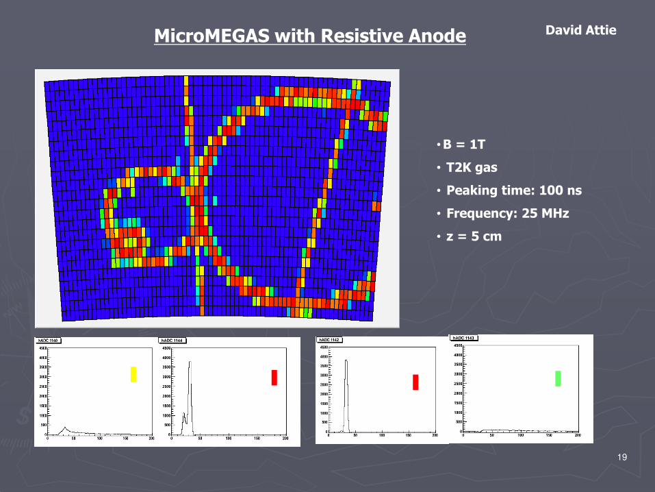
MicroMEGAS with Resistive Anode
• B = 1T
• T2K gas
• Peaking time: 100 ns
• Frequency: 25 MHz
• z = 5 cm
David Attie
19

MicroMEGASMicroMEGAS with Restive Anodewith Restive AnodeDouble Track separation and signals in time.Double Track separation and signals in time.
(Long duration of signals on side pads)20

σ(0) = 51.9µmNeff = 24.5 ±±±±0.5Cd====92.4±±±±0.4 µm/√cm
Asian GEM Module: Position Resolution
B=1T
Consistent with results from small prototype tests: σ(0) ~~~~ 52µm, Neff ~~~~24-25.Deviation from expectation in the large drift distances is due to the change of PCMAG field seen by MPGD module. At the time of beam test the PCMAG lifting stage was under preparation.
21

Asian GEM Asian GEM ModulesModules ++ 3,000ch3,000ch ALTRO ElectronicsALTRO ElectronicsBeam Beam Test Test in in Spring Spring 2009 w/o gating GEM2009 w/o gating GEM
With 25 cm long flat-flexible cables
22

Asian GEM Asian GEM ModulesModules ++ 3,000ch3,000ch ALTRO ElectronicsALTRO ElectronicsBeam Beam Test Test in in Spring Spring 2009 w/o gating GEM2009 w/o gating GEM
3,000ch ALTRO electronics distributed in a limited area along beamèèèè Missing track elements.
The noise level of ALTRO electronics is 340 electrons with the 25 cm longflexible flat cables.
One of the modules started to draw current due to theprovisional electrode on the frame of the top GEM in theabsence of the gating GEM. The rest (most) of the datataking was performed only with two modules.Missing gate GEM causes some distortion.
Practice of the LP1 goals No. 1 (!?) 23

“Demonstrate full“Demonstrate full--volume trucking in nonvolume trucking in non--uniform magnetic field, uniform magnetic field, trying to provide a proof for the momentum resolution at LC TPC”trying to provide a proof for the momentum resolution at LC TPC”
TPC Large Prototype Beam Test: LP1 in 2010TPC Large Prototype Beam Test: LP1 in 2010
2010:2010:Spring 3Spring 3--4 Asian GEM Modules w/ gating GEM (10,000ch ALTRO electronics)4 Asian GEM Modules w/ gating GEM (10,000ch ALTRO electronics)
DESY GEM modules (w/ wire gating?) (10,000ch ALTRO electronics)DESY GEM modules (w/ wire gating?) (10,000ch ALTRO electronics)Fall 7 Fall 7 MicroMEGASMicroMEGAS modules w/ resistive anode (12,000ch T2K electronics)modules w/ resistive anode (12,000ch T2K electronics)
MicroMEGAS modules in 2010
(Unfortunately T2K electronics can not be used at ILC TPC!)
Over sized electronic in 2008-2009
MicroMEGAS module
24

Two steps:
(1) σrφ: OK
ßßßß MPGD TPC ßßßß Gas of low diffusion (high ωτ):):):): Ar:CF4:Isobutene ((((T2K
gas)
Measurement of Momentum ResolutionLP 1
25
(2) Momentum resolution:
ßßßß Non uniformity of PCMAG magnetic field (in purpose àààà ILC)ßßßß Distortion of other sources: Field cage, endplateßßßß Distortion due to ion feedback (Ion disks)
à Tracking Software for the non uniform magnetic field (Urgent!)

TPC Large Prototype Beam Test (LP2) from 2011TPC Large Prototype Beam Test (LP2) from 2011Current Plan Current Plan
2010 2010 Continue LP1 test at DESY Continue LP1 test at DESY
2011 2011 Move to a Move to a high momentum high momentum hadronhadron beambeam::
ßßßßßßßß Limitation using electron beam to measure momentum.Limitation using electron beam to measure momentum.
àààààààà Options of magnetOptions of magnetMove the current PCMAGMove the current PCMAGFind a proper high filed magnet accommodates Find a proper high filed magnet accommodates
current current LP1 TPC (Solenoid preferable).LP1 TPC (Solenoid preferable).àààààààà Build also a new field cage with a laser track calibrationBuild also a new field cage with a laser track calibrationàààààààà With TPC “Advanced Endplate” (need resources!)With TPC “Advanced Endplate” (need resources!)
26

Two Important R&D Issues in 2010-2012
Advanced endplate:
Requirement: thickness 15% Xo
Thin endplateHigh density, low power electronics to match small pads
(1 x 4mm) surface-mounted directly on the back of pad plane of MPGD detector module
Power delivery, power pulsing and cooling
27
Power delivery, power pulsing and cooling
LP2 with Advanced endplate
Ion Feed back and Ion disks:
Ion feed back ration and beam backgrounds
Estimate distortion due to the ion disks (simulation)Options of gating device: Wire gating, GEM gatingMethods of calibration

Advanced Endplate: SAdvanced Endplate: S--ALTROALTROHigh density, low power , low material electronics for TPCHigh density, low power , low material electronics for TPC
ALICE TPCILC (ILD) TPC 28

Advanced Endplate: SAdvanced Endplate: S--ALTROALTROHigh density, low power electronics for TPCHigh density, low power electronics for TPC
29

Advanced Endplate: SAdvanced Endplate: S--ALTROALTROHigh density, low power electronics for TPCHigh density, low power electronics for TPC
30

Chip size: (*estimate)Shaping amplifier 0.2 mm2
ADC 0.7 mm2 (*)Digital processor 0.6 mm2 (*) When 1.5mm2/channel
64 ch/chip ~ 100 mm2
PCB board ~ 27 x 27 cm2
~16400 pads or 256 chips/boardBare die flip-chip mounted or chip scale packageMinimum-size capacitors (0.6x0.3x0.3mm3)Standard linear voltage regulators
L. MusaAdvanced Endplate: SAdvanced Endplate: S--ALTROALTROChip size and Power consumptionChip size and Power consumption
pad: 1 x 4mm2
31
Standard linear voltage regulatorsData link based on ALICE SPD GOL MCM
Power consumption: (*) 10 -40MHzAmplifier 8 mW/channelADC 12-34 mW/channel (*)Digital Proc 4 mW/channelPower reg. 2 mW/channel Data links 2 mW/channel Power reg. eff. 75%Total 32-60mW/channel (*)Duty cycle: 1.5% (Electrical duty)Average power 0.5 mW / channel
100 -200W/m2 (*)

Advanced Endplate: S-ALTROStatus and Schedule
32

Advanced Endplate: S-ALTRO Design of Pad Board
18 layer PAD PCB Option of Cooling: 2-phase CO2 cooling/traditional H2O cooling 33

Advanced Endplate: PCB Test Test with Dummy Pad PCB
Test:
Power switchingPower delivery Cooling:Thermo-mechanical test of pad PCB
Dummy Pad PCB:
S-ALTRO Team LC TPC groups
Dummy Pad PCB:
Realistic design of pad PCB with all components64ch S-ALTROs replaced by proper FPGAs and OP amp/ADC as
current load and heat source.Connect pads to the FPGA analog outputsTry cooling by the 2-phase CO2 cooling
(AMS and LHCB: Bart Verlaat/Nikhef)Test also digital software model/communication in FPGATest in high magnetic field
Schedule: 2010 34

Advanced Endplate: S-ALTRO Power switching
L. MussaT. Fusayasu
A case of digital power switching in ALICE
35

Advanced Endplate: CoolingThe option of the 2-phase CO2 cooling
Bart Verlaat/Nikhef
36
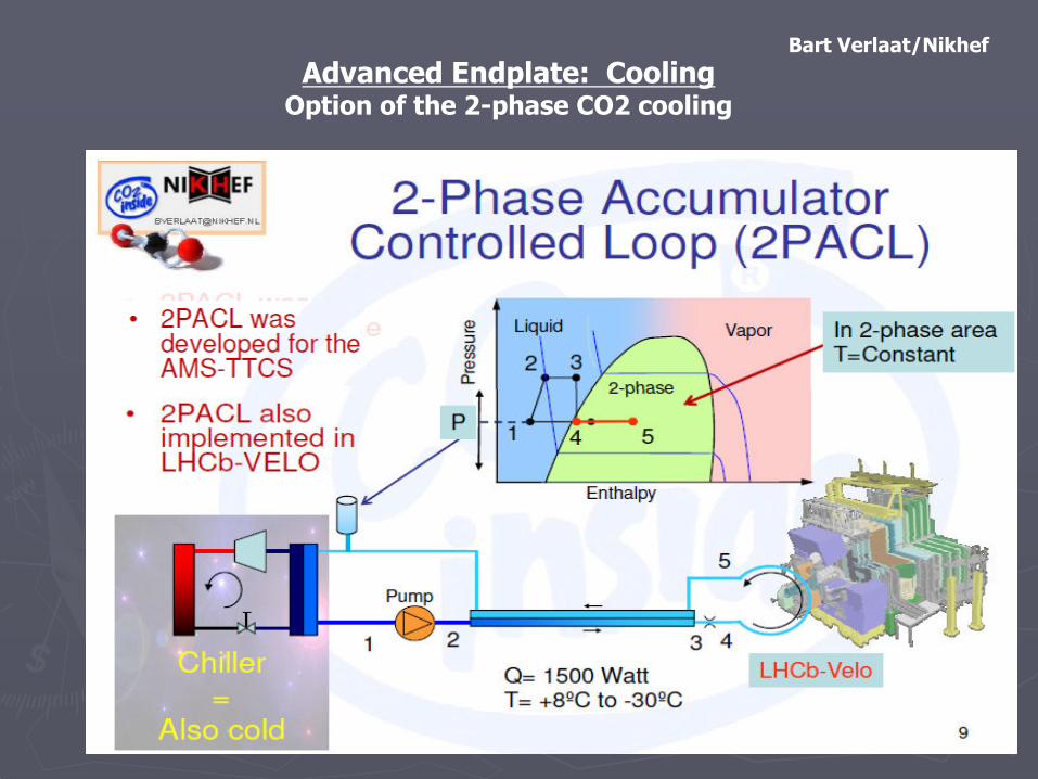
Advanced Endplate: CoolingOption of the 2-phase CO2 cooling
Bart Verlaat/Nikhef
37
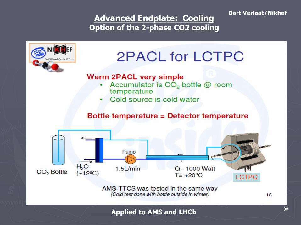
Advanced Endplate: CoolingOption of the 2-phase CO2 cooling
Bart Verlaat/Nikhef
Applied to AMS and LHCb 38

Advanced Endplate: CoolingPreliminary Design Consideration for ILC TPC
Advantage of thin piping (high pressure)
Bart Verlaat/Nikhef
39
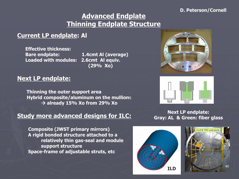
Advanced EndplateThinning Endplate Structure
Current LP endplate: Al
Effective thickness:Bare endplate: 1.4cmt Al (average)Loaded with modules: 2.6cmt Al equiv.
(29% Xo)
Next LP endplate:
Thinning the outer support area
D. Peterson/Cornell
Thinning the outer support areaHybrid composite/aluminum on the mullions
àààà already 15% Xo from 29% Xo
Study more advanced designs for ILC:
Composite (JWST primary mirrors) A rigid bonded structure attached to a
relatively thin gas-seal and module support structure
Space-frame of adjustable struts, etc
Next LP endplate:Gray: AL & Green: fiber glass
ILD40

Ions Feedback and Ion Disks
The ion feedback ratios
0.2-0.3% for MicroMEGAS and for a certain triple GEM configuration.
When MPGD gas gain < 1,000, the average density of feed back ions in the drift region is same to that of primary ions.
Ion disks: Ion disks:
Note that the density in ion disks higher by a factor of ~~~~ 200.
Urgently need to estimate the level of track distortion due to the disks by a full simulation for different background consitions(Thorsten Krautscheid/Bonn)
Still to complete Marlin TPC!41

Ion Feedback: Gating DeviceIon Feedback: Gating Device
Gating GEM Gating GEM ((By Asian LC TPC group)By Asian LC TPC group)
Stop ions at the level of 10Stop ions at the level of 10--4 only by the gating GEM.4 only by the gating GEM.
Transmission of primary electrons by special thin (14µmtTransmission of primary electrons by special thin (14µmt)))))))) gating GEM: gating GEM: 50% or less by simulation and measurements.50% or less by simulation and measurements.
Neff then becomes one half (20 Neff then becomes one half (20 àààààààà 10 for GEM, 30 10 for GEM, 30 àààààààà 15 for 15 for MicroMEGASMicroMEGAS) ) deteriorating positiondeteriorating position resolution at large drift distances. resolution at large drift distances. deteriorating positiondeteriorating position resolution at large drift distances. resolution at large drift distances.
Gating wire planeGating wire plane
Well established method.Well established method.
100% ion stopping and closed to 100% electron transmission.100% ion stopping and closed to 100% electron transmission.
Introduce mechanical complication MPGD detector modules. Introduce mechanical complication MPGD detector modules. Need design study, in particular, on the impact to material budget/dead space.Need design study, in particular, on the impact to material budget/dead space.
42

Ion Feedback: GatingIon Feedback: GatingA. Sugiyama
43

ConclusionsConclusions
MPGD TPC options at ILC (ILD) TPC provide a large number of spacepoints (200) with the excellent point resolution down to 100micronsover 2m drift distance. It is a truly-visual 3D tracker works in highmagnetic filed providing the performance necessary for theexperimentation at ILC.
The TPC Large Prototype test at DESY (LP1) by LC TPC collaborationusing the EUDET facility is being carried out successfully sinceNovember 2008.
44
We look forward to performing momentum measurement in nonuniform magnetic field of PCMAG with full length tracks in the multimodules setup in 2010.
From 2011 we plan to perform beam test with a high energy hadronbeam.
There are important engineering issues to realize MPGD TPC for ILC(ILD): R&D for the advanced endplate and R&Ds for ion feedback/gating devices.