re-processing gold tailings in south africa - sgs s.a./media/global/documents/technical...
TRANSCRIPT
2010
AN ECONOMIC AND ENVIRONMENTAL CASE FOR RE-PROCESSING GOLD TAILINGS IN SOUTH AFRICACHRISTOPHER A. FLEMING, JAMES A. BROWN - SGS AND MARIUS BOTHA
ABSTRACTThe technical and economic feasibility or re-processing hundreds of millions of tons of tailings in a number of historic gold tailings dams in the Witwatersrand area of South Africa is being investigated. The objective is to recover uranium and residual gold from the tailings, as well as to oxidize the sulphides to eliminate long term environmental liabilities associated with acid mine drainage. The tailings from the re-processing plant will be re-deposited in a new area far from urbanization, allowing for the rehabilitation of the real estate currently occupied by these historic tailings.
The first step in the process involves a mild-regrind and mild acid leach of the tailings (pH 2.5 to 3.0) to dissolve up to 40% of the uranium. This uranium is recovered directly from the pulp by resin in pulp (RIP) with a strong base resin. The RIP tails are then treated by flotation to recover a rougher pyrite concentrate, and flotation tailings that are discarded. The rougher concentrate is cleaned to produce a final pyrite concentrate and cleaner scavenger tailings, and the pyrite concentrate is oxidized in an autoclave to leach uranium and generate acid. The autoclave discharge is combined with the cleaner scavenger tails, and the acid and ferric ions generated in the autoclave are used to leach more uranium and oxidize more sulphide in the cleaner tails. The product from the concentrate leach circuit is processed by resin in pulp for uranium recovery, followed by neutralization, cyanidation and carbon in pulp for gold recovery.
The rougher float tails may be further treated to recover gold that was not recovered in flotation, but which had been liberated from the old dumps by natural oxidation of some of the pyrite over many decades. The float tails would be neutralized and treated by cyanidation and CIL to recover this liberated gold.
All parts of the flowsheet have been extensively tested in the laboratory, and the critical elements of flotation, pressure oxidation and resin in pulp have been demonstrated in pilot plants. The results of the hydrometallurgical investigations are presented here.
INTRODUCTION
The South African gold and uranium producer, Gold Fields Mining SA (Pty) Limited, is developing a flowsheet to treat historic tailings as well as current arisings from their gold operations, to recover uranium, acid and additional gold (the Driefontein project). In addition, the project will rehabilitate the real estate currently occupied by the historic tailings for alternative, productive land use, as well as eliminate sulphide and long term environmental issues related to acid generation.
The flowsheet that has been developed for the Driefontein project involves a mild acid leach (~pH 3) and resin in pulp to recover soluble uranium, followed by flotation of the sulphides (mainly pyrite) at pH 4.5 to produce a bulk rougher concentrate and rougher tailings. In one of the options investigated at the pre-feasibility stage, the rougher concentrate will be cleaned to produce a low grade pyrite concentrate and cleaner scavenger tailings, both of which will be processed to recover uranium and gold.
The pyrite concentrate will be treated by high temperature pressure oxidation (POX) in this flowsheet, to oxidize the sulphides to sulphates (mainly ferric sulphate and sulphuric acid) and liberate any gold and uranium locked in the pyrite. Uranium leaches under the oxidizing, acidic conditions prevailing in the autoclave, while gold remains in the leach residue.
The slurry discharge from the autoclave will then be combined with the cleaner scavenger tailings in a hot atmospheric leaching (AL) circuit, in which the acid and ferric ions generated during POX will be utilized to leach uranium and oxidize some of the pyrite in the cleaner tailings.
To recover the valuable metals, the atmospheric leach slurry will be partially neutralized to ~pH 3 with limestone and processed with a strong base resin in a second resin in pulp (RIP) plant to extract the uranium. This will be followed by further neutralization (to ~pH 10) with lime, cyanidation and carbon in pulp (CIP) to recover gold.
SGS MINERALS TECHNICAL PAPER 2010-03
2
A grinding/flotation pilot plant was operated at the SGS facilities in South Africa, to produce several hundred kilograms each of pyrite concentrate and scavenger tailings, which were then shipped to Canada for piloting of the downstream process at the SGS facilities in Lakefield, Ontario. The downstream POX, atmospheric leaching, neutralization and uranium RIP operations are the subject of this paper.
RESULTS AND DISCUSSION
POX BACkGROUND The main goal of POX in the Driefontein project is to effectively oxidize the sulphide minerals, liberating the gold locked in the pyrite grains, whilst at the same time generating sufficient sulphuric acid and ferric ions to leach the uranium values in the autoclave feed and in the cleaner scavenger tailings during the subsequent atmospheric leach. Another objective is to convert all the iron sulphide in the original rougher concentrate into benign hematite and sulphate compounds such as gypsum, thereby eliminating the long term environmental liabilities associated with the natural generation of acid mine drainage.
When pyrite is oxidized with oxygen in an autoclave, the main products are ferric sulphate and sulphuric acid in solution, along with hematite and basic iron sulphate in the solids. The sulphate ion is common to all the products except hematite, which is the most stable and generally the most desired iron product.
Oxidation Reactions
2FeS2 + 7O2 + 2H2O = 2FeSO4 + 2H2SO4 (1)
4FeSO4 + 2H2SO4 + O2 = 2Fe2(SO4)3 + 2H2O (2)
4FeS2 + 15O2 + 2H2O = 2Fe2(SO4)3 + 2H2SO4 (1) + (2) = (3)
Hydrolysis Reactions
Fe2(SO4)3 + 3H2O = Fe2O3 + 3H2SO4 (hematite) (4)
Fe2(SO4)3 + 2H2O = 2Fe(OH)SO4 + H2SO4 (basic iron sulphate) (5)
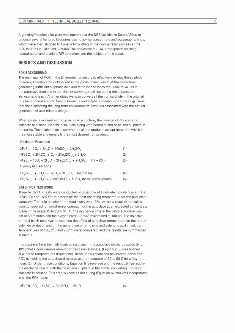
BATCH POX TESTwORk Three batch POX tests were conducted on a sample of Driefontein pyrite concentrate (17.4% Fe and 15% S2-) to determine the best operating temperature for the pilot plant autoclave. The pulp density of the feed slurry was 15%, which is close to the solids density required for autothermal operation of the autoclave at an expected concentrate grade in the range 15 to 20% S2- [1]. The residence time in the batch autoclave was set at 60 minutes and the oxygen pressure was maintained at 100 psi. The objective of the 3 batch tests was to examine the effect of autoclave temperature on the rate of sulphide oxidation and on the generation of ferric ions and sulphuric acid in solution. Temperatures of 190, 210 and 230OC were compared, and the results are summarized in Table 1.
It is apparent from the high levels of sulphate in the autoclave discharge solids (9 to 10%) that a considerable amount of basic iron sulphate, [Fe(OH)SO4], was formed at all three temperatures (Equation5). Basic iron sulphate can beObroken down after POX by holding the autoclave discharge at a temperature of 80 to 90 C for a few hours [2]. Under these conditions, Equation 5 is reversed and the residual free acid in the discharge reacts with the basic iron sulphate in the solids, converting it to ferric sulphate in solution. This step is know as hot curing (Equation 6), and was incorporated in all the POX tests:
2Fe(OH)SO4 + H2SO4 = Fe2(SO4)3 + 2H2O (6)
SGS MINERALS TECHNICAL BULLETIN 2010-03
3
The results of the batch tests allowed the following conclusions to be drawn:
• There was very little effect of temperature on POX performance in terms of sulphide oxidation (98 to 99% in 60 minutes) and uranium dissolution (97 to 98% in 60 minutes).
• The generation of ferric ions in solution decreased and acid production increased with increasing temperature. In addition, lower temperatures favoured the formation of basic iron sulphate precipitate, while higher temperatures favoured the formation of hematite, Fe2O3.
• As predicted from Equation 6, hot curing increased the concentration of ferric ions in solution, and decreased the concentrations of (i) acid in solution (ii) iron in the residue and (iii) sulphate in the residue.
A lower temperature would be preferred from a capital cost perspective, but the production of hematite and more acid at higher temperatures might be favoured from an operating cost perspective, depending on the consumption of acid by the cleaner tails in the atmospheric leach.
The results of the three batch tests were used to determine the influence of autoclave temperature and hot curing on the distribution of sulphate between sulphuric acid, ferric sulphate and basic iron sulphate, and on the distribution of iron in the residue between basic iron sulphate and hematite. The results are shown in Table 2.
The feed concentrate (17.4% Fe and 15% S2-) would theoretically have generated 450 kg SO4 per ton of autoclave feed, based on the 15% sulphide sulphur head assay. There was minimal mass loss after autoclaving, but about 20% of the residue mass was lost after hot curing.The following can be concluded from the results in Table 2:• The amount of sulphate analyzed in the autoclave products ranged from 430 to
460kg/t in the three tests, versus the theoretical amount of 450 kg/t, giving an excellent sulphate accountability of over 95%.
• The distribution of iron in the autoclave discharge indicated that most was in the
SOURCE TEMP SOLUTION PHASE SOLID PHASE EXTRACTION
Feed OC EMF Acid U Fe3+ U Fe S2- SO4U E Fe
mV g/L mg/L g/L g/t % % % % %
880 17.4 15.2 0.1
ACD 190 521 49 162 7.0 30 16.6 0.19 9.9 97.7 25.1
210 525 55 146 4.0 <20 18.5 0.29 9.4 >98 14.4
230 530 56 147 3.2 <20 19.0 0.18 8.4 >98 10.6
HCD 190 571 40 162 11.3 <20 14.2 0.14 1.1 >98 37.9
210 575 46 150 7.4 <20 17.0 0.24 1.1 >98 24.0
230 582 50 158 6.4 <20 18.3 0.21 0.9 >98 19.7
TEMP Fe DISTRIBUTION IN ACD SULPHATE MASS DISTRIBUTION (kG/T)OC Hem BFS FS H2SO4 Fe2(SO4)3 Fe(OH)SO4 Total
% % % ACD HCD* ACD HCD* ACD HCD* ACD HCD*
190 53 32 15 260 255 102 185 98 11 460 451
210 62 30 8 295 293 43 122 94 11 432 426
230 67 26 7 331 319 34 104 84 9 449 432
Table 1: Summary of results from the batch pressure oxidation of Driefontein pyrite concentrate containing gold and uranium
Table 2: Effect of autoclave temperature on the distribution of iron and sulphate products in the autoclave discharge.
ACD = autoclave discharge; HCD = hot cure discharge
Hem=hematite; BFS= basic *iron sulphate; FS = ferric sulphate; ACD= autoclave discharge, HCD = Hot cure discharge; Corrected for ~20% mass loss in hot curing;
form of hematite (50 - 75%), followed by basic iron sulphate (20 to 30%), with only about 10% in solution as ferric sulphate. The data suggested that ~90% of the basic iron sulphate decomposed to ferric sulphate in solution during hot curing, and there was no change in the amount of hematite (after correction for mass loss in hot curing).
• The proportion of hematite increased with increasing temperature, as expected, whilst both basic ferric sulphate and ferric sulphate decreased with increasing temperature.
• Most of the sulphate was converted to sulphuric acid (50 to 75%), and the percentage conversion increased with increasing temperature from ~50% at 190OC to 75% at 230OC. This was followed by ferric sulphate, which accounted for 10 to 20% of the sulphate in the autoclave discharge and 25 to 40% in the Hot Cure discharge. About 15 to 20% of the sulphate was in the form of basic iron sulphate in the autoclave discharge, and >90% of this decomposed to ferric sulphate in solution during hot curing. The proportions of both ferric sulphate in solution and basic iron sulphate in the residue decreased with increasing autoclave temperature.
SGS MINERALS TECHNICAL BULLETIN 2010-03
4
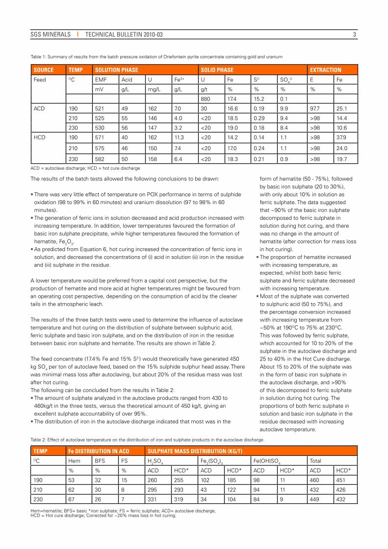
CONTINUOUS POX PILOTING The setup of the continuous autoclave at the SGS Mineral Services’ Lakefield site is depicted in Figure 1. The autoclave is a grade12 titanium, submarine-style, high pressure vessel, with an internal configuration consisting of six compartments, divided by weirs with staggered heights. The lower slurry levels are at the discharge end, and the slurry flows from one compartment to the next by gravity, through downcomers to avoid by-passing. The first and last compartments are about 50% larger in volume than the middle four compartments, and the total slurry volume of the autoclave at temperature is about 35L.
Each of the six compartments is equipped with its own sampling tube, whereby slurry samples can be withdrawn from the autoclave (by remotely actuated valves) into individual sample bombs, which are indirectly water-cooled. The feed to the autoclave is continuous by one of two (duty and standby) high pressure pumps, and the oxidized slurry discharges semi- continuously through a series of computer-controlled valves into a ~7L titanium letdown pot. The letdown pot is indirectly cooled by a cooling coil passing through the pot, to minimize flashing when the letdown pot is vented and drained.
Pure oxygen is supplied to the autoclave in bulk gas cylinders, and oxygen is added to the first five compartments at a flowrate that is controlled into each compartment individually by mass flow meters. Off-gas is drawn through one of two pressure control valves (duty and standby). The gas is passed through a series of condensers, and the non-condensable gases pass to gas analyzers.
Three continuous POX pilot plant campaigns were conducted with the Driefontein concentrates. Initially, two short campaigns (24 hours each) were run to confirm the batch results achieved earlier, and to evaluate the behaviour of low and medium grade sulphide feeds. The third campaign also used a fairly low sulphide grade feed material as the
Figure 1: Simplified POX flowsheet schematic
Table 3: Composition of flotation concentrates used in the continuous POX pilot plant campaigns
feed to POX, but was longer in duration than the first two (~72 hours), and incorporated the atmospheric leaching of cleaner flotation tails for the first time. Approximately equal masses of POX discharge slurry and cleaner scavenger tails were blended continuously and processed for the recovery of uranium. The composition of the 3 feeds is shown in Table 3, from which it can be seen that the sulphide grades of all the pilot plant feeds were significantly lower than the concentrate used for the batch tests.
The median temperature tested in the batch POX tests (200°C) was selected for all the continuous runs, and the feed pulp density was calculated based on the sulphide grade of the concentrates and the requirement for autothermal operation [1]. The residence time in the autoclave was generally 2 hours, except for the last 16 hours of the long run, when it was reduced to 1 hour. The main operating parameters selected for the three POX runs are summarized in Table 4.
SAMPLE U Au Fe S2-
g/t g/t % %
PP 1A 630 1.93 14.4 11.9
PP 1B 450 1.26 10.0 6.2
PP 2 490 1.66 12.4 7.6
Data from the three continuous autoclave runs are summarized in Table 5 and Figures 2 to 4, and the following conclusions can be drawn from the results: • Sulphide oxidation in the autoclave
was very efficient under all conditions tested (96- 99%, Figures 2 and 3), and the sulphide was oxidized all the way to sulphate (no elemental sulphur formation). The sulphate occurred mainly as ferric sulphate and free sulphuric acid in solution, along with 2 - 6% sulphate in the residue, mostly as basic iron sulphate and possibly some gypsum. There was less BFS formed in the pilot plant than in the batch tests, presumably because of the lower sulphide concentrate grades.
• Uranium dissolution in the autoclave was very efficient, with U in the solids being reduced from 500 - 600 g/t in the feed to less than 20 g/t in the POX residue (which was the detection limit of the XRF assay technique used to
SGS MINERALS TECHNICAL BULLETIN 2010-03

5
Table 4: Continuous POX pilot plant operating parameters
Table 5: Analyses of the pilot plant autoclave discharge
Figure 2: Rate of sulphide oxidation 1 in the pilot plant autoclave - POX PP 1A and PP 1B1 Sulphide oxidation expressed here simply as [1 - S2- in Residue / S2- in Feed] with no account for solids weight loss.
Figure 3: Rate of sulphide oxidation in the pilot plant autoclave- POX PP2
analyze the solids). This is equivalent to a uranium leach efficiency of > 96%. The uranium concentration in the POX liquor varied from 180 to 250 mg/L for the various feeds and the different pulp densities of the feeds.
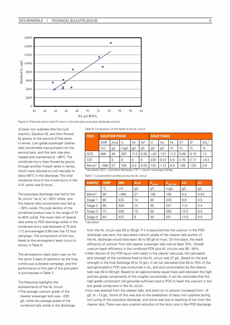
• The free acid concentration in the autoclave discharge varied from ~ 30 - 50 g/L, and the iron in solution varied from 4 to 12 g/L. The EMF of the autoclave discharge was generally between 475 and 500 mV (versus the Ag/AgCl saturated KCl electrode), and >90% of the iron in solution in the autoclave discharge was present as the ferric ion, proving that the feed concentrates were well oxidized in the autoclave. The wide variation in the concentration of iron in solution was due to the variation in the concentration of free acid in solution, which in turn varied with the composition of the feed concentrates and pulp density of the feed slurry. As can be seen from Figure 4, the concentration of iron in solution was a very sensitive function of the free acid concentration.
• The kinetic profile of the sulphide oxidation reaction (Figures 2 and 3) was determined by analyzing samples from each of the 6 compartments in the autoclave. The data indicated that a residence time of 120 minute was possibly excessive, since sulphide oxidation and uranium dissolution were essentially complete after the first 2 compartments (~45 minutes). However, during the last 16 hours of the second campaign, when the residence time was cut from 2 hours to 1 hour, sulphide oxidation efficiency decreased from ~99% to ~96% (Fig. 3), and uranium in the residue increased slightly, from < 20 g/t to 20 - 30 g/t.
• Although sulphide oxidation and uranium dissolution were essentially
complete in < 60 minutes, the concentration of iron in solution decreased steadily over the full 120 minutes in the autoclave, and the concentration of sulphuric acid increased steadily. This is due to the hydrolysis reaction in which ferric sulphate in solution is slowly converted to hematite and sulphuric acid (Equation 4). This is a desirable reaction, and might be some justification for longer residence times in the autoclave.
• Consideration could also be given to running the autoclave at pulp densities that are lower than needed for autothermal operation. This will lower the acid in solution, which will also promote the desirable formation of hematite. There is a cost to running the autoclave in this way, since heat has to be recovered from the let down and used to pre-heat the feed. But the savings that stem from the fact that more acid will be generated from the Equation 4 hydrolysis reaction (which is needed in AL) and less ferric sulphate
OPERATING PARAMETERS PP 1A PP 1B PP 2A PP 2B
Operating time hours 0 - 24 24 - 48 0 - 72
Sulphide grade % 11.9 6.2 7.6
Pulp Density w/w % 23 35 33.5
Feed rate dry kg/hr 4.4 6.4 7.7 14.9
Autoclave temp OC 200 200 200
Oxygen pressure
psi 100 100 100
Residence time min 120 120 120 60
RUN PULP AND SOLUTION PHASE SOLID RESIDUES
Pulp dens
EMF Acid U FeT Fe2+ U Au Fe ST S2- SO42-
% mV g/L mg/L g/L g/L g/t g/t % % % %
PP1A 18.4 608 46 180 7.9 0.45 <20 2.1 14 1.1 0.1 2.5
PP1B 25.5 550 31 195 1.8 0.14 <20 1.5 11 0.8 0.2 1.6
PP2A 30 490 52 250 12.4 1.10 <20 2.0 12 2.2 0.1 6.3
PP2B 30 480 46 240 7.5 0.81 30 1.7 11 2.6 0.4 6.5
is left in solution (which has little benefit, and carries a cost penalty in neutralization charges) could be significant.
ATMOSPHERIC LEACHING (AL) The hot autoclave discharge was combined with the cleaner scavenger float tailings in the AL circuit, where the acid and ferric ions generated in POX were used to leach uranium from the cleaner scavenger tailings. The autoclave discharge was held at ~90OC for 2.5 hours in the first tank of the AL circuit, to allow time for the breakdown
SGS MINERALS TECHNICAL BULLETIN 2010-03
6
of basic iron sulphate (the hot cure reaction, Equation 6), and then flowed by gravity to the second of five tanks in series. Low grade scavenger cleaner tails concentrate was pumped into the second tank, and this tank was also heated and maintained at ~90OC. The combined slurry then flowed by gravity through another 3 leach tanks in series, which were allowed to cool naturally to about 60OC in the discharge. The total residence time of the mixed slurry in the 4 AL tanks was 8 hours.
The autoclave discharge was fed to the AL circuit “as is”, at ~30% solids, and the cleaner tails concentrate was fed at ~ 50% solids. The pulp density of the combined product was in the range of 37 to 40% solids. The mass ratio of cleaner tails solids to POX discharge solids in the combined slurry was between 0.73 and 1.17, and averaged 0.89 over the 72 hour campaign. The composition of the two feeds to the atmospheric leach circuit is shown in Table 6.
The atmospheric leach plant was run for the same 3 days of operation as the long continuous autoclave campaign, and the performance of this part of the pilot plant is summarized in Table 7.
The following highlights the achievements of the AL circuit:• The average uranium grade of the
cleaner scavenger tails was ~220 g/t, while the average grade of the combined tails solids in the discharge
Figure 4: Free acid versus total Fe tenor in the pilot plant autoclave discharge solution
Table 6: Composition of the feeds to the AL circuit
Table 7: Concentration profiles across the AL circuit
*calculated, ACD = autoclave discharge; CST = cleaner scavenger tailings
*calculated
FEED SOLUTION PHASE SOLID PHASE
EMF Acid U FeT Fe2+ U Au Fe ST S2- SO42-
mV g/L mg/L g/L g/L g/t g/t % % % %
ACD 486 46 267 11.2 0.92 <20 1.51 11.3 0.68 0.15 1.3
CST 0 0 0 0 230 0.57 5.9 2.76 2.17 <0.4
Blend* ~480 27 155 6.5 0.53 135 1.13 8.9 1.89 1.29 0.8
SAMPLE TEMP EMF Acid USOLIDS USOLUTION FeT Fe2+
OC mV g/L g/t mg/L g/L g/L
Blend* 90 ~480 27 135 155 6.5 0.53
Stage 1 90 433 14 40 235 9.9 4.5
Stage 2 80 428 13 30 251 11.3 5.4
Stage 3 72 426 13 30 260 12.0 6.0
Stage 4 64 423 8 20 251 13.0 6.0
from the AL circuit was 20 to 30 g/t. If it is assumed that the uranium in the POX discharge was zero, the calculated uranium grade of the cleaner tails portion of the AL discharge would have been 40 to 60 g/t at most. On this basis, the leach efficiency of uranium from the cleaner scavenger tails was at least 75%. Overall uranium leach efficiency in the combined POX plus AL circuits was 90 - 94%.
• After dilution of the POX liquor with water in the cleaner tails pulp, the calculated acid strength of the combined feed to the AL circuit was 27 g/L. Based on the acid strength in the final discharge (8 to 12 g/L), it can be calculated that 60 to 70% of the acid generated in POX was consumed in AL, and acid consumption by the cleaner tails was 50 to 60 kg/t. Based on an approximately equal mass split between the high and low grade components of the rougher concentrate, it can be concluded that the high grade component will generate sufficient acid in POX to leach the uranium in the low grade component in the AL circuit.
• Iron was leached from the cleaner tails, and total iron in solution increased from ~6 g/L to ~13 g/L. Some of this was due to the breakdown of basic iron sulphate during hot curing of the autoclave discharge, and some was due to leaching of iron from the cleaner tails. There was also a partial reduction of the ferric ions in the POX discharge
SGS MINERALS TECHNICAL BULLETIN 2010-03
7
Table 8: Extent of metal precipitation and ferrous oxidation during neutralization
to ferrous, and a steady decrease in EMF across the 4 leach tanks, from >500 mV in the AL feed to ~ 420 mV in the AL discharge. The Fe3+/Fe2+ ratio decreased from about 10:1 in the feed to the AL circuit to ~2:1 in the discharge.
• Concentration profiles across the 4 AL leach tanks (Table 7) for acid, ferric, ferrous and uranium (solution and solids) indicated that most of the leaching occurred in the first and second leach tanks, and it is possible that the AL leach residence time could be reduced with finer tuning of the operating conditions.
NEUTRALIzATION The combined leach slurry from the AL circuit was thoroughly blended and stored for several weeks, and was then processed continuously (in two 10-day campaigns) through a circuit consisting of partial neutralization followed by resin in pulp uranium recovery. The AL discharge was neutralized to pH 2.7-3.2 with finely ground limestone slurry to precipitate ferric hydroxide and minimize iron adsorption on the resin in the RIP contactors. However, almost half the iron in the AL discharge was in the ferrous form (Table 7) and this iron remained in solution at pH 3. The ferrous then oxidized slowly to ferric in the RIP contactors and loaded onto the resin. Therefore, an attempt was made to remove the total soluble iron ahead of RIP, by oxidizing the leach slurry with gaseous oxygen to convert ferrous to ferric. But ferrous oxidation with oxygen was very slow and inefficient at ~pH 3, and was replaced after a few days of pilot plant operation with oxidation by hydrogen peroxide.
The inefficiency of oxygen in this oxidation step was an artefact of the small scale of the pilot plant tanks. In large commercial tanks, the higher hydrostatic head pressure will increase
the dissolved oxygen concentration, and custom-designed mixing systems will maximize gas mass transfer. This might provide an adequate rate of oxidation, which could always be augmented by using oxygen in combination with SO2. This will likely be a more cost effective method of oxidizing ferrous than hydrogen peroxide.
The optimum conditions that were established during the pilot plant involved neutralization with limestone to a pH of 3.0 to 3.2, addition of peroxide to an EMF of 550 to 600 mV (vs. Ag|AgCl saturated KCl electrode) and mild temperature (~35-50°C). Under these conditions, 98% of the iron was precipitated (from ~10 g/L in the combined leach slurry to ~150 mg/L in RIP feed) with limestone additions of ~45 kg/t (combined leach solids) and a peroxide dose of ~15 kg/t (as equivalent 100% H2O2). These conditions also led to roughly two thirds of the dissolved silicon in the combined leach solution being precipitated. The precipitation of metals in the neutralization circuit is summarized in Table 8.
Between 10 and 16% of the leached uranium also precipitated in the neutralization tanks (based on solution assays). However, it became clear during the campaign that any uranium precipitated in the neutralization circuit was remobilized in RIP and recovered on the resin. Evidence for this was provided by the observation that uranium losses to the RIP tails solids remained below the analytical detection limit of 20 g/t throughout the campaign. This allowed the pH set point of the feed to RIP to be increased from ~2.8 at the start of the campaign to ~3.2 for the second half, which maximized iron precipitation and uranium recovery efficiency. This also increased the amount of Si removed in the neutralization tanks. Removing most of the iron and some of the silica ahead
of RIP allowed the RIP plant to achieve very high uranium loadings of 70-75 g/L on the resin, from a solution feed concentration of only ~150 mg/L.
RESIN IN PULP Two integrated neutralization/RIP ten day campaigns were run (PP1 and PP2), with a gap of about a month between them, to give time for the analysis and compilation of data from PP1 before re-adjusting the RIP operating conditions for PP 2 (should this prove necessary). Uranium was recovered from solution with the strong base resin, Purolite A660, in 6 RIP contactors, with a total slurry residence time of between 3 and 4 hours. The resin was advanced counter-current to the direction of slurry flow every 12 hours, by advancing all the cells in the RIP train. The loaded resin in the lead cell was recovered by discharging the contents of this tank over a 35 mesh screen, which retained the resin and allowed the slurry to flow through. The washed, loaded resin was transferred to the elution section, while the slurry was pumped slowly back into the RIP circuit by including it in the feed to the first RIP tank. The RIP slurry feed line was then moved to the next RIP cell (which becomes the ‘new’ lead cell) and an empty cell, containing a fresh batch of either new or recycled eluted resin or a combination of the two, was placed in the ‘old’ lead cell position, which then became the cell from which the RIP tailings were pumped. This “carousel” mode of operation is a simulation of a Kemix Pumpcell plant, which holds a number of advantages for uranium resin in pulp [3], and which has recently been commercialized by the Australian mining company, Paladin, at their Kayelekera operation in Malawi.
Resin breakage can be a problem in small pilot plant RIP tanks, and to avoid attrition of the resin beads, the slurry in the RIP tanks was agitated gently with a large flat paddle impeller, and limited
OPERATING PERIOD METAL PRECIPITATED (%) Fe2+ OXIDIzED
OXIDANT
U Fe Si Ni Co Cu zn
20/10 26/10 26 53 28 5 1 6 0 13 O2
26/10 31/10 14 97 33 5 0 11 3 96 H2O2
01/12 10/12 10 98 65 1 0 10 1 98 H2O2
SGS MINERALS TECHNICAL BULLETIN 2010-03
8
to the mixing required to keep the solids suspended. This was a successful strategy, and no broken resin beads were detected (by eye or under a microscope) after 3 weeks of RIP operation.
The Purolite A660 resin was received in the chloride form, and was converted to the sulphate form prior to pilot plant testing. A wet screen analysis performed on a sample of the resin confirmed it was a coarse bead product, with 97% of the beads larger than 600 µm and 83% larger than 850 µm. The particle size of the resin was also quite uniform, and there were very few broken beads.
The compositions of the aqueous phase of the slurry for the first (PP1) and second halves (PP2) of the campaign are listed in Table 9. The biggest difference in the feed compositions was the much lower concentration of iron in solution during PP2, and also the lower dissolved silica compared to PP1.
The counter current pulp to resin flow ratio was gradually ramped up over the campaign, from about 350 to 500. Uranium loading on the resin increased from ~ 40 g/L to ~75 g/L, with consistently low barren solution uranium tenors (< 1 mg/L) in the RIP tailings solution being maintained throughout. Generally, all of the uranium in solution was extracted by the 5th contactor.
The circuit started up with a pulp flow rate of about 7 L/h and with 250 mL of wet settle resin in each contactor, which was advanced every 12 hours. This resulted in a pulp to resin flow ratio of about 350, which yielded a target loading on the resin of 40 - 50 g/L uranium. Uranium extraction efficiency was excellent throughout this period, with the RIP pilot plant producing barrens solution losses of < 1 mg/L U in 5 RIP stages. Once the iron and silica levels in the feed to RIP were lowered after PP1, it was realized that higher uranium loading on the resin could be achieved. Therefore, the amount of resin in each stage was initially reduced to 200 mL, which increased the pulp to resin flow ratio to 450, and increased the target uranium loading on the resin to ~ 60 g/L U. Finally, towards the end of the campaign, the amount of resin was
CAMPAIGN pH EMF U FeT Fe2+ Si
mV mg/L mg/L mg/L mg/L
PP1 2.93 409 150 2570 2130 754
PP2 3.28 481 145 140 65 330
Table 9: Composition of the solution phase of the feeds to RIP
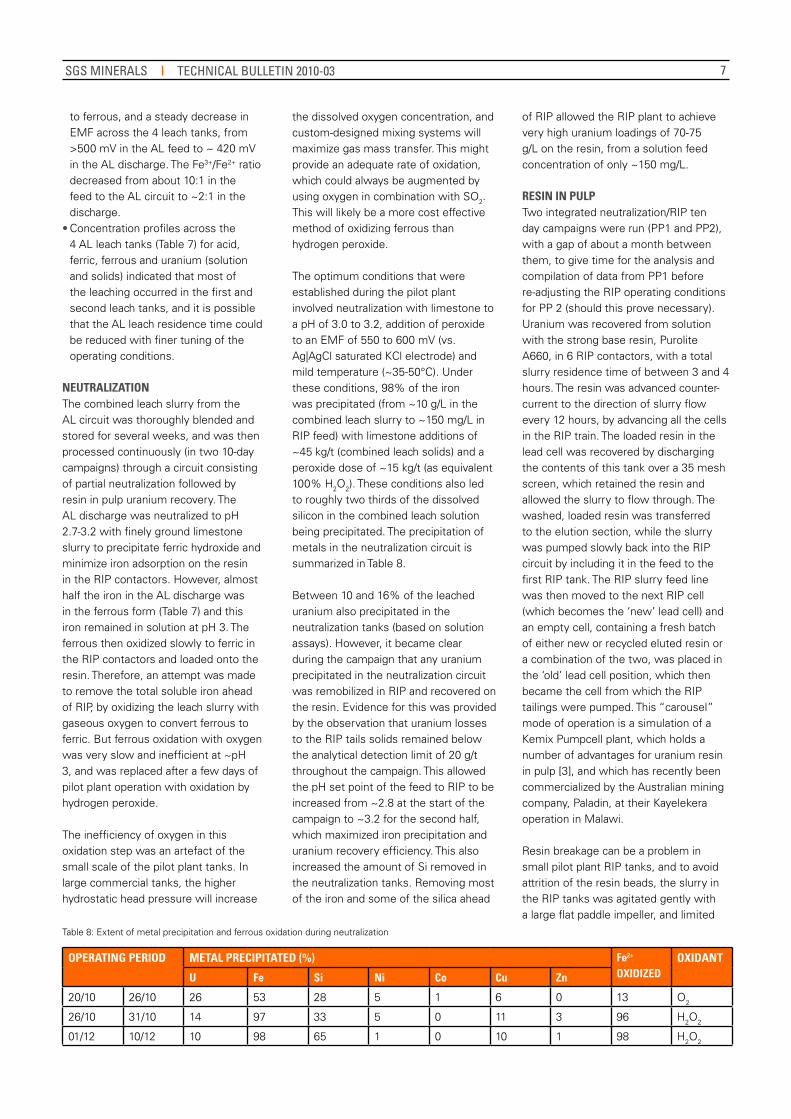
Figure 5: Uranium concentrations in the RIP barren solution
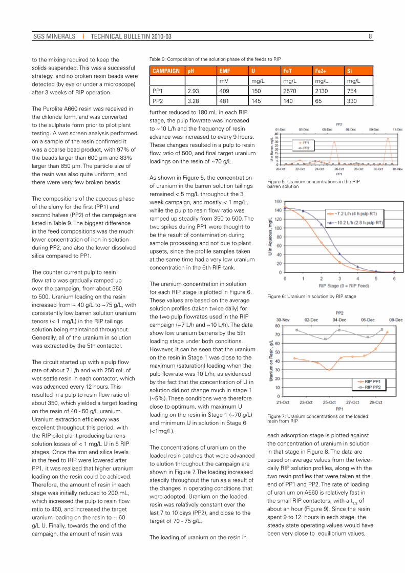
Figure 6: Uranium in solution by RIP stage
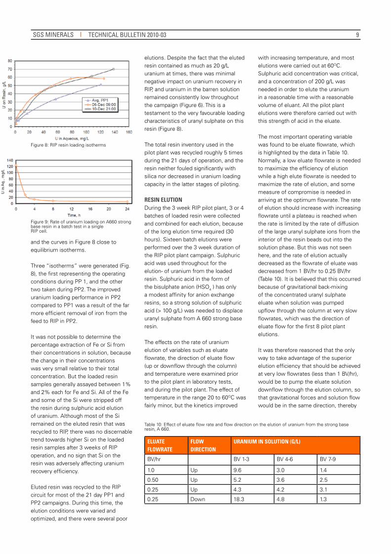
Figure 7: Uranium concentrations on the loaded resin from RIP
further reduced to 180 mL in each RIP stage, the pulp flowrate was increased to ~10 L/h and the frequency of resin advance was increased to every 9 hours. These changes resulted in a pulp to resin flow ratio of 500, and final target uranium loadings on the resin of ~70 g/L.
As shown in Figure 5, the concentration of uranium in the barren solution tailings remained < 5 mg/L throughout the 3 week campaign, and mostly < 1 mg/L, while the pulp to resin flow ratio was ramped up steadily from 350 to 500. The two spikes during PP1 were thought to be the result of contamination during sample processing and not due to plant upsets, since the profile samples taken at the same time had a very low uranium concentration in the 6th RIP tank.
The uranium concentration in solution for each RIP stage is plotted in Figure 6. These values are based on the average solution profiles (taken twice daily) for the two pulp flowrates used in the RIP campaign (~7 L/h and ~10 L/h). The data show low uranium barrens by the 5th loading stage under both conditions. However, it can be seen that the uranium on the resin in Stage 1 was close to the maximum (saturation) loading when the pulp flowrate was 10 L/hr, as evidenced by the fact that the concentration of U in solution did not change much in stage 1 (~5%). These conditions were therefore close to optimum, with maximum U loading on the resin in Stage 1 (~70 g/L) and minimum U in solution in Stage 6 (<1mg/L).
The concentrations of uranium on the loaded resin batches that were advanced to elution throughout the campaign are shown in Figure 7. The loading increased steadily throughout the run as a result of the changes in operating conditions that were adopted. Uranium on the loaded resin was relatively constant over the last 7 to 10 days (PP2), and close to the target of 70 - 75 g/L.
The loading of uranium on the resin in
each adsorption stage is plotted against the concentration of uranium in solution in that stage in Figure 8. The data are based on average values from the twice-daily RIP solution profiles, along with the two resin profiles that were taken at the end of PP1 and PP2. The rate of loading of uranium on A660 is relatively fast in the small RIP contactors, with a t1/2 of about an hour (Figure 9). Since the resin spent 9 to 12 hours in each stage, the steady state operating values would have been very close to equilibrium values,
SGS MINERALS TECHNICAL BULLETIN 2010-03
9
Figure 8: RIP resin loading isotherms
Figure 9: Rate of uranium loading on A660 strong base resin in a batch test in a single RIP cell.
Table 10: Effect of eluate flow rate and flow direction on the elution of uranium from the strong base resin, A 660.
and the curves in Figure 8 close to equilibrium isotherms.
Three “isotherms” were generated (Fig. 8), the first representing the operating conditions during PP 1, and the other two taken during PP2. The improved uranium loading performance in PP2 compared to PP1 was a result of the far more efficient removal of iron from the feed to RIP in PP2.
It was not possible to determine the percentage extraction of Fe or Si from their concentrations in solution, because the change in their concentrations was very small relative to their total concentration. But the loaded resin samples generally assayed between 1% and 2% each for Fe and Si. All of the Fe and some of the Si were stripped off the resin during sulphuric acid elution of uranium. Although most of the Si remained on the eluted resin that was recycled to RIP, there was no discernable trend towards higher Si on the loaded resin samples after 3 weeks of RIP operation, and no sign that Si on the resin was adversely affecting uranium recovery efficiency.
Eluted resin was recycled to the RIP circuit for most of the 21 day PP1 and PP2 campaigns. During this time, the elution conditions were varied and optimized, and there were several poor
elutions. Despite the fact that the eluted resin contained as much as 20 g/L uranium at times, there was minimal negative impact on uranium recovery in RIP, and uranium in the barren solution remained consistently low throughout the campaign (Figure 6). This is a testament to the very favourable loading characteristics of uranyl sulphate on this resin (Figure 8).
The total resin inventory used in the pilot plant was recycled roughly 5 times during the 21 days of operation, and the resin neither fouled significantly with silica nor decreased in uranium loading capacity in the latter stages of piloting.
RESIN ELUTION During the 3 week RIP pilot plant, 3 or 4 batches of loaded resin were collected and combined for each elution, because of the long elution time required (30 hours). Sixteen batch elutions were performed over the 3 week duration of the RIP pilot plant campaign. Sulphuric acid was used throughout for the elution- of uranium from the loaded resin. Sulphuric acid in the form of the bisulphate anion (HSO4 ) has only a modest affinity for anion exchange resins, so a strong solution of sulphuric acid (> 100 g/L) was needed to displace uranyl sulphate from A 660 strong base resin.
The effects on the rate of uranium elution of variables such as eluate flowrate, the direction of eluate flow (up or downflow through the column) and temperature were examined prior to the pilot plant in laboratory tests, and during the pilot plant. The effect of temperature in the range 20 to 60OC was fairly minor, but the kinetics improved
with increasing temperature, and most elutions were carried out at 60OC. Sulphuric acid concentration was critical, and a concentration of 200 g/L was needed in order to elute the uranium in a reasonable time with a reasonable volume of eluant. All the pilot plant elutions were therefore carried out with this strength of acid in the eluate.
The most important operating variable was found to be eluate flowrate, which is highlighted by the data in Table 10. Normally, a low eluate flowrate is needed to maximize the efficiency of elution while a high elute flowrate is needed to maximize the rate of elution, and some measure of compromise is needed in arriving at the optimum flowrate. The rate of elution should increase with increasing flowrate until a plateau is reached when the rate is limited by the rate of diffusion of the large uranyl sulphate ions from the interior of the resin beads out into the solution phase. But this was not seen here, and the rate of elution actually decreased as the flowrate of eluate was decreased from 1 BV/hr to 0.25 BV/hr (Table 10). It is believed that this occurred because of gravitational back-mixing of the concentrated uranyl sulphate eluate when solution was pumped upflow through the column at very slow flowrates, which was the direction of eluate flow for the first 8 pilot plant elutions.
It was therefore reasoned that the only way to take advantage of the superior elution efficiency that should be achieved at very low flowrates (less than 1 BV/hr), would be to pump the eluate solution downflow through the elution column, so that gravitational forces and solution flow would be in the same direction, thereby
ELUATE FLOwRATE
FLOw DIRECTION
URANIUM IN SOLUTION (G/L)
BV/hr BV 1-3 BV 4-6 BV 7-9
1.0 Up 9.6 3.0 1.4
0.50 Up 5.2 3.6 2.5
0.25 Up 4.3 4.2 3.1
0.25 Down 18.3 4.8 1.3
SGS MINERALS TECHNICAL BULLETIN 2010-03
10
preventing back-mixing. This was very successful, as shown in Table 10, and this method became the standard for the final 8 pilot plant elutions.
The other change that was made after the first RIP campaign was then introduction of a selective pre-elution of iron from the resin with sulphurous acid. Although Fe comes off the resin faster than uranium when eluting with strong sulphuric acid, the separation between the two metals was not “clean” and the uranium eluate solution was highly contaminated with iron. Sulphurous acid is too weak to elute uranium, but is a highly effective eluant for iron because ferric sulphate on the resin is reduced to ferrous sulphate, which has no affinity for anion exchange resins.
The best elution conditions were therefore only established during the second RIP campaign, and are exemplified in the performance in the last 3 elutions that were carried out (Table 11). In each of these elutions, the loaded resin was first eluted with 6 BVs of 6% sulphurous acid at a flowrate of 1BV/hr, which stripped the iron quantitatively and very selectively from the resin. This was followed by uranium elution, which comprised dripping 6BVs of 200 g/L sulphuric acid downflow through a column of loaded resin at 0.25 BVs/hr. The two stages of elution therefore took a combined 30 hours.
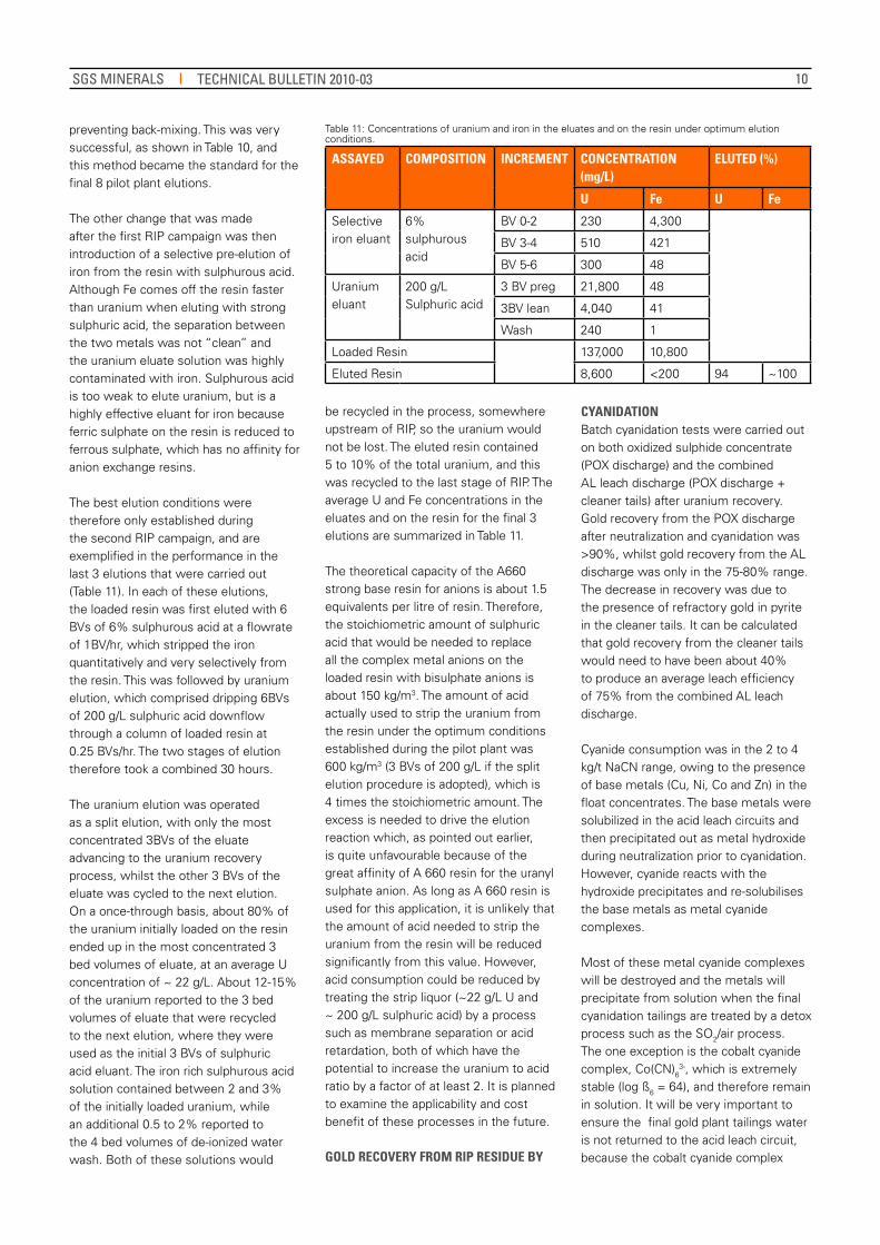
The uranium elution was operated as a split elution, with only the most concentrated 3BVs of the eluate advancing to the uranium recovery process, whilst the other 3 BVs of the eluate was cycled to the next elution. On a once-through basis, about 80% of the uranium initially loaded on the resin ended up in the most concentrated 3 bed volumes of eluate, at an average U concentration of ~ 22 g/L. About 12-15% of the uranium reported to the 3 bed volumes of eluate that were recycled to the next elution, where they were used as the initial 3 BVs of sulphuric acid eluant. The iron rich sulphurous acid solution contained between 2 and 3% of the initially loaded uranium, while an additional 0.5 to 2% reported to the 4 bed volumes of de-ionized water wash. Both of these solutions would
ASSAyED COMPOSITION INCREMENT CONCENTRATION (mg/L)
ELUTED (%)
U Fe U Fe
Selective iron eluant
6% sulphurous acid
BV 0-2 230 4,300
BV 3-4 510 421
BV 5-6 300 48
Uranium eluant
200 g/L Sulphuric acid
3 BV preg 21,800 48
3BV lean 4,040 41
Wash 240 1
Loaded Resin 137,000 10,800
Eluted Resin 8,600 <200 94 ~100
Table 11: Concentrations of uranium and iron in the eluates and on the resin under optimum elution conditions.
be recycled in the process, somewhere upstream of RIP, so the uranium would not be lost. The eluted resin contained 5 to 10% of the total uranium, and this was recycled to the last stage of RIP. The average U and Fe concentrations in the eluates and on the resin for the final 3 elutions are summarized in Table 11.
The theoretical capacity of the A660 strong base resin for anions is about 1.5 equivalents per litre of resin. Therefore, the stoichiometric amount of sulphuric acid that would be needed to replace all the complex metal anions on the loaded resin with bisulphate anions is about 150 kg/m3. The amount of acid actually used to strip the uranium from the resin under the optimum conditions established during the pilot plant was 600 kg/m3 (3 BVs of 200 g/L if the split elution procedure is adopted), which is 4 times the stoichiometric amount. The excess is needed to drive the elution reaction which, as pointed out earlier, is quite unfavourable because of the great affinity of A 660 resin for the uranyl sulphate anion. As long as A 660 resin is used for this application, it is unlikely that the amount of acid needed to strip the uranium from the resin will be reduced significantly from this value. However, acid consumption could be reduced by treating the strip liquor (~22 g/L U and ~ 200 g/L sulphuric acid) by a process such as membrane separation or acid retardation, both of which have the potential to increase the uranium to acid ratio by a factor of at least 2. It is planned to examine the applicability and cost benefit of these processes in the future.
GOLD RECOVERy FROM RIP RESIDUE By
CyANIDATION Batch cyanidation tests were carried out on both oxidized sulphide concentrate (POX discharge) and the combined AL leach discharge (POX discharge + cleaner tails) after uranium recovery. Gold recovery from the POX discharge after neutralization and cyanidation was >90%, whilst gold recovery from the AL discharge was only in the 75-80% range. The decrease in recovery was due to the presence of refractory gold in pyrite in the cleaner tails. It can be calculated that gold recovery from the cleaner tails would need to have been about 40% to produce an average leach efficiency of 75% from the combined AL leach discharge.
Cyanide consumption was in the 2 to 4 kg/t NaCN range, owing to the presence of base metals (Cu, Ni, Co and Zn) in the float concentrates. The base metals were solubilized in the acid leach circuits and then precipitated out as metal hydroxide during neutralization prior to cyanidation. However, cyanide reacts with the hydroxide precipitates and re-solubilises the base metals as metal cyanide complexes.
Most of these metal cyanide complexes will be destroyed and the metals will precipitate from solution when the final cyanidation tailings are treated by a detox process such as the SO2/air process. The one exception is the cobalt cyanide complex, Co(CN)6
3-, which is extremely stable (log ß6 = 64), and therefore remain in solution. It will be very important to ensure the final gold plant tailings water is not returned to the acid leach circuit, because the cobalt cyanide complex
SGS MINERALS TECHNICAL BULLETIN 2010-03
11
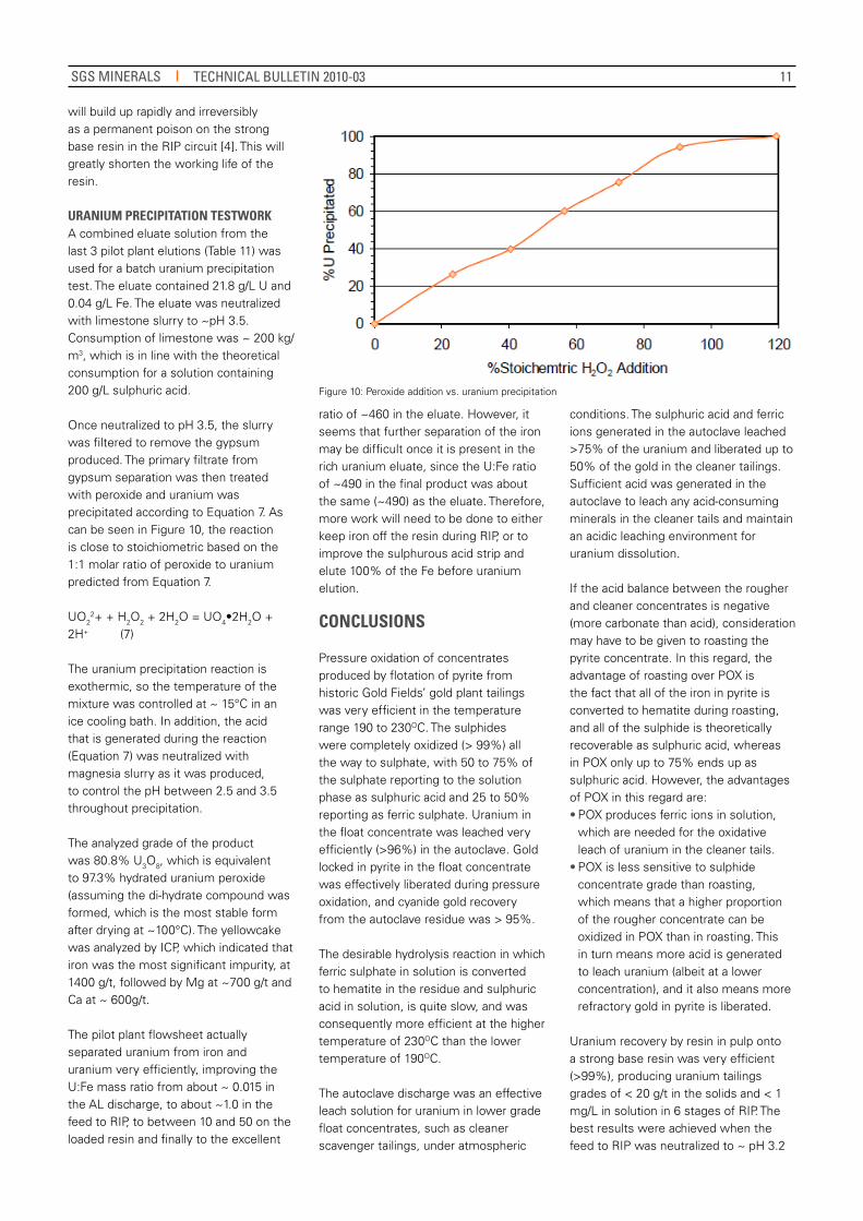
Figure 10: Peroxide addition vs. uranium precipitation
will build up rapidly and irreversibly as a permanent poison on the strong base resin in the RIP circuit [4]. This will greatly shorten the working life of the resin.
URANIUM PRECIPITATION TESTwORk A combined eluate solution from the last 3 pilot plant elutions (Table 11) was used for a batch uranium precipitation test. The eluate contained 21.8 g/L U and 0.04 g/L Fe. The eluate was neutralized with limestone slurry to ~pH 3.5. Consumption of limestone was ~ 200 kg/m3, which is in line with the theoretical consumption for a solution containing 200 g/L sulphuric acid.
Once neutralized to pH 3.5, the slurry was filtered to remove the gypsum produced. The primary filtrate from gypsum separation was then treated with peroxide and uranium was precipitated according to Equation 7. As can be seen in Figure 10, the reaction is close to stoichiometric based on the 1:1 molar ratio of peroxide to uranium predicted from Equation 7.
UO22+ + H2O2 + 2H2O = UO4•2H2O +
2H+ (7)
The uranium precipitation reaction is exothermic, so the temperature of the mixture was controlled at ~ 15°C in an ice cooling bath. In addition, the acid that is generated during the reaction (Equation 7) was neutralized with magnesia slurry as it was produced, to control the pH between 2.5 and 3.5 throughout precipitation.
The analyzed grade of the product was 80.8% U3O8, which is equivalent to 97.3% hydrated uranium peroxide (assuming the di-hydrate compound was formed, which is the most stable form after drying at ~100°C). The yellowcake was analyzed by ICP, which indicated that iron was the most significant impurity, at 1400 g/t, followed by Mg at ~700 g/t and Ca at ~ 600g/t.
The pilot plant flowsheet actually separated uranium from iron and uranium very efficiently, improving the U:Fe mass ratio from about ~ 0.015 in the AL discharge, to about ~1.0 in the feed to RIP, to between 10 and 50 on the loaded resin and finally to the excellent
ratio of ~460 in the eluate. However, it seems that further separation of the iron may be difficult once it is present in the rich uranium eluate, since the U:Fe ratio of ~490 in the final product was about the same (~490) as the eluate. Therefore, more work will need to be done to either keep iron off the resin during RIP, or to improve the sulphurous acid strip and elute 100% of the Fe before uranium elution.
CONCLUSIONS
Pressure oxidation of concentrates produced by flotation of pyrite from historic Gold Fields’ gold plant tailings was very efficient in the temperature range 190 to 230OC. The sulphides were completely oxidized (> 99%) all the way to sulphate, with 50 to 75% of the sulphate reporting to the solution phase as sulphuric acid and 25 to 50% reporting as ferric sulphate. Uranium in the float concentrate was leached very efficiently (>96%) in the autoclave. Gold locked in pyrite in the float concentrate was effectively liberated during pressure oxidation, and cyanide gold recovery from the autoclave residue was > 95%.
The desirable hydrolysis reaction in which ferric sulphate in solution is converted to hematite in the residue and sulphuric acid in solution, is quite slow, and was consequently more efficient at the higher temperature of 230OC than the lower temperature of 190OC.
The autoclave discharge was an effective leach solution for uranium in lower grade float concentrates, such as cleaner scavenger tailings, under atmospheric
conditions. The sulphuric acid and ferric ions generated in the autoclave leached >75% of the uranium and liberated up to 50% of the gold in the cleaner tailings. Sufficient acid was generated in the autoclave to leach any acid-consuming minerals in the cleaner tails and maintain an acidic leaching environment for uranium dissolution.
If the acid balance between the rougher and cleaner concentrates is negative (more carbonate than acid), consideration may have to be given to roasting the pyrite concentrate. In this regard, the advantage of roasting over POX is the fact that all of the iron in pyrite is converted to hematite during roasting, and all of the sulphide is theoretically recoverable as sulphuric acid, whereas in POX only up to 75% ends up as sulphuric acid. However, the advantages of POX in this regard are:• POX produces ferric ions in solution,
which are needed for the oxidative leach of uranium in the cleaner tails.
• POX is less sensitive to sulphide concentrate grade than roasting, which means that a higher proportion of the rougher concentrate can be oxidized in POX than in roasting. This in turn means more acid is generated to leach uranium (albeit at a lower concentration), and it also means more refractory gold in pyrite is liberated.
Uranium recovery by resin in pulp onto a strong base resin was very efficient (>99%), producing uranium tailings grades of < 20 g/t in the solids and < 1 mg/L in solution in 6 stages of RIP. The best results were achieved when the feed to RIP was neutralized to ~ pH 3.2
SGS MINERALS TECHNICAL BULLETIN 2010-03
12
© 2011 SGS. All rights reserved. The information contained herein is provided “as is” and SGS does not warrant that it will be error-free or will meet any particular criteria of per-formance or quality. Do not quote or refer any information herein without SGS’ prior written consent. Any unautho-rized alteration, forgery or falsification of the content or appearance of this document is unlawful and offenders may be prosecuted to the fullest extent of the law.
Presented at: 42nd Annual Meeting of the Canadian Mineral Processors, January 19 to 21, 2010, Ottawa, Ontario, Canada
CONTACT INFORMATION
Email us at [email protected]
www.SGS.COM/MINERALS
with limestone, almost all the ferrous in solution was oxidized with peroxide to ferric, and precipitated from solution as ferric hydroxide. Under these optimum conditions, uranium loadings of > 75 g/L on the resin were achieved, from a concentration of only 150 mg/L in solution. The optimally loaded resin contained 14 to 15% U and 1 to 2 % each of Fe and Si.
Uranium elution from the pilot plant resin (Purolite’s A 660 strong base resin) was slow and generally incomplete, but there was minimal negative impact on extraction efficiency when poorly eluted resin was recycled to RIP. The optimum elution process involved a selective pre-elution of iron from the resin with sulphurous acid, followed by elution of the uranium with a strong sulphuric acid solution (200 g/L), pumped very slowly (0.25 BVs/hr) downflow that a column of resin over a 24 hour period. Iron was completely stripped from the resin (>99.9%), while uranium elution efficiency was in the 90 to 95% range under these conditions. Silica was partially stripped from the resin (< 50%).
There was no evidence of accumulation of silica as a poison on the resin, or loss of uranium extraction performance over the 3 week duration of the RIP pilot plant. However, it was only possible to complete 5 resin loading/elution cycles in
this time, and many more cycles would be needed to determine conclusively whether or not special measures will be required to deal with silica build up.
Gold was very efficiently liberated from the pyrite in the float concentrate that reported to POX, and >95% was recovered during subsequent cyanidation. Gold was also partially liberated from the cleaner tails during atmospheric leaching with acid and ferric ions, and up to 50% of the gold in this feed was recovered during subsequent
cyanidation. Cyanide consumption was quite high (2 to 4 kg/t of feed to cyanidation) due to the presence of base metals (Cu, Ni, Co and Zn) in the flotation concentrate reporting to POX.
REFERENCES
Conway, M.H. and Gale, D.C., (1992), Sulfur’s impact on the size of pressure oxidation autoclaves, Journal of Metals, Sept 1992, pp 19 - 22.
Ji, J., King J.A., Fleming, C.A. and Ferron, C.J., (2006), Reduction in lime consumption when treating refractory gold ores or concentrates, U.S. Patent Application No. 11/249,120, Publication No. 2006/0133974 A1, June 2006.
Brown, J., Goode, J.R. and Fleming, C.A., (2010), The re-emergence of resin in pulp with strong base resins as a low cost, technically viable process for the recovery of uranium, Proceedings Canadian Mineral Processors Conference, Ottawa, January 2010.
4. Fleming, C.A. and Hancock, R.D., (1979), The mechanism of poisoning of anion exchange resins by cobalt cyanide, Journal of the South African Institute of Mining and Metallurgy, June 1979, pp 334 - 341.
SG
S Te
chni
cal P
aper
#20
10-0
3
SGS MINERALS TECHNICAL BULLETIN 2010-03