reaction-mediator-based chlorination for the … · reaction-mediator-based chlorination for the...
TRANSCRIPT

Reaction-Mediator-Based Chlorination for the Recyclingof Titanium Metal Scrap Utilizing Chloride Waste
Yu-ki Taninouchi1,+1, Yuki Hamanaka2,+2 and Toru H. Okabe1
1Institute of Industrial Science, The University of Tokyo, Tokyo 153-8505, Japan2Department of Materials Engineering, Graduate School of Engineering,The University of Tokyo, Tokyo 113-8656, Japan
In this study, a novel chlorination technique for metallic titanium (Ti) was devised in order to establish a recycling process that uses both Timetal scrap and iron chloride (FeClx) waste, and its feasibility was demonstrated. Direct reaction between Ti and FeClx has drawbacks such asslow kinetics of Ti chlorination and high volatilization of FeClx. To overcome these, the authors proposed a chlorination technique utilizing areaction mediator in molten salt. Based on thermodynamic analyses of lanthanoid chlorides, some fundamental experiments were carried outwith samarium trichloride (SmCl3) as a reaction mediator. It was experimentally demonstrated that SmCl3 in molten magnesium chloride(MgCl2) can smoothly chlorinate Ti metal into gaseous titanium tetrachloride (TiCl4), and the by-product SmCl2 in the molten salt can beregenerated into SmCl3 by FeCl2. Thus, SmCl3 in a molten salt works efficiently as a reaction mediator, and the newly proposed chlorinationtechnique has the potential to make the Ti recycling process more efficient and environmentally friendly.[doi:10.2320/matertrans.M-M2014838]
(Received August 17, 2014; Accepted October 7, 2014; Published November 14, 2014)
Keywords: titanium, chloride waste, recycling, reaction mediator, samarium chloride
1. Introduction
The recycling of metallic titanium (Ti) is becoming moreattractive as the demand for Ti and its alloys increases invarious fields such as the aerospace, chemical, and powergeneration industries. In particular, the world productionvolume of Ti products increased from around 50 kt in 20001)
to around 150 kt in 2012,2) and the generation of Ti metalscrap has also been rising accordingly. For the foreseeablefuture, the aerospace industry, which is the major consumerof Ti alloys, is expected to develop steadily.3,4) Furthermore,Ti has a high potential to be a common metal in the futurebecause its mineral resources are abundant. Thus, an effectivemethod for recycling Ti should grow increasingly importantin the future.
A large amount of Ti metal scrap including off-gradeproducts is generated during the titanium smelting and metalworking processes. Figure 1 shows the typical flowchart forproduction of metallic Ti products from ores. Currently,ingots of Ti or its alloys are produced by the Kroll proc-ess,57) which consists of four major steps: carbo-chlorinationto convert a high-grade titanium oxide (TiO2) feed intotitanium tetrachloride (TiCl4), magnesiothermic reduction ofTiCl4 to produce Ti sponge, remelting of Ti sponge in avacuum arc furnace or an electron beam furnace, and moltenelectrolysis of magnesium chloride (MgCl2) to regeneratemagnesium (Mg) and chlorine gas (Cl2). The Kroll processhas the essential advantage of producing high-purity titaniumwith low oxygen content. However, magnesiothermicreduction is a slow, batch-type process using steel chamber.As a result, a part of the Ti sponge produced is contaminatedby iron (Fe) diffused from the inner wall of the reactor.Although the extent of Fe contamination depends on thereactor size and operating conditions, about 1020% of the
produced sponge becomes off-grade as the feed for thefollowing remelting process.8,9) Furthermore, during themetal working from ingots to final products, a variety ofscraps such as swarf, slab crop ends, and machined bar endsare generated in large quantities. In the United States in 2004,about 66% of the ingots produced by remelting processbecame scraps during the fabrication into final products.10)
These Ti metal scraps generated during metal workingcontain various alloying elements and impurities.
TiO2 feeda
Carbo-chlorination / Purification
Reduction / Separation
Cl2Coke
TiCl4 COx Mg
Remelting
Ti sponge
Off-grade sponge
MgCl2Additive
Ingot of Ti or Ti-alloy
Electrolysis
Cl2 Mg
Metal working
Upgrading
Rutile (TiO2)Ilmenite (FeTiO3)
High-grade scrap
Metal product
Swarf, etc.
End-of-life product
Chloride wasteb
(FeClx etc.)
Fig. 1 Typical production process for metallic Ti products based on theKroll process. a: Currently, the purity of this TiO2 is about 9095%.Lower grade feed will be used in the future. b: Impurities in the TiO2 feedcause chloride wastes such as FeClx and AlCl3 to be produced. Thegeneration of chloride waste results in chlorine loss in the Kroll process.
+1Corresponding author, E-mail: [email protected]+2Graduate Student, The University of Tokyo
Materials Transactions, Vol. 56, No. 1 (2015) pp. 1 to 9©2014 The Mining and Materials Processing Institute of Japan
Essentially, current Ti remelting techniques have little orno refining capability for major impurities such as oxygen(O) and Fe.11,12) Therefore, only metal scraps with low levelsof contamination and that are well-sorted by alloy compo-sition, i.e., high-grade scraps, are remelted and returned toingots. Currently, the low-grade scraps unsuitable forremelting are reused as additives in the production of steel,aluminum (Al), copper (Cu), etc.,9,13) or are discarded aswaste. For example, off-grade Ti sponge, which is prelimi-narily converted into ferro titanium in some cases, is added tosteel for deoxidation and/or to improve its mechanicalproperties. Considering the high production cost of metallicTi, however, it is desirable to upcycle such low-grade scrap.
In the Kroll process, a considerable amount of chloridewaste products, such as iron chlorides (FeClx, x = 2, 3), arealso generated, as shown in Fig. 1. This waste causes severalproblems such as chlorine loss, high disposal cost, andenvironmental issues.1417) To the best of our knowledge,these chloride wastes are currently discarded after hydro-metallurgical processing because effective methods to recycleor treat them have not been established. It is also notable thatchloride wastes are also discarded in the TiO2 pigmentindustry, where they cause similar problems. TiO2 pigment iscommercially produced by the chloride process or sulfideprocess.6,18) In the chloride process, TiO2 feed is firstconverted into crude TiCl4 by carbo-chlorination, crudeTiCl4 is purified through condensation and distillation, andthen TiO2 pigment is obtained by reoxidation of the purifiedTiCl4. Currently, about 9095% TiO2 feed is used for theKroll process and chloride process. However, the price ofhigh-grade TiO2 feed has increased, and the usage of lowergrade feed has been increasing accordingly. In the future,chloride waste generation will grow considerably withincreases in the Ti production volume and decreases in thegrade of TiO2 feed used.
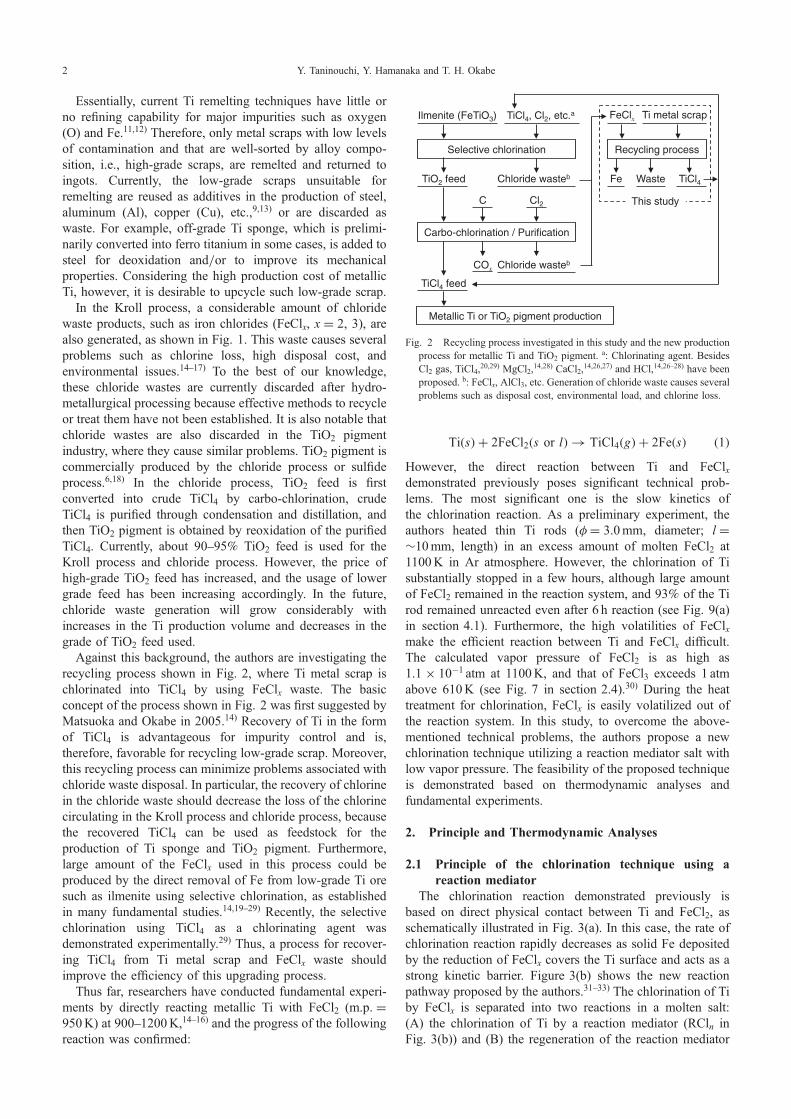
Against this background, the authors are investigating therecycling process shown in Fig. 2, where Ti metal scrap ischlorinated into TiCl4 by using FeClx waste. The basicconcept of the process shown in Fig. 2 was first suggested byMatsuoka and Okabe in 2005.14) Recovery of Ti in the formof TiCl4 is advantageous for impurity control and is,therefore, favorable for recycling low-grade scrap. Moreover,this recycling process can minimize problems associated withchloride waste disposal. In particular, the recovery of chlorinein the chloride waste should decrease the loss of the chlorinecirculating in the Kroll process and chloride process, becausethe recovered TiCl4 can be used as feedstock for theproduction of Ti sponge and TiO2 pigment. Furthermore,large amount of the FeClx used in this process could beproduced by the direct removal of Fe from low-grade Ti oresuch as ilmenite using selective chlorination, as establishedin many fundamental studies.14,1929) Recently, the selectivechlorination using TiCl4 as a chlorinating agent wasdemonstrated experimentally.29) Thus, a process for recover-ing TiCl4 from Ti metal scrap and FeClx waste shouldimprove the efficiency of this upgrading process.
Thus far, researchers have conducted fundamental experi-ments by directly reacting metallic Ti with FeCl2 (m.p. =950K) at 9001200K,1416) and the progress of the followingreaction was confirmed:
TiðsÞ þ 2FeCl2ðs or lÞ ! TiCl4ðgÞ þ 2FeðsÞ ð1ÞHowever, the direct reaction between Ti and FeClxdemonstrated previously poses significant technical prob-lems. The most significant one is the slow kinetics ofthe chlorination reaction. As a preliminary experiment, theauthors heated thin Ti rods (º = 3.0mm, diameter; l =³10mm, length) in an excess amount of molten FeCl2 at1100K in Ar atmosphere. However, the chlorination of Tisubstantially stopped in a few hours, although large amountof FeCl2 remained in the reaction system, and 93% of the Tirod remained unreacted even after 6 h reaction (see Fig. 9(a)in section 4.1). Furthermore, the high volatilities of FeClxmake the efficient reaction between Ti and FeClx difficult.The calculated vapor pressure of FeCl2 is as high as1.1 © 10¹1 atm at 1100K, and that of FeCl3 exceeds 1 atmabove 610K (see Fig. 7 in section 2.4).30) During the heattreatment for chlorination, FeClx is easily volatilized out ofthe reaction system. In this study, to overcome the above-mentioned technical problems, the authors propose a newchlorination technique utilizing a reaction mediator salt withlow vapor pressure. The feasibility of the proposed techniqueis demonstrated based on thermodynamic analyses andfundamental experiments.
2. Principle and Thermodynamic Analyses
2.1 Principle of the chlorination technique using areaction mediator
The chlorination reaction demonstrated previously isbased on direct physical contact between Ti and FeCl2, asschematically illustrated in Fig. 3(a). In this case, the rate ofchlorination reaction rapidly decreases as solid Fe depositedby the reduction of FeClx covers the Ti surface and acts as astrong kinetic barrier. Figure 3(b) shows the new reactionpathway proposed by the authors.3133) The chlorination of Tiby FeClx is separated into two reactions in a molten salt:(A) the chlorination of Ti by a reaction mediator (RCln inFig. 3(b)) and (B) the regeneration of the reaction mediator
Ilmenite (FeTiO3) TiCl4, Cl2, etc.a
Selective chlorination
TiO2 feed
Carbo-chlorination / Purification
Metallic Ti or TiO2 pigment production
Chloride wasteb
FeClx
Recycling process
Ti metal scrap
Cl2C
TiCl4 feed
COx Chloride wasteb
Fe TiCl4Waste
This study
Fig. 2 Recycling process investigated in this study and the new productionprocess for metallic Ti and TiO2 pigment. a: Chlorinating agent. BesidesCl2 gas, TiCl4,20,29) MgCl2,14,28) CaCl2,14,26,27) and HCl,14,2628) have beenproposed. b: FeClx, AlCl3, etc. Generation of chloride waste causes severalproblems such as disposal cost, environmental load, and chlorine loss.
Y. Taninouchi, Y. Hamanaka and T. H. Okabe2

by FeClx. TiCl4 is poorly soluble in molten salt.3436) Thus,the TiCl4 produced in reaction (A) should diffuse into a gasphase. The reaction mediator is reduced into its subchloride(RCln¹¤ in Fig. 3(b)) by reaction (A). However, the producedsubchloride is soluble in molten salt and does not cover thesurface of Ti as a solid product. Therefore, the chlorinationreaction (A) is expected to proceed continuously and quickly.In reaction (B), the subchloride of the reaction mediator ischlorinated by FeClx in the molten salt to regenerate thereaction mediator, and solid Fe is obtained as a by-product.
The proposed technique is favorable for suppressing thevolatilization of FeClx from the reaction system. This isbecause the activity of FeClx is reduced by dissolution in amolten salt. Furthermore, the reaction temperature may bedecreased by using an appropriate molten salt as the reactionsystem. For these reasons, by alternating reactions (A) and(B), TiCl4 is expected to be recovered effectively from Timetal scrap and chloride waste.
2.2 Thermodynamics of lanthanoid chloridesTo find metal chlorides that are suitable as reaction
mediators, different lanthanoid chlorides (LnClx, Ln: lantha-noid element, x = 2, 3) were examined in this study.Lanthanoid elements are usually present as trivalent ionsin their compounds, although some are known to formdichlorides under certain conditions.37,38) In 1998, Udaet al.39,40) reported the magnesiothermic reduction of Ti byDyCl2 in molten salt as a reaction mediator. However, to thebest of our knowledge, chlorination of metallic Ti utilizing areaction mediator salt has not been reported.
Figure 4 shows the chemical potentials of chlorine, �®Cl2
(¼ RT lnpCl2 ), corresponding to Ln/LnCl2 and LnCl2/LnCl3equilibria at 1100K, which were calculated using thermody-namic data available in the literature.30,41) In Fig. 4, thecalculated �®Cl2 values corresponding to Ti/TiCl2, TiCl2/TiCl3, TiCl3/TiCl4, Fe/FeCl2, FeCl2/FeCl3, and Mg/MgCl2equilibria30) are also indicated by dotted lines.
Pure LnCl2 can be present as a stable phase at 1100Kwhen the �®Cl2 for Ln/LnCl2 equilibrium is more negativethan that for LnCl2/LnCl3 equilibrium in Fig. 4. From theviewpoint of equilibrium, LnCl3 can chlorinate (or oxidize)Ti into TiCl4 when the �®Cl2 for LnCl2/LnCl3 equilibrium ismore positive than that for TiCl3/TiCl4 equilibrium. Fur-thermore, when the �®Cl2 for LnCl2/LnCl3 equilibrium ismore negative than those for Fe/FeCl2 and FeCl2/FeCl3equilibria, LnCl2 can be chlorinated (or oxidized) into LnCl3by FeClx. According to the simplified thermodynamiccalculation, it is expected that samarium trichloride (SmCl3,m.p. = 950K) can act as a reaction mediator.
2.3 Thermodynamics of the Sm-Ti-Cl systemThe feasibility of the chlorination of Ti by SmCl3, i.e.,
reaction (A) in Figure 3(b), is further discussed in terms ofthe chemical potential diagram for the Sm-Ti-Cl systemshown in Fig. 5. The calculation was carried out at 1100Kusing thermodynamic data from the literature.30) The activityof all chemical species was assumed to be unity. Intermetalliccompounds are not present in the Sm-Ti system, and themutual solubility of Sm and Ti is negligibly small at1100K.42) As far as the authors know, the double salts (orcomplex chloride compounds) of SmClx and TiClx have notbeen reported.
In Fig. 5, the most stable phases are shown as faces, andthe intersections between faces represent the phase equilibria.Figure 5 clearly shows that Ti cannot coexist with SmCl3 at1100K, and SmCl3 equilibrates with TiCl4 and SmCl2 atpotential point ¡. This means that when a sufficient amountof SmCl3 exists in the reaction system, Ti is chlorinated intoTiCl4 gas according to the following reaction
TiðsÞ þ 4SmCl3ðlÞ ! TiCl4ðgÞ þ 4SmCl2ðsÞ ð2Þ�G�
r,ð2Þ ¼ �140 kJ at 1100K
�H�r,ð2Þ ¼ �137 kJ at 1100K;
Ti
TiCl4
FeClx
Fe
(Scrap) (Chloride waste)
RCln
RCln-δ
in molten salt
physical contact
Ti
TiCl4
(Scrap)
FeClx
Fe
(Chloride waste)
(a)
(b)
Reaction (A) Reaction (B)
Fig. 3 Reaction pathways for chlorinating Ti in metal scraps by utilizingFeClx chloride waste. (a) Chlorination technique reported previously1416)
based on the direct physical contact between Ti and FeClx. DepositedFe covers the surface of Ti and acts as a strong kinetic barrier.(b) Chlorination technique proposed in this paper. In molten salt, Ti ischlorinated into TiCl4 gas by reacting with a reaction mediator (RCln)(reaction (A)), and then the reaction mediator is regenerated from itssubchloride by FeClx (reaction (B)).3133) Chlorination of Ti proceedssmoothly because the Fe deposition on the Ti surface is prevented.
-1000
-800
-600
-400
-200
0
Cl 2
T = 1100 K
TiCl3/TiCl
4 eq.
TiCl2/TiCl
3 eq.
Mg/MgCl2 eq.
Ti/TiCl2 eq.
Fe/FeCl2 eq.
SmPm
NdPr
Ce
Ref. 41) Ln/LnCl2 eq.
LnCl2/LnCl3 eq.
Ref. 30) Ln/LnCl
2 eq.
LnCl2/LnCl
3 eq.C
hem
ical
pot
entia
l of c
hlor
ine,
Δμ
/
kJ·m
ol-1
Element
LuLaYb
TmEr
HoDy
Eu TbGd
FeCl2/FeCl
3 eq.
Fig. 4 Calculated chemical potentials of chlorine corresponding to the Ln/LnCl2 and LnCl2/LnCl3 equilibria at 1100K.30,41) Chlorine potentialscorresponding to the Ti/TiCl2, TiCl2/TiCl3, TiCl3/TiCl4, Fe/FeCl2,FeCl2/FeCl3, and Mg/MgCl2 equilibria30) are also indicated by dottedlines.
Reaction-Mediator-Based Chlorination for the Recycling of Titanium Metal Scrap Utilizing Chloride Waste 3

and the reaction terminates at potential point ¡. The meltingpoint of SmCl2 is 1132K, and its enthalpy of fusion, �H�
fus,is 24 kJ·mol¹1.41) The Gibbs energy change of the followingreaction is small positive value:
SmCl2ðsÞ ! SmCl2ðlÞ ð3Þ�G�
r,ð3Þ ¼ 0:68 kJ at 1100K
In Fig. 5, the effects of molten salt solvents, such asdecreases in activities of some chlorides upon dissolution,are not considered. However, the following chlorinationreaction is expected to proceed in the molten salt system at1100K:
TiðsÞ þ 4SmCl3ðl, in molten saltÞ! TiCl4ðgÞ þ 4SmCl2ðl, in molten saltÞ ð4Þ
2.4 Thermodynamics of the Sm-Fe-Cl systemTo further discuss the regeneration of SmCl3 by FeClx, i.e.,
reaction (B) in Fig. 3(b), the chemical potential diagram forthe Sm-Fe-Cl system was described. Figure 6 shows thediagram for the Sm-Fe-Cl system at 1100K calculated usingthe reported thermodynamic data.30,43) Potential points ¢ and£ represent the SmCl3/Fe/FeCl2 and SmCl3/FeCl2/FeCl3equilibrium states, respectively. It is clear that FeClx coexistswith not SmCl2 but SmCl3. This means that SmCl2 can bechlorinated into SmCl3 by reacting with FeClx as follows:
2SmCl2ðsÞ þ FeCl2ðlÞ ! 2SmCl3ðlÞ þ FeðsÞ ð5Þ�G�
r,ð5Þ ¼ �32:9 kJ at 1100K
�H�r,ð5Þ ¼ �23:8 kJ at 1100K
2SmCl2ðsÞ þ FeCl3ðgÞ ! 2SmCl3ðlÞ þ FeCl2ðlÞ ð6Þ�G�
r,ð6Þ ¼ �227 kJ at 1100K
�H�r,ð6Þ ¼ �339 kJ at 1100K
As mentioned in the previous section, the Gibbs energy offusion of SmCl2 is 0.68 kJ·mol¹1 at 1100K. Consequently,in the molten salt system at 1100K, SmCl2 is poten-tially regenerated into SmCl3 according to the followingreactions:
2SmCl2ðl, in molten saltÞ þ FeCl2ðl, in molten saltÞ! 2SmCl3ðl, in molten saltÞ þ FeðsÞ ð7Þ
2SmCl2ðl, in molten saltÞ þ FeCl3ðl, in molten saltÞ! 2SmCl3ðl, in molten saltÞþ FeCl2ðl, in molten saltÞ ð8Þ
2.5 Vapor pressures of metal chloridesFigure 7 shows the calculated vapor pressures of metal
chlorides as functions of reciprocal temperature. The totalvapor pressures of the monomer and dimer are plotted forSmCl3, FeCl2, and FeCl3. The vapor pressures of SmClx wereevaluated using the thermodynamic data summarized byChervonnyi.41) The vapor pressures of SmCl2 and SmCl3are 7.6 © 10¹7 and 4.9 © 10¹5 atm, respectively, at 1100K,which are both considerably lower than those of TiCl4 andFeClx. Thus, the reaction mediator and its subchloride are notvolatilized from the molten salt during the chlorinationreactions, which is advantageous for the use of SmCl3 as areaction mediator dissolved in molten salt.
3. Experimental
3.1 MaterialsFundamental experiments were carried out to demonstrate
the feasibility of the proposed chlorination technique utilizingSmCl3 as a reaction mediator. MgCl2 (m.p. = 987K) wasselected as the molten salt solvent because it is unreactivewith Ti, FeClx, and SmClx, as evidenced by the thermody-namic calculation shown in Fig. 4, and because it is availableas a by-product during titanium smelting, as shown in Fig. 1.
Table 1 lists the starting materials used in this study.Prior to the experiments, the MgCl2-SmCl3 mixed salt wasprepared by melting a mixture of MgCl2 and SmCl3 reagentsin a molar ratio of about 1 : 1. This mixture was loaded ina carbon crucible, vacuum dried at 473K for 12 h, andimmediately heated at 1100K for 0.5 h under a high-purityAr atmosphere (>99.9995%). The obtained mixed salt was
-60
-40
-20
0
-60
-40
-20
0
0-20
-40-60
α
TiCl3(s)
TiCl4(g)
Cl2(g)
Ti(s)
SmCl2(s)
Sm(s)
SmCl3(l)
TiCl2(s)
log
pC
l (a
tm)
log a Smlog aTi
T = 1100 K2
Fig. 5 Chemical potential diagram for the Fe-Ti-Cl system at 1100K.30)
Ti(s) does not coexist with SmCl3(l). SmCl3(l) equilibrates with SmCl2(s)and TiCl4(g) at potential point ¡.
-60
-40
-20
0
-60
-40
-20
0
0-20
-40-60Fe
2Sm(s)
Sm0.77
Fe0.23
(l)
FeCl3(g)
Fe17
Sm2(s)
Cl2(g)
Fe(s)
SmCl2(s)
Sm(s)
SmCl3(l)
FeCl2(l)
log
pC
l (a
tm)
log a Smlog a
Fe
T = 1100 K
2
γ
Fe2Sm(s)
β
Fig. 6 Chemical potential diagram for the Sm-Fe-Cl system at 1100K.30,43)
SmCl2(s) does not coexist with both FeCl2(l) and FeCl3(g). FeCl2(l)equilibrates with Fe(s) and SmCl3(l) at potential point ¢, and FeCl3(g)equilibrates with FeCl2(l) and SmCl3(l) at the potential point £.
Y. Taninouchi, Y. Hamanaka and T. H. Okabe4

removed from the crucible and then pulverized in an agatemortar (see Fig. 9(b) in section 4.1). To avoid the adsorptionof water from ambient air, the weight measurements of thetwo reagents and the pulverization of the obtained salt werecarried out inside a glove box under a high-purity N2
atmosphere. The composition of the synthesized MgCl2-SmCl3 mixed salt was regarded as MgCl2-50mol% SmCl3based on the mass of the melted reagents.
3.2 Chlorination of Ti by SmCl3 reaction mediator inmolten salt
The experimental apparatus used for the chlorinationreactions is shown in Fig. 8(a). The Ti rod (0.389 g, weight;º = 3.0mm, diameter; l = 12mm, length) and the MgCl2-SmCl3 mixed salt (17.18 g, white powder) were loaded in thecarbon crucible (º = 24mm, I.D.; d = 70mm, depth) insidethe glove box. The molar ratio of Ti, SmCl3, and MgCl2 inthe crucible was 1 : 6 : 6 based on the masses of the loadedsamples. This means that 1.5 times more SmCl3 is loadedthan the stoichiometric amount for reaction (4). The carboncrucible containing the samples was positioned in a verticalgas-tight reaction chamber consisting of a quartz tube
(º = 41mm, I.D.; l = 450mm, length) and a borosilicateglass unit (º = 41mm, I.D.; l = 120mm, length). After that,the samples were dried under vacuum at 473K for more than12 h.
Before the chlorination experiment was started, the insideof the reaction chamber was replaced by high-purity Ar gas.Then, the reaction chamber was introduced into a vertical
Table 1 Materials used in this study.
Material FormPurity(mass%)
Supplier
TiRod,º3.0mm
99.5 The Nilaco Corporation
SmCl3 Powder 99.9 Strem Chemicals, Inc.
FeCl2 Powder 99.9 Kojundo Chemical Laboratory Co., Ltd.
MgCl2 Flake ²97.0* Wako Pure Chemical Industries, Ltd.
*: Major impurity is adsorbed water.
1.0 1.5 2.0 2.5 3.0-10
-8
-6
-4
-2
0
SmCl3+(SmCl
3)2
SmCl2
MgCl2
FeCl2+(FeCl
2)2
TiCl2
TiCl3
TiCl4
Vap
or p
ress
ure,
log
p i (a
tm)
Reciprocal temperature, 1000⋅T -1 / K-1
m.p.
FeCl3+(FeCl
3)2
1200 800 400Temperature, T / K
Fig. 7 Vapor pressures of metal chlorides as functions of reciprocaltemperature.30,41) Open circles indicate the melting points. SmClx showsvapor pressures considerably lower than those of TiCl4 and FeClx.
Quartz rod
Mo cap with holes
Carbon crucible (φ = 24 mm, I.D.;d = 70 mm, depth)containing samples
Ti sponge
Quartz tube(φ = 41 mm, I.D.;l = 450 mm, length)
Mo wire
Ar gas inlet /Vacuum
Viton plug
Electric furnace
Ar gas outlet
Dis
tanc
e fr
om th
e bo
ttom
of q
uart
z tu
be, y
/ m
m
010
020
030
040
0
(a)
500
Borosilicate glass unit(φ = 41 mm, I.D.;l = 120 mm, length)
Empty Water
Trap bottles
400 600 800 1000 12000
100
200
300
400
500
600
Position of gas inlet / outlet
Dis
tanc
e fr
om th
e bo
ttom
of q
uart
z tu
be, y
/ m
m
Temperature, T / K
Position of carbon crucible
(b)
Fig. 8 (a) Schematic illustration of the apparatus for the chlorination ofthe Ti rod and the regeneration of the reaction mediator. The verticalreaction chamber consists of a quartz tube and a borosilicate glass unit.(b) Temperature distribution in the reaction chamber when the samples areheated to 1100K. TiCl4 gas generated from the crucible should moveupward according to the temperature gradient and then be delivered to thetrap bottle by an Ar flow.
Reaction-Mediator-Based Chlorination for the Recycling of Titanium Metal Scrap Utilizing Chloride Waste 5

furnace at an elevated temperature to keep the samples inthe crucible at 1100K for 1 h under an Ar atmosphere. Thetemperature distribution in the reaction chamber is shown inFig. 8(b). During the heat treatment, high-purity Ar gas wasflowed at 100ml·min¹1 through the upper part of the reactionchamber. The TiCl4 gas generated from the crucible wasexpected to diffuse upward following the temperaturegradient and then be carried to the outlet by the Ar current.The outlet gas was bubbled into deionized water before beingdischarged. After the heat treatment, the gas flow wasstopped. Then, the reaction chamber was subsequentlyremoved from the furnace and cooled. The reaction productin the carbon crucible, which is called salt-1 in this paper,was collected and crushed inside the glove box.
3.3 Regeneration of SmCl3 reaction mediator by react-ing with FeCl2
A portion of salt-1 (9.162 g) obtained in the previousexperiment was mixed with FeCl2 (2.752 g) and then reactedat 1100K for 1 h under an Ar atmosphere. Given that theTi rod was completely chlorinated by reaction (4) in theprevious experiment, the composition of salt-1 is estimated tobe MgCl2-33mol%SmCl2-17mol%SmCl3. If this estimationis correct, the samples in carbon crucible contain SmCl2 andFeCl2 in a molar ratio of 1 : 1.
The mixture of salt-1 and FeCl2 was loaded in the carboncrucible inside the glove box and then placed in the reactionchamber shown in Fig. 8(a). After vacuum drying at 473K,heat treatment at 1100K for 1 h was carried out using thesame procedure described in the previous section. In thisstudy, the reaction product collected from the crucible iscalled salt-2. A portion of the obtained salt-2 was subjected toleaching. In this leaching process, the salt-2 was immersed inethanol and then in 50 vol% acetic acid to remove salts suchas MgCl2. The leaching residue was rinsed with distilledwater, ethanol, and then acetone before it was dried in air.
3.4 AnalysesPhase identification was carried out by means of X-ray
diffraction analysis (XRD analysis: Rigaku Co., Ltd., RINT2500, Cu-K¡ radiation). To avoid reaction with the moisturein ambient air, the salt-1 and salt-2 samples were coveredwith a polyimide film in the glove box before XRD analysis.The chemical compositions of the obtained samples wereanalyzed using X-ray fluorescence spectroscopy (XRF: JEOLCo., Ltd., JSX-3100RII) and inductively coupled plasma-atomic emission spectrometry (ICP-AES: SII NanoTechnol-ogy Inc., SPS3520UV). In addition, the pH of the waterthrough which the outlet gas was measured using a pH meter(Horiba D-54) after the chlorination experiment with the Tirod.
4. Results and Discussion
4.1 Chlorination of Ti by SmCl3 reaction mediator inmolten salt
As mentioned in the introduction, most of the Ti rodremained unreacted when it was heated with an excess ofFeCl2 at 1100K (Fig. 9(a)) because the deposited Fecompletely covered the Ti surface and acted as a strong
kinetic barrier. Meanwhile, when heated in the MgCl2-SmCl3molten salt at 1100K for 1 h, the Ti rod completelydisappeared, and only a reaction product with a violet color(salt-1) was recovered from the crucible as shown inFig. 9(c). In Fig. 10, the XRD pattern of salt-1 is shownwith that of the MgCl2-SmCl3 mixed salt. Salt-1 consisted ofMgCl2, Sm3Cl7, and a small amount of SmCl3; diffractionpeaks of Ti were not observed. Figure 11 shows the reportedphase diagram of the SmCl3-SmCl2 system.44) If the Ti rodwas completely chlorinated into TiCl4 according to reaction(4), the molar ratio of SmCl3 to SmCl2 in molten salt wouldbe 1 : 2 based on the mass of feed materials. As shown inFig. 11, solid Sm3Cl7 is a double salt of SmCl3 and SmCl2 ina molar ratio of 1 : 2 and is stable below 899K. Thus, thepresence of Sm3Cl7 in the salt-1 clearly indicates that the Tirod was chlorinated by SmCl3 and that SmCl2 was generatedin the molten salt at 1100K.
10 mm
(a)
(b)
(c)
(d)
10 mm
10 mm
10 mm
Fig. 9 (a) Photograph of the Ti rod immersed in molten FeCl2 at 1100K for6 h. Unreacted FeCl2 was removed by rinsing with distilled water. Thesurface of the obtained Ti rod was rigidly covered by the deposited Fe,and most part of the Ti rod remained unreacted. (b) Photograph of theMgCl2-SmCl3 mixed salt. (c) Photograph of salt-1. The Ti rod completelydisappeared because the SmCl3 reaction mediator in the molten saltchlorinated the metallic Ti without a strong kinetic barrier. (d) Photographof salt-2. The SmCl3 reaction mediator was regenerated by FeCl2. Salt-2contained metallic Fe, as evidenced in Fig. 12.
Y. Taninouchi, Y. Hamanaka and T. H. Okabe6

During the heat treatment, evolution of white smoke in thewater-containing trap bottle shown in Fig. 8(a) was observed.The pH of the water in trap bottle decreased to 1.6 during thechlorination experiment. As shown in Fig. 7, TiCl4 is highlyvolatile, with a vapor pressure exceeding 10¹2 atm even atroom temperature. The evolution of white smoke and thedecrease in pH of the outlet-gas-bubbled water indicate thatTiCl4 gas was generated in the carbon crucible, transportedinto the trap bottle, and then hydrolyzed by the followingreaction: TiCl4 + 2H2O ¼ TiO2 + 4HCl.
The results obtained in this chlorination experimentindicate that Ti can be smoothly chlorinated into TiCl4 gasby SmCl3 in molten salt through chlorination reaction (4).However, it should be noted that not all the Ti rod samplewas volatilized as TiCl4 from the molten salt. Table 2summarizes the masses and compositions of the samples inthe carbon crucible before and after the chlorination experi-ment. ICP-AES revealed that salt-1 contains 1.28mass% Ti.This means that 44% of the Ti rod sample was volatized asTiCl4 or related volatile compounds such as TiCl3, and therest remained in salt-1. The authors speculate that the residualTi forms a subchloride as a transient species during thechlorination into TiCl4 or forms oxides by reacting withoxygen contamination in the molten salt at 1100K. However,the chemical state of the residual Ti in molten salt and
the detailed mechanism of this phenomenon are still underinvestigation.
4.2 Regeneration of SmCl3 reaction mediator by react-ing with FeCl2
Salt-2, which was obtained by reacting salt-1 with FeCl2 at1100K for 1 h, was gray in color (Fig. 9(d)) and attached to amagnet. Figure 10(d) shows the XRD pattern of salt-2. Themajor diffraction peaks are explained by MgCl2 and SmCl3.A photograph and XRD pattern of the leaching residue ofsalt-2 are shown in Fig. 12. The leaching residue of salt-2was dark gray and identified as Fe. As described in theprevious section, salt-1 forms MgCl3-SmCl3-SmCl2 moltensalt at 1100K. The XRD analyses indicate that during theregeneration experiment at 1100K, SmCl3 and Fe wereformed by the reaction of SmCl2 with FeCl2 in the moltensalt. Thus, it is concluded that the SmCl3 reaction mediator inmolten MgCl2 can be regenerated by FeCl2 according toregeneration reaction (7).
Together, the above experimental results demonstrate thatSmCl3 in molten MgCl2 can smoothly chlorinate Ti intoTiCl4 gas and that the SmCl2 generated in molten salt can be
10 20 30 40 50 60 70
(PDF#44-0905)
(PDF#06-0696)
(PDF#12-0789)
(PDF#37-0774)
(d) Salt-2
(c) Salt-1
(b) MgCl2−SmCl
3
mixed salt
(a) Backgound
MgCl2
SmCl3
Sm3Cl
7
Fe
Inte
nsity
, I (
a.u.
)
Angle, 2θ / degree (Cu-Kα)
Fig. 10 XRD patterns of (a) polyimide film (background profile), (b) theMgCl2-SmCl3 mixed salt, (c) salt-1 obtained from the chlorination of theTi rod sample, and (d) salt-2 obtained from the regeneration of the SmCl3reaction mediator.
Tem
pera
ture
, T /
K Liquid
SmCl3 SmCl2SmCl2 content, x (mol%)SmCl2
0 20 40 60 80 100
954 K
700
800
900
1000
1100
1200
42%
1131 K
SmCl3 + Sm3Cl7
1:2
4:9
1:4
αβ
906 K
848 K
1043 K
Expected composition changeduring the chlorination of the Ti rod.
Fig. 11 Phase diagram of SmCl3-SmCl2 pseudo-binary system.44) Theopen circle indicates the estimated molar ratio of SmCl2 to SmCl3 in salt-1, which is evaluated based on the mass of the feed materials, assumingthat the Ti rod is completely chlorinated into TiCl4 according to reaction(4).
Table 2 Mass and composition of the samples in the carbon crucible beforeand after the chlorination of the Ti rod.
Mass,w/g
Composition of element i,Ci (mass%)
Ti Sm Mg Cl
Samples in the crucible beforethe chlorination experiment(mixture of the Ti rod and theMgCl2-SmCl3 mixed salt)
17.57 2.21*1 41.79*1 6.75*1 49.25*1
Samples in the crucible after thechlorination experiment (salt-1)
16.92 1.28*2 47.20*2 5.96*2 45.56*3
*1: Calculated based on the mass of feed materials.*2: Determined by ICPAES.*3: CCl = 100 ¹ (CTi + CSm + CMg).
Reaction-Mediator-Based Chlorination for the Recycling of Titanium Metal Scrap Utilizing Chloride Waste 7

regenerated into SmCl3 by reaction with FeCl2. Hence, thisnovel chlorination technique for more effectively recycling Timetal scrap and chloride waste (Fig. 3(b)) by utilizing SmCl3as a reaction mediator is feasible. To further improve theproposed chlorination technique, it is essential to investigatethe behavior of impurities such as O, Al, and V. Furthermore,the search for a more economical reaction mediator is alsoimportant.
5. Conclusions
To establish an efficient recycling process for both Ti metalscrap and FeClx waste, the authors devised a novel Tichlorination technique and demonstrated its feasibility. In thistechnique, a metal chloride dissolved in a molten salt solventmediates the chlorination reaction between Ti and FeClx. Thisallows TiCl4 to be extracted continuously, as metallic Ti ischlorinated by a reaction mediator and the consumed reactionmediator is regenerated by FeClx. Based on thermodynamicconsiderations and fundamental experiments, it was con-firmed that SmCl3 in molten MgCl2 works as a reactionmediator at 1100K. Although this study only establishes thefundamental feasibility of this technique, it can be concludedthat the newly proposed chlorination technique will be usefulfor the development an efficient and environmentally friendlyrecycling process.
Acknowledgement
The authors are grateful to Professors Tetsuya Uda andNaoyuki Hatada, Kyoto University, and Professor Shu
Yamaguchi and Dr. Katsuhiro Nose, The University ofTokyo, for their invaluable discussions. The authors thankMr. Akihiro Yoshimura of the University of Tokyo for hispreliminary study. Furthermore, the authors are grateful toMessrs. Susumu Kosemura, Masanori Yamaguchi, YuichiOno, and Yosuke Inoue, Toho Titanium Co., Ltd., and Mr.Jungshin Kang, The University of Tokyo, for their valuablesuggestions. This work was supported by the Japan Societyfor the Promotion of Science (JSPS) through the Grant-in-Aid for Young Scientists (B) (KAKENHI Grant Number25820375), the Funding Program for Next Generation World-Leading Researchers (NEXT Program), and the Grant-in-Aidfor Scientific Research (S) (KAKENHI Grant Number26220910).
REFERENCES
1) S. Nakamura: Industrial Rare Metals No. 117, (Arumu Pub., Tokyo,Japan, 2001) pp. 6567 (in Japanese).
2) S. Nakamura: Industrial Rare Metals No. 129, (Arumu Pub., Tokyo,Japan, 2013) pp. 6872 (in Japanese).
3) C. Cui, B. Hu, L. Zhao and S. Liu: Mater. Des. 32 (2011) 16841691.4) G. M. Bedinger: Mineral Commodity Summaries: Titanium and
Titanium Dioxide, (U.S. Geological Survey, Washington D.C., USA,2014) pp. 170171.
5) W. Kroll: Trans. Electrochem. Soc. 78 (1940) 3547.6) F. Habashi (ed.): Handbook of Extractive Metallurgy, (VCH Verlags-
gesellschaft mbH, Weinheim, Germany, 1997) Vol. 2, pp. 11291180.7) O. Takeda, T. Uda and T. H. Okabe: Treatise on Process Metallurgy,
Volume 3: Industrial Processes, (Elsevier, London, UK, 2013)Chap. 2.9, pp. 9951069.
8) Y. Marui, T. Kinoshita and K. Takahashi: Honda R&D Tech. Rev. 14(2002) 149156 (in Japanese).
9) T. Suziki and T. Kaneko: The Latest Technological Trend of RareMetals, (CMC Publishing Co. Ltd., Tokyo, Japan, 2012) Chap. 64,pp. 117127 (in Japanese).
10) T. G. Goonan: Flow Studies for Recycling Metal Commodities in theUnited States: U.S. Geological Survey Circular 1196, (U.S. GeologicalSurvey, Washington D.C., USA, 2010) Chap. Y, pp. Y1Y16.
11) X. Lu, T. Hiraki, K. Nakajima, O. Takeda, K. Matsuabe, H.-M. Zhu, S.Nakamura and T. Nagasaka: Sep. Purif. Technol. 89 (2012) 135141.
12) Y. Ito: Titanium Japan 61 (2013) 4851 (in Japanese).13) T. Suzuki: Titanium Japan 57 (2009) 2129 (in Japanese).14) R. Matsuoka and T. H. Okabe: Proc. Symp. on Metallurgical
Technology for Waste Minimization, (134th TMS Annual Meeting,San Francisco, United States, 2005). http://www.okabe.iis.u-tokyo.ac.jp/japanese/for_students/parts/pdf/050218_TMS_proceedings_matsuoka.pdf
15) H. Zheng, R. Matsuoka and T. H. Okabe: Proc. Eur. MetallurgicalConf. (EMC2005), (2005) Vol. 4, pp. 15091518.
16) H. Zheng and T. H. Okabe: J. Alloy. Compd. 461 (2008) 459466.17) T. H. Okabe and J. Kang: The Latest Technological Trend of Rare
Metals, (CMC Publishing Co. Ltd., Tokyo, Japan, 2012) Chap. 61,pp. 8394 (in Japanese).
18) M. Matsunaga: J. Jpn. Soc. Colour Mater. 54 (1981) 680689.19) L. K. Doraiswamy, H. C. Bijawat and M. V. Kunte: Chem. Eng. Prog.
55 (1959) 8088.20) D. F. Othmer and R. Nowak: AIChE J. 18 (1972) 217220.21) A. Fuwa, E. Kimura and S. Fukushima: Metall. Trans. B 9 (1978) 643
652.22) E. Kimura, A. Fuwa and S. Fukushima: Nippon Kogyo Kaishi 95
(1979) 821827 (in Japanese).23) K. I. Rhee and H. Y. Sohn: Metall. Trans. B 21 (1990) 321330.24) K. I. Rhee and H. Y. Sohn: Metall. Trans. B 21 (1990) 331340.25) K. I. Rhee and H. Y. Sohn: Metall. Trans. B 21 (1990) 341347.26) H. Zheng and T. H. Okabe: Proc. 16th Iketani Conf., Masuko
Symposium, Ed. by S. Yamaguchi, (The 16th Iketani ConferenceOrganizing Committee, Japan, 2006) pp. 10051010.
10 20 30 40 50 60 70 80 90
Fe (PDF#06-0696)
Inte
nsity
, I
(a.u
.)
Angle, 2θ / degree (Cu-Kα)
(a)
(b)
2 mm
Fig. 12 (a) Photograph and (b) XRD pattern of the leaching residue of thesalt-2.
Y. Taninouchi, Y. Hamanaka and T. H. Okabe8

27) J. Kang and T. H. Okabe: Metall. Mater. Trans. B 44 (2013) 516527.28) J. Kang and T. H. Okabe: Mater. Trans. 54 (2013) 14441453.29) J. Kang and T. H. Okabe: Mater. Trans. 55 (2014) 591598.30) I. Barin: Thermochemical Data of Pure Substances, 3rd ed., (VCH
Verlagsgesellschaft mbH, Weinheim, Germany, 1995).31) Y. Hamanaka, Y. Taninouchi and T. H. Okabe: Proc. MMIJ Fall
Meeting, (2013) Vol. CD, p. 588. http://www.mmij.or.jp/convention/doc_file.inc.cpx?est=aa20582821f78aa28f976c4127496086 (in Japa-nese).
32) Y. Hamanaka, Y. Taninouchi and T. H. Okabe: CollectedAbstract of the 2014 TMS Annual Meeting & Exhibition,(2014). http://www.programmaster.org/PM/PM.nsf/ApprovedAbstracts/8EDF15581894774C85257B9B005154A5?OpenDocument.
33) Y. Taninouchi, Y. Hamanaka and T. H. Okabe: Proc. MMIJSpring Meeting (2014). http://www.mmij.or.jp/convention/doc_file.inc.cpx?est=96f0688f5fd4f1a4e1328d3fe9b49041 (in Japanese).
34) M. V. Smirnov and V. S. Maksimov: Electrochem. Mol. Sol.Electrolytes 7 (1969) 3741.
35) T. Uda, T. H. Okabe and Y. Waseda: J. Japan Inst. Metals 62 (1998) 7684 (in Japanese).
36) R. O. Suzuki, T. N. Harada, T. Matsunaga, T. N. Deura and K. Ono:
Metall. Mater. Trans. B 30 (1999) 403410.37) G. Czack, I. Flachsbart, H. Hein, E. Koch, I. Kreuzbicher, P. Kuhn, H.
Lehl and U. Vetter: Gmelin Handbook of Inorganic Chemistry Sc, Y,La-Lu Rare Earth Elements Part C4b, 8th ed. (Springer-Verlag, Berlin,Germany, 1982).
38) T. Uda, K. T. Jacob and M. Hirasawa: Science 289 (2000) 23262329.39) T. Uda, T. H. Okabe and Y. Waseda: J. Japan Inst. Metals 62 (1998)
796802 (in Japanese).40) T. H. Okabe, T. Uda and Y. Waseda: Shigen-to-Sozai 114 (1998) 573
579 (in Japanese).41) A. D. Chervonnyi: Handbook on the Physics and Chemistry of Rare
Earths, Vol. 42 (Elsevier B.V., Amsterdam, Nederland, 2012)Chap. 253, pp. 165484.
42) SpringerMaterials®The Landolt-Börnstein Database. Materials Sci-ence International Team MSITμ and N. Kol’chugina: IronSamarium
Titanium (Springer-Verlag, Berlin, Germany, 2009). http://www.springermaterials.com/docs/pdf/978-3-540-70890-2_30.html
43) M. Zinkevich, N. Mattern, A. Handstein and O. Gutfleisch: J. Alloy.Compd. 339 (2002) 118139.
44) D. M. Laptev, V. F. Goryushkin, I. S. Astakhova and G. G. Polyakova:Russ. J. Inorg. Chem. 24 (1979) 730733.
Reaction-Mediator-Based Chlorination for the Recycling of Titanium Metal Scrap Utilizing Chloride Waste 9