reaction wheel configurations for high and middle ... · reaction wheel configurations for high and...
TRANSCRIPT

VOL. 10, NO. 21, NOVEMBER 2015 ISSN 1819-6608
ARPN Journal of Engineering and Applied Sciences
©2006-2015 Asian Research Publishing Network (ARPN). All rights reserved.
www.arpnjournals.com
10034
REACTION WHEEL CONFIGURATIONS FOR HIGH AND MIDDLE
INCLINATION ORBITS
Zuliana Ismail
and Renuganth Varatharajoo
Department of Aerospace Engineering, Universiti Putra Malaysia, Malaysia
E-Mail: [email protected]
ABSTRACT
The purpose of this paper is to identify the low-power Reaction Wheel (RW) configuration for a 3-axis satellite
attitude control at high and middle inclination orbits. All of the proposed RW configurations are evaluated through the
numerical simulations with respect to an identical reference mission. The simulations are tested for two different orbit
positions; first, at a high inclination (e.g., 83°), second, at a middle inclination (e.g., 53°). All configurations are analysed
in terms of their total torques and attitude performances. The stable attitude accuracies (≈0.001°) are achieved in all the configurations either at 83° or 53° inclinations. Results also revealed that the change of orbit inclination slightly influences
the determination of the low-power RW configurations. This research provides a quick summary on a possible low-power
arrangement of reaction wheels onboard a small satellite.
Keywords: reaction wheel, Satellite attitude control, control torque.
INTRODUCTION
Most of the sophisticated satellite missions rely
on the use of Reaction Wheels (RWs) for precision
satellite attitude controls [1]. RWs act as a source of
action-reaction energy to generate the control torques.
When a satellite rotates one way due to the disturbance
torques (i.e., solar pressure, aerodynamic drag, etc.), the
RWs will be counter-rotated to produce the same
magnitude reaction torque in order to correct the attitude.
Practically, a set of two, three or four RWs configuration
with the suitable attitude controllers are employed for a
full 3-axis satellite attitude control as discussed by Kim et
al. [2]. Therefore, the 3-axis satellite attitude control using
the RWs is indeed an important subject of research [3-4].
For a small satellite, it is rather challenging to adopt
multiple RWs due to the power limitations problem. There
are a number of researches which investigate the issue of
minimizing the power consumed by RWs onboard small
satellite such as RWs miniaturization [5-6] and controller
optimization [7]. A torque efficient attitude control system
is indeed desirable in many recent innovative space
systems [8-12]. Basically, the total torque as well as the
power consumed by the RWs can be lowered by
particularly arranging the RWs’ orientation on-board the
satellite[13]. However, the available literature on wheel
configuration issues proves that the results are difficult to
compare and adopt as they were all tested with different
parameters and conditions [14-15]. Moreover, the earlier
study was only focused on a single configuration
optimization without the inclination variations [13]or was
limited to three RWs’ configuration [16]. In contrast, in this work, all the possible RW
configurations for a 3-axis satellite attitude control are
introduced and tested under an identical reference mission
with different inclinations, making them unique in
comparison to all the existing works. This study is done
for two configurations, the first for three RWs and the
second for four RWs. Firstly, the standard mathematical
models of the satellite attitude control system with RWs
are described, whereby the standard PD-type
(proportional-derivative) controller is adopted.
The suitable RW orientation that produces a
minimum total control torque can be identified by
estimating the total torques required to maintain the 3-axis
satellite attitude control. The simulations are performed
for two different inclinations which are the high orbit
inclination (e.g., 83°) and the middle orbit inclination
(e.g., 53°). Note that these inclinations are proposed as
examples to facilitate the analysis herein.
METHODOLOGY
Attitude dynamics and kinematics
Normally, the satellite’s equations of motion are linearized when the Euler’s angles are assumed to be small. According to this work, the satellite’s equations of motion are not linearized in order to ensure the system is
applicable even for the large Euler’s angles. The non-
linear satellite’s dynamic equation with RWs can be written as [2]:
x y z z y wz y wy z
xx
y z x x z wx z wz xy
y
z x y y x wy x wx y
zz
T I I h h
I
T I I h h
I
T I I h h
I
(1)
Assuming that the external torques consist of the
aerodynamic torques and solar torques, thus the total
disturbance torques may be written as:
(2)
where each of them are modelled as the sum of constant
and harmonic quantities as follows:

VOL. 10, NO. 21, NOVEMBER 2015 ISSN 1819-6608
ARPN Journal of Engineering and Applied Sciences
©2006-2015 Asian Research Publishing Network (ARPN). All rights reserved.
www.arpnjournals.com
10035
(3)
For attitude kinematics, quaternion method is
adopted because of its numerical advantages and
avoidance of singularities. Thus, the derivatives of the
Euler parameters can be updated using the kinematics
equation as follows [17].
(4)
where q is an attitude quaternion that represents the
attitude of the satellite relative to the local-vertical-local-
horizontal (LVLH) frame and Ω is the skew symmetric
matrix.
Reaction wheel control strategy
The block diagram of the RW control strategy
with a PD controller is presented in Figure-1.
Figure-1. Block diagram for satellite attitude control using
reaction wheels.
As the command control torques depends on the
quaternion and angular rate errors, the control law can be
represented as [2]:
(5)
where the error quaternion ���� is the quaternion
difference between the reference quaternion �� and the
current quaternion �� . Whereas, �� is the angular rate
error.
From Equation (5), it is found that the system is
based on the second order dynamic system, thus the
equations to find the proportional and derivative gains are � = �� and � = � �� , respectively. These
control gains are the functions of dynamic characteristics,
i.e., the natural frequency � and the damping ratio �.
In addition, the derivation of Euler angles error [�, �, ]� from the attitude quaternion error is as
follows [18].
1 4 2 3
2 2
1 2
4 2 3 1
4 3 1 2
2 2
2 3
2( )arctan
1 2( )
arcsin 2( )
2( )arctan
1 2( )
q q q q
q q
q q q q
q q q q
q q
(6)
From Figure-1, considering that a maximum of
four RWs are installed onboard the satellite, the applied 3-
axis control torque�wfrom the RWs can be calculated as:
(7)
where �w is the RW configuration matrix
and �c is the wheel control torque.
For example, if there are three RWs aligned along
the primary axis of the satellite and a redundant wheel
tilted at equal distances from the others, �w can be
defined as
(8)
In order to determine the magnitudes of wheel control
torque � , the pseudo-inverse of the RW configuration
matrix [�w]− can be multiplied with the commanded
control torques �a obtained in Eq. (5).
(9)
The configuration matrix in Eq. (8) is
representing just one of the possible RW orientations that
can be implemented on-board a satellite. Actually, there
are more possible orientations available without degrading
the 3-axis attitude control. The different configurations of
the RW that are proposed in this study both for three RWs
set and four RWs are summarized in the Figure-2 (a) – (j)
and Figure-3, respectively. Among those configurations,
the suitable RW orientation that consumes a minimum
current can be identified by calculating their total
minimum torques required to maintain the 3-axis satellite
attitude control.
Numerical simulations
In order to simulate the satellite attitude control
performance, a reference mission is proposed as in Tables
1 and 2. All the RWs are assumed to be identical and their
configurations will be simulated using the reference
mission. Thus, the governing equations and the reference
missions’ parameters are implemented in the Matlab
SimulinkTM
codes. Then, numerical treatments are
performed, which allow an assessment of the each
configuration’s merit.

VOL. 10, NO. 21, NOVEMBER 2015 ISSN 1819-6608
ARPN Journal of Engineering and Applied Sciences
©2006-2015 Asian Research Publishing Network (ARPN). All rights reserved.
www.arpnjournals.com
10036
Table-1. Orbit parameters.
Table-2. Satellite specifications.
Figure-2. (a) – (j). Configuration matrix of 3 reaction wheels.
Figure-3. (a) – (h). Configuration matrix of 4 reaction wheels.

VOL. 10, NO. 21, NOVEMBER 2015 ISSN 1819-6608
ARPN Journal of Engineering and Applied Sciences
©2006-2015 Asian Research Publishing Network (ARPN). All rights reserved.
www.arpnjournals.com
10037
RESULTS
Performance analysis
The simulation result pertaining to each
configuration is carefully evaluated in terms of their
torques and attitude performances. The RW configuration
that has a minimum total control torque level is identified
in order to determine a minimum power intake
configuration. The performance analysis for all the test
cases corresponding to three and four RWs for the
simulation at inclinations of 83° and 53° are summarized
in Tables 3 and 4, respectively.
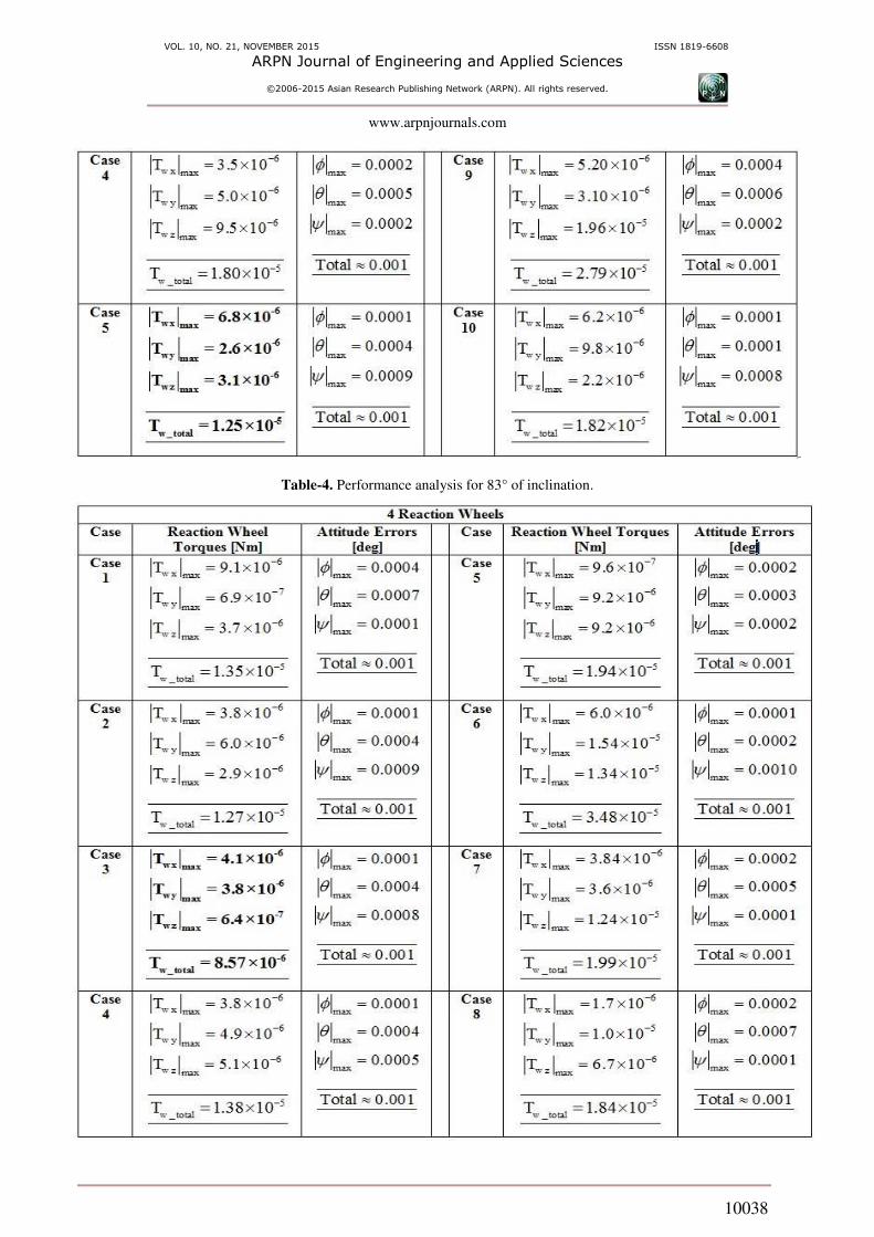
For the three RWs at 83° of inclination, the total
minimum torque is in Case 5, Tw_t tal = . 5 × − Nm,
where one wheel is aligned along x axis and the other two
wheels are tilted; see Figure 2 (e). While, for three RWs at
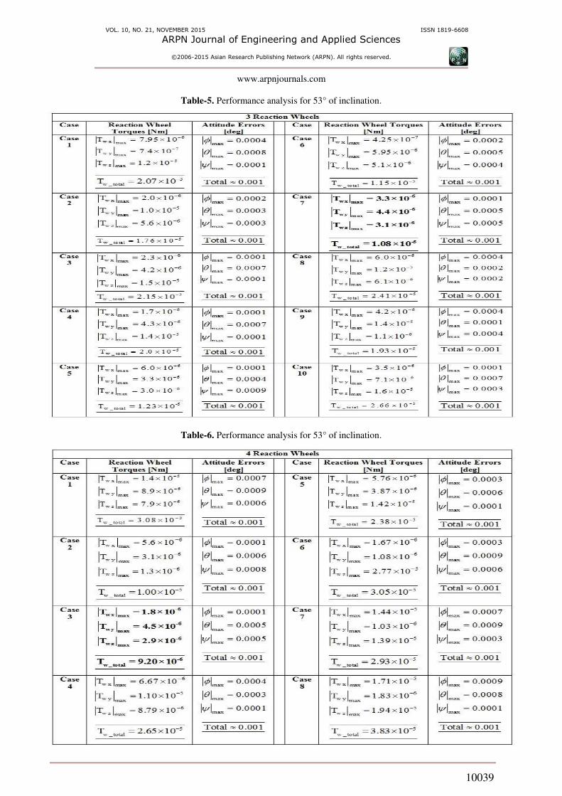
53° of inclination, the total minimum torque is in Case
7Tw_t tal = . × − Nm, where one wheel is aligned
along z axis and the others are tilted; see Figure-2(g).
For the four RWs both at 83° and 53° of
inclination, the total minimum torque is in Case 3, where
two wheels are aligned along x and z axes and the other
two wheels are tilted, see Figure-3 (c). The total minimum
torque for inclination of 83° and 53° are Tw_t tal =.5 × − Nmand Tw_t tal = . × − Nm,
respectively. These minimum torque configurations
correspond to the minimum power intake configurations
as well.
By comparing the results at these two different
inclinations (i.e.; 83° and 53°), the total minimum torque
for four RWs configuration is retained in the same case as
in Case 3. However, the total minimum torque for three
RWs configuration resulting in the different cases,
whereby the best cases are in Case 5 and Case 7 for 83°
and 53° of inclinations, respectively. These results convey
that the change of orbit inclinations, actually, influences
the satellite’s attitude control performances, i.e., the generation of attitude control torques and pointing
accuracies. Looking at the pointing performances, all the
configurations have a similar total attitude pointing
accuracy of about 0.001°. Nevertheless, the best attitude
pointing (<0.001°) is achieved in Case 1 of three RWs at
83° of inclination. However, this configuration
fundamentally inherits a catastrophic failure in the case of
one wheel failure compared to all the other configurations
at 83°; and therefore, it is not a suitable configuration for
satellite missions [17].
Attitude control performances
Indeed, the full 3-axis satellite attitude controls
are achieved in all the test cases; thus, only each case of
the three and four RWs configuration attitude performance
plot is shown for each of 83° and 53° of inclinations.
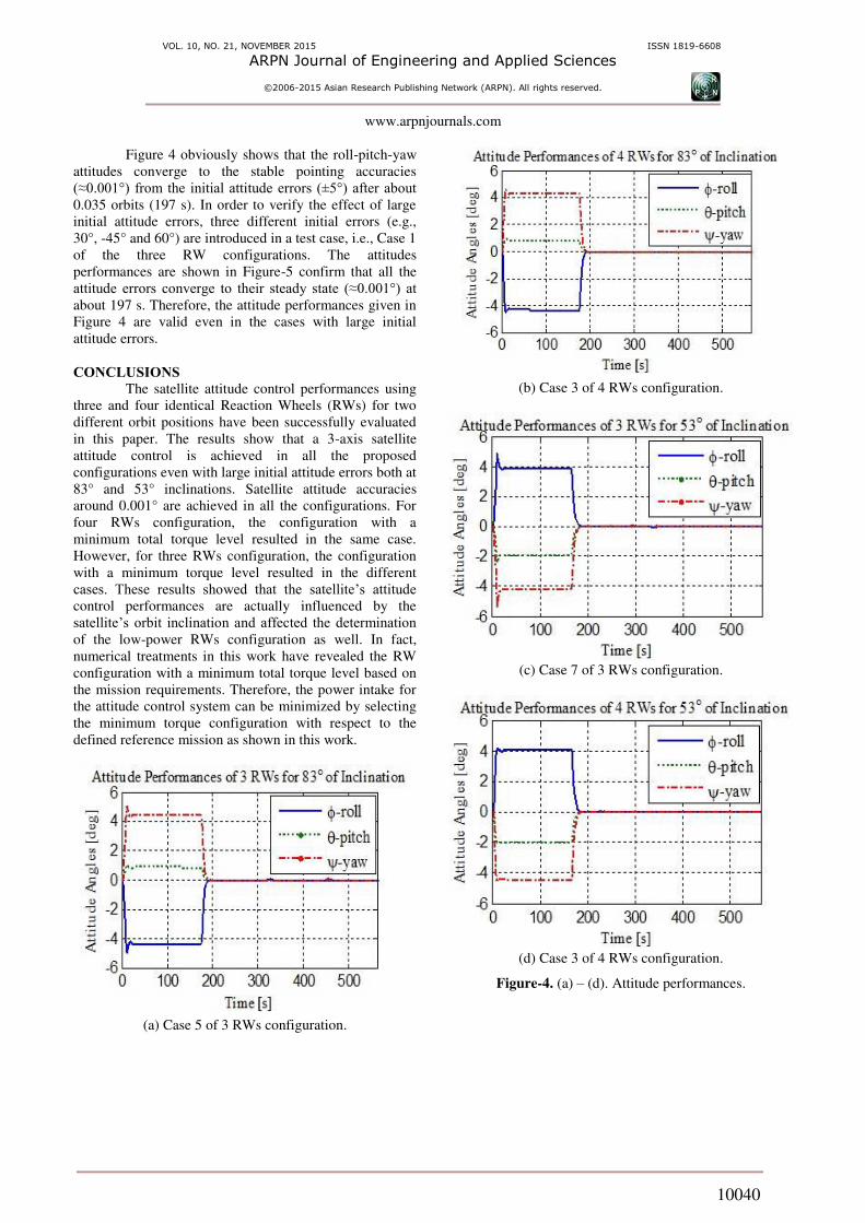
Figures-4 (a)-(b) show the satellite attitude performances
at 83° of inclination for Case 5 of the three RWs
configuration and Case 3 of the four RWs configuration.
Whereas Figures-4 (c)-(d) represent the satellite attitude
performances at 53° of inclination for Case 7 of the three
RWs configuration and Case 3 of the four RWs
configuration.
Table-3. Performance analysis for 83° of inclination.
VOL. 10, NO. 21, NOVEMBER 2015 ISSN 1819-6608
ARPN Journal of Engineering and Applied Sciences
©2006-2015 Asian Research Publishing Network (ARPN). All rights reserved.
www.arpnjournals.com
10038
Table-4. Performance analysis for 83° of inclination.
VOL. 10, NO. 21, NOVEMBER 2015 ISSN 1819-6608
ARPN Journal of Engineering and Applied Sciences
©2006-2015 Asian Research Publishing Network (ARPN). All rights reserved.
www.arpnjournals.com
10039
Table-5. Performance analysis for 53° of inclination.
Table-6. Performance analysis for 53° of inclination.
VOL. 10, NO. 21, NOVEMBER 2015 ISSN 1819-6608
ARPN Journal of Engineering and Applied Sciences
©2006-2015 Asian Research Publishing Network (ARPN). All rights reserved.
www.arpnjournals.com
10040
Figure 4 obviously shows that the roll-pitch-yaw
attitudes converge to the stable pointing accuracies
(≈0.001°) from the initial attitude errors (±5°) after about 0.035 orbits (197 s). In order to verify the effect of large
initial attitude errors, three different initial errors (e.g.,
30°, -45° and 60°) are introduced in a test case, i.e., Case 1
of the three RW configurations. The attitudes
performances are shown in Figure-5 confirm that all the
attitude errors converge to their steady state (≈0.001°) at about 197 s. Therefore, the attitude performances given in
Figure 4 are valid even in the cases with large initial
attitude errors.
CONCLUSIONS
The satellite attitude control performances using
three and four identical Reaction Wheels (RWs) for two
different orbit positions have been successfully evaluated
in this paper. The results show that a 3-axis satellite
attitude control is achieved in all the proposed
configurations even with large initial attitude errors both at
83° and 53° inclinations. Satellite attitude accuracies
around 0.001° are achieved in all the configurations. For
four RWs configuration, the configuration with a
minimum total torque level resulted in the same case.
However, for three RWs configuration, the configuration
with a minimum torque level resulted in the different
cases. These results showed that the satellite’s attitude control performances are actually influenced by the
satellite’s orbit inclination and affected the determination of the low-power RWs configuration as well. In fact,
numerical treatments in this work have revealed the RW
configuration with a minimum total torque level based on
the mission requirements. Therefore, the power intake for
the attitude control system can be minimized by selecting
the minimum torque configuration with respect to the
defined reference mission as shown in this work.
(a) Case 5 of 3 RWs configuration.
(b) Case 3 of 4 RWs configuration.
(c) Case 7 of 3 RWs configuration.
(d) Case 3 of 4 RWs configuration.
Figure-4. (a) – (d). Attitude performances.

VOL. 10, NO. 21, NOVEMBER 2015 ISSN 1819-6608
ARPN Journal of Engineering and Applied Sciences
©2006-2015 Asian Research Publishing Network (ARPN). All rights reserved.
www.arpnjournals.com
10041
Figure-5. Attitude performances for different initial
attitude errors.
REFERENCES
[1] F. F. Mobley, W. E. Radford and L. R. Kennedy.
1996. “MSX attitude determination and control hardware,” Johns Hopkins APL Tech. Dig. (Applied Phys. Lab., Vol. 17, No. 2, pp. 153–159.
[2] B. Kim, H. Lee and S. Choi. 1996. “Three-Axis
Reaction wheel Attitude Control System for Kitsat-3
Microsatellite,” Sp. Technol. Res. Cent., Vol. 16, No.
5–6, pp. 291–296.
[3] S. Ge. 2006. “A Comparative Design of Satellite Attitude Control System with Reaction Wheel,” First NASA/ESA Conf. Adapt. Hardw. Syst., pp. 359–364.
[4] S. S. Nudehi, U. Farooq, A. Alasty and J. Issa. 2008.
“Satellite attitude control using three reaction wheels,” 2008 Am. Control Conf., pp. 4850–4855,
Jun.
[5] Y. Zhang, Y. Postrekhin, K. B. Ma and W.-K. Chu.
2002. “Reaction wheel with HTS bearings for mini-satellite attitude control,” Superconductor Science and
Technology, Vol. 15, No. 5. pp. 823–825.
[6] K. B. Ma, Y. Zhang, Y. Postrekhin and W. K. Chu.
2003. “HTS bearings for space applications: Reaction wheel with low power consumption for mini-
satellites,” in IEEE Transactions on Applied Superconductivity, Vol. 13, No. 2 II, pp. 2275–2278.
[7] S. Zhaowei, G. Yunhai, X. Guodong and H. Ping,
“The combined control algorithm for large-angle
maneuver of HITSAT-1 small satellite,” Acta Astronaut., Vol. 54, No. 7, pp. 463–469.
[8] R. Varatharajoo. 2006. “Onboard errors of the combined energy and attitude control system,” Acta Astronaut., Vol. 58, No. 11, pp. 561–563, Jun.
[9] R. Varatharajoo. 2006. “Operation for the combined energy and attitude control system,” Aircr. Eng. Aerosp. Technol., Vol. 78, No. 6, pp. 495–501.
[10] R. Varatharajoo and F. Nizam. 2004. “Attitude Performance of the Spacecraft Combined Energy and
Attitude Control System,” J. Br. Interplanet. Soc., vol. 57, pp. 237–241.
[11] R. Varatharajoo and T. Ahmad. 2004. “Flywheel energy storage for spacecraft,” Aircr. Eng. Aerosp. Technol., Vol. 76, pp. 384–390.
[12] E. Stoll, S. Jaekel, J. Katz, A. Saenz-Otero and R.
Varatharajoo. 2012. “SPHERES interact-human-
machine interaction aboard the International Space
Station,” J. F. Robot., Vol. 29, No. 4, pp. 554–575.
[13] Z. Ismail and R. Varatharajoo. 2010. “A study of reaction wheel configurations for a 3-axis satellite
attitude control,” Adv. Sp. Res., Vol. 45, No. 6, pp.
750–759, March.
[14] B. Lee, B. Lee, H. Oh, S. Lee and S. Rhee. 2005.
“Time optimal attitude maneuver strategies for the agile spacecraft with reaction wheels and thrusters,” J. Mech. Sci. Technol.
[15] J. Jin, S. Ko and C.-K. Ryoo. 2008. “Fault tolerant control for satellites with four reaction wheels,”
VOL. 10, NO. 21, NOVEMBER 2015 ISSN 1819-6608
ARPN Journal of Engineering and Applied Sciences
©2006-2015 Asian Research Publishing Network (ARPN). All rights reserved.
www.arpnjournals.com
10042
Control Eng. Pract., Vol. 16, No. 10, pp. 1250–1258,
October.
[16] H. B. Hablani. 1994. “Sun-tracking commands and
reaction wheel sizing with configuration
optimization,” J. Guid. Control. Dyn., Vol. 17, No. 4,
pp. 805–814, July.
[17] M. J. Sidi. 1997. Spacecraft dynamics and control: a
practical engineering approach. Vol. 7. Cambridge
university press.
[18] C. J. Van Beusekom, R. Lisowski, J. M. Fulton and C.
Morand. 2003. “Three-axes attitude determination and
control system design for low-cost micro-satellites,” in IEEE Aerospace Conference Proceedings, Vol. 6,
pp. 2615–2628.