reactor, boiler auxiliaries - course 233 steam supply ... library/20042221.pdf · reactor, boiler...
TRANSCRIPT
233.60-1
Reactor, Boiler & Auxiliaries - Course 233
STEAM SUPPLY SYSTEM
I. INTRODUCTION
This section will discuss the turbine steam supplysystem hardware and its functions. To avoid excessiveoverlap with the Turbine and Auxiliaries Courses, the hardware description will be short, the emphasis being on therelationship of the steam side components with the HTsystem rather than with the turbine itself, the latterbeing the emphasis of the turbine courses. The boilerfeedwater system is not discussed here as it is not in thereactor systems USI section.
II. EQUIPMENT DESCRIPTION
(a) Typical Steam Supply System
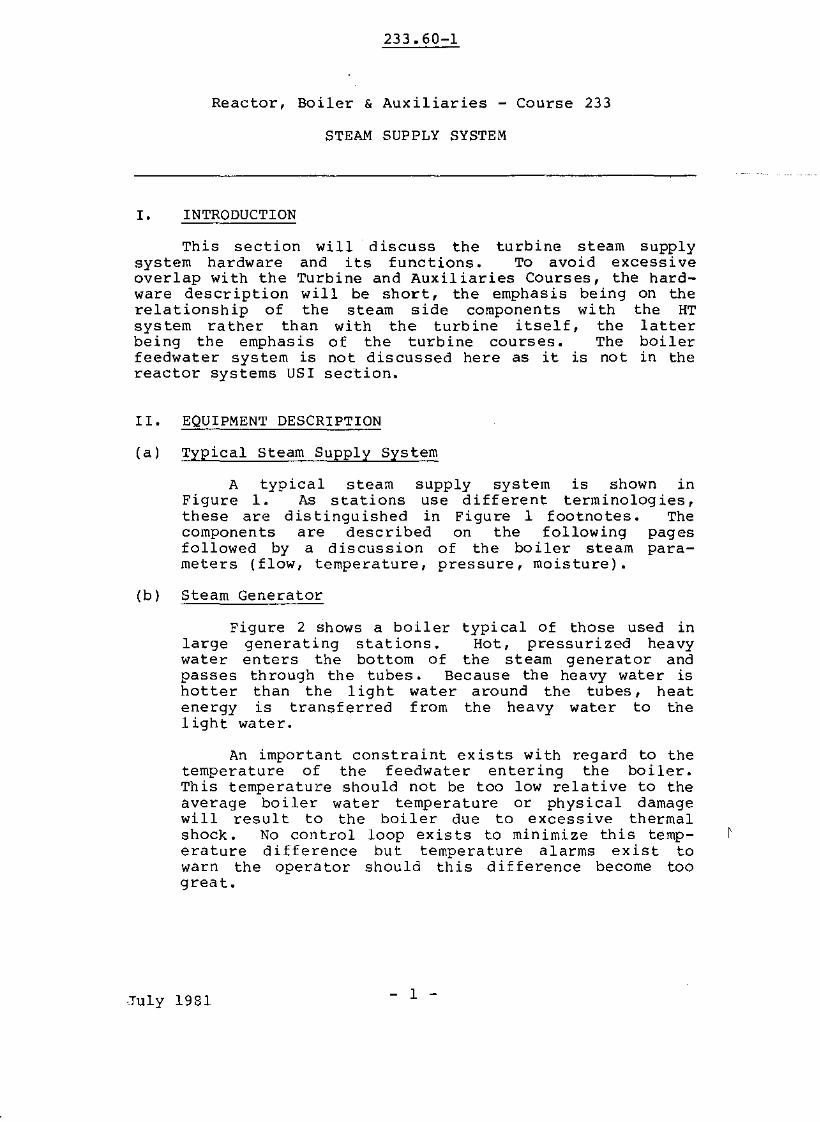
A typical steam supply system is shown inFigure 1. As stations use different terminologies,these are distinguished in Figure 1 footnotes. Thecomponents are described on the following pagesfollowed by a discussion of the boiler steam parameters (flow, temperature, pressure, moisture).
(b) Steam Generator
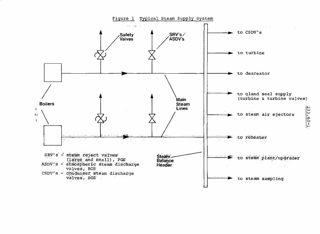
Figure 2 shows a boiler typical of those used inlarge generating stations. Hot, pressurized heavywater enters the bottom of the steam generator andpasses through the tubes. Because the heavy water ishotter than the light water around the tubes, heatenergy is transferred from the heavy water to thelight water.
An important constraint exists with regard to thetemperature of the feedwater entering the boiler.This temperature should not be too low relative to theaverage boiler water temperature or physical damagewill result to the boiler due to excessive thermalshock. No control loop exists to minimize this temperature difference but temperature alarms exist towarn the opera tor should th is difference become toogreat.
,July 1981 - 1 -
B
to gland seal supply(turbine & turb1rte valves)
'"
Figure _1 TY2ical Steam Supply Syste!!!
---"
Safely SRV's//valves / ASDV's
9
/ \Main
oilers SteamLines
\ ® ~. .. . .. ""'.. f-''''-'''.-'-'-10"-• c
SltV1fi' -- ~eatlrieJE;ct val"ves , Steahf~ -.ASDV's - J€~t~~h:ffcS~~~~"di~harge ~~a~;r
valve-s,' BGSCSDV's - cbIi"dens-er Ste'am dis'chargeva-l-ves-, B'GS-
to CSDV's
to turbine
to deareator
to steam air ejectors
to t~hea'ter
to steani' pla~t:/up4rader
to steam sampling
'"ww'"oI,..,

233.60-1
Feedwater enters the boiler near the bottom ofthe tube bundle. The feedwater as it leaves the lastfeed-heater, is still much colder ( 175°C) than thewater in the steam generator, and to reduce thepossibility of thermal shock to a minimum, the watermust be heated up to the saturation temperature( 2S0°C) quickly as it enters the tube bundle. Theheating of feedwatet" to the saturation temperature isaccomplished in a preheater on the 020 outlet side ofthe boiler. Preheaters are either internal (as shownin Figure 2) or external to the steam generators. Ineither case, the function of the preheater is to raisethe temperature of the incoming feedwater to equal thetemperature of the water in the steam generator.
After reaching saturation temperature in the preheater, the water enters the tube bundle area wherethe latent heat of vaporization is added. Because ofthe large quantity of steam produced in nuclear steamgenerators, the boil ing is very vigorous, and thesteam leaving the top of the tube bundle carries COnsiderable amounts of water with it. In fact, themixture of steam and water leaving the top of the tubebundle is about 90% water. Any water which is contained in the steam which enters the turbine willrapidly destroy the turbine blading; therefore, thelarge amounts of water carried with the steam must beremoved before the steam leaves the steam generator.
The steam and water mixture is passed throughcyclone separators above the tube bundle. Al thoughthe cyclone separators are stationary, they are fittedinternally with a baffle arrangement which gives thesteam a swirling centrifugal motion. The water isdenser than the steam, and is thrown to the outside ofthe separators, where it is drained off. The wetsteam which leaves the top of the cyclone separatorsis much reduced in moisture content but still unacceptable for use in the turbine. This wet steam isthen passed through steam scrubbers which reduce themoisture content to '\.0 0.2%. These steam scrubbersconsist of overlapping layers of perforated steelplate. The perforations allow the passage of steam,but turn back minute water droplets. Steam qualityproduced by the boilers should typically be '\.o99.8%~
otherwise turbine blade damage becomes likely.
The large quantities of water which are separatedfrom the steam in the cyclone separators flow to theoutside of the steam generator shell and into a downcomer annulus. This downcomer annulus is separatedfrom the tube bundle by a shroud. The water flowsdown the downcomer annulus and under the bottom of the
- 3 -
233.60-1
P!?£HDI rEI? BAFFLES ___
SteamScrUhhars
P£C/RCULATED WA TEfi
j j
I~ Riser Section
4-1--+'"-- WATER LEVEL
'I Heat Exchangerjll<------Section of Boiler
I
Sli AM vult E'
!
TuBe BUNDLE
j jCYCLONE
SEPARATORS
StearnDrum
ReheaterDrains ~Return
II f-l'-~-- TUBE SHFlOuDPLA T£
Tube!3heet
HEAVY WAIE~ OUTU"'-;
Figure 2: Typical Steam Generator
- 4 -
233.60-1
shroud where it enters the tube bundle area. It thenflows up through the tube bundle and more steam isgenerated. The amount of water entering the tubebundle from the downcomer is typically ten times asmuch as the amount of feedwater entering into theboiler. (No measurement of this feature is howevermade in practice.)
The circulation of water through the steam generator is called natural circulation, because the wateris moved without the use of pumps. The water andsteam around the outside of the boiler tubes move upward because of the addition of heat which decreasesthe density. The water removed in the cyclone separators is relatively dense and falls down the downcomerand under the shroud to begin the cycle again.
Boiler Connections on Shell Side
Besides the feedwateroutlet connection on thenumber of other shell sidementioned.
inlet and the main steamboiler shell there are aconnections that should be
The reheater condensate drain line is connectedto the steam drum and supplies ~7% of the total boilerfeedwater. No control of this drain flow is providedand the inlet temperature of the drains into the drumis around saturation temperature at drum pressure.
Other connections on the boiler are for boilerblowdown. This allows water to be removed fromvarious locations inside the boiler, primarily forimprovement in chemical quality of boiler water,although blowdown lines may be used manually tocontrol high boiler levels.
Sample lines are also provided to monitor theboiler water purity, and steam sample lines may beavailable so tha t steam qual i ty measu remen ts can bemade.
(c) Steam Generator Safety Valves
The steam generator safety valves are installedeither on the main steam lines or on the steam generators (Figure 1). The function of the valves is toprevent the steam generators and steam piping frombeing overpressurized to the extent that the pipeworkstrength could be exceeded. The safeties are requiredby law (the Boilers and Pressure Vessels Act) and mustbe capable of relieving full design steam of all theboilers without the steam pressure rising above ~IIO%
of normal working pressure.
- 5 -
233.60-1
Testing once per year is mandatory in thepresence (i) of an inspector from the MCCR( Ministryof Consumer and Commercial Relations). If a steamgenerator safety valve is inoperative, s;ay from beinggagged to restrain the disc from lifting at the set(or lift) pressure, then the maximum steam flowfrornthe boilers would have to be reduced so that theremaining safety valves could remove the existingsteam flow.
In addition to the standard opening feature ofsafeties by the lifting of a spring when the setpressure is reached, it is now common to find airoperated actuators on the safeties. These actuatorscan open the safeties, independent of actual steampressure, by
(a) remote manual control from the control room
(b) automatic action on a low pressure ('\>4 MPa)signal from the main HT system.
These features are installed to be able to obtain(manually or automatically) a crash cool-down featureon a HT LOCA. Modified in this way, the safety valvesmay sometimes be referred to as instrumented safetyrelief valves.
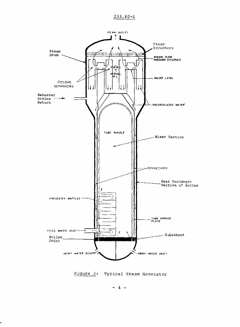
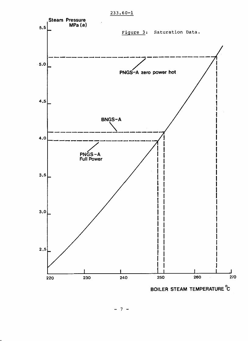
The HT system cools down when the safeties openbecause the boiler pressure falls and hence theaverage boiler water temperature falls too, accordingto the saturation line shown in Figure 3. This inturn will reduce HT average temperature (see III (iii)below) •
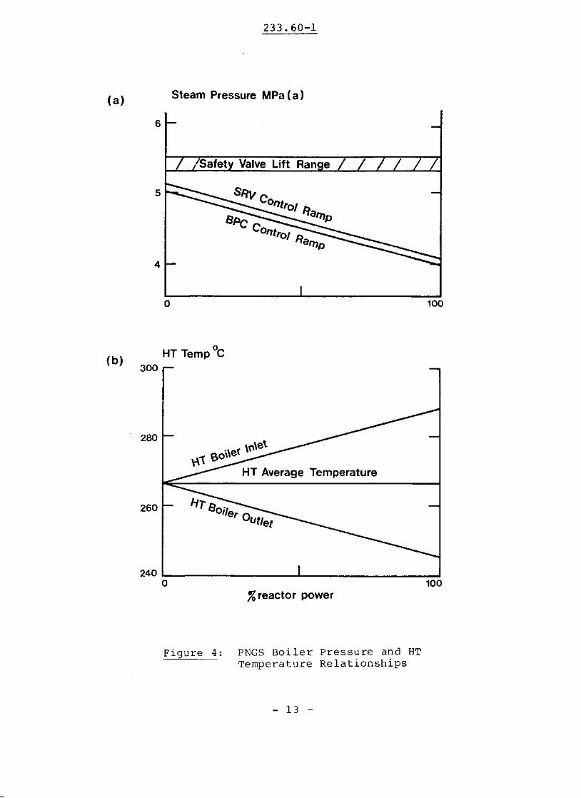
The number of safety valves protecting theboilers is generally between 10 and 20. Liftpressures for these valves are usually staggered sothat all valves do not lift at the same time. Thepurpose of staggered lifts is to ensure that too manysafeties are not used to handle the overpressure,"This then keeps the mechanical and thermal shock tothe steam system to acceptable limits. For a boilersteam system with a maximum operating pressure of S.U3MPa(a) (eg, Pickering in Figure 4) the lifting rangewould be typically from 5.38 MPa(a) to 5.54 MPa(aJ.This range is illustrated in Figure 4 and Figure 5respectively.
(i) This may be waived at the discretion of the inspector.
- 6 -
5.5
5.0
4.5
4.0
3.5
3.0
2.5
233.60-1
Steam PressureMPa (a)
Figure 3: Saturation Data.
----------------------------/
PNGS-A zero power hot
BNGS-A
---------_\_------------~---------
PNGS-AFull Power I
220 230 240 250
BOILER STEAM TEMPERATURE °c
- 7 -
233.60-1
TABLE 1
STEAM SUPPLY SYSTEM VALVE TERMINOLOGY
OPERATING FUNCTIONVALVE NAME
-~--~-~~----~---,,---_._---,--------
TOTAL STEAMFLOW (%F.P.)
-----+------~ic.kering NGS-A
small steamreject valves(SRV's)*
reject steam fromstearn lines to CCWwater intake
5%
large steamreject valves(SRV's)+
reject steam fromsteam lines toatmosphere
100%
-- --t----------
Bruce NGS-A
atmospheric steamdischarge valves(ASDV's)*
discharge steamfrom steam drumto atmosphere
10%
condenser steamdischarge valves(CSDV's)+
discharge steamfrom steam linesto LP condensers
100%li)
-~~--------------------------"--_.
* +, The function of these valves is essentially the same.
Ii) Note the capacity actually used is only 75%, as thecondenser cannot accept full power steam flow.
- 8 -
233.60-1
(d) Stearn Reject Valves
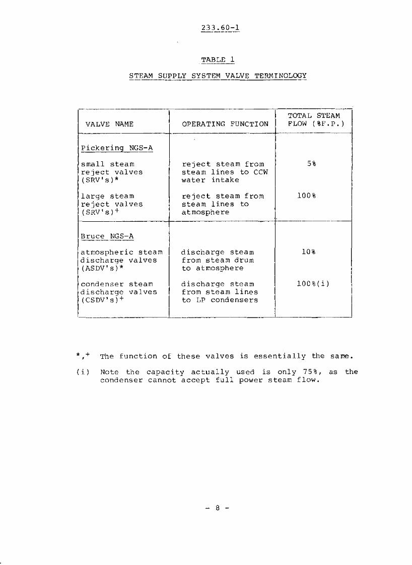
The steam safety valves are required only forboiler overpressure protection and possibly for crash-cool down. These functions do not provide steampressure control, however, which is necessary asdescribed in section IV below. It would be too complex and less reliable for safeties to provide pressure control in addition to pressure relief. Separatevalves are therefore used for pressure control purposes.
The steam pressure control valves are not calledby that name and in fact go under different names indifferent stations. To avoid confusion, Table 1 summarizes the names for pickering NGS and Bruce NGS andalso gives typical percent full power steam reliefcapacity of the valves. The figures for steam reliefcapacity help to illustrate their pressure controlfunctions discussed in section IV (i) and (iil below.
(e) Steam Balance Header
The steam balance header, see Figure I, or mainsteam header as it is also called is a large cylindrical steel vessel. It receives the steam from all theboilers and equalizes the steam pressure before thesteam goes to the turbine. The balance header alsoabsorbs the expansion forces set up by the thermalexpansion of the steam piping as it heats up.
The steam balance header and the steam pipingadjacent to it supply steam to the various locationsin Table 2. The % of total steam flow of each ofthese is quoted to illustrate its importance as far asthe total steam supply is concerned. The steam supplies of importance as far as a reduction in heat sinkcapacity is concerned are then in order of importance:
- turbine- steam plant- reheaters- deaerator supply
- 9 -

233.60-1
TABLE 2
STEAM SUPPLY SYSTEM DESTINATIONS
DESTINATION % OF FULL POWER STEAM
Turbine ",92%
Reheaters ",8%
Turbine Shaft and Turbine "'0.1%Valve Gland Seal
'-hogg iog "-'0.5%Steam Air Ejectors holding "'-'0.05%
Deaerator Supply duringPoison Prevent and Startup "'7%
up to 111 MW(e) equivalentSteam Plant (for BHWP) (Bruce NGS)
Construction Steam up to "'1%
Upgrading Plant Steam up to ",1%.
- 10 -
233.60-1
III. BOILER STEAM PARAMETERS
A general discussion of boiler steam parameters isgiven in this section. Of these parameters the ones whichare controlled, namely boiler pressure and steam flow arediscussed from their control aspects in sections IV and Vbelow.
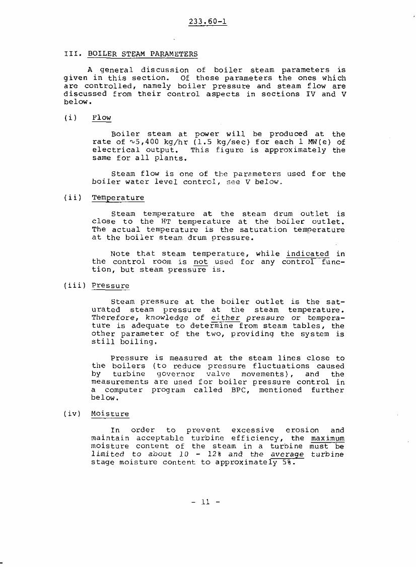
(i) Flow
Boiler steam at power will be produced at therate of "'5,400 kg/hr (1.5 kg/sec) for each 1 MW(e) ofelectrical output. This figure is approximately thesame for all plants.
Steam flow is one of the parameters used for theboiler water level control, see V below.
(ii) Temperature
Steam temperature at the steam drum outlet isclose to the HT temperature at the boiler outlet.The actual temperature is the saturation temperatureat the boiler steam drum pressure.
Note that steam temperature, while indicated inthe control room is not used for any control function, but stearn pressure is.
(iii) Pressure
Steam pressure at the boiler outlet is the saturated steam pressure at the steam temperature.Therefore, knowledge of either pressure or temperature is adequate to determine from steam tables, theother parameter of the two, providing the system isstill boiling.
Pressurethe boilersby turbinemeasurementsa computerbelow.
(iv) Moisture
is measured at the steam lines close to(to reduce pressure fluctuations causedgovernor valve movements), and the
are used for boiler pressure control inprogram called BPC, mentioned further
In order to prevent excessive erosion andmaintain acceptable turbine efficiency, the maximummoisture content of the stearn in a turbine must belimited to about 10 - 12% and the average turbinestage moisture cOntent to approximately 5%.
- 11 -

233.60-1
IV. BOILER PRESSURE CONTROL
Boiler steam pressure cOntrol performs the followingfunctions:
Ii) Matching reactor and turbine power.
Iii) Rapidevent
transfer ofof a turbine
heat sink from the turbinetrip or a .load rejection.
in the
In order to unders tand why s team pressure is used asthe control parameter, one must first understand howthermal power 15 transferred across the tubes of theboiler. This power may be expressed by the relation •
.Q = U.A.T I 1 )
.where Q = the thermal power conducted frolll the heat
transport system to the water in the steamgenerator. IkJ!sec = kW I th) )
U = the overall heat transfer coefficient oftubes. IkJ!m 2/"C!sec)
A = the total tube area. 1m 2 )
T = the difference between the averageheat transport system temperature inthe tubes and the temperature of thewater in the steam generator riser. (OC)
Since A and U are virtuallyis directly proportional to
.independent of reactor power, QT.
The temperature difference T can be wri tten as:
T = TaverageHTS
- 12 -
T S teamgenerator
233.60-1
(a) Steam Pressure MPa(a)
6
5
4
I- -
/ /Safetv Valve Lift Rance / / / / / /
81'1" C -antral 1'1
SPe ampCant, --01 l'1amp
- -I
o 100
(b)o
HT Temp C300
"\e' \,,\et
\\1 eo'HT Average Temperature
firs"Oller 0
"/let
280
260
240 ~ ...L -=.!o 100
%reactor power
Figure 4: PNGS Boiler Pressure and HTTemperature Relationships
- 13 -
233.60-1
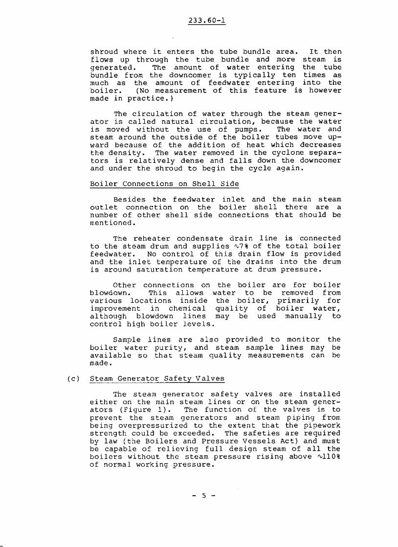
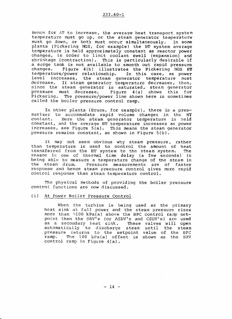
Hence for 6T to increase, the average heat transport systemtemperature must go up, or the steam generator temperaturemust go down, or both must occur simultaneously. In someplants (Pickering NGS, for example) the HT system averagetemperature is held approximately constant as reactor powerchanges, in order to limit coolant swell (expansion) andshrinkage (contraction). This is particularly desirable ifa surge tank is not available to smooth out rapid pressurechanges. Figure 4(b) illustrates the Pickering NGS HTtemperature/power relationship. In this case, as powerlevel increases, the steam generator temperature mustdecrease. If stearn generator temperature decreases, then,since the steam generator is saturated, steam generatorpressure must decrease. Figure 4(a) shows this forPickering. The pressure/power line shown here is sometimescalled the boiler pressure control ramp.
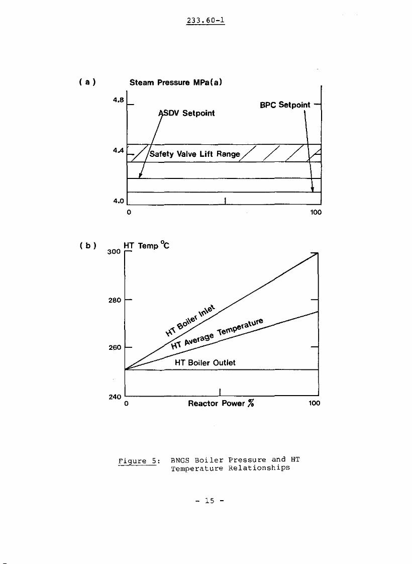
In other plants (Bruce, for example), there is a pressurizer to accommodate rapid volume changes in the HTcoolant. Here the steam generator temperature is heldconstant, and the average HT temperature increases as powerincreases, see Figure 5(a). This means the steam generatorpressure remains constant, as shown in Figure 5(b).
It may not seem obvious why steam pressure, ratherthan temperature is used to control the amount of heattransferred from the HT system to the steam system. Thereason is one of thermal time delay (a few seconds) inbeing able to measure a temperature change of the steam inthe steam drum. Pressure measurements are of fasterresponse and hence steam pressure control gives more rapidcontrol response than steam temperature control.
The physical methods of providing the boiler pressurecontrol functions are now discussed.
(i) At Power Boiler Pressure Control
When the turbine is being used as the primaryheat sink at full power and the steam pressure risesmore than "'100 kPa(a) above the BPC control ramp setpoint then the SRV's (or ASDV's and CSDV's) are usedas a secondary heat sink. These valves will openautomatically to discharge stearn until the steampressure t-eturns to the setpoint value of the BPCramp. The 100 kPa(a) offset is shown as the SRVcontrol ramp in Figure 4(a).
- 14 -
233.60-1
( a ) Steam Pressure MPa(a)
4.8
4A
4.0
!-rOV Setpoint
BPC Setpoint -
'-//Satety Valve Lift Range/ // ~
/I
( b )
o
HT Temp °c300
280
100
260
HT Boiler Outlet
100
240 L- .l-_---:::- ---.J
o Reactor Power %
Figure 5: BNGS Boiler Pressure and HTTemperature Relationships
- 15 -
233.60-1
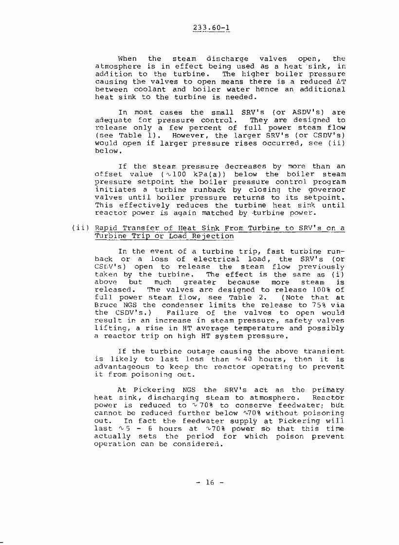
When the stearn discharge valves open, theatmosphere is in effect being used as a heat sink, inado i tion to the turbine. The higher boiler pressu recausing the valves to open means there is a reduced ~T
between coolant and boiler water hence an additionalheat sink to the turbine is needed.
In most cases the small SRV's (or ASDV1s) areadequate for pressure control. They are designed torelease only a few percent of full power steam floW'(see Table 1). However, the larger SRV·s (or CSDV's)would open if larger pressure rises occurred, see (ii)below.
If the steam pressure decreases by more than anoffset value ('VIDa kPa(a)) below the boiler steampressure setpoint the boiler pressure control programinitiates a turbine runback by closing the governorvalves until boiler pressure returns to its se'tpoint.This effectively reduces the turbine heat sink untilreactor power is again matched by -turbine power.
(ii) Rapid Transfer of Heat Sink From Turbine to SRV's on aTurb~~~rip or Load Rejection
In the event of a turbine trip, fast turbine runback or a loss of electrical I-oad, the SRV' s (orCS[;v· s) open to release the steam flow previollslytaken by the turbine. The effect is the same as (i')above but much greater because more stearn isreleased. The valves are designed to release 100% offull power steam flow, see Table 2. (Note that atBruce NGS the condenser limits the release to 75% viathe CSDV's.) Failure of the valves to open wouldresult ip. an increase in stearn pressure, safety valveslifting, a rise in HT average temperature and possiblya reactor trip on high HT system pressure.
If the turbine outage causing the above transientis likely to last less than'" 40 hours, then it isadvantageous to keep the reactor operating to preven-tit from poisoning out.
At Pickering NGS the SRV's act as the primaryheat sink, discharging steam to atmosphere. Reactorpower is reduced to '" 70% to conserve feedwater; bU-tcannot be reduced further below "'70% without poisoningout. In fact the feedwater supply at Pickering willlast'" 5 - 6 hours at "'70% power so that this timeactually sets the period for which poison preventoperation can be consideren.
- 16 -
233.60-1
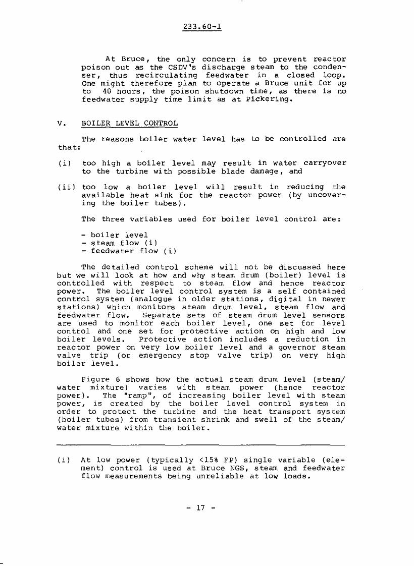
At Bruce, the only concern is to prevent reactorpoison out as the CSDV's discharge s team to the condenser, thus recirculating feedwater in a closed loop.One might therefore plan to operate a Bruce unit for upto 40 hours, the poison shutdown time, as there is nofeedwater supply time limit as at pickering.
v. BOILER LEVEL CONTROL
The reasons boiler water level has to be controlled arethat:
(i) too high a boiler level may result in wa ter carryoverto the turbine wi th possible blade damage, and
( i i ) too low a boiler level will resul t inavailable heat sink for the reactor powering the boiler tubes).
reducing the(by uncover-
The three variables used for boiler level control are:
- boiler level- stearn flow (i)- feedwater flow (i)
The detailed control scheme will not be discussed herebut we will look at how and why steam drum (boiler) level iscontrolled with respect to steam flow and hence reactorpower. The boiler level control system is a self containedcontrol system (analogue in older stations, digital in newers ta tions) Which moni tors s team drum level, steam f low andfeedwater flow. Separate sets of steam drum level sensorsare used to monitor each boiler level, one set for levelcontrol and one set for protective action on high and lowboi ler levels. Protec ti ve ac tion includes a reduc tion inreactor power on very low boiler level and a governor steamvalve trip (or emergency stop valve trip) on very highboiler level.
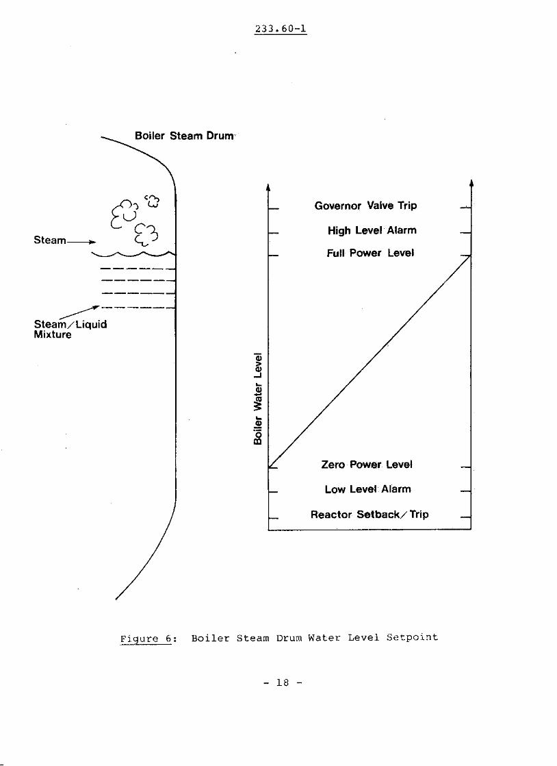
Figure 6 shows how the actual steam drum level (steam/water mixture) varies with steam power (hence reactorpower). 'l'he "ramp", of increasing boiler level with steampower, is crea ted by the boi ler level can trol sys tern inorder to protect the turbine and the heat transport system(boiler tubes) from transient shrink and swell of the steam/water mixture wi thin the boiler ~
(i) At low power (typically <15% FF) single variable (element) control is used at Bruce NGS, steam and feedwaterflow measurements being unreliable at low loads.
- 17 -
233.60-1
Boiler Steam Drum<
Sleam---..
Governor Valve Trip
High Level Alarm
Full Power Level
~-----
Steam/LiquidMixture
Zero power Level
Low Level Alarm
Reactor Setback/ Trip
Figure 6: Boiler Steam Drum Water Level Setpoint
- 18 -
233.60-1
Increase Will IncreaseLevel
Increase Will DecreaseLevel
Main Steam>-BOILER
er >- LEVEL
r
'"ReheateDrains Blowdown
FeedwatFlow
ReactorPower
Figure 7: Factors Which Influence Boiler Level
- 19 -

233.60-1
Swell in the boiler occurs during an increase insteaming rate, due to an increased volume of entrainedsteam. If there is an increase in steam flow from theboiler the boiler pre'ssure will drop causing a rapidincrease in the steaming rate. This sudden increase inentrained steam will cause a rise in the steam/water levelwithin the steam drum. 'l'his swell is a transient effectlasting a matter of seconds.
Shrink in the boiler OCcurs during a decrease insteaming rate, due to the decreased volume of entrainedsteam. If there is a decrease in steam flow from theboiler the pressure will increase causing a rapid decreasein the steaming rate. This sudden decrease will cause adrop in the steam/water level wi thin the steam drum. 'l'heshrink is also a transient effect lasting a matter ofseconds.
Notice that while the terms "swell" and 11 s hrink" arethe same as those used in reference to the primary heattransport system, the effect here is entirely different.(Remember swell and shrink in the PHT system refer toexpansion and contraction of liquid D20 dUE! to temperaturechanges. )
To provide maximum protection of the system againstswell and shrink in the boiler, a programmeCl boiler level(determiiled by steam power) is used. This programmed levelinsures that the level is highest when the risk of shrinkis the greatest (at maximum steam power) and also insuresthat the level is lowest when the risk of swell is greatest(at minimum steam power).
The high and low boiler level alarms have setpointsslightly above and below the programmed boiler level ramp,respectively.
All plants provide for manual adjustment of boilerlevel in case of a feedwater control valve failure. Boilerblowdown lines may be used for this purpose once the defective feedwater valve has been isolated using other valveson the defective line. Opening a blowdown line tends todecrease boiler level. (The capacity of the blowdownlines, however, is much less than the normal feedwater orsteam flow.)
Boiler isolating valves, in each boiler feed waterinlet line may also be adjustable (remote manual)throttling open tends to raise boiler level, throttlingclosed tends to lower boiler level. This trimming ofboilee water level is done, especially at pickering NGS-A,during fuelling operations and during adjuster rod movementto adjust individual boiler steaming rates and hence boilerlevels to the same values. Inefficient mi<xing of liT D20 in
- 20 -
233.60-1
the reactor outlet header(s) can result in different steaming rates between boilers served by the same HT header.The boiler feedwater valve serving these boilers will thennot be able to rna tch feedwa ter flow to s team flow for eachboiler in the group when channel powers change in core.Use of the individual boiler isolating valves for trimmingof boiler levels is then done despite the fact the isolating valves are not designed for control.
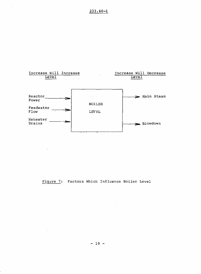
Summarizing all the factors which can influence boilerlevel, Figure 7 illustrates those which tend to increase ordecrease boiler level.
ASSIGNMENT
1. If your plant is not Pickering NGS nor Bruceis your stations equivalent of the valvesTable 1.
NGS, whatgiven in
2. On Figures 4 and 5 plot the average boiler steam temperature between 0% and 100% power using data fromFigure 3. Indicate how T from equation (i) can becalculated from the graphs.
D.J. WinfieldV. DIAngelo
- 21 -