read and save these instructions dri-steem gts and gts …m)-1199.pdf · read and save these...
TRANSCRIPT

READ AND SAVE THESE INSTRUCTIONS
DRI-STEEMDRI-STEEMDRI-STEEMDRI-STEEMDRI-STEEMGTSGTSGTSGTSGTS®®®®® and GTS and GTS and GTS and GTS and GTS®®®®®-DI-DI-DI-DI-DI
EUREUREUREUREUROPEAN MODELOPEAN MODELOPEAN MODELOPEAN MODELOPEAN MODELGAS-TGAS-TGAS-TGAS-TGAS-TO-STEAM HUMIDIFIERSO-STEAM HUMIDIFIERSO-STEAM HUMIDIFIERSO-STEAM HUMIDIFIERSO-STEAM HUMIDIFIERS
Installation, OperationInstallation, OperationInstallation, OperationInstallation, OperationInstallation, Operationandandandandand
Maintenance ManualMaintenance ManualMaintenance ManualMaintenance ManualMaintenance Manual
This manual must be left with the owner and should be accessible for reference.
WARNING: If the information in this manualis not followed exactly, a fire or explosionmay result causing property damage,personal injury, or loss of life.
• Do not store or use gasoline or other flammable vapors andliquids in the vicinity of this or any other appliance.
WHAT TO DO IF YOU SMELL GAS• Do not try to light any appliance.
• Do not touch any electrical switch; do not use anyphone in your building.
• Immediately call your gas supplier from an off-sitephone. Follow the gas supplier's instructions.
• If you cannot reach your gas supplier, call the firedepartment.
• Installation and service must be performed by a qualifiedinstaller, service agency, or the gas supplier.
GTSOM(m)-1199.pdf 1 11/17/2009 4:09:59 PM

2
TO THE PURCHASER AND THE INSTALLERTO THE PURCHASER AND THE INSTALLERTO THE PURCHASER AND THE INSTALLERTO THE PURCHASER AND THE INSTALLERTO THE PURCHASER AND THE INSTALLERThank you for purchasing DRI-STEEM Model GTS® equipment. Wehave designed and built this equipment to give you total satisfactionand many years of trouble-free service. Proper installation andoperating practices will assure you of achieving that objective. Wetherefore urge you to become familiar with the contents of thismanual.
This equipment has been tested by Canadian Standards AssociationInternational to the low voltage, gas appliance, and EMC directivesand has been approved by AFNOR for use in all EU countries.
DRI-STEEM Humidifier CompanyDRI-STEEM Humidifier CompanyDRI-STEEM Humidifier CompanyDRI-STEEM Humidifier CompanyDRI-STEEM Humidifier Company
AUTHORIZED COUNTRIES OF DESTINATIONAUTHORIZED COUNTRIES OF DESTINATIONAUTHORIZED COUNTRIES OF DESTINATIONAUTHORIZED COUNTRIES OF DESTINATIONAUTHORIZED COUNTRIES OF DESTINATIONThe GTS and GTS-DI humidifiers bearing the CE mark areauthorized for use in the European countries listed below.
Austria AT Greece GRBelgium BE Ireland IESwitzerland CH Iceland ISGermany DE Italy ITDenmark DK Luxembourg LUSpain ES Netherlands NLFinland FI Norway NOFrance FR Portugal PTUnited Kingdom GB Sweden SE
APPLIANCE CATEGORYAPPLIANCE CATEGORYAPPLIANCE CATEGORYAPPLIANCE CATEGORYAPPLIANCE CATEGORYIn relation to the country of destination, this humidifier is classifiedunder one of the following boiler categories: category I
2H, I
2L, I
2E, I
2E+,
I2LL
, I2ES
, I2Fi
, or I2ER
.
See the unit data plate for the specific category of your appliance.
FOREWORDFOREWORDFOREWORDFOREWORDFOREWORD
GTSOM(m)-1199.pdf 2 11/17/2009 4:10:02 PM

3
GTS Program Code NomenclatureGTS Program Code NomenclatureGTS Program Code NomenclatureGTS Program Code NomenclatureGTS Program Code Nomenclature ...................................... 4
Models GTS and GTS-DIModels GTS and GTS-DIModels GTS and GTS-DIModels GTS and GTS-DIModels GTS and GTS-DI ...................................................... 5
Safety PrecautionsSafety PrecautionsSafety PrecautionsSafety PrecautionsSafety Precautions ................................................................ 6
Specifications and CapacitiesSpecifications and CapacitiesSpecifications and CapacitiesSpecifications and CapacitiesSpecifications and Capacities .............................................. 7
DimensionsDimensionsDimensionsDimensionsDimensions ........................................................................... 8
InstallationInstallationInstallationInstallationInstallationPrecautions ................................................................ 9Required Clearance ..................................................... 9Locating the Humidifier ............................................... 10Supply Water and Drain Overflow Connections ........... 10Makeup Water Piping and Material .............................. 11Drain Piping and Material ............................................ 11Gas Piping .................................................................. 12Gas Leak Testing ....................................................... 13Electrical .................................................................... 13Combustion and Ventilation Air ................................... 14Flue Venting Guidelines (Stack Connection) ............... 15
Mounting the HumidifierMounting the HumidifierMounting the HumidifierMounting the HumidifierMounting the HumidifierFloor Stand ................................................................. 16Indoor Cover ............................................................... 16Outdoor Enclosure ...................................................... 17
Steam Supply Connection MethodsSteam Supply Connection MethodsSteam Supply Connection MethodsSteam Supply Connection MethodsSteam Supply Connection Methods .................................... 21
Condensate Return PipingCondensate Return PipingCondensate Return PipingCondensate Return PipingCondensate Return Piping ................................................... 22
RAPID-SORBRAPID-SORBRAPID-SORBRAPID-SORBRAPID-SORB®®®®® Assembly and Installation Assembly and Installation Assembly and Installation Assembly and Installation Assembly and InstallationHorizontal Duct Installation .................................... 23Vertical Duct Installation ......................................... 24
ULTRA-SORBULTRA-SORBULTRA-SORBULTRA-SORBULTRA-SORB®®®®® Installation Installation Installation Installation Installation ................................................... 24
AREA-TYPE ApplicationAREA-TYPE ApplicationAREA-TYPE ApplicationAREA-TYPE ApplicationAREA-TYPE Application ....................................................... 25
Start-up and OperationStart-up and OperationStart-up and OperationStart-up and OperationStart-up and Operation ......................................................... 26
MaintenanceMaintenanceMaintenanceMaintenanceMaintenanceGTS (Standard Model Only) ........................................ 27GTS-DI Model Only .................................................... 27Both GTS and GTS-DI ................................................ 28
Replacement PartsReplacement PartsReplacement PartsReplacement PartsReplacement Parts ................................................................ 28
Wiring DiagramsWiring DiagramsWiring DiagramsWiring DiagramsWiring Diagrams ................................................................... 33
Caution LabelsCaution LabelsCaution LabelsCaution LabelsCaution Labels ...................................................................... 37
Maintenance Service RecordMaintenance Service RecordMaintenance Service RecordMaintenance Service RecordMaintenance Service Record ................................................ 38
Two-Year Limited WarrantyTwo-Year Limited WarrantyTwo-Year Limited WarrantyTwo-Year Limited WarrantyTwo-Year Limited Warranty .................................................. 40
TTTTTABLE OF CONTENTSABLE OF CONTENTSABLE OF CONTENTSABLE OF CONTENTSABLE OF CONTENTS
GTSOM(m)-1199.pdf 3 11/17/2009 4:10:02 PM

4
GTS PRGTS PRGTS PRGTS PRGTS PROGRAM CODE NOMENCLAOGRAM CODE NOMENCLAOGRAM CODE NOMENCLAOGRAM CODE NOMENCLAOGRAM CODE NOMENCLATURETURETURETURETURE
A 14-digit VAPOR-LOGIC®3 program code appears
on the front of the control cabinet and on thewiring diagram inside the control cabinet. Theprogram code specifies the parameters of theVAPOR-LOGIC3 microprocessor, which controlsyour humidification system. An explanation of theprogram code is detailed below.
VAPOR-LOGIC3 program code
A. VAPOR-LOGIC3 system type:G = GTS®
S = STS®
L = LTS®
V = VAPORSTREAM®
M = VAPORMIST®
C = CRUV®
U = ULTRA-FOG®
N = Steam Injection
B. VAPOR-LOGIC3 board classification:1 = One-tank system2 = Two-tank system3 = Three-tank system4 = Four-tank system5 = Five-tank system6 = Six-tank system
C. Digital display/keypad features:1 = Single keypad
D. Type of outputs:0 = Steam valve/100% SSR1 = One heat stage2 = Two heat stages3 = Three heat stages4 = Four heat stages
E. System pounds output:##### = Output capacity(e.g., 00285 = output capacity in lbs/hr)
F. Type of water level control:D = DI w/ manual drainE = DI w/ end of season drainM = Standard w/ manual drainA = Standard w/ autodrain
G. Operating mode:1 = Single staged2 = Externally staged3 = not used4 = not used5 = not used6 = GTS7 = TP8 = SSR9 = Steam valve
H. VAV options:V = Option presentO = Option not selectedS = SDU option
I. Temperature compensation options:T = Option presentO = Option not selected
J. Type of humidity sensing device:N = None, for on/offC = 0-135 ohm humidistatD = 6-9 VDC humidistatH = 0-10 VDC humidistatE = 4-20 mA humidistatX = 4-20 mA transmitterQ = Dew point transmitterS = Special
GTSOM(m)-1199.pdf 4 11/17/2009 4:10:02 PM

5
GTSGTSGTSGTSGTS®®®®® AND GTS-DI HUMIDIFIERS AND GTS-DI HUMIDIFIERS AND GTS-DI HUMIDIFIERS AND GTS-DI HUMIDIFIERS AND GTS-DI HUMIDIFIERS
GTS Gas-to-SteamHumidifierThe GTS is a gas-fired humidifier thatburns natural gas to generate steamfor humidification. The unit consistsof one or two burners, which are firedinto a heat exchanger. This heatexchanger is, in turn, submerged in atank of water. When there is a call forhumidity, the burners fire and gener-ate steam until the call for humidityends. The GTS is compatible with alltypes of DRI-STEEM dispersiondevices, including RAPID-SORB®
and ULTRA-SORB®.
The GTS humidifier is designed to beused with all water types. Thestandard GTS model supportssoftened or unsoftened water anduses a probe-type level controlsystem to sense water level. Thisprobe requires water conductivity of100 μm/cm (about 2 gr/gal minimum)to function. Therefore, it will notoperate on water treated by reverseosmosis or deionization.
The GTS-DI model is available foruse with deionized or reverse osmo-sis water. This unit produces chemi-cal-free steam and reliable, accuratehumidification control. It is virtuallymaintenance-free, with no wastedwater, heat, or downtime. The DI unituses a float valve to control waterlevels. The standard GTS model canbe converted to a GTS-DI model inthe field.
OM-1084
Drain Valve
GasValve
Probes or Float
Fill Valve
Heat Exchanger
Evaporating ChamberCover
Blower
ULTRA-SORB®
Cover Knob
Control Panel
Shroud
Flue Box
GTSOM(m)-1199.pdf 5 11/17/2009 4:10:03 PM

6
SAFETY PRECASAFETY PRECASAFETY PRECASAFETY PRECASAFETY PRECAUTIONSUTIONSUTIONSUTIONSUTIONS
WARNING:Improper installation, adjustment, alteration, service,maintenance, or use can cause carbon monoxidepoisoning, an explosion, fire, electrical shock, or otherconditions which may cause personal injury or propertydamage. Consult a qualified installer, service agency,local gas supplier, or your distributor or branch forinformation or assistance. The qualified installer oragency must use only factory authorized and listed kitsor accessories when modifying this product. A failureto follow this warning can cause electrical shock, fire,personal injury, or death.
• Inspect humidifier and accessories upon arrival fordamaged, missing, or improper parts. If there is aproblem, call DRI-STEEM.
• Application of this humidifier should have specialattention given to vent sizing and material, gas inputrate, and unit sizing. Improper installation or misappli-cation of the humidifier can cause excessive servicingor permanent component failure.
• When working on equipment, observe precautions inthis literature, tags, and labels attached to or shippedwith the unit and other safety precautions that mayapply. Wear safety glasses and work gloves. Have afire extinguisher available during start-up, adjustmentprocedures, and service calls.
• Do not use this appliance if any part has been underwater. Immediately call a qualified service technician toinspect the appliance and to replace any part of thecontrol system and any gas control which has beenunder water.
• Do not lift humidifier by gas controls, gas manifold,fire box, or control shroud.
• Should overheating occur, or the gas supply fail toshut off, shut off the manual gas valve to the appliancebefore shutting off the electrical supply.
• This equipment is for use with second family (G20,G25) natural gases only.
• Conversion to another group or supply pressureshould be carried out by a competent person.
Conversion Instructions:
• No replacement parts are required for conversion.
* A flat screwdriver will be required to adjust the gasvalve throttle screw. A combustion analyzer and pres-sure gauge will be required to ensure proper adjustment.A gas meter must be installed on the incoming gassupply to ensure proper input. Turning the throttle screwcounter-clockwise will increase the gas input, clockwisedecreases input. Use the gas meter and analyzer todetermine proper combustion at the stated input.
• Throttle screw seal shall be replaced upon completionof adjustment.
• For appliances operating with a pressure couple, anygovernor shall be made inoperative.
• Contact an authorized DRI-STEEM distributor toreceive the proper replacement data plate.
Electrical Warning Label:
Location: Control cover, shroudDefinition: Electrical shock hazard
GTSOM(m)-1199.pdf 6 11/17/2009 4:10:03 PM

7
SPECIFICATIONS AND CAPACITIES
Table 7-1: Specifications
Capacity Notes• Approximately 402 kJ are required to raise the tem-perature of one kg of water from 4°C to 100°C.
• An additional 2257 kJ are required to change one kgof water to water vapor.
• Another factor to consider is condensation steam lossfrom hoses and tubes. Use the following steam lossguidelines:
- vapor hose: 0.22 kg/m/h- insulated pipe: 0.07 kg/m/h- dispersion tubes: 0.7 kg/m/h
• The maximum steam capacities listed may be asmuch as 10% higher than the give values due to localvariations in the Wobbe index of G20 and G25 gases.
ledoMrebmun
maetSyticapacruohrep
gkni
)Wk(=P )Wk(=QmaetSteltuo
dednemmoceRnieziseulfmm/sehcni)BssalC(
gnitarepOthgiew
gkni
gnippihSthgiew
gkni
roodtuOerusolcnegnitarepo
gknithgiew
roodtuOerusolcne
gnippihsnithgiew
gk
lluF*daolspma
001-STG 73 02-0 42-0PSB)"2(05NDesoh05NDro
)"5(521ND 592 591 094 583 9.2
002-STG 37 84-0 95-0PSB)"2(05NDesoh05NDro
)"5(521ND 592 591 094 583 9.2
003-STG 011 27-0 88-0 egnalf)"3(08ND )"7(081ND 014 522 006 024 5.3
004-STG 021 08-0 79-0 egnalf)"3(08ND )"7(081ND 014 522 006 024 5.3
Operating Characteristics:Operating Characteristics:Operating Characteristics:Operating Characteristics:Operating Characteristics:• Unit is capable of operating in ambient conditions of5°C - 40°C.
• Unit is capable of operating in ambient conditionsbetween 30% RH and 95% RH (non-condensing).
• NOx class 5
Gas Supply Pressure:Gas Supply Pressure:Gas Supply Pressure:Gas Supply Pressure:Gas Supply Pressure: 20 mbar or 25 mbar, dependingon gas group. See data plate information.
PMS (all units):PMS (all units):PMS (all units):PMS (all units):PMS (all units): 7.0 bar
Electric Supply: Electric Supply: Electric Supply: Electric Supply: Electric Supply: 230V, 667W-2415W (see data plate)
Max Inlet Water Temperature:Max Inlet Water Temperature:Max Inlet Water Temperature:Max Inlet Water Temperature:Max Inlet Water Temperature: 90°C
* For units with outdoor enclosure, add 7A for electric heater load.
Table 7-2: Volumetric flow rate by gas category and other characteristics
Humidifiermodel
Volumetric flow rate by gas category
Average fluetemperature
Minimumdraught
requirement
Mass flowrate of
combustionproducts
2H-G20-20 mbar2E-G20-20 mbar2Es-G20-20 mbar
2L-G25-25 mbar2LL-G25-20 mbar2Ei-G25-25 mbar
2E+G20/G25-20/25 mbar2ER-G20/G25-20/25 mbar
GTS 100 2.31 m3/h 2.82 m3/h 2.31-2.82 m3/h 121 C -0.025 mbar 6.9 g/s
GTS 200 4.62 m3/h 5.64 m3/h 4.62-5.64 m3/h 163 C -0.025 mbar 13.8 g/s
GTS 300 6.92 m3/h 8.46 m3/h 6.92-8.46 m3/h 191 C -0.025 mbar 20.7 g/s
GTS 330 7.62 m3/h 9.31 m3/h 7.62-9.31 m3/h 218 C -0.025 mbar 22.8 g/s
GTSOM(m)-1199.pdf 7 11/17/2009 4:10:03 PM

8
DIMENSIONSDIMENSIONSDIMENSIONSDIMENSIONSDIMENSIONS
Figure 8-1: DimensionsFigure 8-1: DimensionsFigure 8-1: DimensionsFigure 8-1: DimensionsFigure 8-1: Dimensions
Side Side Side Side Side VieVieVieVieViewwwww
A
K
H
R
S
B
TTTTTop op op op op VieVieVieVieViewwwww
LJ
Q
P
E
FrFrFrFrFront ont ont ont ont VieVieVieVieViewwwwwN
F
D
GC
M
GTSOM(m)-1199.pdf 8 11/17/2009 4:10:03 PM

9
INSTINSTINSTINSTINSTALLAALLAALLAALLAALLATIONTIONTIONTIONTION
Precautions• Installation must conform to the requirements of theauthority having jurisdiction.
• Do not install in potentially explosive or flammableatmospheres laden with grain dust, sawdust, or similarairborne materials.
• Installation of humidifier in high humidity or salt wateratmospheres will cause accelerated corrosion, resultingin a reduction of the normal life-span of the unit.
• To prevent premature heat exchanger failure, do notlocate ANY gas-fired unit in areas where chlorinated,halogenated or acid vapors are present in theatmosphere.
• Locate the humidifier in an area clear of combustiblematerials, gasoline, and other flammable vapors andliquids.
• With the exception of sealed combustion units, donot locate units in tightly sealed rooms or smallcompartments without provision for adequatecombustion air and venting. Room air combustion mustbe supplied through a minimum of two permanentopenings in the wall, at least one near the bottom. Theopenings should provide 22 cm2 per kW free area per300W input rating of the unit, with a minimum of 650cm2 for each opening. See table 14-1 and information onpages 14 and 15 for additional information.
• Remove all shipping brackets and materials beforeoperating the humidifier.
• Humidifier flue gases must be vented to the outsideatmosphere.
• Power supply disconnect switch must be in the offposition while making wiring connections to preventelectrical shock and equipment damage. All units mustbe wired in strict accordance with wiring diagramfurnished with this unit.
• Turn off all gas while installing the gas piping andmanual shut-off valve for the humidifier.
GTS clearance recommendationsGTS clearance recommendationsGTS clearance recommendationsGTS clearance recommendationsGTS clearance recommendations
Handling instructions:
• Keep unit upright during handling.• Do not lift unit by control cabinet or shroud.• Do not bend electrical conduit past 90°.
Cover 457 mm
Heatexchanger
762 mm
Controlcabinet914 mm
Burnershroud
762 mm
OM-1081
Required Clearance:For recommended service and maintenance purposesthe following clearances should be maintained:
• Heat exchanger removal - front, 750 mm• Burner shroud removal - front, 750 mm• Control cabinet - right side, 915 mm• Cover removal - top, 450 mm• Distance from vent box to combustible floor - 750 mm• A minimum of 25 mm clearance is recommended between hot surfaces and combustible walls.
GTSOM(m)-1199.pdf 9 11/17/2009 4:10:03 PM

10
INSTINSTINSTINSTINSTALLAALLAALLAALLAALLATIONTIONTIONTIONTION
Locating the Humidifier• Provide a level, solid foundation for the humidifier.Locate the humidifier as near as possible to chimney oroutside wall so that the flue pipe from the humidifier isshort and direct. The location should also be such thatthe gas ignition system components are protected fromwater during humidifier operation and service.
• The humidifier should be installed in a location awayfrom drafts and properly protected. If installed in aseparate room, follow the instructions concerningcombustion and ventilation air.
• The humidifier should be located in an area whereleakage from the tank or its connections will not resultin damage to the adjacent structure or to lower floors ofthe structure. When such locations cannot be avoided,it is recommended that a suitable drain pan, adequatelydrained, be installed under the humidifier. The pan mustnot restrict combustion air flow.
• The humidifier must not be installed on carpeting,tile, or other combustible material other than woodflooring (indoor application only).
• Install humidifier so electrical components areprotected from water.
• The appliance must be kept free and clear of insulat-ing materials when located in an insulated space.Insulating material may be combustible. Inspection ofthe appliance area must be performed when the appli-ance is installed, or when insulation is added.
• Locate the humidifier in an area where operatingnoise will not be objectionable.
• The VAPOR-LOGIC®3 keypad should be mounted in
an easily accessible location for the operator between0.4 m and 2.0 m above the floor.
Important:• Remove all shipping brackets and materials beforeoperating the humidifier.
• Humidifier flue gases must be vented to the outsideatmosphere.
• Power supply disconnect switch must be in the offposition while making connections to prevent electricalshock and equipment damage. All units must be wiredin strict accordance with wiring diagram furnished withthis unit.
• Turn off all gas while installing the run-out andmanual shut-off valve for the humidifier.
Supply Water and Drain OverflowConnectionsIMPORTANT: The humidifier is shipped with theautomatic drain valve locked in the manual openposition. This position reduces the possibility ofdamaging the valve seat from the heat of sweating thedrain connection during installation. After the drainconnection has been completed, the “manual open”lever position must be reset to the auto position. Failureto close the drain valve will not allow the tank to fill.
Regardless of the type of water used, the followinggeneral instructions must be followed:
• Union connections must be made at the humidifier onthe cold water supply and drain/overflow lines.
• A shut-off valve should be provided in the supplywater line to isolate the humidifier from the watersystem while servicing.
• If the water pressure is above 420 kPa (60 psig) and/or water hammer would be objectionable, a pressurereducing valve or shock arrester should be installed.
• A 25 mm opening is provided in the humidifier tank toaccommodate skim and/or overflow protection. (Note:Follow local code requirements regarding size of drainpipe.)
• Insulating unions or bushings must be used to makeconnections between copper and other dissimilar metalfittings, such as galvanized steel. These insulatingfittings are required to minimize electrolytic corrosion,which results from the direct connection of dissimilarmetals in a water system.
• Before beginning ignition sequence of the humidifierat a new installation, be sure the humidifier tank is fullof water and the water is free to flow into the tank.
GTSOM(m)-1199.pdf 10 11/17/2009 4:10:03 PM

11
INSTINSTINSTINSTINSTALLAALLAALLAALLAALLATIONTIONTIONTIONTION
Makeup Water Piping and MaterialMakeup Water Piping and MaterialMakeup Water Piping and MaterialMakeup Water Piping and MaterialMakeup Water Piping and MaterialMinimum makeup water pressure must be 175 kPa.When nonmetallic water piping is used, it must be ratedto withstand 100°C or greater temperature. If not, thefinal three feet connected to the humidifier should bemetallic and should not be insulated.
As part of the fill valve assembly, the needle valverestricts the rush of cold water entering the evaporatingchamber during the fill cycle. Adjusting the supplywater flow with the needle valve will reduce fill cycle
OM-737N
* Drain piping material must be suitable for 100°C water.** Refer to local codes for drain pipe sizing and maximum temperature
requirements.
DI WaterDI WaterDI WaterDI WaterDI Water
noise from the collapsing steam head in the humidifier.Adjusting the needle valve will also reduce the drop inoutput during a fill cycle. Care must be taken to notreduce the fill rate below the humidifier's capacity, asthis will cause a low-water shutdown.
Drain Piping and MaterialDrain Piping and MaterialDrain Piping and MaterialDrain Piping and MaterialDrain Piping and MaterialIf nonmetallic pipe or hose is used, it must be capableof withstanding temperatures up to 100°C.
DN6 (¼") water supply line175 kPa minimum
Steam outlet
SST manualdrain valve
Water skim/overflow outlet
Air gap
Open drain**
Shroud
Float-operated lowwater cutoff
Float-operated watermakeup valve
Flue connection
Drain piping*(by installer)
OM-736N
Standard WaterStandard WaterStandard WaterStandard WaterStandard Water
DN6 (¼") water supply line175 kPa minimum
Steam outlet
Manual electric drain valve
Water skim/overflow outlet
Air gap
Open drain**
Shroud
Three-probe level controland low water cutoff
Solenoid watermakeup valve
Flue connection
Drain piping* (by installer)
Redundant low water cutoff sensor
Condensate plug
GTSOM(m)-1199.pdf 11 11/17/2009 4:10:03 PM

12
INSTINSTINSTINSTINSTALLAALLAALLAALLAALLATIONTIONTIONTIONTION
Gas Piping Guidelines
CAUTION:Gas pressure to humidifier controls must neverexceed 5.98 kPa. A DN3 (1/8") plugged tapping,accessible for test gauge connection, must beinstalled immediately upstream of the gas supplyconnection to the appliance.
• After threading and reaming the ends, inspect pipingand remove loose dirt and chips.
• Support piping so that no strains are imposed on unitor controls.
• Use two wrenches when connecting piping to unitcontrols.
• Provide a drip pocket before each unit and in the linewhere low spots cannot be avoided.
• Takeoff to unit should come from top or side of mainto avoid trapping condensate.
• Piping subject to wide temperature variations shouldbe insulated.
• Pitch piping up toward unit at least 7 mm per 5 m ofhorizontal run.
• Compounds used on threaded joints of gas pipingmust be resistant to the harmful action of liquefiedpetroleum gases.
• Purge air before lighting unit by disconnecting pipingat gas control. In no case should line be purged intoheatexchanger.
• After installation, check field piping and humidifier gastrain for gas leaks.
• Do not use soap solution, or open flame on humidifiergas train. A gas leak detector is recommended.
• Install a ground joint union and a manual shut-offvalve immediately upstream of the unit including a DN3(1/8") plugged tapping accessible for test gauge connec-tion. Pressure tappings for test gauges are located onall gas valves.
• Allow at least 1.5 m of piping between any highpressure regulator and unit pipe connection.
• Piping installation must be in accordance with localcodes. Do not use flexible connectors.
• Piping to units should conform with local and nationalrequirements for type and volume and gas handled, andpressure drop allowed in the line. Refer to table 13-1,
and 13-2 to determine the volumetric flow rate for thetype of gas and size of unit to be installed. Using thisvalue and the length of pipe necessary, determine thepipe diameter. Where several units are served by thesame main, the total capacity, gas flow (cfh), and lengthof main must be considered. Avoid pipe sizes smallerthan DN13 (1/2"). Table 13-1 allows for the usualnumber of fittings at the stated pressure drop.
Table 13-2 should be used when the specific gravity ofthe gas is other than .60 for natural gas.
Gas Leak Testing• When leak testing the gas supply piping system, thehumidifier and its gas shut-off valve must be discon-nected during any pressure in excess of 5.98 kPa. Thehumidifier must be isolated from the gas supply pipingsystem by closing its field-installed manual shut-offvalve during any pressure not equal to 5.98 kPa.
• Check gas supply pressure with all burners running atinlet pressure tap of combination gas control. Therecommended supply pressure should be 1750 Pa onnatural gas. The minimum supply pressure is 1495 Pafor natural gas.
Gas PipingGas PipingGas PipingGas PipingGas Piping
OM-1087
Gas supply line
Drip pocket***
7.5 mm min.
Plugged DN6(1/8")test gageconnection***
Humidifiershroud
To gas valve
Gas cock***DN15 (½")tubing
DN25(1")
tubing
To gas valve
DN15(½") xDN 15(½") xDN25 tee (byDRI-STEEM)
OM-1086
Gas supply line
Drip pocket***
75 mm min.
Plugged DN6(1/8")test gageconnection***
Humidifiershroud To gas valve
Gas cock***
DN13 (½") piping
DN13 (½") unionby DRI-STEEM
GTSOM(m)-1199.pdf 12 11/17/2009 4:10:04 PM

13
Electrical Connections
CAUTION:Do not connect aluminum wire between disconnectswitch and humidifier. Use only copper wire.WARNING:The cabinet must have an uninterrupted or unbrokenground to minimize personal injury if an electrical faultshould occur. This may consist of electrical wire orconduit approved for electrical ground when installed inaccordance with existing electrical codes. Do not usegas piping as an electrical ground.
• GTS Humidifiers need to be supplied with 230V/1~/50Hz, separately fused electrical service. The GTShumidifier is equipped with a transformer to step downthe voltage to 24 VAC control voltage.
• When installed, the GTS humidifier must be electri-cally grounded in accordance with local codes. Theelectrical conductors shall be of the appropriate wire sizeand rate for at least 105°C. All electrical componentsand wiring must be protected from mechanical damageand water. The control system requires an earth groundfor proper operation.
• The humidifier is adjusted for correct performance. Donot alter throttle setting or restrict venturi opening.
• The current characteristics, and capacity requirementsshould be checked against the nameplates. All wiringmust be in accordance with all governing codes, andwith GTS wiring diagram located inside the controlcabinet. See table 7-1 for information on the variousmodels.
• Refer to VAPOR-LOGIC®3 Installation, Operations, and
Maintenance Manual for additional information on thespecific controller furnished with this GTS humidifier.
INSTINSTINSTINSTINSTALLAALLAALLAALLAALLATIONTIONTIONTIONTION
Lengthof Pipe
(metres)
Gas Flow in Piping (m3/h)(At pressure drop of 8mm water.
Specific gravity = 0.60)
Iron Pipe Size
DN 15(‰")
DN 20( ")
DN 25(1")
DN 32(1…")
DN 40(1‰")
3 3.7 7.9 14.7 29.7 45.3
6 2.6 5.4 9.9 20.7 31.1
9 2.1 4.3 8.1 16.7 25.2
12 1.8 3.7 6.9 14.2 21.5
15 1.6 3.3 6.1 12.5 19.0
18 1.4 3.0 5.5 11.3 17.3
21 1.3 2.7 5.1 10.5 15.9
24 1.2 2.5 4.8 9.9 15.0
27 1.1 2.4 4.5 9.1 13.9
30 1.1 2.2 4.2 8.6 13.0
Table 13-1: Gas pipe capacities for gaspressures of 3.5 kPa or less
Table 13-2: Specific gravity conversion factorsMultiplying factor to be used with table 13-1 when thespecific gravity of gas is other than 0.60 (natural gas).
Natural Gas (G20, G25)
SpecificGravity
Factor
0.55 1.04
0.60 1.00
0.65 0.962
GTSOM(m)-1199.pdf 13 11/17/2009 4:10:04 PM

14
INSTINSTINSTINSTINSTALLAALLAALLAALLAALLATIONTIONTIONTIONTION
Combustion and Ventilation Air
The GTS supports both room air and sealed combus-tion. Requirements and recommendations for eachfollow.
Room Air Combustion
CAUTION:Air for combustion must not be contaminated byhalogen compounds, which include fluoride, chlo-ride, bromide and iodide. These elements are foundin aerosol sprays, detergents, bleaches, cleaningsolvents, salts, air fresheners, and other householdproducts.
CAUTION:The operation of exhaust fans, kitchen ventilationfans, clothes dryers, or fireplaces could create anegative pressure condition at the humidifier.Makeup air must be provided for the ventilationdevices, in addition to that required by the humidi-fier. Units that may be operated in toxic environ-ments should be equipped with sealed combustionpiping.
• All fuel burning equipment must be supplied with airfor combustion of the fuel. Sufficient air must beprovided to ensure there will not be a negative pressurein the equipment room or space.
• Provisions for adequate combustion and ventilation airmust be provided.
• For proper and safe operation this appliance needs airfor combustion and ventilation. Do not block orobstruct air openings on the appliance, spaces aroundthe appliance, or air openings communicating with theappliance area.
• Do not block the flow of combustion and ventilationair. To provide for necessary oxygen for proper combus-tion, openings must be provided to allow outside air toenter the space in which the heater is located. Enclosedspaces, such as equipment rooms, must be vented atthe blower for combustion air. The size of air openingsmust be based on all gas-burning equipment installed inthe space involved. Four types of locations, and therequirements of each, are outlined in table 14-1.
Sealed CombustionThe GTS will support sealed combustion utilizingDN80(3") PVC or CPVC piping. When the GTS isordered in a sealed combustion configuration,DRI-STEEM will provide a field connection point withinthe GTS shroud. On the GTS-100 and GTS-200, therewill be a single point connection to the blower. On theGTS-300 and GTS-400, there will be a single pointconnection to a manifold.
Confined Space - All airfrom inside the building;conventional frame.Brick or stoneconstruction with normalinfiltration. (Can only berarely used with largerinput units.)
Two openings, 6.5cm2 peropening per 300W input.*
The minimum free area ofopening is 650 cm2.
Confined Space - All airfrom outside the buildingthrough air ducts.
Two openings, 2 ducts,6.5cm2 per opening per600W input.*
Confined Space - All airfrom outside thebuilding, through wallopenings only (noducts.)
Two openings, 6.5cm2 peropening per 200W input.*
Unconfined Space - Allair from outside thebuilding.
Same as confined space,all air from outside thebuilding.*
Table 14-1: Location of Humidifier and Required AirTable 14-1: Location of Humidifier and Required AirTable 14-1: Location of Humidifier and Required AirTable 14-1: Location of Humidifier and Required AirTable 14-1: Location of Humidifier and Required Air
*Note: The minimum dimension of any opening is*Note: The minimum dimension of any opening is*Note: The minimum dimension of any opening is*Note: The minimum dimension of any opening is*Note: The minimum dimension of any opening is75 mm by 75 mm.75 mm by 75 mm.75 mm by 75 mm.75 mm by 75 mm.75 mm by 75 mm.
When running PVC or CPVC piping for sealed combus-tion, the maximum allowable distance to the outdoor airsource is 12 m with a 1.5 m equivalent length for elbows.The outside air source must be a final connectionoutside the building. When the combustion air originationpoint is outside the building, the opening shall be cov-ered with a large mesh screen to prevent the introductionof unwanted materials without restricting airflow. The airintake point must be located at least 3 m from the fluevent on horizontally vented units.
Sealed combustion connection
GTS 1burner
DN80(3") PVC fordrawing combustion airto blower DN80(3") PVC for
drawing combustionair to blower
GTS 2burner
GTSOM(m)-1199.pdf 14 11/17/2009 4:10:04 PM

15
INSTINSTINSTINSTINSTALLAALLAALLAALLAALLATIONTIONTIONTIONTION
• Do not insulate vent pipe exposed to outdoor weatherconditions (i.e. above roof lines).
• Installation of the vent pipe should be as direct aspossible, with a minimum number of turns or elbows.
• Rigidly support the vent pipe every 1.5 m or less withhangers or straps to ensure that there will be no move-ment after installation. The humidifier vent box shouldnot be supporting the weight of the vent piping.
• No portion of the vent system shall extend into, orpass through, any circulation air duct or plenum.
• The vent system shall terminate above the roofsurface and shall include an approved vent cap or roofassembly, unless prohibited by local codes.
• This humidifier may be commonly vented with otherlisted gas-fired appliances. Total input rates of allappliances will determine the vent size.
• All vent pipe passing through floors, ceilings, andwalls must be installed with the proper clearances fromcombustible material, and be fire-stopped accordingly.
• In replacement installation, where an existing ventsystem may be used, the vent system must be in-spected for condition, size, type of vent material, andheight to meet the requirements in these instructions.When connecting the humidifier to a gas vent or chim-ney, the installations shall be in accordance with thelocal building codes, and the vent manufacturer'sinstructions.
• For all applications, the horizontal length of thevent and vent connector must not exceed the heightof the vent system.
• Consult factory or an authorized factory distributor fordraft requirements in a power vented system.
Note: GTS outdoor enclosures are always provided witha sealed combustion connection.
Venting Guidelines (Stack Connection)
• The GTS® is a fan assisted category II appliance.
• Maximum flue temperature is 238°C (or 214°C +ambient).
• The purpose of venting the gas humidifier is tocompletely remove all products of combustion andventilation gases to the outside air.
• When connecting the humidifier to a gas vent orchimney, the installation shall be in accordance with thelocal building codes, and the vent manufacturer'sinstructions.
• Do not reduce the vent diameter, and avoid shortturns in the vent piping. Use the same size stack asthe vent furnished with the humidifier. Maintain aminimum upward slope of 20 mm per linear meter on allhorizontal runs. Maintain proper support of vent connec-tions and joints. Observe clearances (in accordancewith applicable codes) from all combustible materials,and obtain an approved cap for the stack outlet. Thebottom of the cap must be one stack diameter abovethe top of the stack.
• Inspect for proper and tight construction. Any restric-tions or obstructions must be removed. An existingchimney may require cleaning.
• Vent must extend at least 1 m above the roof and atleast 610 cm above any surface within 3 m of the vent.(Local codes apply.)
• This humidifier must not be connected to a chimneyflue servicing a separate appliance designed to burnsolid fuel.
• Never connect this humidifier to a chimney serving afireplace, unless the fireplace opening is permanentlysealed off.
• Venting into an unlined masonry or concrete chimneyis prohibited.
• If this humidifier is connected to a lined, masonrychimney, the chimney must be sized and installedaccordingly.
• Insulation must be added to any vent connector whichwill be exposed to ambient temperatures of 0°C or less,especially any application using single-wall vent pipe asa connector.
• Condensate must be removed via a drip tee or thecondensate plug provided on the flue box.
GTSOM(m)-1199.pdf 15 11/17/2009 4:10:04 PM

16
MOUNTING MOUNTING MOUNTING MOUNTING MOUNTING THE HUMIDIFIERTHE HUMIDIFIERTHE HUMIDIFIERTHE HUMIDIFIERTHE HUMIDIFIER
For proper operation of the electrode-probe, water-levelcontrol and the skimmer system, the humidifier must bemounted level left to right and front to rear.
Proper access, 450 mm minimum, for periodic removalof the top cover is recommended. In most cases, scalethat forms on the heat exchanger continuously flakes offas it forms and settles to the bottom.
Indoor Cover Mounting OptionIndoor Cover Mounting OptionIndoor Cover Mounting OptionIndoor Cover Mounting OptionIndoor Cover Mounting OptionThe GTS indoor cover shall be shipped with the GTSunit factory mounted in it. The unit shall only be movedinto place by lifting the unit from under its base frame.The indoor cover can be mounted as is, or it can bemounted on an optional adjustable leg assembly (seeadjustable leg assembly). All of the necessary plumbingand electrical wires are to be run under the cover andinto the appropriate access locations. There are twoclearly marked removable access doors. One of them,on the front of the unit, is to gain access to the water fillconnection, drain connection, gas connection, and theflue box outlet. The other door, on the side of the unit, isto gain access to the electrical sub panel, cleanoutplate, and the steam outlet connection.
The top of the indoor cover consists of two pieces,which are removable. These two pieces may be re-moved to gain further access to the flue box connection,steam outlet connection, and the inspection cover. Thetwo pieces are removed by backing off the sheet metalscrews which secure it to the sides of the cover. Toreduce the risk of damage to the cover, reattach the twopieces whenever the unit is in operation or when the unitis being moved.
Floor Stand MountingFloor Stand MountingFloor Stand MountingFloor Stand MountingFloor Stand Mounting The adjustable leg assembly, if ordered, will bepackaged separately from the GTS indoor cover. Thelegs will raise the base of the unit off the floor from 380mm to 610 mm. To ease installation; the leg assemblyshould be assembled and the height adjusted prior tomounting the unit on it. Hand tighten all nuts and bolts.Do not make any electrical, gas or plumbing connec-tions to the unit, nor fill the tank prior to setting it on thelegs. Place the leg assembly on a solid level surfacewhere the unit is to be mounted, and place the unit on it.Once the unit has been placed on the legs; square andlevel the assembly and then tighten the nuts and boltssecurely. Never move the assembly with the unitmounted on it.
Control panelaccess door
1194mm
Side view indoor cover
Burnerandpipingaccessdoor
Front view indoor cover
adjustablelegs
380-610 mm
924 mm
Top view indoor cover
Steamoutlet
Flueoutlet
787mm
Legs
Optionalleg
assembly
Vent
3 MountingHoles
SupportLegs
GTSOM(m)-1199.pdf 16 11/17/2009 4:10:04 PM

17
Outdoor Enclosure Mounting OptionOutdoor Enclosure Mounting OptionOutdoor Enclosure Mounting OptionOutdoor Enclosure Mounting OptionOutdoor Enclosure Mounting OptionThe outdoor enclosure option is used when the GTS®
will be located outside of the space it will be humidify-ing. The following information is not intended to supplantany requirements of federal, state, or local codes havingjurisdiction. Prior to locating the unit, authorities havingjurisdiction should be consulted.
• The GTS outdoor enclosure must be level and locatedso that there is enough clearance for opening theaccess doors.
• Verify that the position of support legs, pad, or curbproperly support the unit and that support structuredimensions coincide with unit dimensions.
• Locate unit so that air intakes are not too close to anyexhaust fan outlets, gasoline storage, or other contami-nants that could potentially cause dangerous situations.The use and storage of gasoline or other flammablevapors and liquids in open containers in the vicinity ofthis appliance is hazardous.
• When located on the roof, the air intakes must be aminimum of 355 mm off the roof to prevent intake ofsnow or splashed rain. The unit should be located sothat the prevailing winds do not blow into the air intakes.
Installation
• Be sure to remove all shipping brackets and otherpackaging prior to installing the unit.
• During the transit, unloading, and setting of the unit,bolts and nuts may have become loosened. Check thatall nuts are tightened as required.
• There are four knockouts located on the right and leftside of the enclosure. It is recommended that theelectrical power and gas piping are run into the enclo-sure here.
• When unit is to be mounted on an outdoor curb, theremust be a gasket between the top of the curb and thebase surface of the unit to prevent moisture from leakinginto the building from either driving rains or meltingsnow.
• The GTS outdoor enclosure is designed for handlingby two methods. In both cases it is lifted from thebottom base in a fashion that holds it level, and keeps itfrom tipping, falling, or twisting. If the unit is severelytwisted during handling, permanent damage may occur.
MOUNTING MOUNTING MOUNTING MOUNTING MOUNTING THE HUMIDIFIERTHE HUMIDIFIERTHE HUMIDIFIERTHE HUMIDIFIERTHE HUMIDIFIER
It is the installer’s responsibility to verify the handlingequipment’s ability is adequate to safely handle the unit.• The preferred method of lifting is by forklift. This isonly possible if forks extend across the entire unit.Forks that do not extend across the entire unit couldcause tipping resulting in unsafe conditions or damageto the unit.
• The alternative method of handling is through theunit’s channel base frame and/or special lifting lughooks installed on the unit. All lifting operations mustbe accomplished with a load spreader of sufficient widthto ensure that the lifting cables clear the side of the unit.If this type of spreader is not available, wood stripsshould be inserted between the cables and unit wherenecessary. All lifting points must be used and will bemarked “lift here” on the unit.
• Inside the burner section of the enclosure is a pipechase. It is recommended that the supply water anddrain piping be run down through the pipe chase and intothe building.
• When pad mounted or when the pipe chase cannot beused, the supply water and drain piping can be runthrough the knockouts, although preferably on theopposite side from the gas and electric.
• Sealed combustion air is piped directly from theoutside of the enclosure to the burner, so no conditionedair will be removed from the space below. This isfactory piped and no assembly is required. Checktightness of pipe clamps.
• Refer to the main installation section of this manualfor directions on installation of electrical, gas, flue, andwater connections. A separate electrical service con-nection for the outdoor GTS is recommended
• When ordered with the optional heater package, twothermostat-controlled heaters are provided: one stripheater is located in the control cabinet section, and onestrip heater is located in the burner section to keep theenclosure at a constant minimum temperature.
• An emergency drain is provided. In case of any waterleak, water will drain onto the roof through thisemergency drain.
• External flue piping shall be provided by others andfield installed. The flue of the outdoor enclosure exitsout the left side of the unit and a vertical stack must beconstructed. The stack must be a minimum 1.5 mabove horizontal run from the enclosure. An approvedcap must be used and a drip tee included.
GTSOM(m)-1199.pdf 17 11/17/2009 4:10:04 PM

18
MOUNTING MOUNTING MOUNTING MOUNTING MOUNTING THE HUMIDIFIERTHE HUMIDIFIERTHE HUMIDIFIERTHE HUMIDIFIERTHE HUMIDIFIER
Right side view - outdoor enclosure
Combustionair intake
(both sides)
38 mmknock-outs –
102 mm oncenter
Stormcollar
Roofcone
1524mm
1270 mm
Flue piping(by others)
Powerblock
Emergencydrain
Pipechase
Steamoutlet
Top view - outdoor enclosure
Burneraccess
door
Emergency drain
Roof openingfor steam
outlet
15 mm dia. pipe chaseextending 25 mm
above floor
Optional burner section heater
Electrical andcleanout accessdoor
Intakeventilationhood
914mm
Controlpanel
Ventilation fan
Optional controlcabinet heater
337 mm
568mm
Flue
• Curbs (optional) shall be knockeddown for ease of transporting them tothe roof. Curbs shall be manufacturedof 1.5 mm galvanized steel with all thehardware for bolt-together assembly. Allholes shall be matched before leavingthe factory. Curb is to be a minimum of36 mm high. A 50 mm X 12 mm closedcell curb gasket with adhesive on oneside is to be supplied with hardware.Installation drawing shall be includedwith the hardware.
• Stands (optional): four symmetricalshaped stand legs shall be providedwith all the necessary hardware forelevating the unit 30 mm from theground. The stand legs shall be de-signed to be securely mounted to thegrade by the installing contractor.
Outdoor enclosure mounting options
Flush
Legs
Curb
GTSOM(m)-1199.pdf 18 11/17/2009 4:10:04 PM
19
STEAM SUPPLSTEAM SUPPLSTEAM SUPPLSTEAM SUPPLSTEAM SUPPLY CONNECTION METHODSY CONNECTION METHODSY CONNECTION METHODSY CONNECTION METHODSY CONNECTION METHODS
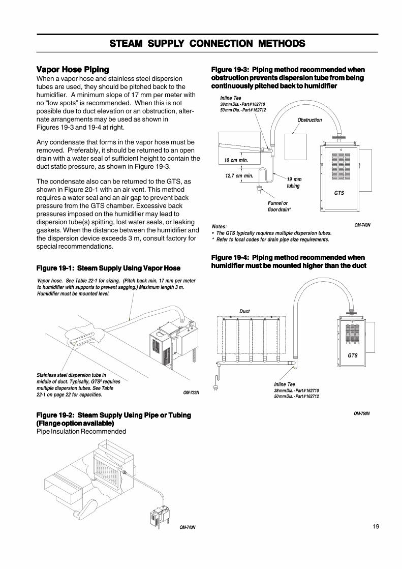
Vapor Hose PipingVapor Hose PipingVapor Hose PipingVapor Hose PipingVapor Hose PipingWhen a vapor hose and stainless steel dispersiontubes are used, they should be pitched back to thehumidifier. A minimum slope of 17 mm per meter withno “low spots” is recommended. When this is notpossible due to duct elevation or an obstruction, alter-nate arrangements may be used as shown inFigures 19-3 and 19-4 at right.
Any condensate that forms in the vapor hose must beremoved. Preferably, it should be returned to an opendrain with a water seal of sufficient height to contain theduct static pressure, as shown in Figure 19-3.
The condensate also can be returned to the GTS, asshown in Figure 20-1 with an air vent. This methodrequires a water seal and an air gap to prevent backpressure from the GTS chamber. Excessive backpressures imposed on the humidifier may lead todispersion tube(s) spitting, lost water seals, or leakinggaskets. When the distance between the humidifier andthe dispersion device exceeds 3 m, consult factory forspecial recommendations.
Figure 19-3: Piping method recommended whenFigure 19-3: Piping method recommended whenFigure 19-3: Piping method recommended whenFigure 19-3: Piping method recommended whenFigure 19-3: Piping method recommended whenobstruction prevents dispersion tube from beingobstruction prevents dispersion tube from beingobstruction prevents dispersion tube from beingobstruction prevents dispersion tube from beingobstruction prevents dispersion tube from beingcontinuously pitched back to humidifiercontinuously pitched back to humidifiercontinuously pitched back to humidifiercontinuously pitched back to humidifiercontinuously pitched back to humidifier
OM-749N
Obstruction
19 mmtubing
Funnel orfloor drain*
10 cm min.
12.7 cm min.
Notes:• The GTS typically requires multiple dispersion tubes.* Refer to local codes for drain pipe size requirements.
GTS
Inline Tee38 mm Dia. - Part # 16271050 mm Dia. - Part # 162712
Figure 19-2: Steam Supply Using Pipe or TubingFigure 19-2: Steam Supply Using Pipe or TubingFigure 19-2: Steam Supply Using Pipe or TubingFigure 19-2: Steam Supply Using Pipe or TubingFigure 19-2: Steam Supply Using Pipe or Tubing(Flange option available)(Flange option available)(Flange option available)(Flange option available)(Flange option available)Pipe Insulation Recommended
OM-743N
Figure 19-1: Steam Supply Using Vapor HoseFigure 19-1: Steam Supply Using Vapor HoseFigure 19-1: Steam Supply Using Vapor HoseFigure 19-1: Steam Supply Using Vapor HoseFigure 19-1: Steam Supply Using Vapor Hose
Vapor hose. See Table 22-1 for sizing. (Pitch back min. 17 mm per meterto humidifier with supports to prevent sagging.) Maximum length 3 m.Humidifier must be mounted level.
Stainless steel dispersion tube inmiddle of duct. Typically, GTS® requiresmultiple dispersion tubes. See Table22-1 on page 22 for capacities. OM-733N
Figure 19-4: Piping method recommended whenFigure 19-4: Piping method recommended whenFigure 19-4: Piping method recommended whenFigure 19-4: Piping method recommended whenFigure 19-4: Piping method recommended whenhumidifier must be mounted higher than the ducthumidifier must be mounted higher than the ducthumidifier must be mounted higher than the ducthumidifier must be mounted higher than the ducthumidifier must be mounted higher than the duct
OM-750N
GTS
Duct
Inline Tee38 mm Dia. - Part # 16271050 mm Dia. - Part # 162712
GTSOM(m)-1199.pdf 19 11/17/2009 4:10:05 PM

20
CONDENSACONDENSACONDENSACONDENSACONDENSATE RETURN PIPINGTE RETURN PIPINGTE RETURN PIPINGTE RETURN PIPINGTE RETURN PIPING
ULTRA-SORB® orRAPID-SORB®
127 mm approx. water seal
152 mm minimum
See Table 21-1
20 mm (3/4”NPT/BSP)condensatereturn
GTS®Humidifier
13 mm air vent
Table 20-1
Figure 20-1: Condensate return to humidifier
reifidimuHledoM
emocrevootderiuqerthgieHerusserplanretnireifidimuh
mm
001-STG 503
002-STG 503
003-STG 754
004-STG 754
OM-3010
GTSOM(m)-1199.pdf 20 11/17/2009 4:10:05 PM

21
RAPID-SORBRAPID-SORBRAPID-SORBRAPID-SORBRAPID-SORB® ® ® ® ® ASSEMBLASSEMBLASSEMBLASSEMBLASSEMBLY AND INSTY AND INSTY AND INSTY AND INSTY AND INSTALLAALLAALLAALLAALLATIONTIONTIONTIONTION
Horizontal Duct InstallationHorizontal Duct InstallationHorizontal Duct InstallationHorizontal Duct InstallationHorizontal Duct Installation1. Unpack shipment and verify receipt of allRAPID-SORB® components with packing list. Reportany shortages to the DRI-STEEM factory immediately.
2. Provide necessary access in and around duct work.
3. Locate 25 mm X 38 mm stainless steel channelinside the duct. Hang the channel from the top of theduct, centered between duct side walls, with the twomounting holes provided.
4. If hose cuffs are used, slide cuffs over the open endof each tube. Install a pair of hose clamps on each tube.
5. Note direction of air flow within duct, then arrangeeach dispersion tube so steam will blow perpendicular tothe air flow. Use the hex bolts provided to attach tubesto overhead 25 mm X 38 mm channel. Do not secure. Ifthe header is outside the duct punch-out necessaryclearance holes in the base of the duct to slide disper-sion tubes up from bottom.
6. Choose header location and refer to appropriatesection
a. For a Header Inside the Ducta. For a Header Inside the Ducta. For a Header Inside the Ducta. For a Header Inside the Ducta. For a Header Inside the Duct (See figure 21-1):1. Punch or cut out necessary clearance holes for
RAPID-SORB header. Slide header into theduct, position header and slide the dispersiontube hose cuffs or slip couplings over theheader dispersion tube nipples.
2. Position the header so vertical dispersion tubesare perpendicular to duct and pitch the header tocondensate drain. Secure header to themounting bracket. Use escutcheon plates tosecure header where it enters the duct.
3. Check that the dispersion tubes release steamperpendicular to the air flow. Secure tubes tothe overhead channel. Secure the channel tothe duct, position hose cuffs or slip couplingsover tube and header tube nipples, and secure.
b. For a Header Outside the Ductb. For a Header Outside the Ductb. For a Header Outside the Ductb. For a Header Outside the Ductb. For a Header Outside the Duct (See figure 21-2):1. Position header under dispersion tubes, then
slide hose cuffs or slip couplings over headerdispersion tube nipples.
2. Position the header so dispersion tubes areperpendicular to duct and pitch the header tocondensate drain. Secure dispersion tubes inplace with the tube escutcheon plates provided.
3. Check the position of the tubes for steamrelease perpendicular to the air flow. Securetubes to the overhead channel, and securechannel to the duct. With header pitched tocondensate drain, slip hose cuffs or slipcouplings over tube nipples and secure.
4. Connect a condensate drain to the header,provide the water trap as shown, and run toopen drain, sized according to governing codes.
5. Attach the header steam supply connector tomain header using the hose cuff and clampsprovided, but do not secure.
6. Route the necessary number of vapor hoses orpipes from the humidifier tank, positionconnector to accept the hoses or pipes andsecure.
Note:Note:Note:Note:Note: Refer to page 19 for vapor hose information onrouting and for alternate vapor hose installationmethods.
Figure 21-1Figure 21-1Figure 21-1Figure 21-1Figure 21-1: RAPID-: RAPID-: RAPID-: RAPID-: RAPID-SORB UnitSORB UnitSORB UnitSORB UnitSORB UnitHeader Inside Duct
Figure 21-2:Figure 21-2:Figure 21-2:Figure 21-2:Figure 21-2: RAPID- RAPID- RAPID- RAPID- RAPID-SORB UnitSORB UnitSORB UnitSORB UnitSORB UnitHeader Under Duct
25 mm x 38 mmstainless steelchannel
Nut andbolt
Duct orcasing
OM-101
OM-748N
Dispersion tube
Orificedtubelets
Slipcoupling orhose cuff
Optional companionflange or threadedconnection for hard piping
Condensate drain(DN20)Header
20 mm copperair gap
*Open drain
15 cmmin.
13 cmmin.
Pitch 1 cm per meter
Top of ductor casing
Dispersiontube
Mounting channel
Orificedtubelets
Hexhead
bolt View A-AView A-AView A-AView A-AView A-ASlip coupling or hose cuff
GTShumidifier
Header
*Open drain
Air gap
Condensatedrain, (DN20)20 mm copper
Escutcheonplate
Duct
25 mm x 38 mm stainlesssteel channel (by DRI-STEEM)
* Refer to local codes for drain pipe sizing and maximum temperaturerequirements.
* Refer to local codes for drain pipesizing and maximum temperaturerequirements.
Pitch 1 cm per metertoward drain min.
Hose cuffand clamps
15 cmmin.
13 cmmin.
GTSOM(m)-1199.pdf 21 11/17/2009 4:10:05 PM

22
RAPID-SORBRAPID-SORBRAPID-SORBRAPID-SORBRAPID-SORB® ® ® ® ® ASSEMBLASSEMBLASSEMBLASSEMBLASSEMBLY AND INSTY AND INSTY AND INSTY AND INSTY AND INSTALLAALLAALLAALLAALLATIONTIONTIONTIONTION
ULULULULULTRA-SORBTRA-SORBTRA-SORBTRA-SORBTRA-SORB® ® ® ® ® INSTINSTINSTINSTINSTALLAALLAALLAALLAALLATIONTIONTIONTIONTIONSee the ULTRA-SORB Installation Instructions and Maintenance Operation Manual.
Vertical Duct InstallationVertical Duct InstallationVertical Duct InstallationVertical Duct InstallationVertical Duct InstallationInstall the RAPID-SORB with dispersion tubes and header pitched to condensate drain as shown in figures 22-2,22-3, and 22-4. See “Instructions for Horizontal Duct” for additional information, as applicable.
Figure 22-4: Elevation View Tubewith Drain
Figure 22-2: Plan View
Steamsupply
1 cm permeter pitchminimum
Drain13 cm min.
15 cm min.
Recommended 150 mmper meter pitch
Figure 22-3: Elevation View Tubewithout Drain
Recommended 2 cm permeter pitch
Airflow
DN6 (1/4")
Condensate drain
13 cmmin.
15 cmmin.
DN20 (3/4")coupling
13 cm min.
Open drain
Airflow
OM-700
Piping (byothers)
Vapor hoseCopper or stainless
steel tubing orsteel pipe
Hose I.D.3 m**
developed lengthkg/h
Tubing O.D.6 m**
developed lengthkg/h
38 mm 68 38 mm 64
50 mm 113 50 mm 95
-- -- 76 mm 186
-- -- 102 mm 318
-- -- 127 mm 590
-- -- 152 mm 953
* Based on total pressure drop inpiping/hose of 1245 Pa.
* * For developed length add 50% tomeasured length for pipe fittings.
Note: To minimize loss of humidifiercapacity and efficiency, the tubing/piping should be insulated.
Piping/Hose Sizing from the GTSPiping/Hose Sizing from the GTSPiping/Hose Sizing from the GTSPiping/Hose Sizing from the GTSPiping/Hose Sizing from the GTS® ® ® ® ® to a RAPID-SORB panelto a RAPID-SORB panelto a RAPID-SORB panelto a RAPID-SORB panelto a RAPID-SORB panelTable 22-1: Maximum Steam Carrying Capacity*Table 22-1: Maximum Steam Carrying Capacity*Table 22-1: Maximum Steam Carrying Capacity*Table 22-1: Maximum Steam Carrying Capacity*Table 22-1: Maximum Steam Carrying Capacity*
GTSOM(m)-1199.pdf 22 11/17/2009 4:10:05 PM

23
GTSGTSGTSGTSGTS®®®®® AREA-TYPE HUMIDIFIER AREA-TYPE HUMIDIFIER AREA-TYPE HUMIDIFIER AREA-TYPE HUMIDIFIER AREA-TYPE HUMIDIFIER
AREA-TYPE Humidifier ApplicationInformationThe operating characteristics of AREA-TYPE steamhumidifiers should be considered when selectinghumidifier capacities and choosing mounting loca-tions.
Steam discharge from the humidifier quickly coolsand turns to visible, warm, microscopic drops orparticles of water (fog), which are lighter than air.
Should this fog contact any solid surface (columns,beams, ceiling, pipes, etc.) before it disappears, itmay collect and drip, as water.
The greater the space relative humidity, the higherand farther the “fog” will carry and rise in the spacebefore disappearing.
The table at right states the vertical (rise), horizontal(throw), and width (spread) dimensions that can beexpected with the Area-Type humidifiers.
To avoid steam impingement on surrounding areas,these dimensions should be observed.
Note: The AREA-TYPE fan and brackets are notprovided as a part of the unit and must be orderedseparately by a DRI-STEEM representative. Aftermounting the fan, terminate the wires as specified onthe enclosed wiring diagram.
Note: In order to achieve the distances listed in Table23-1, the fan specifications should be as follows:motor: 230V, 50 Hzblade dia: 45.7 cmflow rate: 2.52m3/second at zero pascals static pressure
Table 23-1 Minimum Distance for Rise,Spread and Throw
Figure 23-1 AREA-TYPE Fan
OM-1093
SpaceTemp.
SpaceRH
GTS100
GTS200
GTS300
GTS400
37kg/h
73kg/h
110kg/h
120kg/h
16 C
30%
Rise 0.9 m 1.8 m 2.1 m 2.4 m
Spread 0.9 m 1.5 m 2.1 m 2.4 m
Throw 2.4 m 3.7 m 4.0 m 4.6 m
40%
Rise 0.9 m 1.8 m 2.4 m 2.7 m
Spread 0.9 m 1.5 m 2.1 m 2.4 m
Throw 2.4 m 3.7 m 4.3 m 4.9 m
50%
Rise 0.9 m 1.8 m 2.4 m 2.7 m
Spread 1.2 m 1.5 m 2.1 m 2.4 m
Throw 2.4 m 3.7 m 4.3 m 4.9 m
21 C
30%
Rise 0.6 m 1.2 m 1.5 m 1.8 m
Spread 0.6 m 1.2 m 1.5 m 1.8 m
Throw 1.8 m 3.0 m 3.4 m 3.7 m
40%
Rise 0.6 m 1.2 m 1.5 m 1.8 m
Spread 0.7 m 1.2 m 1.5 m 1.8 m
Throw 1.8 m 3.4 m 3.7 m 4.0 m
50%
Rise 0.6 m 1.2 m 1.5 m 1.8 m
Spread 0.7 m 1.2 m 1.5 m 1.8 m
Throw 1.8 m 3.4 m 3.7 m 3.7 m
GTSOM(m)-1199.pdf 23 11/17/2009 4:10:05 PM

24
STSTSTSTSTARARARARARTTTTT-UP AND OPERA-UP AND OPERA-UP AND OPERA-UP AND OPERA-UP AND OPERATIONTIONTIONTIONTION
IntroductionIntroductionIntroductionIntroductionIntroductionAfter the system has been properly installed andconnected to gas, electrical, water supplies and con-trols, it may then be started.
Start-up and Checkout ProceduresStart-up and Checkout ProceduresStart-up and Checkout ProceduresStart-up and Checkout ProceduresStart-up and Checkout ProceduresMountingMountingMountingMountingMountingCheck mounting to see that unit is level and securelysupported before filling with water.
Piping (Gas)Piping (Gas)Piping (Gas)Piping (Gas)Piping (Gas)Verify that all field and humidifier gas piping has beentested for leaks. (Soap and water are not recommendednear gas valves.)
Piping (Steam, Drain, Water Supply)Piping (Steam, Drain, Water Supply)Piping (Steam, Drain, Water Supply)Piping (Steam, Drain, Water Supply)Piping (Steam, Drain, Water Supply)Verify that all piping connections have been completedas recommended and that water pressure is available.
ElectricalElectricalElectricalElectricalElectricalVerify that all wiring connections have been made inaccordance with all local codes and the enclosed GTS®
wiring diagram.
ControlsControlsControlsControlsControlsBefore proceeding with the start-up and operation, verifythat all control wiring has been completed as specifiedand required for correct and safe operation of the GTSHumidifier.
For your particular control system, refer to the manualthat was enclosed with the product shipment.
Also see the separate Installation Instructions andMaintenance Operations Manual for the Controls for theGTS and GTS-DI Gas-to-Steam Humidifiers.
Caution: Only qualified personnel shouldCaution: Only qualified personnel shouldCaution: Only qualified personnel shouldCaution: Only qualified personnel shouldCaution: Only qualified personnel shouldperform the start-up procedure.perform the start-up procedure.perform the start-up procedure.perform the start-up procedure.perform the start-up procedure.
Safety SystemsSafety SystemsSafety SystemsSafety SystemsSafety SystemsThe GTS humidifier has a number of systems andsafeguards to ensure proper operation:
• First, when there is a call for humidity, all of thecombustion blowers must start. Each combustionblower sends a signal to the microprocessorrelaying its current speed. If this actual speed isdifferent from the demand speed, the GTS will notoperate.
• The negative pressure gas valves used on the GTSare designed to keep a constant ratio of air and gasthroughout the operating range of the blower. If theflue becomes blocked or the blower fails to run, thegas valve will not pass any gas to the burner andwill shut down the humidifier.
• During operation, the water level in the tank ismonitored by a probe system for standard waterunits and a low water float for DI/RO units. Thesewater monitors tie into the microprocessor in thecontrol cabinet. If the water level ever drops below asafe point, the humidifier is shut down.
• In standard water applications, the water level in thetank is also monitored by a redundant low watersystem that runs independently of the microproces-sor . This system is tied directly into the powersource for the burners. If this system detects a lowwater condition, the humidifier is shut down.
• In addition to monitoring the water level, there is atemperature sensor located near the top of the heatexchanger. If the water level drops too low and boththe main and redundant low water sensors fail todetect it, the temperature sensor will shut thehumidifier down before an unsafe condition occurs.
• For standard water systems, an additional low watersafety system exists. The microprocessor keepstrack of approximately how much water has left thetank in the form of steam. If this total amountexceeds a preset limit without the fill valve beingenergized, a low water condition is assumed and thehumidifier is shut down. Each time the fill valve isenergized, the total amount is reset to zero. (Thissystem is not implemented on a DI/RO humidifierbecause the float valve is not of the electric-solenoid type. On a DI/RO tank, a mechanical fillvalve maintains the proper water level. This fill valveruns independently of the microprocessor. There-fore, there is no way to reset the steam total to zeroas the tank fills.)
GTSOM(m)-1199.pdf 24 11/17/2009 4:10:06 PM

25
For high performance, and to minimize possible equip-ment failure, it is essential that periodic maintenanceand inspections be performed on this appliance. It isreccommended that the following maintenance beperformed at least once every 2000 hours of operation.
GTSGTSGTSGTSGTS®®®®® Standard Model Only Standard Model Only Standard Model Only Standard Model Only Standard Model OnlyUsing softened water will significantly reduce mineralbuildup in the humidifier. When softened water is notavailable, the GTS is designed to deal with waterhardness in one of two ways depending on the degree ofhardness. For light to moderate hardness, using thesurface water skim time feature with annual cleaning isrecommended. For high mineral content water, aperiodic drain and flush through the motorized drainvalve, in addition to the surface water skim time feature,is recommended. The frequency of cleaning will dependon water condition and evaporation load.
The humidifier and piping should be inspected for waterand gas leaks at least annually, all safety devices in thecontrol circuit should be cycled on and off to verify thatthey are functioning.
Seasonally or as RequiredSeasonally or as RequiredSeasonally or as RequiredSeasonally or as RequiredSeasonally or as RequiredCleaning Evaporating ChamberCleaning Evaporating ChamberCleaning Evaporating ChamberCleaning Evaporating ChamberCleaning Evaporating Chamber - Remove thecleanout plate and dispose of any loose scale that hascollected in the bottom of the tank. This should be donebefore the buildup reaches the underside of the heatexchanger.Cleaning Water Level ProbesCleaning Water Level ProbesCleaning Water Level ProbesCleaning Water Level ProbesCleaning Water Level Probes - Disconnect the plugand cable assembly and unscrew the probe holder fromthe GTS unit. The scale will easily flake off from thesensing portion. The sensing portion (bottom 10 mm ofthe probe should be brushed clean with stainless steelwool.Cleaning Low Water Cut-Out ProbeCleaning Low Water Cut-Out ProbeCleaning Low Water Cut-Out ProbeCleaning Low Water Cut-Out ProbeCleaning Low Water Cut-Out ProbeRemove the humidifier cover and inspect the probe rodfor mineral accumulation. The rod comes from the top ofthe tank near the back. The probe should be brushedclean with stainless steel wool.Cleaning Skim Overflow FittingCleaning Skim Overflow FittingCleaning Skim Overflow FittingCleaning Skim Overflow FittingCleaning Skim Overflow Fitting - Loosen deposits witha long tool, such as a screwdriver. Proper skimmerdrainage should be verified by a weekly visual inspec-tion. Water should drain from skimmer drain pipe aftereach fill cycle. (For cleaning piping, disconnect andflush out. If mineral deposits have restricted the flow,replace piping.)Blower MotorBlower MotorBlower MotorBlower MotorBlower Motor - Lubrication port is not provided, there-fore lubrication is not recommended.
MAINTENANCEMAINTENANCEMAINTENANCEMAINTENANCEMAINTENANCE
Remove Dust -Remove Dust -Remove Dust -Remove Dust -Remove Dust - Using a vacuum, remove all dust fromthe areas around the motor and vent fan (s) and thelouvers that provide air to the shrouded area.
Off-season MaintenanceOff-season MaintenanceOff-season MaintenanceOff-season MaintenanceOff-season MaintenanceAfter the humidification season, a complete inspectionand cleaning of the probe control, skimmer, and waterchamber is recommended. After cleaning, the unitshould remain empty until humidification is required.
Adjusting the Surface Skim Bleed-Off QuantityAdjusting the Surface Skim Bleed-Off QuantityAdjusting the Surface Skim Bleed-Off QuantityAdjusting the Surface Skim Bleed-Off QuantityAdjusting the Surface Skim Bleed-Off QuantityThe skim time determines the quantity of waterskimmed with each fill cycle. The skim time is fieldadjustable using the microprocessor.
Each time the GTS refills, it fills to an elevation near thelip of the skim overflow fitting. A portion of the refillwater then flows to drain carrying the minerals floatingon the water with it. This reduces the mineral concentra-tion, thereby reducing the frequency of cleaning needed.
The heated water that flows to drain is a cost ofoperation. Cleaning the humidifier is also an operationalcost. Therefore, it is recommended that the user ob-serve and adjust the skimming quantity. By doing so, abalance between minimizing mineral buildup and con-serving hot water can be achieved.
GTS-DI Model OnlyGTS-DI Model OnlyGTS-DI Model OnlyGTS-DI Model OnlyGTS-DI Model OnlyThe humidifier and piping should be inspected for waterand gas leaks at least annually. Also, all safety devicesin the control cabinet should be cycled on and off toverify that they are functioning.Makeup Water PipingMakeup Water PipingMakeup Water PipingMakeup Water PipingMakeup Water PipingUse cold or hot makeup water. Even though the GTShas an internal 25 mm air gap, some local codes mayrequire a vacuum breaker.Caution:Caution:Caution:Caution:Caution: Minimum water supply pressure is 175 kPa.Cleaning Evaporating ChamberCleaning Evaporating ChamberCleaning Evaporating ChamberCleaning Evaporating ChamberCleaning Evaporating ChamberAs long as mineral-free water is used in the GTS, nocleaning or flushing of the evaporating chamber shouldbe necessary.Blower MotorBlower MotorBlower MotorBlower MotorBlower Motor - Lubrication port is not provided, there-fore lubrication is not recommended.Remove Dust -Remove Dust -Remove Dust -Remove Dust -Remove Dust - Using a vacuum, remove all dust fromthe areas around the motor and vent fan (s) and thelouvers that provide air to the shrouded area.Off-season MaintenanceOff-season MaintenanceOff-season MaintenanceOff-season MaintenanceOff-season MaintenanceAfter the humidification season, inspect floats and waterchamber, drain and rinse. Empty unit.Caution:Caution:Caution:Caution:Caution: Label all areas prior to disconnection whenservicing controls, wiring errors can cause improper anddangerous operation.
CAUTION: When performing maintenance onCAUTION: When performing maintenance onCAUTION: When performing maintenance onCAUTION: When performing maintenance onCAUTION: When performing maintenance onthe GTS, always place main electrical powerthe GTS, always place main electrical powerthe GTS, always place main electrical powerthe GTS, always place main electrical powerthe GTS, always place main electrical powerdisconnect switch in the off position and closedisconnect switch in the off position and closedisconnect switch in the off position and closedisconnect switch in the off position and closedisconnect switch in the off position and closemanual water and gas valves.manual water and gas valves.manual water and gas valves.manual water and gas valves.manual water and gas valves.
GTSOM(m)-1199.pdf 25 11/17/2009 4:10:06 PM

26
MAINTENANCEMAINTENANCEMAINTENANCEMAINTENANCEMAINTENANCE
• Inspect 50 cm return tubes and clean if necessary.• Run thin brush between turbulator and tube wall on all
four sides.• Reinstall burner assemblies and gaskets; vent box
and gasket; all electrical wiring; gas train shroud; andpressure switch connections.
2. Burner: The burner surface is a self cleaningceramic fabric which does not require maintenance.Contact DRI-STEEM regarding any burneradjustments.
3. INSPECTION RECOMMENDATIONS by user every30 days. Appliance system should be inspectedonce a year by a qualified service person.
• Flue passageways external to the appliance suchas vent connector and chimney to be clear andfree of obstructions.
• Vent connector is in place, sloping upward and isphysically sound without holes or excessivecorrosion.
• Physical support of the appliance is soundwithout sagging cracks, gaps between floor standlegs or tank flanges.
• Verify there are no obvious signs of deteriorationof the appliance.
• Burner flame will operate blue or orange in color -up to a 6 cm from the surface of the burner.See figure 27-1.
• See "Cleaning Water Level Probes" and "CleaningLow Water Cut-Out Probe" on page 25.
108 mm (4 1/4") Dia. burner
Flame may appear blue atstart-up, then turn orangeafter heat-up
OM-847
When servicing or repairing this equipment, use onlyDRI-STEEM-approved service replacement parts. Acomplete replacement parts list is on pages 28 and 30.Refer to the rating plate on the unit for complete unitmodel number, serial number and company address.Any substitution of parts or controls not approved byDRI-STEEM will be at owner's risk and will void thewarranty.
Both GTS® and GTS-DIInspecting the Burner Assemblies and HeatExchanger Tubes1. Note: Soot and carbon deposits may indicate a
combustion problem that needs to be corrected.Consult the factory.
This is not regular maintenance, but if the heatexchanger tubes contain carbon deposits, soot orother residue, clean as follows:
• Turn off gas, electrical power, and water supply.• Remove gas train shroud.• Disconnect wiring to blowers, flame sensors, gas
valves, and ignition controllers.• Remove burner assemblies (each assembly is
mounted with four bolts).• Remove vent box.• Use a 15 cm flue brush with a 60 cm extension
and reversible drill. Work brush in and out of allcombustion chambers.
• Remove loose deposits and residue that falls into rearheader with a vacuum cleaner and hose extension.
Figure 26-1: Burner Assembly Flame
GTSOM(m)-1199.pdf 26 11/17/2009 4:10:06 PM

27
REPLAREPLAREPLAREPLAREPLACEMENT PCEMENT PCEMENT PCEMENT PCEMENT PARARARARARTSTSTSTSTS
Figure 27-1: Standard GTS®
OM-1098
GTSOM(m)-1199.pdf 27 11/17/2009 4:10:06 PM

28
Table 28-1: GTS Replacement Parts (STD) (see Figure 27-1 on Page 27)Table 28-1: GTS Replacement Parts (STD) (see Figure 27-1 on Page 27)Table 28-1: GTS Replacement Parts (STD) (see Figure 27-1 on Page 27)Table 28-1: GTS Replacement Parts (STD) (see Figure 27-1 on Page 27)Table 28-1: GTS Replacement Parts (STD) (see Figure 27-1 on Page 27)
ITEM DESCRIPTION PART NUMBER
1 Tank 168000-TAB
2 Heat Exchanger 168001-TAB
3 Gasket, Heat Exchanger 308230-TAB
4 Cover 167742-TAB
5 Gasket, Cover 308230-TAB
6 Cover Knob 700725
7 Flue Box 168005-TAB
8 High Temp RTV 320001
9 Shroud 168008-TAB
10 Shroud Door 128622-TAB
11 Door Lock with Key 700700
12 200K Burner 405800-002
13 Ignitor 405715-001
14 Sight Glass 405720
15 Sight Glass Bracket 128661
16 Flame Rod 405725
17 Gasket, Blower Mounting 308230-007
18 Gasket, Burner Mounting 308230-006
19 Blower 405800-TAB
20 Gas Valve 405800-007
21 Flange, Gas Valve 405800-009
22 Cable, Gas Valve 405800-010
23 Leg 405800-013
24 Temperature Sensor 405760
25 Mounting Plate, Temp Sensor 167402
26 Probe Assembly 406280
27 Gasket, Probe Assembly 309750-003
28 Probe Housing 308500
29 Probe Plug Assembly 406050-004
30 Valve, Electric Drain 505400-001
31 Clean Out Plate 167401
32 Gasket, Clean Out Plate 308230-005
33 Valve, Solenoid Fill 505084
34 Redundant low water electrode 405726-001
TAB = Refer to your specific model number for correct part.A four burner assembly is shown above.
REPLAREPLAREPLAREPLAREPLACEMENT PCEMENT PCEMENT PCEMENT PCEMENT PARARARARARTSTSTSTSTS
GTSOM(m)-1199.pdf 28 11/17/2009 4:10:06 PM

29
REPLAREPLAREPLAREPLAREPLACEMENT PCEMENT PCEMENT PCEMENT PCEMENT PARARARARARTSTSTSTSTS
Figure 29-1: GTS®-DI
OM-1099
GTSOM(m)-1199.pdf 29 11/17/2009 4:10:06 PM

30
Table 30-1: GTSTable 30-1: GTSTable 30-1: GTSTable 30-1: GTSTable 30-1: GTS®®®®®-DI Replacement Parts (see Figure 29-1 on Page 29)-DI Replacement Parts (see Figure 29-1 on Page 29)-DI Replacement Parts (see Figure 29-1 on Page 29)-DI Replacement Parts (see Figure 29-1 on Page 29)-DI Replacement Parts (see Figure 29-1 on Page 29)
ITEM DESCRIPTION PART NUMBER
1 Tank 168000-TAB
2 Heat Exchanger 168001-TAB
3 Gasket, Heat Exchanger 308230-TAB
4 Cover 167742-TAB
5 Gasket, Cover 308230-TAB
6 Cover Knob 700725
7 Flue Box 168005-TAB
8 High Temp RTV 320001
9 Shroud 168008-TAB
10 Shroud Door 128622-TAB
11 Door Lock with Key 700700
12 200K Burner 405800-002
13 Ignitor 405715-001
14 Sight Glass 405720
15 Sight Glass Bracket 128661
16 Flame Rod 405725
17 Gasket, Blowing Mounting 308230-007
18 Gasket, Burner Mounting 308230-006
19 Blower/Gas Valve Assembly 405800-TAB
20 Leg 405800-013
21 Temperature Sensor 405760
22 Mounting Plate, Temp Sensor 128666
23 Low Wate Float Switch 167789
24 Gasket, Low Water Float Switch 309750-003
25 Valve, Manual Drain 505000-001
26 Clean Out Plate 167401
27 Gasket, Clean Out Plate 308230-005
28 Float Valve 505320
TAB = Refer to your specific model number for correct part.
REPLAREPLAREPLAREPLAREPLACEMENT PCEMENT PCEMENT PCEMENT PCEMENT PARARARARARTSTSTSTSTS
GTSOM(m)-1199.pdf 30 11/17/2009 4:10:06 PM

31
WIRING DIAWIRING DIAWIRING DIAWIRING DIAWIRING DIAGRAMGRAMGRAMGRAMGRAM
GTSOM(m)-1199.pdf 31 11/17/2009 4:10:07 PM

32
WIRING DIAWIRING DIAWIRING DIAWIRING DIAWIRING DIAGRAMGRAMGRAMGRAMGRAM
GTSOM(m)-1199.pdf 32 11/17/2009 4:10:07 PM

33
WIRING DIAWIRING DIAWIRING DIAWIRING DIAWIRING DIAGRAMGRAMGRAMGRAMGRAM
GTSOM(m)-1199.pdf 33 11/17/2009 4:10:08 PM

34
WIRING DIAWIRING DIAWIRING DIAWIRING DIAWIRING DIAGRAMGRAMGRAMGRAMGRAM
GTSOM(m)-1199.pdf 34 11/17/2009 4:10:08 PM

35
OPERATING INSTRUCTIONS
TO TURN OFF GAS TO APPLIANCE
FOR YOUR SAFETY READ BEFORE OPERATING
A. This appliance does not have a pilot. It is equippedwith an ignition device which automatically lights theburner. Do not try to light the burner by hand.
B. BEFORE OPERATING smell all around theappliance area for gas. Be sure to smell next to thefloor because some gas is heavier than air and willsettle on the floor.
FOR YOUR SAFETY“WHAT TO DO IF YOU SMELL GAS”
• Do not try to light any appliance.
• Do not touch any electrical switch; do not useany phone in your building.
• Immediately call your gas supplier from aneighbor’s phone. Follow the gas supplier’sinstructions.
• If you cannot reach your gas supplier, callthe fire department.
C. Do not use this appliance if any part has been underwater. Immediately call a qualified gas applianceservice technician to inspect the appliance and toreplace any part of the control system and any gascontrol that has been under water.
1. Set the humidistat to lowest setting.2. Turn off all electric power to the appliance if service
is to be performed.3. Remove control access panel.
1. STOP! Read the safety information above on thislabel.
2. Set the humidistat to lowest setting.3. Turn off all electric power to the appliance.4. This appliance is equipped with an ignition device
that automatically lights the burner. Do not try tolight the burner by hand.
5. Remove control access panel.6. Unplug the black power plug on the gas valve.7. Wait five (5) minutes to clear out any gas. If you
then smell gas, STOP! Follow “B” in the safetyinformation above on this label. If you don’t smellgas, go to the next step.
8. Plug the black power plug back into the gas valve.9. Replace control access panel.10. Turn on all electric power to the appliance.11. Set humidistat to desired setting.12. If the appliance will not operate, follow the
instructions “To Turn Off Gas To Appliance” and callyour service technician or gas supplier.
If you do not follow these instructions exactly, a fire orexplosion may result causing property damage,personal injury or loss of life.
WARNING!!!!!
4. Unplug the black power plug on the gas valve.5. Replace control access panel.
gas valve
gas valvepower plug
GTSOM(m)-1199.pdf 35 11/17/2009 4:10:08 PM

36
MAINTENANCE SERMAINTENANCE SERMAINTENANCE SERMAINTENANCE SERMAINTENANCE SERVICE RECORDVICE RECORDVICE RECORDVICE RECORDVICE RECORD
DATE INSPECTED PERSONNEL OBSERVATION ACTION PERFORMED
GTSOM(m)-1199.pdf 36 11/17/2009 4:10:09 PM

37
NONONONONOTESTESTESTESTES
GTSOM(m)-1199.pdf 37 11/17/2009 4:10:09 PM

38
NONONONONOTESTESTESTESTES
GTSOM(m)-1199.pdf 38 11/17/2009 4:10:09 PM

39
NONONONONOTESTESTESTESTES
GTSOM(m)-1199.pdf 39 11/17/2009 4:10:09 PM

40
TWTWTWTWTWO-YEAR LIMITED O-YEAR LIMITED O-YEAR LIMITED O-YEAR LIMITED O-YEAR LIMITED WWWWWARRANTYARRANTYARRANTYARRANTYARRANTY
DRI-STEEM Humidifier Company (“DRI-STEEM”) warrants to the original user that its products will be freefrom defects in materials and workmanship for a period of two (2) years after installation or twenty-seven (27)months from the date DRI-STEEM ships such product, whichever date is the earlier.
If any DRI-STEEM product is found to be defective in material or workmanship during the applicablewarranty period, DRI-STEEM’s entire liability, and the purchaser’s sole and exclusive remedy, shall bethe repair or replacement of the defective product, or the refund of the purchase price, at DRI-STEEM’selection. DRI-STEEM shall not be liable for any costs or expenses, whether direct or indirect, associated withthe installation, removal or reinstallation of any defective product.
DRI-STEEM’s limited warranty shall not be effective or actionable unless there is compliance with all installa-tion and operating instructions furnished by DRI-STEEM, or if the products have been modified or alteredwithout the written consent of DRI-STEEM, or if such products have been subject to accident, misuse,mishandling, tampering, negligence or improper maintenance. Any warranty claim must be submitted toDRI-STEEM in writing within the stated warranty period.
DRI-STEEM’s limited warranty is made in lieu of, and DRI-STEEM disclaims all other warranties, whetherexpress or implied, including but not limited to any IMPLIED WARRANTY OF MERCHANTABILITY, ANYIMPLIED WARRANTY OF FITNESS FOR A PARTICULAR PURPOSE, any implied warranty arising out of acourse of dealing or of performance, custom or usage of trade.
DRI-STEEM SHALL NOT, UNDER ANY CIRCUMSTANCES BE LIABLE FOR ANY DIRECT, INDIRECT,INCIDENTAL, SPECIAL OR CONSEQUENTIAL DAMAGES (INCLUDING, BUT NOT LIMITED TO, LOSS OFPROFITS, REVENUE OR BUSINESS) OR DAMAGE OR INJURY TO PERSONS OR PROPERTY IN ANYWAY RELATED TO THE MANUFACTURE OR THE USE OF ITS PRODUCTS. The exclusion appliesregardless of whether such damages are sought based on breach of warranty, breach of contract, negligence,strict liability in tort, or any other legal theory, even if DRI-STEEM has notice of the possibilityof such damages.
By purchasing DRI-STEEM’s products, the purchaser agrees to the terms and conditions of this limitedwarranty.
Continuous product improvement is a policy of DRI-STEEM Humidifier Company therefore,product features and specifications are subject to change without notice.
DRI-STEEM, GTS, RAPID-SORB, ULTRA-SORB, VAPOR-LOGIC and VAPOR-LOGIC2 are Registered Trademarks of the DRI-STEEM Humidifier Company.TEFLON is a Registered Trademark of Dupont.
14949 Technology Drive • Eden Prairie, MN 55344Phone: (612) 949-2415 • Fax: (612) 949-2933E-Mail: [email protected] • Web: www.dristeem.comInternational Office:Bell Place, Bell Lane • Syresham, Brackley • NN13 5HP, U.K.Phone: +44 1280 850122Fax: +44 1280 850124E-Mail: [email protected]
Printed on recycled paper. Minimum10% Post Consumer Waste.
Form No. GTSOM(m)-1199 Copyright © 1999 DRI-STEEM Humidifier Company, Inc. Printed in U.S.A.
GTSOM(m)-1199.pdf 40 11/17/2009 4:10:09 PM