read this owner’s manual replacements are available from ... · portable davit cranes important:...
TRANSCRIPT

Read this Owner’s Manual thoroughly before operating the equipment. Keep it with the equipment at all times. Replacements are available from Thern, Inc., PO Box 347, Winona, MN 55987, 507-454-2996.www.thern.com
Owner’s ManualFor 5110 and 5124 Series Portable Davit Cranes
IMPORTANT: Please record product information on page 2. This information is required when calling the factory for service.
A8084F-1216
ORIGINAL TEXT

Owner's Manual for Thern 5110 and 5124 Series Portable Davit Cranespage 2
A8084F-1216
Two-Year Limited WarrantyThern, Inc. warrants its products against defects in material or workmanship for two years from the date of purchase by the original using buyer, or if this date cannot be established, the date the product was sold by Thern, Inc. to the dealer. To make a claim under this warranty, contact the factory for an RGA number. The product must be returned, prepaid, directly to Thern, Inc., 5712 Industrial Park Road, Winona, Minnesota 55987. The following information must accompany the product: the RGA number, the date of purchase, the description of the claimed defect, and a com-plete explanation of the circumstances involved. If the product is found to be defective, it will be repaired or replaced free of charge, and Thern, Inc. will reimburse the shipping cost within the contiguous USA.
This warranty does not cover any damage due to accident, misuse, abuse, or negligence. Any alteration, repair or modification of the product outside the Thern, Inc. factory shall void this warranty. This warranty does not cover any costs for removal of our product, downtime, or any other incidental or consequential costs or damages resulting from the claimed defects. This warranty does not cover brake discs, wire rope or other wear components, as their life is subject to use conditions which vary between applications.
FACTORY AUTHORIZED REPAIR OR REPLACEMENT AS PROVIDED UNDER THIS WARRANTY IS THE EXCLUSIVE REMEDY TO THE CONSUMER. THERN, INC. SHALL NOT BE LIABLE FOR ANY INCIDEN-TAL OR CONSEQUENTIAL DAMAGES FOR BREACH OF ANY EXPRESS OR IMPLIED WARRANTY ON THIS PRODUCT. EXCEPT TO THE EXTENT PROHIBITED BY APPLICABLE LAW, ANY IMPLIED WAR-RANTY OF MERCHANTABILITY OR FITNESS FOR A PARTICULAR PURPOSE ON THIS PRODUCT IS LIMITED IN DURATION TO THE DURATION OF THIS WARRANTY.
Some states do not allow the exclusion or limitation of incidental or consequential damages, or allow limitations on how long an implied warranty lasts, so the above limitation or exclusion may not apply to you. This warranty gives you specific legal rights, and you may also have other rights which vary from state to state.
Note: Thern, Inc. reserves the right to change the design or discontinue the production of any product without prior notice.
About This ManualThe Occupational Safety and Health Act of 1970 states that it is the employer’s responsibility to provide a workplace free of hazard. To this end, all equipment should be installed, operated, and maintained in compliance with applicable trade, industrial, federal, state, and local regulations. It is the equipment owner's respon-sibility to obtain copies of these regulations and to determine the suitability of the equipment to its intended use.
This Owner’s Manual, and warning labels attached to the equipment, are to serve as guidelines for hazard-free installation, operation, and maintenance. They should not be understood to prepare you for every possible situation.
The information contained in this manual is applicable only to the Thern 5110 and 5124 Series Portable Davit Cranes. Do not use this manual as a source of infor-mation for any other equipment.
The following symbols are used for emphasis throughout this manual:
Failure to follow ‘WARNING!’ instructions may result in equipment damage, property damage, and/or serious personal injury.
Failure to follow ‘CAUTION!’ instructions may result in equipment damage, property damage, and/or minor personal injury.
Important!
Failure to follow ‘important!’ instructions may result in poor performance of the equipment.
Please record the following:Date Purchased:
Crane Model No.:
Crane Serial No.:
If sold with a winch:Winch Model No.:
Winch Serial No.:
This information is required when calling the factory for service.
Owner's Manual for Thern 5110 and 5124 Series Portable Davit Cranes page 3
A8084F-1216
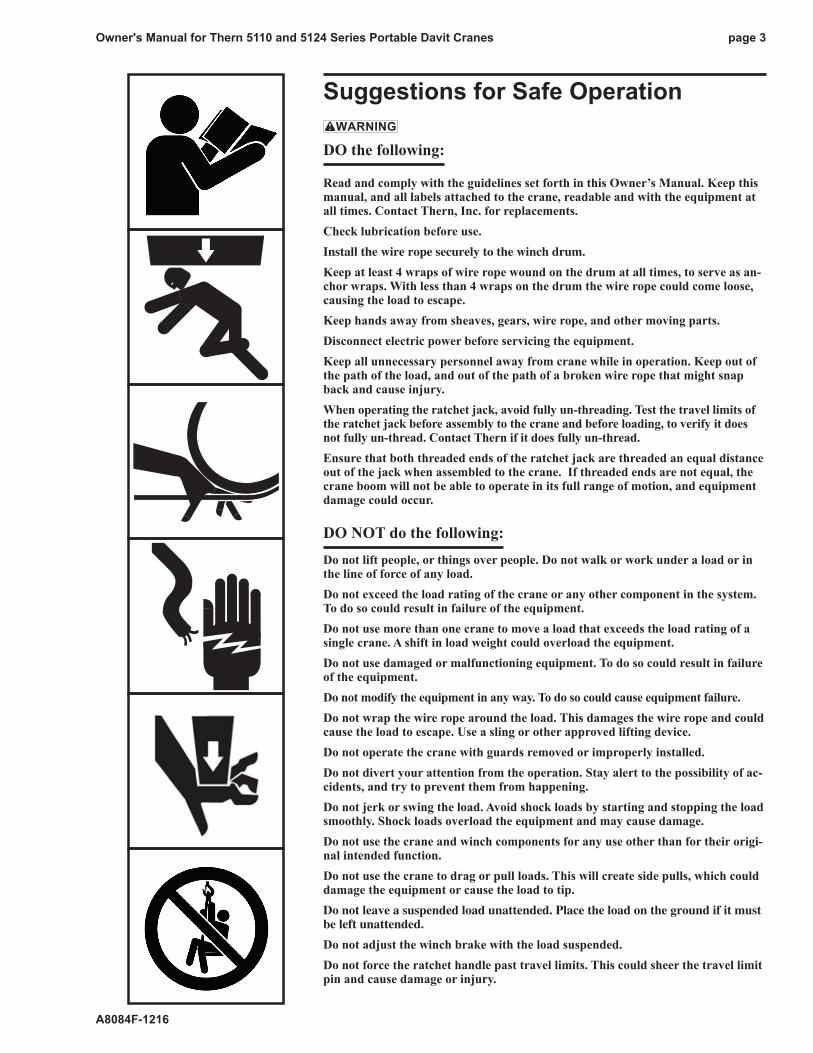
Suggestions for Safe Operation
DO the following:
Read and comply with the guidelines set forth in this Owner’s Manual. Keep this manual, and all labels attached to the crane, readable and with the equipment at all times. Contact Thern, Inc. for replacements.Check lubrication before use.Install the wire rope securely to the winch drum.
Keep at least 4 wraps of wire rope wound on the drum at all times, to serve as an-chor wraps. With less than 4 wraps on the drum the wire rope could come loose, causing the load to escape.Keep hands away from sheaves, gears, wire rope, and other moving parts.Disconnect electric power before servicing the equipment.Keep all unnecessary personnel away from crane while in operation. Keep out of the path of the load, and out of the path of a broken wire rope that might snap back and cause injury.When operating the ratchet jack, avoid fully un-threading. Test the travel limits of the ratchet jack before assembly to the crane and before loading, to verify it does not fully un-thread. Contact Thern if it does fully un-thread.Ensure that both threaded ends of the ratchet jack are threaded an equal distance out of the jack when assembled to the crane. If threaded ends are not equal, the crane boom will not be able to operate in its full range of motion, and equipment damage could occur.
DO NOT do the following:Do not lift people, or things over people. Do not walk or work under a load or in the line of force of any load.Do not exceed the load rating of the crane or any other component in the system. To do so could result in failure of the equipment.Do not use more than one crane to move a load that exceeds the load rating of a single crane. A shift in load weight could overload the equipment.Do not use damaged or malfunctioning equipment. To do so could result in failure of the equipment.Do not modify the equipment in any way. To do so could cause equipment failure. Do not wrap the wire rope around the load. This damages the wire rope and could cause the load to escape. Use a sling or other approved lifting device.Do not operate the crane with guards removed or improperly installed.Do not divert your attention from the operation. Stay alert to the possibility of ac-cidents, and try to prevent them from happening. Do not jerk or swing the load. Avoid shock loads by starting and stopping the load smoothly. Shock loads overload the equipment and may cause damage.Do not use the crane and winch components for any use other than for their origi-nal intended function.Do not use the crane to drag or pull loads. This will create side pulls, which could damage the equipment or cause the load to tip.Do not leave a suspended load unattended. Place the load on the ground if it must be left unattended.
Do not adjust the winch brake with the load suspended.Do not force the ratchet handle past travel limits. This could sheer the travel limit pin and cause damage or injury.

Owner's Manual for Thern 5110 and 5124 Series Portable Davit Cranespage 4
A8084F-1216
Important!
• A qualified professional should inspect or design the founda-tion to insure that it will provide adequate support.
• Locate the crane so it will be vis-ible during the entire operation.
1.1 Installing the Crane
Do not install the crane in an area defined as hazardous by the National Electric Code, unless installation in such an area has been thoroughly approved.
Do not install the crane near corrosive chemicals, flammable materials, ex-plosives, or other elements that may damage the crane or injure the operator. Adequately protect the crane and the operator from such elements.
Position the crane so the operator can stand clear of the load, and out of the path of a broken wire rope that could snap back and cause injury.
Attach the crane to a rigid and level foundation that will support the crane and its load under all load conditions, including shock loading.
1.1.1 CONSULT APPLICABLE CODES AND REGULATIONS for specific rules on installing the equipment.
1.1.2 LOCATE THE CRANE in an area clear of traffic and obstacles that could interfere with operation. Make sure the crane is accessible for maintenance and operation.
1.1.3 INSTALL THE CRANE on a level surface. An uneven surface may cause the boom to rotate in the direction the mast is leaning.
1.1.4 FASTEN THE BASE securely to the foundation to withstand applicable overturning moments and mounting bolt reaction. See Table 1.
a FOR STANDARD PRODUCTS referred to in this manual, use 5/8 - inch coarse thread fasteners, grade 5 or better. Torque for Grade 5 fasteners with-out lubrication is 150 ft lb. Make sure mounting holes are secured to a solid foundation able to support the crane and the load under all conditions with design factors based on accepted engineering practices.
b NON-STANDARD PRODUCTS that vary from the original design may have different fastening requirements. Contact a structural engineer or Thern, Inc. for this information.
TO COMPLY WITH LOCAL CODES, CONTACT A QUALIFIED PROFES-SIONAL TO OBTAIN PROPER STRUCTURE OR FOUNDATION SPECIFICA-TIONS FOR THE MOUNTING OF THERN PRODUCTS.
Pedestal Wall-Mount Base Only Base OnlyCrane Mast Suggested Axial Force1 Axial Force1 Shear Force Model Moment Bolt Size Per Bolt Per Bolt5110 37,817 in-lb 5/8 inch 1,844 lb 1,304 lb 1,177 lb
5124 95,236 in-lb 5/8 inch 4,644 lb 3,284 lb 2,781 lb1 Force in tension
Table 1 – Crane Reactions
Owner's Manual for Thern 5110 and 5124 Series Portable Davit Cranes page 5
A8084F-1216
Important!
• Inspect the crane during assembly according to the Instructions for Periodic Inspection. This will give you a record of the condition of the crane with which to com-pare future inspections.
• Save all boxes and crates that the crane was shipped in, use them again if you need to repackage the crane.
• Contact the factory immediately if any parts are missing or damaged.
• Do not overtighten fasteners, this may strip threads or cause dam-age to other parts.
1.2 Assembling the Crane
When installing the ratchet jack, support the end of the boom so the boom does not fall and the ratchet jack does not swing up causing damage or injury.
When installing the boom extension, hold the boom extension securely so it does not slide abruptly in or out of the boom causing damage or injury.
1.2.1 STUDY PARTS DRAWINGS to understand how the crane is assembled. See pages 18-22.
1.2.2 LUBRICATE PINS and other components prior to assembly. See Section 3.3 Lubricating the Crane.
1.2.3 INSTALL THE BASE and then assemble the crane in the following order.
a INSTALL THE MAST in the base. Move the mast side to side to make sure the bottom of the mast properly seats on the pin in the bottom of the base.
b FASTEN THE BOOM to the mast using the clevis pin and lynch pin provided. Make sure the boom is positioned correctly, with the carrying handles lo-cated on the same side as the handles on the mast.
c BEFORE INSTALLING THE RATCHET jACk Ensure that both threaded ends of the ratchet jack are threaded an equal distance out of the jack when assembled to the crane. If threaded ends are not equal, the crane boom will not be able to operate in its full range of motion, and equipment damage could occur.
d INSTALL THE RATCHET jACk by fastening one end of the ratchet jack to the ears on the boom with the clevis and lynch pin provided. Carefully pivot the boom up until the other end of the ratchet jack aligns with the ears on the mast, and secure the ratchet jack to the mast using the clevis pin and lynch pin provided.
e ADjUST THE BOOM with the ratchet jack so the boom is slightly above the lowest boom angle. See Figures 4a and 4b. Do not lower boom below the lowest point, or the boom could fall and may result in the load escaping.
f SLIDE THE BOOM EXTENSION into the boom, and secure in place with the clevis pin and lynch pin provided. Make sure the boom extension is positioned correctly with the boom ears positioned up. See assembly drawings.
g POSITION THE SHEAVE between the ears on the boom extension, and fasten in place with the clevis pin and cotter pin provided.
h INSTALL THE CLEVIS PIN in the holes located above the sheave at the end of the boom. Secure in place with the hair cotter pin provided.
i INSTALL THE HANDLE on the lower end of the boom, using the clevis pin and lynch pin provided.
1.2.4 FASTEN THE WINCH to the mounting plate on the boom using the fasteners provid-ed. On some models you will need to use the winch adapter plate and fasteners pro-vided to fasten the winch to the crane. Make sure the winch is positioned correctly with the winch drum facing forward toward the boom extension.
1.2.5 INSTALL THE WINCH HANDLE on hand winches, or connect electric current on power winches. Refer to instructions in the Winch Owner’s Manual.
1.2.6 INSTALL THE WIRE ROPE. Use wire rope assemblies in the length specified on page 23.
a PASS THE WIRE ROPE over the sheave at the end of the boom.
b ANCHOR THE WIRE ROPE to the winch drum and wind 4 wraps of wire rope onto the drum to act as anchor wraps. Refer to the instructions in the Winch Owner’s Manual.
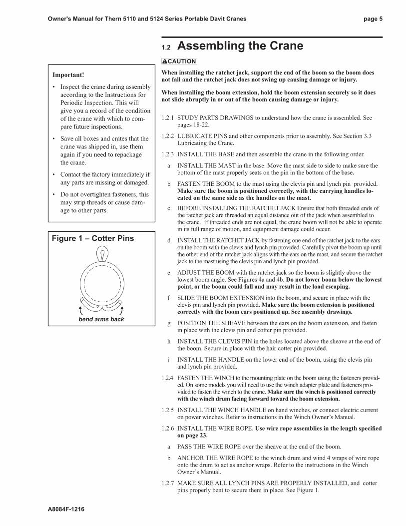
1.2.7 MAkE SURE ALL LYNCH PINS ARE PROPERLY INSTALLED, and cotter pins properly bent to secure them in place. See Figure 1.
Figure 1 – Cotter Pins
bend arms back

Owner's Manual for Thern 5110 and 5124 Series Portable Davit Cranespage 6
A8084F-1216
2.1 General Theory of Operation2.1.1 THE INTENDED USE of this machinery is to lift and lower loads of its
rated capacity or less. It is not for lifting people or things over people.
2.1.2 THE FORCE REQUIRED to lift the load must not exceed the load rating of the crane. Consider the total force required to lift the load, not the weight of the load.
2.1.3 THIS EQUIPMENT CAN develop forces that will exceed the load rating. It is the responsibility of the equipment user to limit the size of the load. Inspect the equipment regularly for damage according to the instructions contained in this manual.
2.1.4 PERFORMANCE RATINGS of the equipment are affected by the position of the boom, the amount of wire rope you use and whether you use a single or two part line. Two-part line not available on the 5110 Series. See the Per-formance Characteristics Tables on page 23.
a LOAD RATING represents the maximum force that can be placed on new equipment. Load ratings are assigned values for specific boom positions, wire rope lengths, and rigging configurations (single or two part line). Crane load ratings decrease as you extend the boom, and increase with two-part line. Two-part line not available on 5110 Series. See the Perfor-mance Characteristics Tables page 23.
b LIFT varies with the position of the boom, the length of the wire rope, and the rigging configuration (single or two part line). Two-part line not available on the 5110 Series.
c REACH varies with the position of the boom.
2.1.5 DUTY RATINGS refer to the type of use the equipment is subject to. Con-sider the following when determining duty rating.
a ENVIRONMENT: harsh environments include hot, cold, dirty, wet, corro-sive, or explosive surroundings. Protect the equipment from harsh envi-ronments when possible.
b MAINTENANCE: poor maintenance, meaning poor cleaning, lubrication, or inspection, leads to poor operation and possible damage of the equipment. Minimize poor maintenance by carefully following the instructions con-tained in this manual.
c LOADING: severe loading includes shock loading and lifting loads that exceed the load rating of the equipment. Avoid shock loads, and do not exceed the load rating of the equipment.
d FREQUENCY OF OPERATION: frequent or lengthy operations increase wear and shorten the life span of gears, bearings, sheaves, and other components. Increase maintenance of the equipment if used in frequent operations.
2.1.6 AIRBORNE NOISE EMISSIONS vary depending on load and the type of winch being used. Standard configurations do not typically exceed a sound pressure level of 80dB(A) at workstations.
2.1.7 VIBRATION LEVELS vary depending on load and type of winch being used. Standard configurations do not typically exceed vibration levels of 2.5 m/s2.
CONTACT THE FACTORY FOR MORE INFORMATION.
Important!
• Limit nonuniform winding by keeping tension on the wire rope.
• It is your responsibility to detect and account for different factors affecting the condition and performance of the equipment.
Owner's Manual for Thern 5110 and 5124 Series Portable Davit Cranes page 7
A8084F-1216
2.2 Preparing for Operation
When operating the ratchet jack, avoid fully un-threading. Test the travel limits of the ratchet jack before assembly to the crane and before loading, to verify it does not fully un-thread. Contact Thern if it does fully un-thread.
Do not force the ratchet handle past travel limits. This could shear the travel limit pin and cause damage or injury.
When adjusting boom length, set the boom angle just above the lowest angle and hold the boom extension securely so it does not slide abruptly in or out of the boom causing damage or injury. See Figures 4a and 4b.
When adjusting the boom angle, raise the rotation handle with one hand and operate the ratchet jack with the other to avoid jamming the handles and causing damage or injury.
2.2.1 CONSIDER THE OPERATION. Do not begin until you are sure you can perform the entire operation without hazard.
2.2.2 INSPECT ALL COMPONENTS of the system.
a INSPECT THE CRANE and other equipment according to the Instructions for Frequent Inspection.
b INSPECT THE WINCH according to the instructions in the Winch Owner’s Manual.
c OPERATORS must be in good health, alert, thoroughly trained in operat-ing the equipment, and properly clothed (hard hat, safety shoes and safety glasses, no loose clothing).
d THE LOAD must be clear of other objects and free to move. Make sure the load will not tip, spin, roll away, or in any way move uncontrollably.
2.2.3 kNOW YOUR LOAD and make sure you do not exceed the load rating of the crane or any other equipment in the system.
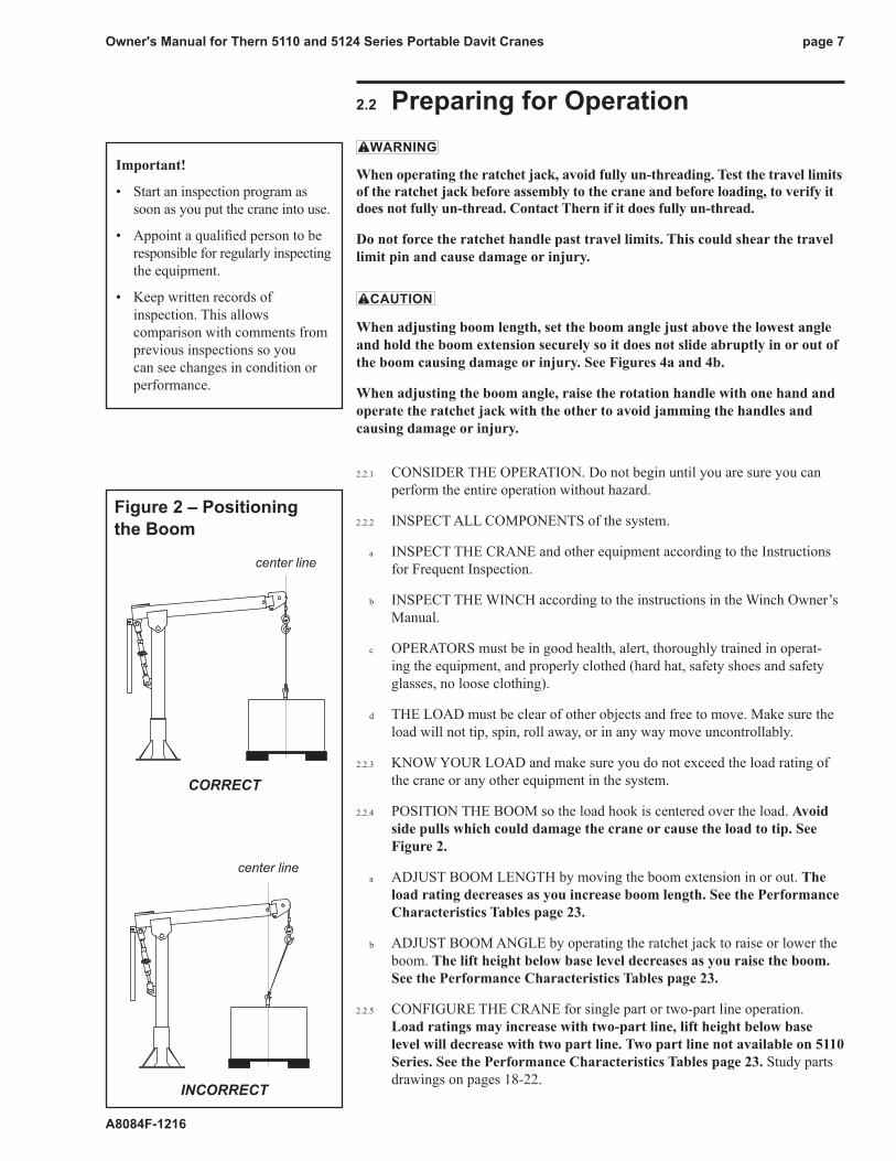
2.2.4 POSITION THE BOOM so the load hook is centered over the load. Avoid side pulls which could damage the crane or cause the load to tip. See Figure 2.
a ADjUST BOOM LENGTH by moving the boom extension in or out. The load rating decreases as you increase boom length. See the Performance Characteristics Tables page 23.
b ADjUST BOOM ANGLE by operating the ratchet jack to raise or lower the boom. The lift height below base level decreases as you raise the boom. See the Performance Characteristics Tables page 23.
2.2.5 CONFIGURE THE CRANE for single part or two-part line operation. Load ratings may increase with two-part line, lift height below base level will decrease with two part line. Two part line not available on 5110 Series. See the Performance Characteristics Tables page 23. Study parts drawings on pages 18-22.
Figure 2 – Positioning the Boom
center line
center line
correct
incorrect
Important!
• Start an inspection program as soon as you put the crane into use.
• Appoint a qualified person to be responsible for regularly inspecting the equipment.
• Keep written records of inspection. This allows comparison with comments from previous inspections so you can see changes in condition or performance.

Owner's Manual for Thern 5110 and 5124 Series Portable Davit Cranespage 8
A8084F-1216
2.3 Attaching the Load
Do not wrap the wire rope around the load. This damages the wire rope and could cause the load to escape. Use a sling or other approved lifting device.
2.3.1 CLEAR OBjECTS from the path of the load so you can move it freely and observe it at all times during the operation.
2.3.2 MAkE SURE THE WIRE ROPE is not twisted. A twisted wire rope could cause the load to spin when it is raised off the ground.
2.3.3 ATTACH THE LOAD using a nylon sling, or other approved lifting device. Follow the recommendations of the sling manufacturer.
a SEAT THE SLING in the saddle of the hook with the hook latch completely closed. See Figure 3.
b CENTER THE LOAD on the hook so it will remain balanced and not tip or rotate to one side.
2.4 Moving the Load
When operating the ratchet jack, avoid fully un-threading. Test the travel limits of the ratchet jack before assembly to the crane and before loading, to verify it does not fully un-thread. Contact Thern if it does fully un-thread.
Do not force the ratchet handle past travel limits. This could shear the travel limit pin and cause damage or injury
2.4.1 MOVE THE LOAD slowly and smoothly, only a small distance at first. Make sure the load is balanced and securely attached before continuing.
2.4.2 OPERATE THE WINCH to raise or lower the load. Refer to the instructions in the Winch Owner’s Manual.
2.4.3 OBSERVE THE WIRE ROPE as it winds onto the drum. If it becomes loose, uneven, or overlapped, stop the operation and rewind the wire rope before continuing. Continued operation with overlapped or uneven wire rope can damage the wire rope and shorten its life.
2.4.4 OPERATE THE RATCHET jACk if necessary, to adjust the angle of the boom to keep the sheave centered over the load.
2.4.5 ROTATE THE BOOM to move the load side-to-side.
a ROTATE THE BOOM slowly and smoothly to avoid swinging the load or causing shock loads. Do not jam the boom against other objects.
b USE THE HANDLE to rotate the boom. Do not push or pull the load or the wire rope to rotate the boom.
Figure 3 – Attaching Load
latch closed tight against hook
sling seated in saddle of hook
Important!
• Obey a stop signal from anyone.
• Maintain tension on the wire rope to keep it tightly and evenly wound on the drum.
• If the crane and load are not visible during the entire operation, get help from another person.
• Appoint a supervisor if more than one person is involved in the operation. This will reduce confusion and increase safety.
• When lifting a load, use a tag line to keep the load from swinging or twisting, while keeping yourself away from the load.
Owner's Manual for Thern 5110 and 5124 Series Portable Davit Cranes page 9
A8084F-1216
3.1 Cleaning the Crane Clean the crane to remove dirt and help prevent rust and corrosion.
3.1.1 CLEAN THE CRANE every six months or whenever it is dirty.
a WIPE ALL EQUIPMENT to remove dirt and grease.
b LEAVE A LIGHT FILM of oil on all surfaces to protect against rust and corrosion.
c WIPE OFF excessive amounts of oil to avoid the accumulation of dirt.
3.1.2 REMOVE UNNECESSARY OBjECTS from the area surrounding the crane.
Important!
Increase the frequency of maintenance procedures if the crane is:
• Operated for long periods.
• Used to lift heavy loads.
• Operated in wet, dirty, hot, or cold surroundings.
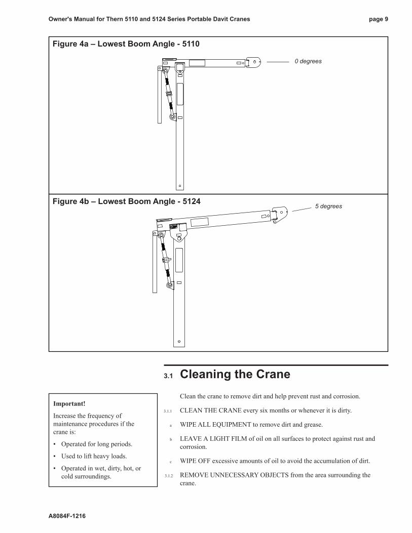
Figure 4a – Lowest Boom Angle - 5110
Figure 4b – Lowest Boom Angle - 5124
0 degrees
5 degrees
Owner's Manual for Thern 5110 and 5124 Series Portable Davit Cranespage 10
A8084F-1216
3.2 Disassembling the Crane
When removing the boom extension, hold the boom extension securely so it does not slide abruptly in or out of the boom causing damage or injury.
When removing the ratchet jack, support the end of the boom so the boom does not fall and the ratchet jack does not swing up causing damage or injury.
3.2.1 REMOVE ANY ATTACHED LOAD from the wire rope.
3.2.2 REMOVE THE WIRE ROPE
a REMOVE THE ROPE kEEPER CLEVIS PIN located at the end of the boom.
b UNWIND THE ROPE from the winch drum and release the anchor.
c REPLACE THE ROPE kEEPER CLEVIS PIN
3.2.3 REMOVE THE WINCH HANDLE on hand winches, or disconnect electric current on power winches. Refer to instructions in the Winch Owner’s Manual.
3.2.4 REMOVE THE WINCH from the mounting plate.
a SECURE THE WINCH to prevent it from falling off when the fasteners are loosened.
b LOOSEN AND REMOVE the fasteners.
3.2.5 REMOVE THE ROTATION HANDLE from the back of the boom. (NOTE: Remove the rotation handle first before the ratchet jack to avoid it swinging up if the boom should fall when the ratchet jack is released.)
a REMOVE THE LYNCH PIN and clevis pin and remove the handle.
b REPLACE THE CLEVIS PIN and lynch pin.
3.2.6 REMOVE THE BOOM EXTENSION.
a ADjUST THE BOOM ANGLE using the ratchet jack, so the boom is just slightly above horizontal.
b SECURE THE BOOM EXTENSION then remove the lynch pin and clevis pin securing the boom extension to the boom.
c CAREFULLY PULL THE BOOM EXTENSION out of the boom, then reinstall the clevis pin and lynch pin in the boom.
3.2.7 REMOVE THE RATCHET jACk.
a SECURE THE BOOM to prevent it from falling when the ratchet jack is released.
b DISCONNECT THE RATCHET JACK at the mast ears (bottom) by removing the lynch pin and clevis pin and slowly lower the boom until it is resting against the mast. Be careful that the ratchet jack does not swing up and cause injury.

Owner's Manual for Thern 5110 and 5124 Series Portable Davit Cranes page 11
A8084F-1216
Important!
• Make sure lubricant has a temperature rating appropriate for the ambient temperatures of the operation.
c REMOVE THE PINS AT THE BOOM (top) to disconnect the ratchet jack from the crane. Hold onto the ratchet jack to prevent it from falling away.
d RECONNECT the clevis pins to the boom and mast with the appropriate lynch pins.
3.2.8 DISCONNECT THE BOOM from the mast.
a SECURE THE BOOM to prevent it from falling away when the pins are removed.
b REMOVE THE LYNCH PIN AND CLEVIS PIN and carefully remove the boom.
c REPLACE the clevis pin and lynch pin in the mast.
3.2.9 REMOVE THE MAST FROM THE BASE, by lifting it out of the base.
TO REASSEMBLE THE CRANE, SEE ASSEMBLING THE CRANE, SECTION 1.2.
3.3 Lubricating the CraneLubricate the crane properly to help protect it from wear and rust. Read the following instructions carefully.
3.3.1 LUBRICATE ALL PINS before installation and at least every 3 months. Use a grease brush to apply a light film of NLGI #2 grease to all pins.
3.3.2 LUBRICATE THE MAST BEARING before installation and at least every 3 months. Use a grease brush to apply a film of NLGI #2 grease to both inside and outside surfaces.
3.3.3 LUBRICATE THE PIN BUSHING located on the bottom of the mast before installation and at least every 3 months. Use a grease brush to apply a film of NLGI #2 grease to the bushing.
3.3.4 LUBRICATE THE RATCHET jACk before installation and at least every 3 months. Use a grease gun to apply an NLGI #2 grease to the grease fittings on the ratchet jack until excess grease can be seen.
3.3.5 LUBRICATE THE WINCH. Refer to the Winch Owner’s Manual for instructions.
3.3.6 LUBRICATE THE WIRE ROPE and other equipment by following the manufacturers recommendations.

Owner's Manual for Thern 5110 and 5124 Series Portable Davit Cranespage 12
A8084F-1216
3.4 Inspecting the Equipment
Do not use damaged or malfunctioning equipment. Place an “OUT OF ORDER” sign on the crane. Do not use the crane until the sign is removed by a qualified maintenance person who has completely corrected the problem.
Inspect the crane to detect signs of damage or poor operation before they become hazardous. See Table 2 Inspection Checklist.
3.4.1 CONSULT APPLICABLE CODES AND REGULATIONS for specific rules on inspecting the crane and other equipment.
3.4.2 REFER TO THE WINCH OWNER’S MANUAL for information regarding winch inspection.
3.4.3 Instructions for Frequent Inspection
a VISUALLY INSPECT the entire crane and all other equipment involved in the operation.
• Check all equipment for cracks, dents, bending, rust, wear, corrosion and other damage.
• Make sure the wire rope is installed correctly and anchored securely.
• Make sure the entire crane is properly lubricated.
• Make sure all fasteners are tight and secure.
• Make sure mounting fasteners are tightened securely.
• Check the ratchet jack for signs of leakage or damage, and make sure it operates smoothly to raise and lower the boom.
• Make sure the foundation is in good condition, and capable of supporting the crane and its load under all load conditions.
b TEST CRANE PERFORMANCE by operating the crane with a load not exceeding the load rating.
• Listen for unusual noises, and look for signs of damage as you operate the crane.
• Make sure the wire rope winds evenly and tightly onto the drum. If it is loose or uneven, rewind it before continuing.
• Make sure the load moves smoothly, without hesitation or strain.
• On hand operated models, make sure the winch handle rotates freely in both directions.
• On power operated models, make sure the winch responds to the control device. It must rotate as shown on the control labels, and it must turn off when you release the control.
• Make sure the boom rotates freely when you push the handle, and remains stationary when you release it.
• Check the brake. Raise the load, then lower it and stop it a few feet off the ground. If the load continues to coast or creep under normal operating conditions, the brake may be worn and in need of repair or replacement. Contact the factory.
Completely correct all problems before continuing. Use the Troubleshooting Chart to help determine the cause of certain problems. See Table 3.
Important!
• Start an inspection program as soon as you put the crane into use.
• Appoint a qualified person to be responsible for regularly inspecting the equipment.
• Keep written records of inspection. This allows comparison with comments from previous inspections so you can see changes in condition or performance.
Perform frequent inspections:
• Before each operation.
• Every 3 hours during operation.
• Whenever you notice signs of damage or poor operation.
Frequent Wire Rope Inspection:
• Use ASME B30.7 as a guideline for rope inspection, replacement and maintenance.
• Check the wire rope, end connections and end fittings for corrosion, kinking, bending, crushing, birdcaging or other signs of damage.
• Check the number, distribution and type of visible broken wires. See paragraph 3.3.4 b and Figure 5.
• Check the wire rope for reduction of rope diameter from loss of core support, or wear of outside wires. See Figure 7.
• Take extra care when inspecting sections of rapid deterioration such as sections in contact with saddles, sheaves, repetitive pickup points, crossover points and end connections.

Owner's Manual for Thern 5110 and 5124 Series Portable Davit Cranes page 13
A8084F-1216
Table 2 – Inspection Checklist damages problemsgeneral finishweathered,flaking,otherwisedamaged equipmentnotproperlylubricated
partscracked,bent,rusted,worn,otherwisedamaged unusualnoises,othersignsofmalfunction
foundation loose,unstable,otherwisedamaged notlevel-boomswerves
fasteners strippedthreads,bent,worn,otherwisedamaged loose,nottightenedtothepropertorque
boom assembly holesworn,distorted,orotherwisedamaged doesnotrotatefreely
winch assembly gears,bearings,andotherpartsworn,otherwisedamaged winchjerksorhesitatesunderload
brakecorroded,cracked,worn,otherwisedamaged brakedoesnotoperateproperly
sheaves holesworn,distorted,orotherwisedamaged doesnotrotatefreely
wire rope bent,crushed,otherwisedamaged wireropelooselyorunevenlywound
brokenwires,seeFigure5
replaceifmorethan6wiresinonelay, numberperstrand=
or3wiresinonestrandinonelay,arebroken numberperlay=
diameterreduced,seeFigure7
replaceifdiameterisexcessivelyworn diameter=
end connections corroded,rusted,worn,otherwisedamaged notsecurelyattached
load hook twisted,bent,worn,otherwisedamaged,seeFigure6 hooklatchfailstoclosewhenreleased
replaceiftwistis10degreesormore twist=
replaceifthroatwidthis15%largerthannominal throatwidth=
replaceifthicknessis10%lessthannominal thickness=
labels and plates dirty,illegible,otherwisedamaged looselyattachedormissing
comments:
authorized signature: date
checked boxes indicate damage or problem in need of repair

Owner's Manual for Thern 5110 and 5124 Series Portable Davit Cranespage 14
A8084F-1216
twist
throat opening
thickness
Figure 6 – Load Hook Inspection
The wire rope assembly must be replaced if the throat opening is 15% wider than nominal, if the thickness is 10% less than nominal, or if the hook is twisted 10° or more.
Perform periodic inspections:
• Every 6 months.
• Whenever you return the crane to service from storage.
• Whenever you notice damage or poor operation in a frequent inspection.
• Whenever you have, or think you may have, overloaded or shock loaded the crane.
wire
strand
onelay
Figure 5 – Broken Wires
Wire rope assembly must be replaced if more than 6 wires are broken in one lay, or if more than 3 wires are broken in one strand in one lay.
3.4.4 Instructions for Periodic Inspection
a VISUALLY INSPECT the crane and all other equipment.
• Check the finish for wear, flaking, or other damage.
• Check all equipment for cracks, dents, bending, rust, wear, corrosion and other damage. If the equipment was overloaded, or if you notice cracks and other signs of overloading and damage, promptly remove equipment from use and have it repaired or replaced. DO NOT CONTINUE TO USE DAMAGED OR OVERLOADED EQUIPMENT OR WIRE ROPE.
• Check all fasteners for stripped threads, wear, bending, and other damage.
• Make sure the entire crane is properly lubricated.
• Check the ratchet jack for signs of leakage or damage, and make sure it operates smoothly to raise and lower the boom.
• Remove the ratched jack from the crane assembly. Test the travel limits of the ratchet jack. Make sure it does not fully un-thread.
• Make sure all labels and plates are readable, firmly attached, free of damage and clean. Replacements are available from the factory.
b REMOVE THE WIRE ROPE entirely from the crane.
• Always wear protective clothing when handling wire rope.
• Check the entire length of wire rope for bent wires, crushed areas, broken or cut wires, corrosion, and other damage. Carefully inspect areas that pass over sheaves or through roller guides.
• Note the location and concentration of broken wires. Replace wire rope if more than 6 wires are broken in one lay, or more than 3 wires are broken in one strand in one lay. See Figure 5.
• Make sure the load hook or other device is securely attached to the wire rope, and the wire rope where it is attached is not frayed, corroded, broken, or otherwise damaged.
• Measure the throat opening, thickness, and twist of the hook. Replace the hook if it shows signs of damage. See Figure 6.
• Make sure hook latch opens without binding and closes when released.
• Check the anchor holes in the drum and the surrounding area for signs of wear or distortion.
c PLACE enough weight to keep the wire rope straight and tightly drawn.
• Measure the diameter of the wire rope, especially in areas where wear is noticeable. Replace the wire rope if the diameter measures below the minimum diameter at any point. See Figure 7.
d REMOVE THE WINCH and inspect it by following the instructions in the Winch Owner’s Manual.
e DISASSEMBLE THE CRANE by removing the ratchet jack, the boom, and the winch. Inspect each component for damage.
f REMOVE THE CRANE BASE from the foundation.

Owner's Manual for Thern 5110 and 5124 Series Portable Davit Cranes page 15
A8084F-1216
• Check fasteners for stripped threads, wear, bending, and other damage.
• Check the foundation for cracks, corrosion, and other damage.
g FASTEN THE CRANE BASE securely to the foundation.
h REASSEMBLE THE CRANE.
i TEST CRANE PERFORMANCE by operating the crane with a load equal to the load rating.
• Listen for unusual noises, and look for signs of damage as you operate the crane.
• Make sure the wire rope winds evenly and tightly onto the drum. If it is loose or uneven, rewind it before continuing.
• Make sure the load moves smoothly, without hesitation or strain.
• On hand operated models, make sure the winch handle rotates freely in both directions.
• On power operated models, make sure the winch responds to the control device. It must rotate as shown on the control labels, and it must turn off when you release the control.
• Make sure the boom rotates freely when you push the handle, and remains stationary when you release it.
Table 3 – Troubleshooting Chartproblem cause correctionoverheating •operatedtoolongwithoutrest . .. . .. . .. . .. . .. . allowtocool
•loadtooheavy .. . .. . .. . .. . .. . .. . .. . .. . .. . .. . lightenload
•poorlubrication.. . .. . .. . .. . .. . .. . .. . .. . .. . .. . inspectandlubricateasnecessary
•bearingseizedup .. . .. . .. . .. . .. . .. . .. . .. . .. . inspectandreplaceasnecessary
boom bounces up and down •loadtooheavy .. . .. . .. . .. . .. . .. . .. . .. . .. . .. . lightenload
•mountingboltsloose .. . .. . .. . .. . .. . .. . .. . .. . tightenmountingboltstopropertorque
•sheavewornordamaged . . .. . .. . .. . .. . .. . .. . inspectandreplaceasnecessary
•foundationlooseorunlevel .. . .. . .. . .. . .. . .. . inspectandrepairasnecessary
•winchgearswornordamaged .. . .. . .. . .. . .. . inspectandrepairasnecessary
boom does not rotate •rotationpointscontaminatedorworn .. . .. . .. . inspectandrepairasnecessary
•flangebearingbrokenorlocked . . .. . .. . .. . .. . inspectandreplaceasnecessary
boom rotates on its own •foundationlooseorunlevel .. . .. . .. . .. . .. . .. . inspectandrepairasnecessary
•mastbent,distorted,orleaning .. . .. . .. . .. . .. . inspectandrepairasnecessary
unusual noises
highpitchedsqueak •poorlubrication.. . .. . .. . .. . .. . .. . .. . .. . .. . .. . lubricateentirecraneproperly
grindingnoise •contaminatedlubricantatrotationpoints .. . .. . cleanandlubricaterotationpoints
rattlingnoise •loosebolts,setscrewsorotherfasteners . . .. . tightenallboltsandotherfasteners
resistance felt in ratchet jack - boom •threadedendsofratchetjackdonot Adjustthethreadedrodendsbyremoving not able to raise or lower to the protrudeequallyfromthejack . .. . .. . .. . .. . .. . thejackandturningtheendsuntilanequal published angle limits amountofthreadsareshowing
ratchet jack fully un-threads •travellimitpindamaged .. . .. . .. . .. . .. . .. . .. . contactThern
Refer to the Winch Owner’s Manual for possible problems with the winch and brake.
diameter
correct incorrect
Figure 7 – Rope Diameter
the wire rope assembly must be replaced if the diameter measures less than the minimum diameter at any point.
wire rope minimumsize diameter
3/16 in 11/64 in (.1719 in)
1/4 in 15/64 in (.2344 in)
5/16 in 19/64 in (.2969 in)

Owner's Manual for Thern 5110 and 5124 Series Portable Davit Cranespage 16
A8084F-1216
Important!
• It is your responsibility to de-termine when to replace parts. When considering whether to continue using a part or to replace it, remember that replacing it is the best way to avoid further equipment damage.
• Appoint a qualified person to be responsible for all repairs to the equipment.
• Check the brake. Raise the load, then lower it and stop it a few feet off the ground. If the load continues to coast or creep under normal operating conditions, the brake may be worn and in need of repair or replacement. Contact the factory.
Completely correct all problems before continuing. Use the Troubleshooting Chart to help determine the cause of certain problems. See Table 3.
3.5 Repairing the Crane3.5.1 GET FACTORY AUTHORIZATION for all repairs. Unauthorized repairs
will void the warranty, and may lead to damage or failure of the crane.
3.5.2 REPLACE DAMAGED OR POORLY OPERATING PARTS with Thern repair parts.
3.5.3 REFINISH AREAS where the paint is worn or flaking. A good finish helps to protect against corrosion and weather damage.
a REMOVE THE FINISH from damaged areas, down to the bare metal.
b CLEAN THE AREA thoroughly.
c REPAINT with a high quality primer and finishing coat.
Model 5110 Part Numbers Component Weight Assembly/Disassembly Weight (with pins)
Component Standard / Galvanized / Stainless LB KG LB KGMast C3857RED/C3857GAL/C3834 41 18.5 43 19.5Boom D2558RED/D2558GAL/D2553 35 15.9 37 16.8BoomExt C3858RED/C3858GAL/C3835 25 11.3 26 11.8Jack C3410/C3411/C3411 11 5.0 11 5.0Handle B3561RED/B3561GAL/B3844 7 3.2 7 3.2 TOTAL 119 53.9 124 56.3
Model 5124 Part Numbers Component Weight Assembly/Disassembly Weight (with pins)
Component Standard / Galvanized / Stainless LB KG LB KG Mast C3385RED/C3385GAL/C3608 66 29.9 69 31.3Boom D2049RED/D2049GAL/D2270 77 34.9 80 36.3BoomExt C3386RED/C3386GAL/C3609 46 20.9 47 21.3Jack C3410/C3411/C3411 11 5.0 11 5.0Handle B3561RED/B3561GAL/B3844 7 3.2 7 3.2 TOTAL 207 93.9 214 97.1
WinchesConfiguration Part Numbers LB KG M1 M4312PB-K 26 11.8M2 4WM2-K 36 16.3M3 M4312PBSS-K 27 12.2E2 4WP2-K 76 34.5E4 4777-K 82 37.2E4DC 4777DC-K 80 36.3
Table 4 – Crane Weight Chart

Owner's Manual for Thern 5110 and 5124 Series Portable Davit Cranes page 17
A8084F-1216
Important!
• Keep a record of what you ship, and when you send it.
3.5.4 TO ORDER REPAIR PARTS, contact your local dealer. Include the following information when ordering:
• model number
• serial number (or code number)
• part number
• date purchased, and from whom
• description of what happened, or what is wrong
• yournameandreturnaddress
4.1 Transporting the Crane4.1.1 PARTIALLY DISASSEMBLE THE CRANE into components that can be
transported.
4.1.2 PACk THE CRANE for transport, using the original packaging materials, if appropriate.
4.1.3 PACk THE WINCH for transport, using the original packaging materials, if appropriate. Please see the winch owner’s manual for instructions.
4.1.4 REASSEMBLE THE CRANE at its new location following the instructions under section 1.2 - Assembling the Crane.
4.1.5 INSPECT THE CRANE according to the Instructions for Frequent Inspection before installing it for operation. See section 3.4.3 - Instructions for Frequent Inspection.
4.2 Storing the Crane4.2.1 PARTIALLY DISASSEMBLE THE CRANE and store all parts in a cool
clean place away from corrosive chemicals and moisture.
4.2.2 SEAL THE CRANE in plastic with a desiccant to help protect it from rust, corrosion, and other damage.
4.2.3 SEAL THE WINCH in plastic with a desiccant to help protect it from rust, corrosion, and other damage. Please see the winch owner’s manual for instructions.

Owner's Manual for Thern 5110 and 5124 Series Portable Davit Cranespage 18
A8084F-1216
5110 Series 5110GAL Series 5110SS Series 5110 Series Portable Davit Cranes Red Fusibond Galvanized Finish Stainless Steelitem description part number qty. part number qty. part number qty.1 MAST C3857RED 1 C3857GAL 1 C3834 12 BOOM D2558RED 1 D2558GAL 1 D2553 13 BOOMEXTENSION C3858RED 1 C3858GAL 1 C3835 14 COTTERPIN.125X1.250 A4305 1 A4305 1 A4305 15 CLEVISPIN.750X1.765 A4438 1 A4438 1 A4438 16 COTTERPIN.188/.250X.042DIA A6452 1 A6452 1 A6452 17 CLEVISPIN.250X1.734 A6905 1 A6905 1 A6905 18 SHEAVEASSEMBLY B2462 1 B2462 1 B2462 19 CLEVISPIN.500X3.766 A8082 1 A8082 1 A8082 110 LYNCHPIN A7256 5 A7256 5 A7256 511 CLEVISPIN.750X4.625 A7257 1 A7257 1 A7257 112 CLEVISPIN.906X2.875 A7259 2 A7259 2 A7259 213 CLEVISPIN.625X2.500 A7260 1 A7260 1 A7260 114 RATCHETJACK C3410 1 C3411 1 C3411 115 HANDLE B3561RED 1 B3561GAL 1 B3844 116 WARNINGLABEL A1961 1 A1961 1 A1961 117 IMPORTANTINSERTPINLABEL A2188 8 A2188 8 A2188 818 LOADRATINGLABEL A8083 1 A8083 1 A8083 119 THERNLOGO A6889 1 A6889 1 A6889 120 NAMEPLATESST A1976 1 A1976 1 A1976 1
76
16
811 10 9
4 5
1310
14
15
1
17
19
17
1210
2
17 18
20
17
3
10
Forwinchandfasteners, seepages20-21.
*Threaded ends of the ratchet jack must protude the same amount when assembled on the crane.
Adjustable Ratchet Jack - Verify Travel Limits

Owner's Manual for Thern 5110 and 5124 Series Portable Davit Cranes page 19
A8084F-1216
5124 Series 5124GAL Series 5124SS Series 5124 Series Portable Davit Cranes Red Fusibond Galvanized Finish Stainless Steelitem description part number qty. part number qty. part number qty.1 MAST C3385RED 1 C3385GAL 1 C3608 12 BOOM D2049RED 1 D2049GAL 1 D2270 13 BOOMEXTENSION C3386RED 1 C3386GAL 1 C3609 14 COTTERPIN.125X1.250 A4305 1 A4305 1 A4305 15 CLEVISPIN.750X1.765 A4438 1 A4438 1 A4438 16 COTTERPIN.188/.250X.042DIA A6452 1 A6452 1 A6452 17 CLEVISPIN.250X1.734 A6631 1 A6631 1 A6631 18 SHEAVEASSEMBLY B2462 1 B2462 1 B2462 19 CLEVISPIN.750X4.625 A7257 1 A7257 1 A7257 110 LYNCHPIN A7256 5 A7256 5 A7256 511 CLEVISPIN1.250X5.500 A7258 1 A7258 1 A7258 112 CLEVISPIN.906X2.875 A7259 2 A7259 2 A7259 213 CLEVISPIN.625X2.500 A7260 1 A7260 1 A7260 114 RATCHETJACK C3410 1 C3411 1 C3411 115 HANDLE B3561RED 1 B3561GAL 1 B3844 116 WARNINGLABEL A1961 1 A1961 1 A1961 117 IMPORTANTINSERTPINLABEL A2188 8 A2188 8 A2188 818 LOADRATINGLABEL A7261 1 A7261 1 A7261 119 THERNLOGO A6889 1 A6889 1 A6889 120 NAMEPLATESST A1976 1 A1976 1 A1976 1
89101011
1
2 3
12 1013 10
14
15 16
17
201819
4 5
6 7
89101011
1
2 3
12 1013 10
14
15 16
17
201819
4 5
6 7
Forwinchandfasteners, seepages20-21.
*Threaded ends of the ratchet jack must protude the same amount when assembled on the crane.
Adjustable Ratchet Jack - Verify Travel Limits

Owner's Manual for Thern 5110 and 5124 Series Portable Davit Cranespage 20
A8084F-1216
1
2
3
654
1
2323
1
1
2
1
23
5110M1 and 5110M3 Series 5110M2 Series 5110E2 Series5124M1 and 5124M3 Series 5124M2 Series 5124E2 Series
5110M1 Series 5110M2 Series 5110M3 Series 5110E2 Series 5110 and 5124 Series Winch 5124M1 Series 5124M2 Series 5124M3 Series 5124E2 Seriesitem description part number qty. part number qty. part number qty. part number qty.1 WINCH M4312PB-K 1 4WM2-K 1 M4312PBSS-K 1 4WP2-K 12 CAPSCREWHEXHD A3355 4 A3355 4 A3355 4 A3355 43 HEXNUT A3356 4 A3356 4 A3356 4 A3356 4
1
3
4
5
2
5124 Series Two Part Line Option Model 5124TPLitem description part number qty.1 ClevisPin A4438 12 CotterPin A4305 13 Swivel5/16ChainSize A7306 14 SnatchBlockwithHook A4779 15 LatchKit A9028 1

Owner's Manual for Thern 5110 and 5124 Series Portable Davit Cranes page 21
A8084F-1216
5110E4 5110E4GAL 5110E4SS 5124E4 5124E4GAL 5124E4SS 5110E4 and 5124E4 Series Winch Red Fusibond Galvanized Finish Stainless Steelitem description part number qty. part number qty. part number qty.1 POWERWINCH 4777-K 1 4777-K 1 4777-K 12 MOUNTINGPLATEASSEMBLY C3114 1 C3114GAL 1 C3114 1 2a MOUNTINGPLATE C3111RED 1 C3111GAL 1 C3111RED 1 2b CAPSCREWHEXHD.375-16NCX.750 A2975 4 A2975 4 A2975 4 2c WASHERHELSPRLK.375X.683X.094 A2926 4 A2926 4 A2926 4 2d CAPSCREWHEXHD.312-18NCX2.000 A5042 6 A5042 6 A5042 6 2e HEXNUTNYLK.312-18NC A2927 6 A2927 6 A2927 6 2f FLATWASHERSAE.312X.688X.065 A2924 6 A2924 6 A2924 6
2a
2d 2e 2f
2b 2c
5110E4DC 5110E4DCGAL 5110E4DCSS 5124E4DC 5124E4DCGAL 5124E4DCSS 5110E4DC and 5124E4DC Series Winch Red Fusibond Galvanized Finish Stainless Steelitem description part number qty. part number qty. part number qty.1 POWERWINCH 4777DC-K 1 4777DC-K 1 4777DC-K 12 MOUNTINGPLATEASSEMBLY C3114 1 C3114GAL 1 C3114 1 2a MOUNTINGPLATE C3111RED 1 C3111GAL 1 C3111RED 1 2b CAPSCREWHEXHD.375-16NCX.750 A2975 4 A2975 4 A2975 4 2c WASHERHELSPRLK.375X.683X.094 A2926 4 A2926 4 A2926 4 2d CAPSCREWHEXHD.312-18NCX2.000 A5042 6 A5042 6 A5042 6 2e HEXNUTNYLK.312-18NC A2927 6 A2927 6 A2927 6 2f FLATWASHERSAE.312X.688X.065 A2924 6 A2924 6 A2924 63 CONTROLBRACKET B3126 1 B3126 1 B3126 14 CAPSCREWSOXHD.250-20NCX1.000 A4233 4 A4233 4 A4233 45 HEXNUTNYLK.250-20NC A2963 4 A2963 4 A2963 46 FLATWASHER A4270 4 A4270 4 A4270 4
1
2
3
654
1
2323
1
1
2
1
23
5110E4 Series 5110E4DC Series C3114 Mounting 5124E4 Series 5124E4DC Series Plate Assembly

Owner's Manual for Thern 5110 and 5124 Series Portable Davit Cranespage 22
A8084F-1216
Pedestal Base 510 Series1 510 510GAL 510SSitem description part number qty part number qty part number qty1 BASE C3876 1 C3876 1 C3840 12 FLANGEBEARING B2450 1 B2450 1 B2450 11Whenorderingparts,besuretospecifywhetherthefinishisred,galvanizedorstainless.
510 and 524 Series Pedestal Base
12
1
2 2
1
Wall Base 510W Series1 510W 510WGAL 510SSWitem description part number qty part number qty part number qty1 BASE C3880 1 C3880 1 C3846 12 FLANGEBEARING B2450 1 B2450 1 B2450 11Whenorderingparts,besuretospecifywhetherthefinishisred,galvanizedorstainless.
Socket Base 510F Series1 510F 510FGAL 510SSFitem description part number qty part number qty part number qty1 BASE C3878 1 C3878 1 C3843 12 FLANGEBEARING B2450 1 B2450 1 B2450 11Whenorderingparts,besuretospecifywhetherthefinishisred,galvanizedorstainless.
Pedestal Base 524 Series1 524 524GAL 524SSitem description part number qty part number qty part number qty1 BASE C3399 1 C3399 1 C3602 12 FLANGEBEARING B3565 1 B3565 1 B3565 11Whenorderingparts,besuretospecifywhetherthefinishisred,galvanizedorstainless.
Wall Base 524W Series1 524W 524WGAL 524SSWitem description part number qty part number qty part number qty1 BASE C3407 1 C3407 1 C3804 12 FLANGEBEARING B3565 1 B3565 1 B3565 11Whenorderingparts,besuretospecifywhetherthefinishisred,galvanizedorstainless.
Socket Base 524F Series1 524F 524FGAL 524SSFitem description part number qty part number qty part number qty1 BASE C3402 1 C3402 1 C3616 12 FLANGEBEARING B3565 1 B3565 1 B3565 11Whenorderingparts,besuretospecifywhetherthefinishisred,galvanizedorstainless.
12
1
2 2
1
510W and 524W Series Wall Base
12
1
2 2
1
510W and 524W Series Socket Base

Owner's Manual for Thern 5110 and 5124 Series Portable Davit Cranes page 23
A8084F-1216
5110 Series Performance Characteristics 2
wire loadratingfor5110M1andM3 loadratingfor5110M2,E2,E4,andE4DC liftbelowrope wirerope position1 position2 position3 position4 position1 position2 position3 position4 floorleveldia. length (min–max)1
1/4in 20ft 1000lb 700lb 600lb 500lb 1000lb 700lb 600lb 500lb 1–5ft1/4in 28ft 1000lb 700lb 600lb 500lb 1000lb 700lb 600lb 500lb 9–13ft1/4in 36ft 1000lb 700lb 600lb 500lb 1000lb 700lb 600lb 500lb 17–21ft1/4in 45ft 1000lb 700lb 600lb 500lb 1000lb 700lb 600lb 500lb 26–30ft1/4in 60ft 1000lb 700lb 600lb 500lb 1000lb 700lb 600lb 500lb 41–45ft1/4in 75ft – – – – 1000lb 700lb 600lb 500lb 56–60ft
12
34
B
A
12
34
floor level(reference)
lift belowfloor level
lift belowbase level
B
A
two part line
5124 Series Performance Characteristics 2
wire loadratingfor5124M1andM3 loadratingfor5124M2,E2,E4,andE4DC liftbelowrope wirerope position1 position2 position3 position4 position1 position2 position3 position4 floorleveldia. length (min–max)1
1/4in 20ft 2000lb 1600lb 1300lb 1000lb 2000lb 1600lb 1300lb 1000lb 0–4ft1/4in 28ft 1800lb 1600lb 1300lb 1000lb 1700lb 1600lb 1300lb 1000lb 8–12ft1/4in 36ft 1600lb 1600lb 1300lb 1000lb 1600lb 1600lb 1300lb 1000lb 16–20ft1/4in 45ft 1600lb 1600lb 1300lb 1000lb 1500lb 1500lb 1300lb 1000lb 25–29ft1/4in 60ft 1300lb 1300lb 1300lb 1000lb 1300lb 1300lb 1300lb 1000lb 40–44ft1/4in 75ft – – – – 1200lb 1200lb 1200lb 1000lb 55–59ft5/16in 20ft 2000lb 1600lb 1300lb 1000lb 2000lb 1600lb 1300lb 1000lb 0–4ft5/16in 28ft 1700lb 1600lb 1300lb 1000lb 1600lb 1600lb 1300lb 1000lb 8–12ft5/16in 36ft 1500lb 1500lb 1300lb 1000lb 1400lb 1400lb 1300lb 1000lb 16–20ft5/16in 45ft 1400lb 1400lb 1300lb 1000lb 1400lb 1400lb 1300lb 1000lb 25–29ft
5124 Series with 5124TPL Two-Part Line Kit Performance Characteristics 2
wire loadratingfor5124M1andM3 loadratingfor5124M2,E2,E4,andE4DC liftbelowrope wirerope position1 position2 position3 position4 position1 position2 position3 position4 floorleveldia. length (min–max)1
1/4in 20ft 2000lb 1600lb 1300lb 1000lb 2000lb 1600lb 1300lb 1000lb -3–1ft1/4in 28ft 2000lb 1600lb 1300lb 1000lb 2000lb 1600lb 1300lb 1000lb 1–5ft1/4in 36ft 2000lb 1600lb 1300lb 1000lb 2000lb 1600lb 1300lb 1000lb 5–9ft1/4in 45ft 2000lb 1600lb 1300lb 1000lb 2000lb 1600lb 1300lb 1000lb 9–13ft1/4in 60ft 2000lb 1600lb 1300lb 1000lb 2000lb 1600lb 1300lb 1000lb 17–20ft1/4in 75ft – – – – 2000lb 1600lb 1300lb 1000lb 25–28ft5/16in 20ft 2000lb 1600lb 1300lb 1000lb 2000lb 1600lb 1300lb 1000lb -3–1ft5/16in 28ft 2000lb 1600lb 1300lb 1000lb 2000lb 1600lb 1300lb 1000lb 1–5ft5/16in 36ft 2000lb 1600lb 1300lb 1000lb 2000lb 1600lb 1300lb 1000lb 5–9ft5/16in 45ft 2000lb 1600lb 1300lb 1000lb 2000lb 1600lb 1300lb 1000lb 9–13ft
1 Liftbelowfloorlevelvariesdependingonboompositionandbaseconfiguration. Forlongerlifts,pleasecontactfactory.
2 PerformanceCharacteristicsareforstandardproductsreferredtointhismanual. Non-standardproductsmayvaryfromtheoriginaldesign.ContactThern,Inc.forthis information.

Thern, Incorporated5712IndustrialParkRoadWinona, MN 55987
PH 507-454-2996FAX 507-454-5282
EMAIL: [email protected]
Thern EuropeBedrijvenparkTwente454e7602 KM AlmeloNetherlands
PH +31-546-898-380
EMAIL: [email protected]